EP3981551A1 - Conteneur de chantier - Google Patents
Conteneur de chantier Download PDFInfo
- Publication number
- EP3981551A1 EP3981551A1 EP20200968.4A EP20200968A EP3981551A1 EP 3981551 A1 EP3981551 A1 EP 3981551A1 EP 20200968 A EP20200968 A EP 20200968A EP 3981551 A1 EP3981551 A1 EP 3981551A1
- Authority
- EP
- European Patent Office
- Prior art keywords
- construction site
- site box
- box according
- box
- manipulator
- Prior art date
- Legal status (The legal status is an assumption and is not a legal conclusion. Google has not performed a legal analysis and makes no representation as to the accuracy of the status listed.)
- Pending
Links
Images


Classifications
-
- B—PERFORMING OPERATIONS; TRANSPORTING
- B25—HAND TOOLS; PORTABLE POWER-DRIVEN TOOLS; MANIPULATORS
- B25H—WORKSHOP EQUIPMENT, e.g. FOR MARKING-OUT WORK; STORAGE MEANS FOR WORKSHOPS
- B25H1/00—Work benches; Portable stands or supports for positioning portable tools or work to be operated on thereby
- B25H1/0021—Stands, supports or guiding devices for positioning portable tools or for securing them to the work
- B25H1/0035—Extensible supports, e.g. telescopic
-
- B—PERFORMING OPERATIONS; TRANSPORTING
- B25—HAND TOOLS; PORTABLE POWER-DRIVEN TOOLS; MANIPULATORS
- B25H—WORKSHOP EQUIPMENT, e.g. FOR MARKING-OUT WORK; STORAGE MEANS FOR WORKSHOPS
- B25H3/00—Storage means or arrangements for workshops facilitating access to, or handling of, work tools or instruments
- B25H3/02—Boxes
-
- B—PERFORMING OPERATIONS; TRANSPORTING
- B25—HAND TOOLS; PORTABLE POWER-DRIVEN TOOLS; MANIPULATORS
- B25J—MANIPULATORS; CHAMBERS PROVIDED WITH MANIPULATION DEVICES
- B25J13/00—Controls for manipulators
- B25J13/003—Controls for manipulators by means of an audio-responsive input
-
- B—PERFORMING OPERATIONS; TRANSPORTING
- B25—HAND TOOLS; PORTABLE POWER-DRIVEN TOOLS; MANIPULATORS
- B25J—MANIPULATORS; CHAMBERS PROVIDED WITH MANIPULATION DEVICES
- B25J13/00—Controls for manipulators
- B25J13/08—Controls for manipulators by means of sensing devices, e.g. viewing or touching devices
-
- B—PERFORMING OPERATIONS; TRANSPORTING
- B25—HAND TOOLS; PORTABLE POWER-DRIVEN TOOLS; MANIPULATORS
- B25J—MANIPULATORS; CHAMBERS PROVIDED WITH MANIPULATION DEVICES
- B25J5/00—Manipulators mounted on wheels or on carriages
- B25J5/005—Manipulators mounted on wheels or on carriages mounted on endless tracks or belts
Definitions
- the invention is based on a construction site box for providing tools, machine tools, machine tool parts and/or consumables on a construction site, in particular on a building construction site or on a civil engineering construction site.
- Such a construction site box is, for example, from the US patent application U.S. 2019/0154792 A1 , figure 3 , famous.
- the object of the present invention is to offer a generic construction site box that allows a user of the construction site box to work particularly efficiently on a construction site.
- a construction site box for providing tools, machine tools, machine tool parts and/or consumables on a construction site, in particular on a building construction site or on a civil engineering construction site, comprising at least one holder for holding a tool, a machine tool, a machine tool part and/or a consumable, a mobile locomotion platform for locomotion of the construction site box and a motor for driving the locomotion platform.
- the construction site box can thus be connected to a vehicle in a particularly simple manner by means of the mobile locomotion platform and the motor respective job of a user of the construction site box.
- the construction site box can be driven by a motor to move.
- the construction site box can be brought within easy and quick reach of the user, so that the user can effortlessly change the necessary machine tools, machine tool parts and/or tools without any loss of time or only with an extremely small loss of time and/or procure the required consumables, giving the user a particularly Efficient work on the construction site is made possible.
- the recording can be designed as a compartment or as a shelf.
- the construction site box preferably has more than one receptacle.
- activities to be carried out on construction sites often consist of at least two tasks. For example, installing a screw anchor in a ceiling typically requires the task of drilling a drill hole and the task of screwing the screw anchor into the drill hole.
- the construction site box therefore particularly preferably has at least three shelves, it being possible for at least one machine tool and at least two tools, for example a drill and a screwdriver bit, to be provided.
- the at least one receptacle can be set up to accommodate machine tool parts such as accumulators.
- Tools, in particular for machine tools, such as drills, chisels or saw blades, and consumables such as anchors, dowels or the like can also be accommodated in at least one of the receptacles.
- the construction site box includes a receptacle for receiving a measuring device and/or a measuring utensil.
- the locomotion platform can be designed as a tracked undercarriage and/or include one. Alternatively or additionally, the locomotion platform can also be a wheeled chassis or a mobile, multi-legged frame and/or such include. This enables safe movement within a construction site. The construction site box can be moved even if there are bumps, which are regularly to be expected on a construction site.
- the locomotion platform is designed to be remotely controllable, semi-autonomous and/or autonomously movable.
- a remote control for example a wireless remote control such as a radio remote control, an infrared and/or a WLAN remote control, or some other wireless or wired remote control.
- a locomotion platform that can be moved autonomously can be understood to mean a locomotion platform that can move to a destination within the construction site without the need for movement control and/or supervision by the user. In particular, it can be set up to automatically select the destination, the time at which the movement starts and/or its movement path to the destination.
- a semi-autonomously movable locomotion platform can be understood to mean a locomotion platform that can move within the construction site, in particular without bumping into other objects or people, but with at least limited movement control and/or supervision by a user, for example in the form of monitoring and braking if necessary or initiation by the user.
- the construction site box is set up to automatically track the user.
- the construction site box can be operated in a tracking operating mode. For this purpose, it can be set up to automatically move close to the user, even if the user moves to a different location on the construction site. Elements included in the construction site box can thus always be readily available to the user.
- the construction site box has at least one, in particular rechargeable, energy store. It is preferably an electrical energy store.
- the energy store can be a lithium-based accumulator, for example.
- the energy store can be set up for its own supply and/or for supplying other devices. It can be dimensioned in such a way that uninterrupted operation of the construction site box, preferably including external devices connected to it, is possible over a period of at least 3 hours, particularly preferably at least 6 hours.
- the construction site box particularly preferably has a power connection for connecting external devices, for example hand-held power tools such as drills, chiseling machines or hammer drills.
- a mains connection to a local power grid is therefore no longer required to supply energy to these external devices.
- the construction site box has at least one charging station for charging an external energy store, for example a battery of a cordless handheld power tool or the like
- an external energy store for example a battery of a cordless handheld power tool or the like
- a spare battery and the rechargeable battery can be used alternately with the handheld power tool, while the other battery in the construction site box is being charged. This means that the handheld power tool can be used on the construction site almost without interruption, even over a long period of time.
- the construction site box preferably has at least one computer unit and/or one display unit.
- the computer unit can be a desktop computer and/or a portable computer unit.
- the display unit can be a monitor and/or a portable display unit.
- the display unit can be part of the portable computer unit, for example a tablet computer.
- the construction site box has multiple computer units and/or multiple display units.
- the construction site box can be set up as a communication center.
- it can have at least one wireless communication interface.
- the wireless communication interface can include, for example, a WLAN, a mobile radio and/or a Bluetooth interface and/or some other wireless interface.
- the wireless communication interface particularly preferably has a router and/or can be operated as a router. In particular, it can be set up for communication with a cloud-based computer unit.
- the construction site box is set up to receive, store and/or provide Building Information Modeling (BIM) data via the communication interface.
- BIM Building Information Modeling
- the communication interface can be set up to set up a communication connection with a remote computer system, in particular a computer cloud, for data exchange.
- the construction site box can also have at least one position and/or location detection unit.
- the user can be shown on the display unit which tasks are to be carried out in the area where he and/or the construction site box is located.
- a particularly wide range of tasks can be efficiently completed using the construction site box if the construction site box has at least one controllable manipulator.
- the manipulator can thereby also contribute to protecting the health of the user.
- the manipulator can be designed for work on ceilings, walls and/or floors, generally in places that are difficult for the user to access. For this he can have at least two, preferably at least four, have controllable axes.
- the manipulator can preferably be supplied with energy by the energy store.
- the controllable manipulator preferably has an end effector at its free end.
- the end effector can be equipped with a vibration damper.
- the vibration damper can be set up to decouple vibrations occurring on the end effector, for example by a machine tool arranged on the end effector, from the rest of the controllable manipulator. In this way, wear and tear on the controllable manipulator can be reduced or completely avoided.
- the manipulator can preferably be controlled by means of the computer unit. Comparable to the locomotion platform, the manipulator can be designed to be semi-autonomous or to work autonomously. It is conceivable that the manipulator can be controlled using the BIM data.
- the manipulator can be set up to carry out one or more tasks depending on its position and/or location, in particular detected by the position and/or location detection unit, and/or depending on the stored BIM data.
- the task can consist, for example, of drilling one or more boreholes.
- the manipulator can drill one or more boreholes in a ceiling autonomously, ie automatically.
- the user can then create a cover element, for example a large one, using several in Mount the anchor stored in the construction site box and using a cordless screwdriver stored in the construction site box on the ceiling.
- An accumulator required for the cordless screwdriver can have been previously charged by means of the charging station.
- the construction site box can also have a lifting device.
- the lifting device can be set up to displace the manipulator along a vertical line, in particular in order to set a vertical position of the manipulator.
- movements of the construction site box, the manipulator and/or the lifting device can be limited as a function of a position and/or an inclination of the construction site box, the manipulator and/or the lifting device.
- operation of the manipulator can be blocked if the construction site box is inclined by more than 15° from the vertical.
- the manipulator is preferably designed as a collaborative manipulation arm.
- touch sensors can be arranged along the manipulator, by means of which the movement of the manipulator is stopped as soon as undesired contact of the manipulator with a surrounding object or a person, for example the user, is detected.
- a sensor system built into the manipulator in conjunction with a suitably designed control unit.
- the manipulator is designed as an xy, z or xyz manipulation unit.
- the manipulator can be configured as a drill guide unit that can be adjusted vertically and/or horizontally.
- the work area in which a task is carried out, for example with a machine tool arranged on the end effector, can be monitored if the construction site box has at least one optical recording device, for example a time-of-flight camera.
- the optical recording device can be set up to record a three-dimensional image of the work area and/or its surroundings.
- the computer unit can be set up to process the image recorded by the optical recording device.
- the display unit can be set up to display the recorded image and/or a processed result.
- a clean work result can be achieved easily and efficiently if the construction site box has a suction device. It can also have a blow-out device, for example for cleaning a borehole. The suction device and the blow-out device can be combined in one device.
- the suction device and/or the blow-out device can also be supplied with energy by the energy store.
- a suction line can be arranged on the manipulator.
- the suction line can be or can be connected to the suction device and/or to the blow-out device.
- a suction adapter can be arranged on the end effector or on a machine tool arranged on the end effector.
- the suction adapter is preferably connected or at least can be connected to the suction line.
- the suction line in turn, can be connected or at least can be coupled to the suction device at its other end.
- the suction device and/or the blow-out device can also be designed to be removable from the construction site box.
- a receptacle within the construction site box can also be provided for these.
- the construction site box has at least one compressor, one paint container and/or one spray nozzle.
- the spray nozzle can preferably be arranged in the area of the end effector. It can then be used to mark work sites or to differentiate and/or group work sites, for example drilled holes.
- paint can be sprayed onto the work site, for example, by means of the spray nozzle in connection with the compressor and the paint container.
- the compressor can be an air compressor.
- the compressed air can be routed to the manipulator.
- a compressed air hose can run along the manipulator.
- the machine tool arranged on the end effector can then be set up to be actuated pneumatically. This makes it possible to use commercially available machine tools that are not specially designed for operation on a manipulator, for example hand-held machine tools, with the manipulator.
- the user can also use a hand-held power tool in a simple manner in an area that he could not easily reach as an alternative, in particular not without further aids. For example, work with the hand tool on a ceiling is made much easier.
- the construction site box in particular the locomotion platform and/or the manipulator, can be controlled by at least one acoustic and/or optical signal, for example a voice command or an optically detectable gesture by the user, the user can control the construction site box, For example, move the manipulator and/or give it a task and/or move the construction site box without having to interrupt its current activity.
- acoustic and/or optical signal for example a voice command or an optically detectable gesture by the user
- this allows the user to hold a ceiling element or the like in position with both hands and to prompt the construction site box, in particular the manipulator, by voice command and/or gesture to carry out work on the ceiling element held or pre-positioned by the user.
- the manipulator can drill one or more boreholes in the ceiling element and/or insert one or more anchors, for example screws, into the ceiling element or through the ceiling element and screw them to a ceiling.
- the construction site box is set up to detect the starting point of the acoustic and/or optical signal.
- the construction site box can thus be set up to move close to the user as soon as the user calls the construction site box or gives a corresponding signal.
- the construction site box has a collision avoidance unit.
- it can have at least one distance sensor.
- the distance sensor can be set up to detect whether the construction site box is maneuvering into the vicinity of an object.
- the construction site box can be set up to stop and/or to change a planned further movement path.
- the construction site box has a housing.
- the housing can be locked, for example lockable.
- Valuable objects that are accommodated in the receptacles of the construction site box can thus be protected against theft or the like.
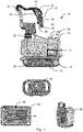
- the construction site box 10 is for providing tools, Machine tools, machine tool parts and consumables set up on a construction site, for example on a structural or civil engineering site.
- the construction site box 10 comprises a housing 12 on which a mobile locomotion platform 14 is arranged on the underside.
- a manipulator 16 is located on top of the housing 12.
- the mobile locomotion platform 14 is designed as a chain drive. These are two chains, one of which is shown in the side view 1 only a chain 18 can be seen, can be driven by a motor 20 to drive the locomotion platform 14 .
- the motor 20 can be supplied with electrical energy by an energy store 21 designed as a lithium-based accumulator.
- the energy store 21 is arranged inside the housing 12 and therefore in 1 shown only schematically.
- the manipulator 16 is arranged on the housing 12 via a lifting device 22 .
- the lifting device 22 is set up to set a vertical position of the manipulator 16 and thereby increase the maximum range of the manipulator 16 .
- An end effector 24 is formed at the free end of the manipulator 16 .
- Dust, drilling dust or the like can be sucked out of the working area of the machine tool 26 via a suction line 28 in connection with a suction adapter 30 .
- a marking unit is also arranged on the end effector 24, in particular in the form of a spray nozzle 29, with which paint can be sprayed, for example to create colored markings.
- An optical recording device 34 is arranged to the side of the machine tool 26 .
- the optical recording device 34 has a time-of-flight camera so that a three-dimensional image of the working area of the machine tool 26 and its surroundings can be recorded.
- a position marker 36 is also arranged in the area of the end effector 24 .
- the position mark 36 is designed in the form of a polyhedral mirror surface in order to interact with a position and position detection unit, which is described in more detail below.
- a charge status display unit 38 for displaying the available remaining energy of the energy store 21 is also arranged on the upper side of the housing 12 .
- an emergency stop switch 40 is provided, with which the construction site box 10 and any connected devices can be switched off at short notice if necessary.
- a docking station 39 is also arranged on the housing 12 and is designed to accommodate a tablet computer 42 .
- the tablet computer 42 is in 1 shown as one of several individual parts in a separate front view. In particular, it has a computer unit with which a display unit 44 can be controlled. Furthermore, the tablet computer 42 is equipped, among other things, with a microphone 46 for recording voice signals or the like.
- a radio remote control 48 can also be seen, with which the locomotion platform 14 can be remotely controlled. It offers the possibility of to control the chains 18 independently of one another, so that the locomotion platform 14 designed as a chain undercarriage can be controlled forwards, backwards, to the left, to the right or, in particular by controlling the chains 18 in the opposite direction, rotating on the spot.
- FIG. 1 10 shows a position and location detection unit 50 in the form of an automatic total station as a further individual part of the construction site box 10 in a perspective view obliquely from the front.
- the position and location detection unit 50 is set up to interact with the position marker 36 in order to determine both the position of the construction site box 10 and its position or alignment relative to a predefined coordinate system, for example by markers distributed throughout the construction site. Since the position mark 36 is arranged in the area of the end effector 24, it is possible to determine both the position and the alignment or position of the end effector 24 and thus of the machine tool 26 accommodated therein.
- FIG. 2 shows a charging station 52 of the construction site box 10 ( 1 ).
- the charging station 52 is formed in a rear area of the construction site box 10 .
- the charging station 52 is located within the housing 12.
- the housing 12 In order to be able to access the charging station 52, the housing 12 has a hinged, in 2 invisible housing cover.
- the charging station 52 has a charging device 54 with which external energy stores, in particular accumulators 56, can be charged.
- the accumulators 56 of which only one is provided with a reference symbol, represent replacement accumulators. They are therefore stored in accumulator receptacles 57, one of which in turn is provided with a reference symbol, until they are used later.
- further receptacles are formed in the area of the charging station 52, for example a line laser receptacle 58 and a distance meter receptacle 60 , in each of which a line laser and a distance meter are accommodated.
- the tablet computer 42, the radio remote control 48 and the position and location detection unit 50 can be stored in corresponding receptacles in the charging station 52.
- FIG 3 shows a side compartment 62 of the construction site box 10 ( 1 ).
- a measuring utensil holder 64 can be seen, in which the measuring utensil belonging to the position and location detection unit 50, for example a dipstick for the separate determination of positions on a construction site, are accommodated.
- a suction device 68 is also accommodated in a suction device receptacle 64 .
- the suction device 68 can be removed from the construction site box 10 so that it can also be used independently of the construction site box 10 . It is connected to the suction line 28 ( 1 ) connectable.
- a compressor 70 designed as a compressed air compressor can also be seen, which, in conjunction with a paint container 72 , controls the spray nozzle 29 ( 1 ) supplied with color.
- a consumables holder 74 is provided, in which various service and/or consumables, for example paint and/or thinner, can be stored.
- FIG 4 shows a control room 76 of the construction site box 10 ( 1 ), located inside the housing 12 behind an in 4 opened and only partially visible housing cover 77 is located.
- the control room 76 has a computer unit 78 designed in the form of a standing computer.
- the computer unit 78 is connected to a communication interface 80 .
- the communication interface 80 has a mobile radio receiver and a WLAN interface.
- the communication interface 80 is set up in particular to be operated as a router. For this purpose, it is set up to transfer data between the mobile radio interface and the WLAN interface. It is also set up, network connections to the tablet computer 42 ( 1 ) and, if necessary, to other devices, such as another construction site box.
- FIG. 5 a side compartment 82 of the construction site box 10, which is also inside the housing 12 and behind an in figure 5 invisible, hinged housing cover is located.
- a machine tool holder 84 and a tool holder 86 are formed in the side compartment 82 .
- a receptacle for consumables such as screw anchors or the like is formed, the consumables preferably being able to be removed for further processing with the end effector 24 or a consumables gripping device located thereon.
Landscapes
- Engineering & Computer Science (AREA)
- Mechanical Engineering (AREA)
- Robotics (AREA)
- Multimedia (AREA)
- Human Computer Interaction (AREA)
- Manipulator (AREA)
- Conveying And Assembling Of Building Elements In Situ (AREA)
- Workshop Equipment, Work Benches, Supports, Or Storage Means (AREA)
Priority Applications (6)
| Application Number | Priority Date | Filing Date | Title |
|---|---|---|---|
| EP20200968.4A EP3981551A1 (fr) | 2020-10-09 | 2020-10-09 | Conteneur de chantier |
| JP2023519197A JP2023544697A (ja) | 2020-10-09 | 2021-10-05 | 建設現場用箱体 |
| US18/028,926 US20230330832A1 (en) | 2020-10-09 | 2021-10-05 | Construction-site box |
| PCT/EP2021/077421 WO2022073991A1 (fr) | 2020-10-09 | 2021-10-05 | Coffre de chantier |
| KR1020237011852A KR20230082618A (ko) | 2020-10-09 | 2021-10-05 | 건설 현장 박스 |
| CN202180051754.8A CN115916470A (zh) | 2020-10-09 | 2021-10-05 | 建筑工地箱 |
Applications Claiming Priority (1)
| Application Number | Priority Date | Filing Date | Title |
|---|---|---|---|
| EP20200968.4A EP3981551A1 (fr) | 2020-10-09 | 2020-10-09 | Conteneur de chantier |
Publications (1)
| Publication Number | Publication Date |
|---|---|
| EP3981551A1 true EP3981551A1 (fr) | 2022-04-13 |
Family
ID=73043002
Family Applications (1)
| Application Number | Title | Priority Date | Filing Date |
|---|---|---|---|
| EP20200968.4A Pending EP3981551A1 (fr) | 2020-10-09 | 2020-10-09 | Conteneur de chantier |
Country Status (6)
| Country | Link |
|---|---|
| US (1) | US20230330832A1 (fr) |
| EP (1) | EP3981551A1 (fr) |
| JP (1) | JP2023544697A (fr) |
| KR (1) | KR20230082618A (fr) |
| CN (1) | CN115916470A (fr) |
| WO (1) | WO2022073991A1 (fr) |
Citations (5)
| Publication number | Priority date | Publication date | Assignee | Title |
|---|---|---|---|---|
| EP3189943A1 (fr) * | 2016-01-07 | 2017-07-12 | Festool GmbH | Dispositif de transfert et récipient empilable en étant équipé |
| US20180326507A1 (en) * | 2014-10-28 | 2018-11-15 | Nlink As | Mobile robotic drilling apparatus and method for drilling ceilings and walls |
| DE202017105337U1 (de) * | 2017-09-05 | 2018-12-07 | Kuka Deutschland Gmbh | Omnidirektionales, autonomes Fahrzeug mit einer Bohrvorrichtung |
| US20190154792A1 (en) | 2016-08-03 | 2019-05-23 | Black & Decker Inc. | Construction jobsite computer data network and location system |
| DE102018109744A1 (de) * | 2018-04-23 | 2019-10-24 | E. Zoller Gmbh & Co. Kg | Werkzeugtransportwagen, Werkzeugtransportsystem und Verfahren mit einem Werkzeugtransportwagen |
-
2020
- 2020-10-09 EP EP20200968.4A patent/EP3981551A1/fr active Pending
-
2021
- 2021-10-05 JP JP2023519197A patent/JP2023544697A/ja active Pending
- 2021-10-05 KR KR1020237011852A patent/KR20230082618A/ko unknown
- 2021-10-05 CN CN202180051754.8A patent/CN115916470A/zh active Pending
- 2021-10-05 US US18/028,926 patent/US20230330832A1/en active Pending
- 2021-10-05 WO PCT/EP2021/077421 patent/WO2022073991A1/fr active Application Filing
Patent Citations (5)
| Publication number | Priority date | Publication date | Assignee | Title |
|---|---|---|---|---|
| US20180326507A1 (en) * | 2014-10-28 | 2018-11-15 | Nlink As | Mobile robotic drilling apparatus and method for drilling ceilings and walls |
| EP3189943A1 (fr) * | 2016-01-07 | 2017-07-12 | Festool GmbH | Dispositif de transfert et récipient empilable en étant équipé |
| US20190154792A1 (en) | 2016-08-03 | 2019-05-23 | Black & Decker Inc. | Construction jobsite computer data network and location system |
| DE202017105337U1 (de) * | 2017-09-05 | 2018-12-07 | Kuka Deutschland Gmbh | Omnidirektionales, autonomes Fahrzeug mit einer Bohrvorrichtung |
| DE102018109744A1 (de) * | 2018-04-23 | 2019-10-24 | E. Zoller Gmbh & Co. Kg | Werkzeugtransportwagen, Werkzeugtransportsystem und Verfahren mit einem Werkzeugtransportwagen |
Non-Patent Citations (1)
| Title |
|---|
| KIT LEHRE UND WISSEN: "Assistenz-Roboter ARMAR 6 @ CEBIT 2018", 10 July 2018 (2018-07-10), pages 1, XP054981632, Retrieved from the Internet <URL:https://www.youtube.com/watch?v=GqIh3BiSTjE> [retrieved on 20210330] * |
Also Published As
| Publication number | Publication date |
|---|---|
| CN115916470A (zh) | 2023-04-04 |
| US20230330832A1 (en) | 2023-10-19 |
| JP2023544697A (ja) | 2023-10-25 |
| WO2022073991A1 (fr) | 2022-04-14 |
| KR20230082618A (ko) | 2023-06-08 |
Similar Documents
| Publication | Publication Date | Title |
|---|---|---|
| EP3415070B1 (fr) | Système pourvu d'au moins deux dispositifs de traitement du sol | |
| DE102015206571B3 (de) | Roboter-Bedienhandgerät mit einer Adaptervorrichtung für ein mobiles Endgerät | |
| EP3379990B1 (fr) | Systeme de nettoyage de sol et procede de nettoyage d'une surface | |
| US20190291257A1 (en) | Overhead drill and anchor press | |
| EP3416018B1 (fr) | Système pourvu d'au moins deux appareils de traitement du sol | |
| DE102012003690A1 (de) | Mobiler Roboter | |
| EP2617529A2 (fr) | Procédé avec une machine-outil manuelle et un ordinateur portable | |
| EP2631042A2 (fr) | Agencement de robot et procédé de fonctionnement | |
| EP1926572A1 (fr) | Installation d'usinage | |
| DE102012003663A1 (de) | Mobiler Roboter, Bearbeitungsstation und Verfahren zum Betreiben eines mobilen Roboters | |
| US11890737B2 (en) | Overhead drill and anchor press | |
| DE102015226734A1 (de) | Industrielles Gerät und tragbare Vorrichtung | |
| EP3272261A2 (fr) | Dispositif portatif avec bloc d'accumulateurs | |
| DE102015100419A1 (de) | Verfahren und Anordnung zum Bearbeiten von Bodenflächen | |
| EP2878249A1 (fr) | Aspirateur multifonction | |
| EP3159114B1 (fr) | Dispositif d'accumulation d'energie portatif destine a alimenter des outils | |
| EP3446834A1 (fr) | Marteau électrique | |
| WO2016146194A1 (fr) | Coffre à outils pourvu d'une partie coffre inférieure et d'un couvercle | |
| DE202017105337U1 (de) | Omnidirektionales, autonomes Fahrzeug mit einer Bohrvorrichtung | |
| EP2960014A2 (fr) | Dispositif de ponçage ou de fraisage pour la rénovation de bâtiment | |
| EP3558601B1 (fr) | Pupitre de commande de robot | |
| EP3981551A1 (fr) | Conteneur de chantier | |
| DE102016225688A1 (de) | Mobile Plattform mit einem Steuerpult | |
| EP4114617A1 (fr) | Dispositif d'alimentation en énergie destiné à une machine-outil | |
| RU142363U1 (ru) | Мобильный робот |
Legal Events
| Date | Code | Title | Description |
|---|---|---|---|
| PUAI | Public reference made under article 153(3) epc to a published international application that has entered the european phase |
Free format text: ORIGINAL CODE: 0009012 |
|
| STAA | Information on the status of an ep patent application or granted ep patent |
Free format text: STATUS: THE APPLICATION HAS BEEN PUBLISHED |
|
| AK | Designated contracting states |
Kind code of ref document: A1 Designated state(s): AL AT BE BG CH CY CZ DE DK EE ES FI FR GB GR HR HU IE IS IT LI LT LU LV MC MK MT NL NO PL PT RO RS SE SI SK SM TR |
|
| STAA | Information on the status of an ep patent application or granted ep patent |
Free format text: STATUS: REQUEST FOR EXAMINATION WAS MADE |
|
| 17P | Request for examination filed |
Effective date: 20221013 |
|
| RBV | Designated contracting states (corrected) |
Designated state(s): AL AT BE BG CH CY CZ DE DK EE ES FI FR GB GR HR HU IE IS IT LI LT LU LV MC MK MT NL NO PL PT RO RS SE SI SK SM TR |