EP3981538A1 - Processing program creation device, method for determining scattering direction of molten metal, laser processing machine, and laser processing method - Google Patents
Processing program creation device, method for determining scattering direction of molten metal, laser processing machine, and laser processing method Download PDFInfo
- Publication number
- EP3981538A1 EP3981538A1 EP20818465.5A EP20818465A EP3981538A1 EP 3981538 A1 EP3981538 A1 EP 3981538A1 EP 20818465 A EP20818465 A EP 20818465A EP 3981538 A1 EP3981538 A1 EP 3981538A1
- Authority
- EP
- European Patent Office
- Prior art keywords
- angle
- processing
- opening
- sheet metal
- laser beam
- Prior art date
- Legal status (The legal status is an assumption and is not a legal conclusion. Google has not performed a legal analysis and makes no representation as to the accuracy of the status listed.)
- Granted
Links
Images










Classifications
-
- G—PHYSICS
- G05—CONTROLLING; REGULATING
- G05B—CONTROL OR REGULATING SYSTEMS IN GENERAL; FUNCTIONAL ELEMENTS OF SUCH SYSTEMS; MONITORING OR TESTING ARRANGEMENTS FOR SUCH SYSTEMS OR ELEMENTS
- G05B19/00—Program-control systems
- G05B19/02—Program-control systems electric
- G05B19/18—Numerical control [NC], i.e. automatically operating machines, in particular machine tools, e.g. in a manufacturing environment, so as to execute positioning, movement or co-ordinated operations by means of program data in numerical form
- G05B19/4093—Numerical control [NC], i.e. automatically operating machines, in particular machine tools, e.g. in a manufacturing environment, so as to execute positioning, movement or co-ordinated operations by means of program data in numerical form characterised by part programming, e.g. entry of geometrical information as taken from a technical drawing, combining this with machining and material information to obtain control information, named part program, for the NC machine
-
- B—PERFORMING OPERATIONS; TRANSPORTING
- B23—MACHINE TOOLS; METAL-WORKING NOT OTHERWISE PROVIDED FOR
- B23K—SOLDERING OR UNSOLDERING; WELDING; CLADDING OR PLATING BY SOLDERING OR WELDING; CUTTING BY APPLYING HEAT LOCALLY, e.g. FLAME CUTTING; WORKING BY LASER BEAM
- B23K26/00—Working by laser beam, e.g. welding, cutting or boring
- B23K26/36—Removing material
- B23K26/38—Removing material by boring or cutting
-
- B—PERFORMING OPERATIONS; TRANSPORTING
- B23—MACHINE TOOLS; METAL-WORKING NOT OTHERWISE PROVIDED FOR
- B23K—SOLDERING OR UNSOLDERING; WELDING; CLADDING OR PLATING BY SOLDERING OR WELDING; CUTTING BY APPLYING HEAT LOCALLY, e.g. FLAME CUTTING; WORKING BY LASER BEAM
- B23K26/00—Working by laser beam, e.g. welding, cutting or boring
- B23K26/02—Positioning or observing the workpiece, e.g. with respect to the point of impact; Aligning, aiming or focusing the laser beam
- B23K26/04—Automatically aligning, aiming or focusing the laser beam, e.g. using the back-scattered light
-
- B—PERFORMING OPERATIONS; TRANSPORTING
- B23—MACHINE TOOLS; METAL-WORKING NOT OTHERWISE PROVIDED FOR
- B23K—SOLDERING OR UNSOLDERING; WELDING; CLADDING OR PLATING BY SOLDERING OR WELDING; CUTTING BY APPLYING HEAT LOCALLY, e.g. FLAME CUTTING; WORKING BY LASER BEAM
- B23K26/00—Working by laser beam, e.g. welding, cutting or boring
- B23K26/08—Devices involving relative movement between laser beam and workpiece
- B23K26/0869—Devices involving movement of the laser head in at least one axial direction
-
- B—PERFORMING OPERATIONS; TRANSPORTING
- B23—MACHINE TOOLS; METAL-WORKING NOT OTHERWISE PROVIDED FOR
- B23K—SOLDERING OR UNSOLDERING; WELDING; CLADDING OR PLATING BY SOLDERING OR WELDING; CUTTING BY APPLYING HEAT LOCALLY, e.g. FLAME CUTTING; WORKING BY LASER BEAM
- B23K26/00—Working by laser beam, e.g. welding, cutting or boring
- B23K26/14—Working by laser beam, e.g. welding, cutting or boring using a fluid stream, e.g. a jet of gas, in conjunction with the laser beam; Nozzles therefor
- B23K26/142—Working by laser beam, e.g. welding, cutting or boring using a fluid stream, e.g. a jet of gas, in conjunction with the laser beam; Nozzles therefor for the removal of by-products
-
- B—PERFORMING OPERATIONS; TRANSPORTING
- B23—MACHINE TOOLS; METAL-WORKING NOT OTHERWISE PROVIDED FOR
- B23K—SOLDERING OR UNSOLDERING; WELDING; CLADDING OR PLATING BY SOLDERING OR WELDING; CUTTING BY APPLYING HEAT LOCALLY, e.g. FLAME CUTTING; WORKING BY LASER BEAM
- B23K26/00—Working by laser beam, e.g. welding, cutting or boring
- B23K26/14—Working by laser beam, e.g. welding, cutting or boring using a fluid stream, e.g. a jet of gas, in conjunction with the laser beam; Nozzles therefor
- B23K26/1462—Nozzles; Features related to nozzles
- B23K26/1464—Supply to, or discharge from, nozzles of media, e.g. gas, powder, wire
-
- G—PHYSICS
- G05—CONTROLLING; REGULATING
- G05B—CONTROL OR REGULATING SYSTEMS IN GENERAL; FUNCTIONAL ELEMENTS OF SUCH SYSTEMS; MONITORING OR TESTING ARRANGEMENTS FOR SUCH SYSTEMS OR ELEMENTS
- G05B19/00—Program-control systems
- G05B19/02—Program-control systems electric
- G05B19/18—Numerical control [NC], i.e. automatically operating machines, in particular machine tools, e.g. in a manufacturing environment, so as to execute positioning, movement or co-ordinated operations by means of program data in numerical form
- G05B19/182—Numerical control [NC], i.e. automatically operating machines, in particular machine tools, e.g. in a manufacturing environment, so as to execute positioning, movement or co-ordinated operations by means of program data in numerical form characterised by the machine tool function, e.g. thread cutting, cam making, tool direction control
-
- B—PERFORMING OPERATIONS; TRANSPORTING
- B23—MACHINE TOOLS; METAL-WORKING NOT OTHERWISE PROVIDED FOR
- B23K—SOLDERING OR UNSOLDERING; WELDING; CLADDING OR PLATING BY SOLDERING OR WELDING; CUTTING BY APPLYING HEAT LOCALLY, e.g. FLAME CUTTING; WORKING BY LASER BEAM
- B23K2101/00—Articles made by soldering, welding or cutting
- B23K2101/18—Sheet panels
-
- G—PHYSICS
- G05—CONTROLLING; REGULATING
- G05B—CONTROL OR REGULATING SYSTEMS IN GENERAL; FUNCTIONAL ELEMENTS OF SUCH SYSTEMS; MONITORING OR TESTING ARRANGEMENTS FOR SUCH SYSTEMS OR ELEMENTS
- G05B2219/00—Program-control systems
- G05B2219/30—Nc systems
- G05B2219/36—Nc in input of data, input key till input tape
- G05B2219/36199—Laser cutting
-
- G—PHYSICS
- G05—CONTROLLING; REGULATING
- G05B—CONTROL OR REGULATING SYSTEMS IN GENERAL; FUNCTIONAL ELEMENTS OF SUCH SYSTEMS; MONITORING OR TESTING ARRANGEMENTS FOR SUCH SYSTEMS OR ELEMENTS
- G05B2219/00—Program-control systems
- G05B2219/30—Nc systems
- G05B2219/45—Nc applications
- G05B2219/45234—Thin flat workpiece, sheet metal machining
-
- G—PHYSICS
- G05—CONTROLLING; REGULATING
- G05B—CONTROL OR REGULATING SYSTEMS IN GENERAL; FUNCTIONAL ELEMENTS OF SUCH SYSTEMS; MONITORING OR TESTING ARRANGEMENTS FOR SUCH SYSTEMS OR ELEMENTS
- G05B2219/00—Program-control systems
- G05B2219/30—Nc systems
- G05B2219/49—Nc machine tool, till multiple
- G05B2219/49331—Laser drilling followed by laser cutting
-
- Y—GENERAL TAGGING OF NEW TECHNOLOGICAL DEVELOPMENTS; GENERAL TAGGING OF CROSS-SECTIONAL TECHNOLOGIES SPANNING OVER SEVERAL SECTIONS OF THE IPC; TECHNICAL SUBJECTS COVERED BY FORMER USPC CROSS-REFERENCE ART COLLECTIONS [XRACs] AND DIGESTS
- Y02—TECHNOLOGIES OR APPLICATIONS FOR MITIGATION OR ADAPTATION AGAINST CLIMATE CHANGE
- Y02P—CLIMATE CHANGE MITIGATION TECHNOLOGIES IN THE PRODUCTION OR PROCESSING OF GOODS
- Y02P90/00—Enabling technologies with a potential contribution to greenhouse gas [GHG] emissions mitigation
- Y02P90/02—Total factory control, e.g. smart factories, flexible manufacturing systems [FMS] or integrated manufacturing systems [IMS]
Definitions
- the present disclosure relates to a processing program creation device, a method for determining a scattering direction of molten metal, a laser processing machine, and a laser processing method.
- a laser processing machine that cuts a sheet metal with a laser beam that is emitted from a laser oscillator is widely used.
- the laser processing machine opens a hole called a pierced hole in a sheet metal, at a position at an outer part of the product.
- the laser processing machine performs approach processing of cutting up to a predetermined position at an outer circumference of the product, and then cuts the sheet metal along the outer circumference of the product.
- Patent Literature 1 Japanese Patent No. 3761687
- the laser processing machine performs the piercing processing or cuts the sheet metal by irradiating the sheet metal with the laser beam while blowing assist gas according to the material of the sheet metal onto the sheet metal.
- molten metal generated by the laser beam is blown away by the assist gas to a rear surface side of the sheet metal through a groove that is already cut.
- the molten metal is blown away by the assist gas to an upper surface of the sheet metal to be adhered to a periphery of the pierced hole (see Patent Literature 1).
- the laser beam passes through the center of a circular opening of a nozzle, and the assist gas is blown onto the sheet metal through a periphery of the laser beam. If the sheet metal has a small thickness, the assist gas is applied to the molten metal approximately uniformly in a circumferential direction, and the molten metal is approximately uniformly scattered. However, if the sheet metal has a great thickness, formation of the pierced hole takes a long time, and a phenomenon is possibly caused in which a part being melted subtly moves in a planar direction.
- the amount of molten metal becomes non-uniform in the circumferential direction by being largely distributed in a predetermined direction, and a greater amount of molten metal is scattered in the direction in which the amount is largely distributed.
- the direction in which the amount of molten metal is largely distributed is random, and thus, the direction in which a greater amount of molten metal is scattered is random.
- the pierced hole has to be formed at a position that is sufficiently away from the product.
- a sufficient space for forming the pierced hole has to be provided between adjacent products. Accordingly, the maximum number of products that can be cut out cannot be increased, and the yield cannot be increased.
- metal deposits (spatters) that are molten metal that is adhered and solidified around the pierced hole possibly reduce stability of the approach processing and may cause processing defects.
- yield may be increased and occurrence of processing defects may be made less likely. If the laser processing machine is capable of performing the piercing processing while causing the molten metal to be scattered in the most desirable direction, the yield may be increased and occurrence of processing defects may be made less likely.
- One or more embodiments are directed to providing a processing program creation device that is capable of creating a processing program for enabling control of a direction in which molten metal is to be scattered at a time of piercing processing, a method for determining a scattering direction of the molten metal, the method being capable of automatically determining a most desirable direction in which the molten metal is to be scattered at the time of the piercing processing, and a laser processing machine and a laser processing method that are capable of performing the piercing processing while causing the molten metal to be scattered in the most desirable direction.
- a processing program creation device including: an optimum scattering angle calculator configured to calculate an optimum scattering angle that is an angle most desirable for scattering of molten metal in a search region at a time of piercing processing of opening a pierced hole in a sheet metal to cut the sheet metal and fabricate a first product, the molten metal being generated by melting of the sheet metal, the search region being a circle having a predetermined radius and centered on a center of the pierced hole, the molten metal being not adhered to an approach path extending to the pierced hole and not adhered to a processing path for a second product positioned within the search region at the optimum scattering angle; and a program creator configured to create a processing program by adding an auxiliary code to a code for cutting the sheet metal and fabricating the first product, the auxiliary code indicating that, at a time of the piercing processing on the first product, a position of a laser beam
- a method for determining a scattering direction of molten metal including, by a computer appliance: setting a search region that is a circle having a predetermined radius and centered on a center of a pierced hole to be opened to cut a sheet metal and fabricate a first product; setting a scattering angle region having a center angle based on a spread angle of spatters determined in advance, the scattering angle region being where molten metal generated by melting of the sheet metal is scattered and spread in a fan shape to be adhered to the sheet metal when a position of a laser beam in an opening of a nozzle attached to a tip end of a processing head is displaced from a center of the opening while assist gas is being blown onto the sheet metal from the opening, the laser beam being emitted from the opening; extracting, from the search region, one or more angle regions at least having an angle range of the scattering angle region, the angle region not interfering with either an approach
- a laser processing machine including: a processing head including a nozzle attached to a tip end, the nozzle being for emitting a laser beam from an opening; a moving mechanism configured to move the processing head along a surface of a sheet metal; a beam displacement mechanism configured to displace a position, in the opening, of the laser beam emitted from the opening; an assist gas supply device configured to supply, to the processing head, assist gas to be blown onto the sheet metal from the opening at a time of processing of the sheet metal; and a control device configured to control the beam displacement mechanism at a time of piercing processing of opening a pierced hole in the sheet metal to cut a product based on a processing program, the beam displacement mechanism being controlled such that, in a case where an auxiliary code indicating an angle direction in which the position, in the opening, of the laser beam emitted from the opening is to be displaced from a center of the opening is written in the processing program, the laser beam is
- a laser processing method including, by a control device configured to control a laser processing machine: reading an auxiliary code at a time of controlling the laser processing machine based on a processing program such that piercing processing of opening a pierced hole to cut a product is performed on a sheet metal, in a case where the auxiliary code is written in the processing program, the auxiliary code indicating an angle direction in which a laser beam emitted from an opening of a nozzle attached to a tip end of a processing head is to be displaced from a center of the opening; controlling a beam displacement mechanism provided in the laser processing machine in such a manner that the laser beam with which the sheet metal is irradiated at a time of the piercing processing is displaced in the angle direction indicated by the auxiliary code; and controlling an assist gas supply device provided in the laser processing machine in such a manner that assist gas is blown onto the sheet metal from the opening at the time of the piercing processing.
- a processing program that is capable of controlling the direction of scattering of molten metal at the time of piercing processing may be created.
- a direction in which the molten metal is most desirably scattered at the time of the piercing processing may be automatically determined.
- the piercing processing may be performed by causing the molten metal to be scattered in the most desirable direction.
- a laser processing machine 100 includes a laser oscillator 10 for generating and emitting a laser beam, a laser processing unit 20, and a process fiber 12 for transmitting the laser beam emitted from the laser oscillator 10 to the laser processing unit 20.
- the laser processing machine 100 further includes an operation section 1, a computer appliance 2 that executes a computer aided manufacturing (CAM) program, an operation section 40, an NC device 50, a processing program database 60, a processing condition database 70, and an assist gas supply device 80.
- CAM computer aided manufacturing
- the operation section 1, the computer appliance 2, the processing program database 60, and the processing condition database 70 may be provided outside the laser processing machine 100.
- the processing program database 60 and the processing condition database 70 may be connected to the NC device 50 via a network.
- the computer appliance 2 is a processing program creation device that creates a processing program.
- the NC device 50 is an example of a control device for controlling each part of the laser processing machine 100.
- the laser oscillator 10 a laser oscillator that emits a laser beam at a predetermined wavelength by amplifying an excitation beam emitted from a laser diode, or a laser oscillator that directly uses a laser beam that is emitted from a laser diode is suitably used.
- the laser oscillator 10 is a solid laser oscillator, a fiber laser oscillator, a disk laser oscillator, or a direct diode laser oscillator (a DDL oscillator).
- the laser oscillator 10 emits a 1- ⁇ m band laser beam at a wavelength of 900 nm to 1100 nm.
- the fiber laser oscillator emits a laser beam at a wavelength of 1060 nm to 1080 nm
- the DDL oscillator emits a laser beam at a wavelength of 910 nm to 950 nm.
- the laser processing unit 20 includes a processing table 21 on which to place a sheet metal W as a processing target, a gate-type X-axis carriage 22, a Y-axis carriage 23, a collimator unit 30 fixed to the Y-axis carriage 23, and a processing head 35.
- the X-axis carriage 22 is freely movable on the processing table 21 in an X-axis direction.
- the Y-axis carriage 23 is freely movable on the X-axis carriage 22 in a Y-axis direction perpendicular to an X-axis.
- the X-axis carriage 22 and the Y-axis carriage 23 function as a moving mechanism for moving the processing head 35 along a surface of the sheet metal W, in the X-axis direction, the Y-axis direction, or any combination direction along the X-axis and the Y-axis.
- the sheet metal W may be moved while fixing a position of the processing head 35. It suffices if the laser processing machine 100 includes a moving mechanism for moving the processing head 35 relative to the surface of the sheet metal W.
- a nozzle 36 including a circular opening 36a at a tip end portion is attached to the processing head 35, the nozzle 36 being for emitting a laser beam from the opening 36a.
- the sheet metal W is irradiated with a laser beam that is emitted from the opening 36a of the nozzle 36.
- the collimator unit 30 includes a collimation lens 31 for converting a laser beam that is a divergent beam emitted from the process fiber 12 into a parallel beam (a collimated beam).
- the collimator unit 30 also includes a galvano scanner unit 32, and a bend mirror 33 for reflecting a laser beam emitted from the galvano scanner unit 32 downward in a Z-axis direction perpendicular to the X-axis and the Y-axis.
- the processing head 35 includes a focusing lens 34 for focusing a laser beam reflected by the bend mirror 33, and for irradiating the sheet metal W with the focused laser beam.
- the laser processing machine 100 is aligned such that the laser beam that is emitted from the opening 36a of the nozzle 36 is positioned at a center of the opening 36a. In a standard state, the laser beam is emitted from the center of the opening 36a.
- the galvano scanner unit 32 functions as a beam displacement mechanism for displacing the position, inside the opening 36a, of the laser beam that proceeds through the processing head 35 to be emitted from the opening 36a. As a result, the galvano scanner unit 32 displaces the position, on the sheet metal W, that is to be irradiated with the laser beam to a position that is away from a position immediately below the center of the opening 36a by a predetermined distance.
- the galvano scanner unit 32 is an example of the beam displacement mechanism, and the beam displacement mechanism is not limited to the galvano scanner unit 32.
- the galvano scanner unit 32 includes a scanning mirror 321 for reflecting the laser beam emitted through the collimation lens 31, and a driver 322 for rotating the scanning mirror 321 to a predetermined angle.
- the galvano scanner unit 32 also includes a scanning mirror 323 for reflecting the laser beam emitted from the scanning mirror 321, and a driver 324 for rotating the scanning mirror 323 to a predetermined angle.
- the laser processing machine 100 configured in the above manner fabricates a product having a predetermined shape by cutting the sheet metal W with a laser beam emitted from the laser oscillator 10. At this time, the laser processing machine 100 performs piercing processing on a position, on the sheet metal W, outside the product with a laser beam, and cuts a linear approach path from a pierced hole to a predetermined position on an outer circumference of the product. The laser processing machine 100 fabricates the product by cutting the sheet metal along the outer circumference of the product when the laser beam reaches the predetermined position on the outer circumference of the product that is an end of the approach path on the product side.
- the laser processing machine 100 may reduce the amount of molten metal adhered to the product side, by controlling the direction around the pierced hole in which the molten metal is to be attached. The laser processing machine 100 may also prevent molten metal from getting adhered on the product side around the pierced hole.
- Figures 3A and 3B conceptually show a piercing processing operation performed on the sheet metal W using a typical laser processing method. That is, there is shown a piercing processing operation according to which the center of the opening 36a is positioned immediately above a position where the piercing processing is to be performed, where the sheet metal W is irradiated with the laser beam at immediately below the center of the opening 36a.
- Figure 3A shows a case where the sheet metal W has a small thickness
- Figure 3B shows a case where the sheet metal W has a great thickness.
- the NC device 50 raises the processing head 35 to separate the nozzle 36 from the sheet metal W. Accordingly, a beam waist of the laser beam indicated by a dash-dotted line is positioned above and away from the sheet metal W. Additionally, depending on how a lens is adjusted, the beam waist may be set on the surface of or inside the sheet metal W, and a position of the beam waist may be freely selected.
- the sheet metal W is irradiated with the laser beam having passed through the center of the opening 36a, and metal at an irradiation position is melted into molten metal Wmelt by heat from the laser beam.
- Assist gas AG supplied to the processing head 35 by the assist gas supply device 80 passes through the opening 36a to be blown onto the sheet metal W.
- the assist gas AG is applied to the molten metal Wmelt approximately uniformly in a circumferential direction, and the molten metal Wmelt is approximately uniformly scattered around a position to be the pierced hole.
- the molten metal Wmelt that is scattered and a metal deposit adhered and solidified on the sheet metal W may both be referred to as a spatter, but in the one or more embodiments, the metal deposit is referred to as the spatter.
- Figure 3B shows a state where a greater amount of molten metal Wmelt is scattered in a left direction in the drawing, and more spatters Sp are adhered in the left direction from the position where the pierced hole is to be formed.
- the direction in which the amount of molten metal Wmelt is to be largely distributed is random, and thus, the direction in which many spatters Sp are to be adhered due to scattering of a great amount of molten metal Wmelt is random.
- a case will be considered, as shown in Figure 4 , where a blank layout of a plurality of rectangular products 200 is created on the sheet metal W, and where each product 200 is to be cut by the laser processing machine 100.
- the computer appliance 2 creates a processing program for performing the piercing processing and opening a pierced hole 201 at a position shown in Figure 4 , cutting an approach path 202 after opening the pierced hole 201, and cutting the sheet metal W along an outer circumference of the product 200 after cutting the approach path 202 up to an edge portion of the product 200.
- the processing program is stored in the processing program database 60.
- the NC device 50 reads out the processing program from the processing program database 60, and performs selection from a plurality of processing conditions stored in the processing condition database 70.
- the NC device 50 controls the laser processing machine 100 such that the sheet metal W is processed based on the processing program that is read out and the processing condition that is selected.
- the position where the piercing processing is to be performed to open the pierced hole 201 is set by the processing program to coordinates (X1, Y1) on the sheet metal W.
- the NC device 50 may position the processing head 35 such that the center of the opening 36a is positioned at the coordinates (X1, Y1).
- the center of the opening 36a is positioned immediately above the position where the pierced hole 201 is to be opened.
- the NC device 50 positions the processing head 35 such that the center of the opening 36a is positioned at the coordinates (X1, Y1).
- the NC device 50 changes the angle of the scanning mirror 321 or 323 of the galvano scanner unit 32 such that the position, on the sheet metal W, that is to be irradiated with the laser beam is positioned on an extended line of the approach path 202 and on a side away from the product 200 than the coordinates (X1, Y1).
- the position, on the sheet metal W, that is to be irradiated with the laser beam is displaced to a side away from the product 200 instead of being immediately below the center of the opening 36a.
- the NC device 50 may control the processing head 35 and the galvano scanner unit 32 in the manner shown in Figure 5C .
- the NC device 50 causes the processing head 35 to be displaced along the approach path 202 to be on the product 200 side such that the center of the opening 36a is positioned immediately above a position, on the approach path 202, displaced from the coordinates (X1, Y1) toward the product 200.
- the NC device 50 changes the angle of the scanning mirror 321 or 323 of the galvano scanner unit 32 such that the position, on the sheet metal W, that is to be irradiated with the laser beam comes at the coordinates (X1, Y1).
- the position, on the sheet metal W, that is to be irradiated with the laser beam is displaced not to immediately below the center of the opening 36a, but to a side away from the product 200.
- a fine solid line that is bent by the bend mirror 33 and that passes through the focusing lens 34 indicates an optical axis of the laser beam in a standard state of the laser processing machine 100. It is assumed that, due to the action of the galvano scanner unit 32, the optical axis of the laser beam is displaced from the position indicated by the fine solid line to a position indicated by a thick solid line.
- the laser beam reflected by the bend mirror 33 is inclined at an angle ⁇ , the irradiation position of the laser beam on the sheet metal W is displaced by a distance ⁇ s.
- an angle of the optical axis of the laser beam entering the bend mirror 33 is changed, and the optical axis is shifted from a center of the bend mirror 33.
- an incident position of the laser beam on the bend mirror 33 is shown to be at a same position before and after the action of the galvano scanner unit 32.
- the distance ⁇ s is calculated by EFL ⁇ sin ⁇ .
- the NC device 50 may simply tilt the optical axis of the laser beam by the angle ⁇ by the galvano scanner unit 32 such that the laser beam is displaced by the distance ⁇ s that is set in advance.
- the distance ⁇ s is a distance that is smaller than a radius of the opening 36a, and is preferably a distance that is equal to or smaller than a maximum distance, where the maximum distance is a distance obtained by subtracting a predetermined margin from the radius of the opening 36a.
- the focal length EFL of the focusing lens 34 is much greater than the distance ⁇ s and is 120 mm, 190 mm or the like, for example, whereas the distance ⁇ s is a distance of several tens to hundreds of micrometers. Accordingly, there is practically no problem in calculating the distance ⁇ s using the EFL without using an optical path length from the bend mirror 33 and without taking into account a refractive index of the focusing lens 34.
- the position of the beam waist that is set in a state where the irradiation position of the laser beam is not displaced is shifted in a thickness direction of the sheet metal W.
- the distance ⁇ s is a distance of several tens to hundreds of micrometers, and thus, a shift in the position of the beam waist is not likely to cause a problem.
- the focusing lens 34 may simply be displaced in the Z-axis direction, for example.
- FIG 7 (a) conceptually shows an operation of opening a pierced hole in the sheet metal W by a laser beam that is displaced from the center of the opening 36a to an outer side when seen from a lateral direction of the processing head 35, and (b) conceptually shows a state where the sheet metal W is seen from above the sheet metal W.
- the assist gas AG is blown onto the sheet metal W uniformly in the circumferential direction, but the laser beam with which the sheet metal W is irradiated is displaced, and thus, the molten metal Wmelt is scattered in the direction in which the laser beam is displaced.
- control may be performed in such a way that the spatters Sp are adhered to the sheet metal W at around the pierced hole 201, on an opposite side from the product 200, and that the spatters Sp are hardly adhered on the product 200 side. Accordingly, the pierced hole 201 may be opened near the product 200, and thus, a gap D between adjacent products 200 as shown in Figure 4 may be reduced. As a result, the one or more embodiments may increase the yield.
- the spatters Sp are hardly adhered to the approach path 202, and thus, the approach processing may be stably performed, and possibility of occurrence of processing defects may be reduced.
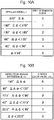
- a correspondence between the spread angle ⁇ and a spread determination degree is defined as shown in Figure 10A .
- the spread angles ⁇ of 270 degrees or more, 180 degrees or more and less than 270 degrees, 135 degrees or more and less than 180 degrees, 90 degrees or more and less than 135 degrees, 45 degrees or more and less than 90 degrees, and less than 45 degrees correspond to the spread determination degrees 0, 1, 2, 3, 4, and 5, respectively. The greater the spread determination degree, the better.
- a correspondence between the direction angle difference ⁇ and a direction determination degree is defined as shown in Figure 10B .
- the direction angle differences ⁇ of 135 degrees or more, 90 degrees or more and less than 135 degrees, 77.5 degrees or more and less than 90 degrees, 45 degrees or more and less than 77.5 degrees, 22.5 degrees or more and less than 45 degrees, and less than 22.5 degrees correspond to the direction determination degrees 0, 1, 2, 3, 4, and 5, respectively. The greater the direction determination degree, the better.
- a distance by which the position, on the sheet metal W, that is to be irradiated with the laser beam is displaced from the position immediately below the center of the opening 36a is given as an amount of displacement.
- the distance ⁇ s described in Figure 6 is the amount of displacement.
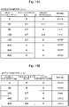
- the spread determination degree and the direction determination degree in Figures 11A and 11B each indicate an average value where the piercing processing is performed three times.
- Figure 11A shows a relationship among the amount of displacement, the spread determination degree, the direction determination degree, and a rating, where the piercing processing is performed on the sheet metal W that is stainless steel having a thickness of 6 mm, by using the nozzle 36 with a nozzle diameter of 2 mm and with a laser power of 4 kW.
- the amount of displacement is preferably 50 ⁇ m or more, and is, more preferably, 150 ⁇ m or more.
- Figure 11B shows the relationship among the amount of displacement, the spread determination degree, the direction determination degree, and the rating, where the piercing processing is performed on the sheet metal W under the same condition as in Figure 11A , but with the nozzle 36 with a nozzle diameter of 3 mm.
- the amount of displacement is preferably 250 ⁇ m or more, and is, more preferably, 450 ⁇ m or more.
- the NC device 50 may displace the position, on the sheet metal W, that is to be irradiated with the laser beam from the position immediately below the center of the opening 36a, by the amount of displacement that is optimally set according to conditions including the nozzle diameter, a shape of the nozzle 36, a nozzle gap at the time of the piercing processing, a gas pressure of the assist gas and the like.
- the laser beam with which the sheet metal W is irradiated is displaced along the approach path 202, in a direction away from the product 200.
- the laser beam is possibly more desirably displaced in a direction different from the direction along the approach path 202.
- an optimum scattering angle indicating a most desirable direction in which the molten metal is to be scattered is desirably automatically determined at the time of the piercing processing, and the laser beam is desirably displaced in the direction of the optimum scattering angle that is determined.
- the computer appliance 2 that is the processing program creation device creates a processing program for enabling automatic determination of the optimum scattering angle and displacement of the laser beam in the direction of the determined optimum scattering angle.
- a specific configuration of the computer appliance 2 will be described with reference to Figure 12 , and layout of a processing path for a product (a part) and blank layout of parts on the sheet metal W (a sheet) will be described with reference to Figures 13 and 14 .
- the computer appliance 2 includes an automatic layout section 211, an automatic blank layout section 212, an optimum scattering angle calculator 213, and a program creator 214.
- the automatic layout section 211 to the program creator 214 may be configured by a CAM program.
- Part data that is CAD data created by a computer appliance, not shown, that executes a computer aided design (CAD) program is input to the automatic layout section 211.
- the part data is shape data of one product such as the product 200.
- the computer appliance 2 may be the computer appliance that executes the CAD program. That is, the computer appliance 2 may be a CAD/CAM appliance that executes the CAD and CAM programs.
- the automatic layout section 211 creates layout data by laying out a processing path for cutting the approach path 202 subsequent to the piercing processing of opening the pierced hole 201 and then cutting the sheet metal W along an outer circumference 200L of the product 200.
- Sheet data indicating the sheet metal W, and instruction data indicating the number of products 200 to be cut from the sheet metal W are input to the automatic blank layout section 212.
- the number of products 200 to be cut is instructed by the operation section 1.
- the automatic blank layout section 212 creates blank layout data for cutting out nine products 200 from the sheet metal W, as shown in Figure 14 , based on the layout data for the sheet metal W shown in Figure 13 .
- the optimum scattering angle calculator 213 calculates the optimum scattering angle of molten metal for when opening each pierced hole 201, based on the blank layout data created by the automatic blank layout section 212.
- the program creator 214 creates a processing program by including an auxiliary code indicating the optimum scattering angle calculated by the optimum scattering angle calculator 213.
- the processing program is transmitted to and stored in the processing program database 60.
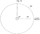
- the optimum scattering angle calculator 213 sets a search region 300 that is a circle having a predetermined radius r and centered on the center of the pierced hole 201.
- the radius r is 10 mm, for example.
- the optimum scattering angle calculator 213 defines an angle in a circumferential direction of the search region 300, where the position of the approach path is at 0 degrees. In the example shown in Figure 15 , 0 to 360 degrees are set in a counterclockwise direction, where the approach path 202 is seen from the pierced hole 201.
- the optimum scattering angle calculator 213 sets an angle region 301 between 90 degrees and 270 degrees in the search region 300, for example, as an angle region to be a candidate of a scattering angle in which molten metal is to be scattered.
- the angle region 301 will be referred to as a candidate angle region 301.
- the candidate angle region 301 is desirably the angle region between 90 degrees and 270 degrees.
- an operator may operate the operation section 1 to set the angles of the candidate angle region 301 to other than between 90 degrees and 270 degrees.
- the candidate angle region 301 has to be an angle region that does not include the approach path 202.
- the spread angle ⁇ in which the spatters Sp are to be spread in a fan shape may be set to a predetermined angle.
- the spread angle ⁇ may be made smaller than 45 degrees. Specifically what angle is to be adopted as the spread angle ⁇ can be determined in advance by an experiment.
- an angle region having the spread angle ⁇ is taken as a scattering angle region 302 where molten metal is to be scattered.
- a length 302w of a chord connecting both ends of a circular arc of the scattering angle region 302 is taken as a width of the scattering angle region 302.
- a center angle of the scattering angle region 302 is the spread angle ⁇ , but an angle that is wider than the spread angle ⁇ may alternatively be made the center angle of the scattering angle region 302 by taking the direction angle difference ⁇ into account. It suffices if the center angle of the scattering angle region 302 is set based on the spread angle ⁇ .
- the scattering angle region 302 has to be set to have an angle that does not include the processing path for the other product.
- the spread angle ⁇ that is set in advance or the spread angle ⁇ that is input by the operator through the operation section 1 is input to the optimum scattering angle calculator 213. Additionally, the length 302w of the chord may be input instead of the spread angle ⁇ .
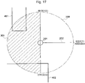
- processing paths 401 and 402 for another product are included in the candidate angle region 301.
- the other product is a second product.
- the processing paths 401 and 402 may be processing paths for one second product or may be processing paths for different second products.
- the processing paths 401 and 402 are not included in the search region 300 (the candidate angle region 301).
- the candidate angle region 301 To describe the manner of calculation of the optimum scattering angle in a case where there is a processing path for another product in the candidate angle region 301, a case is given as an example where the processing paths 401 and 402 for another product are included in the candidate angle region 301.
- the number of processing paths for another product included in the candidate angle region 301 is one or more.
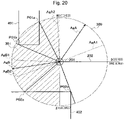
- the optimum scattering angle calculator 213 rotates the fan-shaped scattering angle region 302 (see Figure 16 ) around the center of the pierced hole 201, and extracts an angle region that does not interfere with any of the approach path 202 and the processing paths 401 and 402.
- the optimum scattering angle calculator 213 extracts, from the search region 300, fan-shaped angle regions ArA, ArB and ArC.
- the angle regions ArA, ArB and ArC are each an angle region at least having an angle range of the scattering angle region 302. In this case, three angle regions are extracted, but one or more angle regions may be extracted.
- the angle region ArA is an angle region from an angle greater than 0 degrees at which the scattering angle region 302 does not contact the approach path 202 to an angle just short of contact with a point P01a on the processing path 401.
- the angle region ArB is an angle region from an angle at which the scattering angle region 302 does not contact a point P01b on the processing path 401 to an angle just short of contact with a point P02a on the processing path 402.
- the angle region ArC is an angle region from an angle at which the scattering angle region 302 does not contact a point P02b on the processing path 402 to an angle less than 360 degrees at which the scattering angle region 302 does not contact the approach path 202.
- the optimum scattering angle calculator 213 arranges the scattering angle region 302 at both end portions, in an angle direction, within the angle regions ArA, ArB and ArC.
- the optimum scattering angle calculator 213 determines angles AgA1 and AgA2 where bisectors of two scattering angle regions 302 arranged in the angle region ArA are located.
- the optimum scattering angle calculator 213 determines angles AgB1 and AgB2 where bisectors of two scattering angle regions 302 arranged in the angle region ArB are located.
- the optimum scattering angle calculator 213 determines angles AgC1 and AgC2 where bisectors of two scattering angle regions 302 arranged in the angle region ArC are located.
- the optimum scattering angle calculator 213 determines an angle AgA where a bisector of a fan-shaped region between the angles AgA1 and AgA2 is located, and determines an angle AgB where a bisector of a fan-shaped region between the angles AgB1 and AgB2 is located. Neither of the angles AgC1 and AgC2 shown in Figure 19 is included in the candidate angle region 301, and thus, the optimum scattering angle calculator 213 does not determine an angle where a bisector of a fan-shaped region between the angles AgC1 and AgC2 is located, and the angle region ArC is excluded from targets for which the angle where a bisector is located is to be determined.
- the angles AgA and AgB are angles where the bisectors of the fan-shaped angle regions ArA and ArB are located. In the following, the angles AgA and AgB will be referred to as bisecting angles AgA and AgB.
- the optimum scattering angle calculator 213 corrects the same to 90 degrees; when the bisecting angle AgA or AgB is between 90 degrees and 270 degrees and is within the candidate angle region 301, the optimum scattering angle calculator 213 does not perform correction; when the bisecting angle AgA or AgB is more than 270 degrees, the optimum scattering angle calculator 213 corrects the same to 270 degrees.
- AgA' is a corrected bisecting angle that is the bisecting angle AgA shown in Figure 20 after being corrected to 90 degrees. The bisecting angle AgB is not corrected.
- the optimum scattering angle calculator 213 determines, as the optimum scattering angle, from the corrected bisecting angle AgA' and the bisecting angle AgB, an angle closest to an extended line obtained by extending the approach path 202 in a direction away from the product 200 (that is, an angle closest to 180 degrees).
- the bisecting angle AgB is determined to be the optimum scattering angle.
- the optimum scattering angle is assumed to be 190 degrees.
- the optimum scattering angle indicates the direction angle at which the laser beam positioned at the center of the opening 36a of the nozzle 36 is to be displaced.
- the process for calculating the optimum scattering angle is ended.
- the optimum scattering angle calculator 213 may take either 90 degrees or 270 degrees as the optimum scattering angle.
- the bisecting angle that is not corrected may be taken as the optimum scattering angle.
- the method for extracting the angle regions ArA, ArB and ArC from the search region 300, and the method for determining the respective bisecting angles AgA and AgB of the angle regions ArA and ArB are not limited to the methods described above.
- the optimum scattering angle calculator 213 may extract an angle region that does not interfere with any of the approach path 202 and the processing paths 401 and 402 by rotating a straight line that is the radius r around the center of the pierced hole 201.
- the optimum scattering angle calculator 213 may take an angle where the bisector of the extracted angle region is located as the bisecting angle.
- the optimum scattering angle is calculated to be 180 degrees. Accordingly, the laser beam positioned at the center of the opening 36a is displaced to be on the extended line obtained by extending the approach path 202 in a direction away from the product 200.
- Figure 22 shows, in a simplified manner, an example of the processing program that is created by the program creator 214 and that includes a G code.
- M103 is a code indicating start of cutting, and a code starting with G, immediately before the code M103, indicates the position of the pierced hole.
- the program creator 214 adds the auxiliary code indicating the optimum scattering angle after the code M103.
- the optimum scattering angle is 190 degrees, and thus, an auxiliary code "K190" is added to the code M103.
- a processing condition indicated by an E number E4 indicated by E004 is set.
- the processing condition may be automatically selected according to the material of the sheet metal W, or may be selected by the operator through the operation section 1.
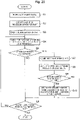
- step S1 the computer appliance 2 populates the part data in step S1, and creates a layout of the processing path for a part in step S2.
- step S3 the computer appliance 2 creates a blank layout of the part.
- step S4 the computer appliance 2 searches for the position of a pierced hole for cutting an outer shape (an outer circumference) of the part, and the position of a pierced hole for forming a hole in the part.
- step S5 the computer appliance 2 determines whether the position of a pierced hole is extracted as a result of the search. In the case where the position of a pierced hole is not extracted (NO), the computer appliance 2 repeats the processes in steps S4 and S5 or in steps S4 to S6. In the case where the position of a pierced hole is extracted in step S5 (YES), the computer appliance 2 acquires, in step S7, the direction of an approach path to be connected to the pierced hole.
- step S8 the computer appliance 2 determines whether the optimum scattering angle is successfully calculated. In the case where the optimum scattering angle is not successfully calculated (NO), the computer appliance 2 proceeds with the process to step S6. In the case where the optimum scattering angle is successfully calculated (YES), the computer appliance 2 adds, in step S10, the auxiliary code indicating the angle direction to which the laser beam is to be displaced to the code (M103) indicating start of cutting, and proceeds with the process to step S6. The processes from steps S7 to S10 are performed for all the pierced holes.
- step S6 the computer appliance 2 determines whether positions of all the pierced holes are already retrieved. In the case where positions of all the pierced holes are not yet retrieved (NO), the computer appliance 2 returns the process to step S4, and in the case where positions of all the pierced holes are already retrieved (YES), the computer appliance 2 ends the process.
- Figure 23 shows an example where the auxiliary code is added at a time of newly creating a processing program.
- the computer appliance 2 may read out a processing program that is already created and stored in the processing program database 60, analyze the processing program, and store the processing program in the processing program database 60 after adding the auxiliary code to a code indicating start of cutting.
- the processing program that is stored in advance in the processing program database 60 may be updated by the processing program where the auxiliary code is added.
- the NC device 50 reads out the processing program in which the auxiliary code is written from the processing program database 60, and reads out the processing condition set by the processing program from the processing condition database 70.
- the NC device 50 controls the laser processing machine 100 such that the sheet metal W is processed according to the processing program and the processing condition that are read out.
- the NC device 50 reads the auxiliary code, and controls the galvano scanner unit 32 such that the laser beam is displaced, within the opening 36a of the nozzle 36, in the angle direction indicated by the auxiliary code.
- the distance by which the laser beam is to be displaced by the galvano scanner unit 32 in the angle direction indicated by the auxiliary code is set in the processing condition indicated by the E number. That is, the distance by which the laser beam is to be displaced at the time of opening of the pierced hole 201 is set in various processing conditions stored in the processing condition database 70.
- the NC device 50 displaces the laser beam by the distance that is set in the processing condition.
- a product 220 shown in Figure 24A is an example of a product in which an opening 230 is to be formed.
- the laser processing machine 100 To fabricate the product 220 by cutting the sheet metal W, the laser processing machine 100 first opens a pierced hole 231 and cuts an approach path 232, and then cuts the sheet metal W to form the opening 230. Next, the laser processing machine 100 opens a pierced hole 221 and cuts an approach path 222, and cuts along an outer circumference of the product 220.
- the opening 230 is small, and thus, if the search region 300 that is a circle having the radius r and centered on a center of the pierced hole 231 is set and the scattering angle region 302 is arranged in the manner shown in Figure 16 , a processing path for the opening 230 is interfered with regardless of the angle direction. Accordingly, the computer appliance 2 is not able to calculate the optimum scattering angle.
- the computer appliance 2 may calculate the optimum scattering angle by changing positions of the pierced hole 231 and the approach path 232 in the manner shown in Figure 24B .
- the computer appliance 2 may calculate an angle of a direction indicated by an arrow as the optimum scattering angle.
- the laser processing machine 100 may increase or decrease a length of the approach path or change an angle of the approach path without changing the positions of the pierced hole and the approach path.
- the optimum scattering angle may be calculated in the following manner instead of being calculated by rotation of the scattering angle region 302 within the search region 300 as described with reference to Figures 15 to 21 .
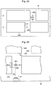
- a blank layout is created on the sheet metal W for rectangular products 241 to 244 having different sizes.
- a pierced hole 251 and an approach path 252 are provided for the product 241.
- a case of calculating the optimum scattering angle at the time of opening the pierced hole 251 will be described as an example.
- Figure 26 is an enlarged view showing a periphery of the pierced hole 251 in Figure 25 .
- the computer appliance 2 forms a rectangle having the width 302w of the scattering angle region 302, positions an edge portion of the rectangle at a center of the pierced hole 251, and rotates the rectangle to each predetermined angle in the circumferential direction around the center of the pierced hole 251. At this time, the computer appliance 2 extends the rectangle at each angle until the rectangle interferes with one of processing paths (including the pierced holes and the approach paths) for the products 242 to 244 other than the product 241.
- Figure 26 shows the rectangle that is extended in three directions.
- a length of the rectangle that is orthogonal to the approach path 252 and that is extended in a direction away from the product 243 is given as D1.
- a length of the rectangle that is extended in an extension direction of the approach path 252 is given as D2.
- a length of the rectangle that is orthogonal to the approach path 252 and that is extended in a direction of the product 243 is given as D3.
- the computer appliance 2 calculates, as the optimum scattering angle, an angle (270 degrees) of the direction orthogonal to the approach path 252 and away from the product 243.
Landscapes
- Engineering & Computer Science (AREA)
- Physics & Mathematics (AREA)
- Optics & Photonics (AREA)
- Plasma & Fusion (AREA)
- Mechanical Engineering (AREA)
- Human Computer Interaction (AREA)
- Manufacturing & Machinery (AREA)
- General Physics & Mathematics (AREA)
- Automation & Control Theory (AREA)
- Geometry (AREA)
- Laser Beam Processing (AREA)
- Numerical Control (AREA)
Abstract
Description
- The present disclosure relates to a processing program creation device, a method for determining a scattering direction of molten metal, a laser processing machine, and a laser processing method.
- A laser processing machine that cuts a sheet metal with a laser beam that is emitted from a laser oscillator is widely used. At the time of the laser processing machine fabricating a product having a predetermined shape by cutting a sheet metal with a laser beam, the laser processing machine opens a hole called a pierced hole in a sheet metal, at a position at an outer part of the product. Subsequent to piercing processing of opening the pierced hole in the sheet metal with a laser beam, the laser processing machine performs approach processing of cutting up to a predetermined position at an outer circumference of the product, and then cuts the sheet metal along the outer circumference of the product.
- Patent Literature 1:
Japanese Patent No. 3761687 - The laser processing machine performs the piercing processing or cuts the sheet metal by irradiating the sheet metal with the laser beam while blowing assist gas according to the material of the sheet metal onto the sheet metal. At the time of the approach processing or cutting along the outer circumference of the product, molten metal generated by the laser beam is blown away by the assist gas to a rear surface side of the sheet metal through a groove that is already cut. However, at the time of the piercing processing, because a groove or a hole is not formed, the molten metal is blown away by the assist gas to an upper surface of the sheet metal to be adhered to a periphery of the pierced hole (see Patent Literature 1).
- The laser beam passes through the center of a circular opening of a nozzle, and the assist gas is blown onto the sheet metal through a periphery of the laser beam. If the sheet metal has a small thickness, the assist gas is applied to the molten metal approximately uniformly in a circumferential direction, and the molten metal is approximately uniformly scattered. However, if the sheet metal has a great thickness, formation of the pierced hole takes a long time, and a phenomenon is possibly caused in which a part being melted subtly moves in a planar direction. Then, the amount of molten metal becomes non-uniform in the circumferential direction by being largely distributed in a predetermined direction, and a greater amount of molten metal is scattered in the direction in which the amount is largely distributed. The direction in which the amount of molten metal is largely distributed is random, and thus, the direction in which a greater amount of molten metal is scattered is random.
- Accordingly, to prevent scattered molten metal from getting adhered to the product, the pierced hole has to be formed at a position that is sufficiently away from the product. At a time of cutting a plurality of products from a sheet metal, a sufficient space for forming the pierced hole has to be provided between adjacent products. Accordingly, the maximum number of products that can be cut out cannot be increased, and the yield cannot be increased. Moreover, metal deposits (spatters) that are molten metal that is adhered and solidified around the pierced hole possibly reduce stability of the approach processing and may cause processing defects.
- Accordingly, if the direction of scattering of the molten metal can be controlled at the time of the piercing processing, and a direction in which the molten metal is most desirably scattered can be automatically determined, yield may be increased and occurrence of processing defects may be made less likely. If the laser processing machine is capable of performing the piercing processing while causing the molten metal to be scattered in the most desirable direction, the yield may be increased and occurrence of processing defects may be made less likely.
- One or more embodiments are directed to providing a processing program creation device that is capable of creating a processing program for enabling control of a direction in which molten metal is to be scattered at a time of piercing processing, a method for determining a scattering direction of the molten metal, the method being capable of automatically determining a most desirable direction in which the molten metal is to be scattered at the time of the piercing processing, and a laser processing machine and a laser processing method that are capable of performing the piercing processing while causing the molten metal to be scattered in the most desirable direction.
- According to a first aspect of the one or more embodiments, there is provided a processing program creation device including: an optimum scattering angle calculator configured to calculate an optimum scattering angle that is an angle most desirable for scattering of molten metal in a search region at a time of piercing processing of opening a pierced hole in a sheet metal to cut the sheet metal and fabricate a first product, the molten metal being generated by melting of the sheet metal, the search region being a circle having a predetermined radius and centered on a center of the pierced hole, the molten metal being not adhered to an approach path extending to the pierced hole and not adhered to a processing path for a second product positioned within the search region at the optimum scattering angle; and a program creator configured to create a processing program by adding an auxiliary code to a code for cutting the sheet metal and fabricating the first product, the auxiliary code indicating that, at a time of the piercing processing on the first product, a position of a laser beam in an opening of a nozzle attached to a tip end of a processing head is displaced in an angle direction of the optimum scattering angle from a center of the opening, the laser beam being emitted from the opening.
- According to a second aspect of the one or more embodiments, there is provided a method for determining a scattering direction of molten metal, the method including, by a computer appliance: setting a search region that is a circle having a predetermined radius and centered on a center of a pierced hole to be opened to cut a sheet metal and fabricate a first product; setting a scattering angle region having a center angle based on a spread angle of spatters determined in advance, the scattering angle region being where molten metal generated by melting of the sheet metal is scattered and spread in a fan shape to be adhered to the sheet metal when a position of a laser beam in an opening of a nozzle attached to a tip end of a processing head is displaced from a center of the opening while assist gas is being blown onto the sheet metal from the opening, the laser beam being emitted from the opening; extracting, from the search region, one or more angle regions at least having an angle range of the scattering angle region, the angle region not interfering with either an approach path extending to the pierced hole or a processing path for a second product positioned in the search region; determining a bisecting angle that is an angle at which a bisector of each angle region of the one or more angle regions is located; and determining, as an optimum scattering angle indicating an angle direction in which the molten metal is to be scattered, an angle, among the bisecting angles of the one or more angle regions, closest to an extension line obtained by extending the approach path in a direction away from the first product.
- According to a third aspect of the one or more embodiments, there is provided a laser processing machine including: a processing head including a nozzle attached to a tip end, the nozzle being for emitting a laser beam from an opening; a moving mechanism configured to move the processing head along a surface of a sheet metal; a beam displacement mechanism configured to displace a position, in the opening, of the laser beam emitted from the opening; an assist gas supply device configured to supply, to the processing head, assist gas to be blown onto the sheet metal from the opening at a time of processing of the sheet metal; and a control device configured to control the beam displacement mechanism at a time of piercing processing of opening a pierced hole in the sheet metal to cut a product based on a processing program, the beam displacement mechanism being controlled such that, in a case where an auxiliary code indicating an angle direction in which the position, in the opening, of the laser beam emitted from the opening is to be displaced from a center of the opening is written in the processing program, the laser beam is displaced in the angle direction indicated by the auxiliary code.
- According to a fourth aspect of the one or more embodiments, there is provided a laser processing method including, by a control device configured to control a laser processing machine: reading an auxiliary code at a time of controlling the laser processing machine based on a processing program such that piercing processing of opening a pierced hole to cut a product is performed on a sheet metal, in a case where the auxiliary code is written in the processing program, the auxiliary code indicating an angle direction in which a laser beam emitted from an opening of a nozzle attached to a tip end of a processing head is to be displaced from a center of the opening; controlling a beam displacement mechanism provided in the laser processing machine in such a manner that the laser beam with which the sheet metal is irradiated at a time of the piercing processing is displaced in the angle direction indicated by the auxiliary code; and controlling an assist gas supply device provided in the laser processing machine in such a manner that assist gas is blown onto the sheet metal from the opening at the time of the piercing processing.
- With the processing program creation device according to the one or more embodiments, a processing program that is capable of controlling the direction of scattering of molten metal at the time of piercing processing may be created. With the method for determining the scattering direction of molten metal according to the one or more embodiments, a direction in which the molten metal is most desirably scattered at the time of the piercing processing may be automatically determined. With the laser processing machine and the laser processing method according to the one or more embodiments, the piercing processing may be performed by causing the molten metal to be scattered in the most desirable direction.
-
- [
Figure 1 ]
Figure 1 is a diagram showing an overall configuration example of a laser processing machine of one or more embodiments. - [
Figure 2 ]
Figure 2 is a perspective view showing an example detailed structure of a collimator unit and a processing head of the laser processing machine of the one or more embodiments. - [
Figure 3A ]
Figure 3A is a side view conceptually showing a piercing processing operation, where a sheet metal has a small thickness. - [
Figure 3B ]
Figure 3B is a side view conceptually showing the piercing processing operation, where the sheet metal has a great thickness. - [
Figure 4 ]
Figure 4 is a partial plan view showing a state where a blank layout of a plurality of rectangular products is created on a sheet metal. - [
Figure 5A ]
Figure 5A is a partial plan view showing a relationship between a position of piercing and a position of a nozzle at a time of typical piercing processing. - [
Figure 5B ]
Figure 5B is a partial plan view showing a first example of a relationship between a position of piercing and a position of a nozzle at a time of piercing processing by a laser processing machine and a laser processing method of the one or more embodiments. - [
Figure 5C ]
Figure 5C is a partial plan view showing a second example of the relationship between the position of piercing and the position of the nozzle at a time of the piercing processing by the laser processing machine and the laser processing method of the one or more embodiments. - [
Figure 6 ]
Figure 6 is a diagram for describing displacement, by a beam displacement mechanism, of an irradiation position of a laser beam on a sheet metal. - [
Figure 7 ]
Figure 7 includes a side view and a plan view showing a manner of scattering of molten metal when the irradiation position of a laser beam on a sheet metal is displaced by the beam displacement mechanism. - [
Figure 8 ]
Figure 8 is a partial plan view showing an example of an adhered state of spatters when the piercing processing is performed by the laser processing machine and the laser processing method of the one or more embodiments. - [
Figure 9 ]
Figure 9 is a diagram giving definitions of a spread angle of spatters that are adhered around a pierced hole and a direction angle difference. - [
Figure 10A ]
Figure 10A is a diagram showing a spread determination degree defined according to the spread angle. - [
Figure 10B ]
Figure 10B is a diagram showing a direction determination degree defined according to the direction angle difference. - [
Figure 11A ]
Figure 11A is a diagram showing a relationship among an amount of displacement of the irradiation position of a laser beam on a sheet metal, the spread determination degree, the direction determination degree, and a rating, where a nozzle with a nozzle diameter of 2 mm is used. - [
Figure 11B ]
Figure 11B is a diagram showing the relationship among the amount of displacement of the irradiation position of a laser beam on a sheet metal, the spread determination degree, the direction determination degree, and the rating, where a nozzle with a nozzle diameter of 3 mm is used. - [
Figure 12 ]
Figure 12 is a block diagram showing a specific configuration example of a computer appliance configuring a processing program creation device of the one or more embodiments. - [
Figure 13 ]
Figure 13 is a diagram showing layout of a processing path for a product (a part). - [
Figure 14 ]
Figure 14 is a diagram showing blank layout of parts on a sheet metal (a sheet). - [
Figure 15 ]
Figure 15 is a diagram showing a search region that is a circle having a predetermined radius and centered on a center of a pierced hole. - [
Figure 16 ]
Figure 16 is a diagram showing a candidate angle region set in the search region. - [
Figure 17 ]
Figure 17 is a diagram showing an example of processing paths for another product present in the candidate angle region. - [
Figure 18 ]
Figure 18 is a diagram showing a state where a plurality of angle regions are extracted from the search region, the angle regions each being a region in which, when a fan-shaped scattering angle region in which molten metal is to be scattered is rotated around the center of the pierced hole, the scattering angle region does not interfere with any of an approach path and the processing paths for the other product. - [
Figure 19 ]
Figure 19 is a diagram showing a process of determining angles at which bisectors of the plurality of angle regions are located. - [
Figure 20 ]
Figure 20 is a diagram showing a state where the angles at which the bisectors of the plurality of angle regions are located are determined. - [
Figure 21 ]
Figure 21 is a diagram showing a state where an angle at which one bisector is located is finally selected, and where the selected angle is determined to be an optimum scattering angle. - [
Figure 22 ]
Figure 22 is a partial schematic view of a processing program in which an auxiliary code indicating the optimum scattering angle is added. - [
Figure 23 ]
Figure 23 is a flowchart showing a process of creating the processing program in which the auxiliary code indicating the optimum scattering angle is added. - [
Figure 24A ]
Figure 24A is a diagram showing an example of a product in which a small opening is to be formed. - [
Figure 24B ]
Figure 24B is a diagram showing a state where positions of a pierced hole and an approach path for forming the opening in the product shown inFigure 24A are changed. - [
Figure 25 ]
Figure 25 is a plan view showing a state where a blank layout of a plurality of rectangular products having different sizes is created on a sheet metal. - [
Figure 26 ]
Figure 26 is a partial enlarged view ofFigure 25 , for describing another calculation method for the optimum scattering angle. - Hereinafter, a processing program creation device, a method for determining a scattering direction of molten metal, a laser processing machine, and a laser processing method of one or more embodiments will be described with reference to the appended drawings. In
Figure 1 , alaser processing machine 100 includes alaser oscillator 10 for generating and emitting a laser beam, alaser processing unit 20, and aprocess fiber 12 for transmitting the laser beam emitted from thelaser oscillator 10 to thelaser processing unit 20. Thelaser processing machine 100 further includes anoperation section 1, acomputer appliance 2 that executes a computer aided manufacturing (CAM) program, anoperation section 40, anNC device 50, aprocessing program database 60, aprocessing condition database 70, and an assistgas supply device 80. - The
operation section 1, thecomputer appliance 2, theprocessing program database 60, and theprocessing condition database 70 may be provided outside thelaser processing machine 100. Theprocessing program database 60 and theprocessing condition database 70 may be connected to theNC device 50 via a network. As described later, thecomputer appliance 2 is a processing program creation device that creates a processing program. TheNC device 50 is an example of a control device for controlling each part of thelaser processing machine 100. - As the
laser oscillator 10, a laser oscillator that emits a laser beam at a predetermined wavelength by amplifying an excitation beam emitted from a laser diode, or a laser oscillator that directly uses a laser beam that is emitted from a laser diode is suitably used. For example, thelaser oscillator 10 is a solid laser oscillator, a fiber laser oscillator, a disk laser oscillator, or a direct diode laser oscillator (a DDL oscillator). - The
laser oscillator 10 emits a 1-µm band laser beam at a wavelength of 900 nm to 1100 nm. When taking the fiber laser oscillator and the DDL oscillator as examples, the fiber laser oscillator emits a laser beam at a wavelength of 1060 nm to 1080 nm, and the DDL oscillator emits a laser beam at a wavelength of 910 nm to 950 nm. - The
laser processing unit 20 includes a processing table 21 on which to place a sheet metal W as a processing target, a gate-typeX-axis carriage 22, a Y-axis carriage 23, acollimator unit 30 fixed to the Y-axis carriage 23, and aprocessing head 35. TheX-axis carriage 22 is freely movable on the processing table 21 in an X-axis direction. The Y-axis carriage 23 is freely movable on theX-axis carriage 22 in a Y-axis direction perpendicular to an X-axis. TheX-axis carriage 22 and the Y-axis carriage 23 function as a moving mechanism for moving theprocessing head 35 along a surface of the sheet metal W, in the X-axis direction, the Y-axis direction, or any combination direction along the X-axis and the Y-axis. - Instead of causing the
processing head 35 to move along the surface of the sheet metal W, the sheet metal W may be moved while fixing a position of theprocessing head 35. It suffices if thelaser processing machine 100 includes a moving mechanism for moving theprocessing head 35 relative to the surface of the sheet metal W. - A
nozzle 36 including acircular opening 36a at a tip end portion is attached to theprocessing head 35, thenozzle 36 being for emitting a laser beam from theopening 36a. The sheet metal W is irradiated with a laser beam that is emitted from theopening 36a of thenozzle 36. - As shown in
Figure 2 , thecollimator unit 30 includes acollimation lens 31 for converting a laser beam that is a divergent beam emitted from theprocess fiber 12 into a parallel beam (a collimated beam). Thecollimator unit 30 also includes agalvano scanner unit 32, and abend mirror 33 for reflecting a laser beam emitted from thegalvano scanner unit 32 downward in a Z-axis direction perpendicular to the X-axis and the Y-axis. Theprocessing head 35 includes a focusinglens 34 for focusing a laser beam reflected by thebend mirror 33, and for irradiating the sheet metal W with the focused laser beam. - The
laser processing machine 100 is aligned such that the laser beam that is emitted from theopening 36a of thenozzle 36 is positioned at a center of theopening 36a. In a standard state, the laser beam is emitted from the center of theopening 36a. Thegalvano scanner unit 32 functions as a beam displacement mechanism for displacing the position, inside theopening 36a, of the laser beam that proceeds through theprocessing head 35 to be emitted from theopening 36a. As a result, thegalvano scanner unit 32 displaces the position, on the sheet metal W, that is to be irradiated with the laser beam to a position that is away from a position immediately below the center of theopening 36a by a predetermined distance. - The
galvano scanner unit 32 is an example of the beam displacement mechanism, and the beam displacement mechanism is not limited to thegalvano scanner unit 32. - The
galvano scanner unit 32 includes ascanning mirror 321 for reflecting the laser beam emitted through thecollimation lens 31, and adriver 322 for rotating thescanning mirror 321 to a predetermined angle. Thegalvano scanner unit 32 also includes ascanning mirror 323 for reflecting the laser beam emitted from thescanning mirror 321, and adriver 324 for rotating thescanning mirror 323 to a predetermined angle. - The
laser processing machine 100 configured in the above manner fabricates a product having a predetermined shape by cutting the sheet metal W with a laser beam emitted from thelaser oscillator 10. At this time, thelaser processing machine 100 performs piercing processing on a position, on the sheet metal W, outside the product with a laser beam, and cuts a linear approach path from a pierced hole to a predetermined position on an outer circumference of the product. Thelaser processing machine 100 fabricates the product by cutting the sheet metal along the outer circumference of the product when the laser beam reaches the predetermined position on the outer circumference of the product that is an end of the approach path on the product side. - Next, a description will be given of a specific method for controlling a direction around a pierced hole in which molten metal is to be adhered, at a time when the piercing processing is performed on the sheet metal W while blowing assist gas onto the sheet metal W. The
laser processing machine 100 may reduce the amount of molten metal adhered to the product side, by controlling the direction around the pierced hole in which the molten metal is to be attached. Thelaser processing machine 100 may also prevent molten metal from getting adhered on the product side around the pierced hole. -
Figures 3A and 3B conceptually show a piercing processing operation performed on the sheet metal W using a typical laser processing method. That is, there is shown a piercing processing operation according to which the center of theopening 36a is positioned immediately above a position where the piercing processing is to be performed, where the sheet metal W is irradiated with the laser beam at immediately below the center of theopening 36a.Figure 3A shows a case where the sheet metal W has a small thickness, andFigure 3B shows a case where the sheet metal W has a great thickness. - In
Figure 3A , at the time of the piercing processing on the sheet metal W, theNC device 50 raises theprocessing head 35 to separate thenozzle 36 from the sheet metal W. Accordingly, a beam waist of the laser beam indicated by a dash-dotted line is positioned above and away from the sheet metal W. Additionally, depending on how a lens is adjusted, the beam waist may be set on the surface of or inside the sheet metal W, and a position of the beam waist may be freely selected. - The sheet metal W is irradiated with the laser beam having passed through the center of the
opening 36a, and metal at an irradiation position is melted into molten metal Wmelt by heat from the laser beam. Assist gas AG supplied to theprocessing head 35 by the assistgas supply device 80 passes through theopening 36a to be blown onto the sheet metal W. The assist gas AG is applied to the molten metal Wmelt approximately uniformly in a circumferential direction, and the molten metal Wmelt is approximately uniformly scattered around a position to be the pierced hole. Additionally, the molten metal Wmelt that is scattered and a metal deposit adhered and solidified on the sheet metal W may both be referred to as a spatter, but in the one or more embodiments, the metal deposit is referred to as the spatter. - In
Figure 3B where the sheet metal W has a great thickness, formation of the pierced hole takes a long time, and a phenomenon is possibly caused in which a part that is immediately below the center of theopening 36a and that is being melted subtly moves in a planar direction. Then, the amount of molten metal Wmelt becomes non-uniform in the circumferential direction by being largely distributed in a predetermined direction, and a greater amount of molten metal Wmelt is scattered in the direction in which the amount is largely distributed. -
Figure 3B shows a state where a greater amount of molten metal Wmelt is scattered in a left direction in the drawing, and more spatters Sp are adhered in the left direction from the position where the pierced hole is to be formed. The direction in which the amount of molten metal Wmelt is to be largely distributed is random, and thus, the direction in which many spatters Sp are to be adhered due to scattering of a great amount of molten metal Wmelt is random. - A case will be considered, as shown in
Figure 4 , where a blank layout of a plurality ofrectangular products 200 is created on the sheet metal W, and where eachproduct 200 is to be cut by thelaser processing machine 100. Thecomputer appliance 2 creates a processing program for performing the piercing processing and opening apierced hole 201 at a position shown inFigure 4 , cutting anapproach path 202 after opening thepierced hole 201, and cutting the sheet metal W along an outer circumference of theproduct 200 after cutting theapproach path 202 up to an edge portion of theproduct 200. The processing program is stored in theprocessing program database 60. - The
NC device 50 reads out the processing program from theprocessing program database 60, and performs selection from a plurality of processing conditions stored in theprocessing condition database 70. TheNC device 50 controls thelaser processing machine 100 such that the sheet metal W is processed based on the processing program that is read out and the processing condition that is selected. - As shown in
Figure 5A , the position where the piercing processing is to be performed to open thepierced hole 201 is set by the processing program to coordinates (X1, Y1) on the sheet metal W. In the case where the laser beam is to be emitted from the center of theopening 36a, theNC device 50 may position theprocessing head 35 such that the center of theopening 36a is positioned at the coordinates (X1, Y1). When the center of theopening 36a is positioned at the coordinates (X1, Y1), the center of theopening 36a is positioned immediately above the position where thepierced hole 201 is to be opened. - In the one or more embodiments, as shown in
Figure 5B , to control the direction in which the molten metal Wmelt is scattered and the spatter Sp is adhered, theNC device 50 positions theprocessing head 35 such that the center of theopening 36a is positioned at the coordinates (X1, Y1). In addition, theNC device 50 changes the angle of thescanning mirror galvano scanner unit 32 such that the position, on the sheet metal W, that is to be irradiated with the laser beam is positioned on an extended line of theapproach path 202 and on a side away from theproduct 200 than the coordinates (X1, Y1). As a result, the position, on the sheet metal W, that is to be irradiated with the laser beam is displaced to a side away from theproduct 200 instead of being immediately below the center of theopening 36a. - Instead of
Figure 5B , theNC device 50 may control theprocessing head 35 and thegalvano scanner unit 32 in the manner shown inFigure 5C . As shown inFigure 5C , theNC device 50 causes theprocessing head 35 to be displaced along theapproach path 202 to be on theproduct 200 side such that the center of theopening 36a is positioned immediately above a position, on theapproach path 202, displaced from the coordinates (X1, Y1) toward theproduct 200. In addition, theNC device 50 changes the angle of thescanning mirror galvano scanner unit 32 such that the position, on the sheet metal W, that is to be irradiated with the laser beam comes at the coordinates (X1, Y1). As a result, the position, on the sheet metal W, that is to be irradiated with the laser beam is displaced not to immediately below the center of theopening 36a, but to a side away from theproduct 200. - In
Figure 6 , a fine solid line that is bent by thebend mirror 33 and that passes through the focusinglens 34 indicates an optical axis of the laser beam in a standard state of thelaser processing machine 100. It is assumed that, due to the action of thegalvano scanner unit 32, the optical axis of the laser beam is displaced from the position indicated by the fine solid line to a position indicated by a thick solid line. When the laser beam reflected by thebend mirror 33 is inclined at an angle θ, the irradiation position of the laser beam on the sheet metal W is displaced by a distance Δs. - Additionally, more specifically, due to the action of the
galvano scanner unit 32 positioned before thebend mirror 33, an angle of the optical axis of the laser beam entering thebend mirror 33 is changed, and the optical axis is shifted from a center of thebend mirror 33. For the sake of simplicity, inFigure 6 , an incident position of the laser beam on thebend mirror 33 is shown to be at a same position before and after the action of thegalvano scanner unit 32. - When a focal length of the focusing
lens 34 is given as an effective focal length (EFL), the distance Δs is calculated by EFL × sinθ. TheNC device 50 may simply tilt the optical axis of the laser beam by the angle θ by thegalvano scanner unit 32 such that the laser beam is displaced by the distance Δs that is set in advance. The distance Δs is a distance that is smaller than a radius of theopening 36a, and is preferably a distance that is equal to or smaller than a maximum distance, where the maximum distance is a distance obtained by subtracting a predetermined margin from the radius of theopening 36a. Additionally, the focal length EFL of the focusinglens 34 is much greater than the distance Δs and is 120 mm, 190 mm or the like, for example, whereas the distance Δs is a distance of several tens to hundreds of micrometers. Accordingly, there is practically no problem in calculating the distance Δs using the EFL without using an optical path length from thebend mirror 33 and without taking into account a refractive index of the focusinglens 34. - Furthermore, to be precise, when the irradiation position of the laser beam on the sheet metal W is displaced by the distance Δs by the
galvano scanner unit 32, the position of the beam waist that is set in a state where the irradiation position of the laser beam is not displaced is shifted in a thickness direction of the sheet metal W. The distance Δs is a distance of several tens to hundreds of micrometers, and thus, a shift in the position of the beam waist is not likely to cause a problem. In the case where the position of the beam waist needs to be adjusted, the focusinglens 34 may simply be displaced in the Z-axis direction, for example. - In
Figure 7, (a) conceptually shows an operation of opening a pierced hole in the sheet metal W by a laser beam that is displaced from the center of theopening 36a to an outer side when seen from a lateral direction of theprocessing head 35, and (b) conceptually shows a state where the sheet metal W is seen from above the sheet metal W. As shown inFigure 7 , the assist gas AG is blown onto the sheet metal W uniformly in the circumferential direction, but the laser beam with which the sheet metal W is irradiated is displaced, and thus, the molten metal Wmelt is scattered in the direction in which the laser beam is displaced. - As in
Figure 3A , (a) inFigure 7 shows a case where the sheet metal W has a small thickness, but the same can be said for a case where the sheet metal W has a great thickness. Even in a case where the sheet metal W has a great thickness, and the amount of molten metal Wmelt is largely distributed on theproduct 200 side, the distance Δs by which the laser beam is displaced on the sheet metal W is much greater than a distance by which the amount of molten metal Wmelt is largely distributed, and thus, the molten metal Wmelt is scattered in the direction in which the laser beam is displaced. - According to the one or more embodiments, as shown in
Figure 8 , control may be performed in such a way that the spatters Sp are adhered to the sheet metal W at around thepierced hole 201, on an opposite side from theproduct 200, and that the spatters Sp are hardly adhered on theproduct 200 side. Accordingly, thepierced hole 201 may be opened near theproduct 200, and thus, a gap D betweenadjacent products 200 as shown inFigure 4 may be reduced. As a result, the one or more embodiments may increase the yield. - According to the one or more embodiments, the spatters Sp are hardly adhered to the
approach path 202, and thus, the approach processing may be stably performed, and possibility of occurrence of processing defects may be reduced. - As shown in
Figure 9 , in a state where the spatters Sp are adhered around thepierced hole 201, an angle of fan-shaped spread of the spatters Sp is given as a spread angle ϕ, and a difference between a direction in which the laser beam is displaced and an angle direction at a center of the spatters Sp that are spread in a fan shape is given as a direction angle difference Δϕ. It can be said that the smaller the spread angle ϕ and the direction angle difference Δϕ, the better controlled the direction of adhesion of the molten metal Wmelt is. - A correspondence between the spread angle ϕ and a spread determination degree is defined as shown in
Figure 10A . For example, the spread angles ϕ of 270 degrees or more, 180 degrees or more and less than 270 degrees, 135 degrees or more and less than 180 degrees, 90 degrees or more and less than 135 degrees, 45 degrees or more and less than 90 degrees, and less than 45 degrees correspond to thespread determination degrees - A correspondence between the direction angle difference Δϕ and a direction determination degree is defined as shown in
Figure 10B . For example, the direction angle differences Δϕ of 135 degrees or more, 90 degrees or more and less than 135 degrees, 77.5 degrees or more and less than 90 degrees, 45 degrees or more and less than 77.5 degrees, 22.5 degrees or more and less than 45 degrees, and less than 22.5 degrees correspond to thedirection determination degrees - In
Figures 11A and 11B , a distance by which the position, on the sheet metal W, that is to be irradiated with the laser beam is displaced from the position immediately below the center of theopening 36a is given as an amount of displacement. The distance Δs described inFigure 6 is the amount of displacement. The spread determination degree and the direction determination degree inFigures 11A and 11B each indicate an average value where the piercing processing is performed three times. -
Figure 11A shows a relationship among the amount of displacement, the spread determination degree, the direction determination degree, and a rating, where the piercing processing is performed on the sheet metal W that is stainless steel having a thickness of 6 mm, by using thenozzle 36 with a nozzle diameter of 2 mm and with a laser power of 4 kW. - As shown in
Figure 11A , in the case where the nozzle diameter is 2 mm, up to the amount of displacement of 25 µm, the spread determination degree and the direction determination degree are small and the rating is "poor." When the amount of displacement is 50 µm to 100 µm, the spread determination degree and the direction determination degree are both increased, and the rating is "fair." When the amount of displacement is 150 µm or more, the spread determination degree and the direction determination degree each take a value of 5 or a value close to 5, and the rating is "good." In the case of using thenozzle 36 with a nozzle diameter of 2 mm, the amount of displacement is preferably 50 µm or more, and is, more preferably, 150 µm or more. -
Figure 11B shows the relationship among the amount of displacement, the spread determination degree, the direction determination degree, and the rating, where the piercing processing is performed on the sheet metal W under the same condition as inFigure 11A , but with thenozzle 36 with a nozzle diameter of 3 mm. - As shown in
Figure 11B , in the case where the nozzle diameter is 3 mm, up to the amount of displacement of 50 µm, the spread determination degree and the direction determination degree are both 0 and the rating is "poor." When the amount of displacement is 250 µm, the spread determination degree and the direction determination degree are both increased, and the rating is "fair." When the amount of displacement is 450 µm or 650 µm, the spread determination degree takes a value of around 4 and the direction determination degree takes a value of 5, and the rating is "good." In the case of using thenozzle 36 with a nozzle diameter of 3 mm, the amount of displacement is preferably 250 µm or more, and is, more preferably, 450 µm or more. - The
NC device 50 may displace the position, on the sheet metal W, that is to be irradiated with the laser beam from the position immediately below the center of theopening 36a, by the amount of displacement that is optimally set according to conditions including the nozzle diameter, a shape of thenozzle 36, a nozzle gap at the time of the piercing processing, a gas pressure of the assist gas and the like. - Now, in the example described above, at the time of opening the
pierced hole 201, the laser beam with which the sheet metal W is irradiated is displaced along theapproach path 202, in a direction away from theproduct 200. Depending on a position of a processing path (a cutting path) for another product present near thepierced hole 201, the laser beam is possibly more desirably displaced in a direction different from the direction along theapproach path 202. - Accordingly, an optimum scattering angle indicating a most desirable direction in which the molten metal is to be scattered is desirably automatically determined at the time of the piercing processing, and the laser beam is desirably displaced in the direction of the optimum scattering angle that is determined.
- The
computer appliance 2 that is the processing program creation device creates a processing program for enabling automatic determination of the optimum scattering angle and displacement of the laser beam in the direction of the determined optimum scattering angle. A specific configuration of thecomputer appliance 2 will be described with reference toFigure 12 , and layout of a processing path for a product (a part) and blank layout of parts on the sheet metal W (a sheet) will be described with reference toFigures 13 and 14 . - As shown in
Figure 12 , thecomputer appliance 2 includes anautomatic layout section 211, an automaticblank layout section 212, an optimumscattering angle calculator 213, and aprogram creator 214. Theautomatic layout section 211 to theprogram creator 214 may be configured by a CAM program. Part data that is CAD data created by a computer appliance, not shown, that executes a computer aided design (CAD) program is input to theautomatic layout section 211. The part data is shape data of one product such as theproduct 200. Thecomputer appliance 2 may be the computer appliance that executes the CAD program. That is, thecomputer appliance 2 may be a CAD/CAM appliance that executes the CAD and CAM programs. - As shown in
Figure 13 , when taking theproduct 200 shown inFigure 4 as an example, theautomatic layout section 211 creates layout data by laying out a processing path for cutting theapproach path 202 subsequent to the piercing processing of opening thepierced hole 201 and then cutting the sheet metal W along anouter circumference 200L of theproduct 200. - Sheet data indicating the sheet metal W, and instruction data indicating the number of
products 200 to be cut from the sheet metal W are input to the automaticblank layout section 212. The number ofproducts 200 to be cut is instructed by theoperation section 1. For example, in the case where the number of pieces is nine, the automaticblank layout section 212 creates blank layout data for cutting out nineproducts 200 from the sheet metal W, as shown inFigure 14 , based on the layout data for the sheet metal W shown inFigure 13 . - The optimum
scattering angle calculator 213 calculates the optimum scattering angle of molten metal for when opening each piercedhole 201, based on the blank layout data created by the automaticblank layout section 212. Theprogram creator 214 creates a processing program by including an auxiliary code indicating the optimum scattering angle calculated by the optimumscattering angle calculator 213. The processing program is transmitted to and stored in theprocessing program database 60. - A method of the one or more embodiments for determining the scattering direction of molten metal will be described with reference to
Figures 15 to 21 , the method being for calculating the optimum scattering angle and determining the direction in which molten metal is to be scattered. The optimumscattering angle calculator 213 sets asearch region 300 that is a circle having a predetermined radius r and centered on the center of thepierced hole 201. The radius r is 10 mm, for example. The optimumscattering angle calculator 213 defines an angle in a circumferential direction of thesearch region 300, where the position of the approach path is at 0 degrees. In the example shown inFigure 15 , 0 to 360 degrees are set in a counterclockwise direction, where theapproach path 202 is seen from thepierced hole 201. - As shown in
Figure 16 , the optimumscattering angle calculator 213 sets anangle region 301 between 90 degrees and 270 degrees in thesearch region 300, for example, as an angle region to be a candidate of a scattering angle in which molten metal is to be scattered. In the following, theangle region 301 will be referred to as acandidate angle region 301. In order to ensure that the spatters Sp are hardly adhered to theapproach path 202 as described above, thecandidate angle region 301 is desirably the angle region between 90 degrees and 270 degrees. However, an operator may operate theoperation section 1 to set the angles of thecandidate angle region 301 to other than between 90 degrees and 270 degrees. Thecandidate angle region 301 has to be an angle region that does not include theapproach path 202. - As described with reference to
Figures 9 ,10A ,11A and 11B , the spread angle ϕ in which the spatters Sp are to be spread in a fan shape may be set to a predetermined angle. For example, in a case where the nozzle diameter is 2 mm and the amount of displacement is 250 mm or more, the spread angle ϕ may be made smaller than 45 degrees. Specifically what angle is to be adopted as the spread angle ϕ can be determined in advance by an experiment. - As shown in
Figure 16 , an angle region having the spread angle ϕ is taken as ascattering angle region 302 where molten metal is to be scattered. Alength 302w of a chord connecting both ends of a circular arc of thescattering angle region 302 is taken as a width of thescattering angle region 302. Here, a center angle of thescattering angle region 302 is the spread angle ϕ, but an angle that is wider than the spread angle ϕ may alternatively be made the center angle of thescattering angle region 302 by taking the direction angle difference Δϕ into account. It suffices if the center angle of thescattering angle region 302 is set based on the spread angle ϕ. - In the case where the processing path for another product is included in the
candidate angle region 301, thescattering angle region 302 has to be set to have an angle that does not include the processing path for the other product. The spread angle ϕ that is set in advance or the spread angle ϕ that is input by the operator through theoperation section 1 is input to the optimumscattering angle calculator 213. Additionally, thelength 302w of the chord may be input instead of the spread angle ϕ. - It is assumed, as shown in
Figure 17 , that processingpaths candidate angle region 301. When theproduct 200 is taken as a first product, the other product is a second product. Theprocessing paths - According to the blank layout data shown in
Figure 14 , theprocessing paths candidate angle region 301, a case is given as an example where theprocessing paths candidate angle region 301. The number of processing paths for another product included in thecandidate angle region 301 is one or more. - The optimum
scattering angle calculator 213 rotates the fan-shaped scattering angle region 302 (seeFigure 16 ) around the center of thepierced hole 201, and extracts an angle region that does not interfere with any of theapproach path 202 and theprocessing paths - As shown in
Figure 18 , the optimumscattering angle calculator 213 extracts, from thesearch region 300, fan-shaped angle regions ArA, ArB and ArC. The angle regions ArA, ArB and ArC are each an angle region at least having an angle range of thescattering angle region 302. In this case, three angle regions are extracted, but one or more angle regions may be extracted. - When the
scattering angle region 302 is rotated counterclockwise, the angle region ArA is an angle region from an angle greater than 0 degrees at which thescattering angle region 302 does not contact theapproach path 202 to an angle just short of contact with a point P01a on theprocessing path 401. The angle region ArB is an angle region from an angle at which thescattering angle region 302 does not contact a point P01b on theprocessing path 401 to an angle just short of contact with a point P02a on theprocessing path 402. The angle region ArC is an angle region from an angle at which thescattering angle region 302 does not contact a point P02b on theprocessing path 402 to an angle less than 360 degrees at which thescattering angle region 302 does not contact theapproach path 202. - As shown in
Figure 19 , the optimumscattering angle calculator 213 arranges thescattering angle region 302 at both end portions, in an angle direction, within the angle regions ArA, ArB and ArC. The optimumscattering angle calculator 213 determines angles AgA1 and AgA2 where bisectors of two scatteringangle regions 302 arranged in the angle region ArA are located. The optimumscattering angle calculator 213 determines angles AgB1 and AgB2 where bisectors of two scatteringangle regions 302 arranged in the angle region ArB are located. The optimumscattering angle calculator 213 determines angles AgC1 and AgC2 where bisectors of two scatteringangle regions 302 arranged in the angle region ArC are located. - As shown in
Figure 20 , the optimumscattering angle calculator 213 determines an angle AgA where a bisector of a fan-shaped region between the angles AgA1 and AgA2 is located, and determines an angle AgB where a bisector of a fan-shaped region between the angles AgB1 and AgB2 is located. Neither of the angles AgC1 and AgC2 shown inFigure 19 is included in thecandidate angle region 301, and thus, the optimumscattering angle calculator 213 does not determine an angle where a bisector of a fan-shaped region between the angles AgC1 and AgC2 is located, and the angle region ArC is excluded from targets for which the angle where a bisector is located is to be determined. The angles AgA and AgB are angles where the bisectors of the fan-shaped angle regions ArA and ArB are located. In the following, the angles AgA and AgB will be referred to as bisecting angles AgA and AgB. - When the bisecting angle AgA or AgB is less than 90 degrees, the optimum
scattering angle calculator 213 corrects the same to 90 degrees; when the bisecting angle AgA or AgB is between 90 degrees and 270 degrees and is within thecandidate angle region 301, the optimumscattering angle calculator 213 does not perform correction; when the bisecting angle AgA or AgB is more than 270 degrees, the optimumscattering angle calculator 213 corrects the same to 270 degrees. InFigure 21 , AgA' is a corrected bisecting angle that is the bisecting angle AgA shown inFigure 20 after being corrected to 90 degrees. The bisecting angle AgB is not corrected. - Lastly, the optimum
scattering angle calculator 213 determines, as the optimum scattering angle, from the corrected bisecting angle AgA' and the bisecting angle AgB, an angle closest to an extended line obtained by extending theapproach path 202 in a direction away from the product 200 (that is, an angle closest to 180 degrees). InFigure 21 , the bisecting angle AgB is determined to be the optimum scattering angle. Here, the optimum scattering angle is assumed to be 190 degrees. The optimum scattering angle indicates the direction angle at which the laser beam positioned at the center of theopening 36a of thenozzle 36 is to be displaced. - Additionally, in the case where none of the angles of the bisectors of the two
scattering angle regions 302 set in each angle region in thesearch region 300 are within thecandidate angle region 301, the process for calculating the optimum scattering angle is ended. In the case where 90 degrees and 270 degrees are determined as the bisecting angle(s) or the corrected bisecting angle(s) of two angle regions set in thesearch region 300, the optimumscattering angle calculator 213 may take either 90 degrees or 270 degrees as the optimum scattering angle. In the case where one of 90 degrees and 270 degrees is a bisecting angle that is not corrected and the other is a corrected bisecting angle, the bisecting angle that is not corrected may be taken as the optimum scattering angle. - The method for extracting the angle regions ArA, ArB and ArC from the
search region 300, and the method for determining the respective bisecting angles AgA and AgB of the angle regions ArA and ArB are not limited to the methods described above. The optimumscattering angle calculator 213 may extract an angle region that does not interfere with any of theapproach path 202 and theprocessing paths pierced hole 201. The optimumscattering angle calculator 213 may take an angle where the bisector of the extracted angle region is located as the bisecting angle. - Additionally, in this case, if the angle of an extracted angle region is smaller than the spread angle ϕ that is the angle of the
scattering angle region 302, such an angle region should be excluded from target angle regions for which the bisecting angle is to be determined. - In the case where a processing path for another product, such as the
processing path candidate angle region 301, the optimum scattering angle is calculated to be 180 degrees. Accordingly, the laser beam positioned at the center of theopening 36a is displaced to be on the extended line obtained by extending theapproach path 202 in a direction away from theproduct 200. -
Figure 22 shows, in a simplified manner, an example of the processing program that is created by theprogram creator 214 and that includes a G code. M103 is a code indicating start of cutting, and a code starting with G, immediately before the code M103, indicates the position of the pierced hole. For example, theprogram creator 214 adds the auxiliary code indicating the optimum scattering angle after the code M103. In the example described above, the optimum scattering angle is 190 degrees, and thus, an auxiliary code "K190" is added to the code M103. - In the example shown in
Figure 22 , a processing condition indicated by an E number E4 indicated by E004 is set. The processing condition may be automatically selected according to the material of the sheet metal W, or may be selected by the operator through theoperation section 1. - The process of calculating of the optimum scattering angle and creating the processing program by the
computer appliance 2 will be described again with reference to the flowchart shown inFigure 23 . When the process is started, thecomputer appliance 2 populates the part data in step S1, and creates a layout of the processing path for a part in step S2. In step S3, thecomputer appliance 2 creates a blank layout of the part. In step S4, thecomputer appliance 2 searches for the position of a pierced hole for cutting an outer shape (an outer circumference) of the part, and the position of a pierced hole for forming a hole in the part. - In step S5, the
computer appliance 2 determines whether the position of a pierced hole is extracted as a result of the search. In the case where the position of a pierced hole is not extracted (NO), thecomputer appliance 2 repeats the processes in steps S4 and S5 or in steps S4 to S6. In the case where the position of a pierced hole is extracted in step S5 (YES), thecomputer appliance 2 acquires, in step S7, the direction of an approach path to be connected to the pierced hole. - In step S8, the
computer appliance 2 determines whether the optimum scattering angle is successfully calculated. In the case where the optimum scattering angle is not successfully calculated (NO), thecomputer appliance 2 proceeds with the process to step S6. In the case where the optimum scattering angle is successfully calculated (YES), thecomputer appliance 2 adds, in step S10, the auxiliary code indicating the angle direction to which the laser beam is to be displaced to the code (M103) indicating start of cutting, and proceeds with the process to step S6. The processes from steps S7 to S10 are performed for all the pierced holes. - In step S6, the
computer appliance 2 determines whether positions of all the pierced holes are already retrieved. In the case where positions of all the pierced holes are not yet retrieved (NO), thecomputer appliance 2 returns the process to step S4, and in the case where positions of all the pierced holes are already retrieved (YES), thecomputer appliance 2 ends the process. -
Figure 23 shows an example where the auxiliary code is added at a time of newly creating a processing program. Thecomputer appliance 2 may read out a processing program that is already created and stored in theprocessing program database 60, analyze the processing program, and store the processing program in theprocessing program database 60 after adding the auxiliary code to a code indicating start of cutting. In this case, the processing program that is stored in advance in theprocessing program database 60 may be updated by the processing program where the auxiliary code is added. - Referring back to
Figure 1 , theNC device 50 reads out the processing program in which the auxiliary code is written from theprocessing program database 60, and reads out the processing condition set by the processing program from theprocessing condition database 70. TheNC device 50 controls thelaser processing machine 100 such that the sheet metal W is processed according to the processing program and the processing condition that are read out. - At the time of opening the
pierced hole 201 in the sheet metal W, if the auxiliary code is written, theNC device 50 reads the auxiliary code, and controls thegalvano scanner unit 32 such that the laser beam is displaced, within theopening 36a of thenozzle 36, in the angle direction indicated by the auxiliary code. - The distance by which the laser beam is to be displaced by the
galvano scanner unit 32 in the angle direction indicated by the auxiliary code is set in the processing condition indicated by the E number. That is, the distance by which the laser beam is to be displaced at the time of opening of thepierced hole 201 is set in various processing conditions stored in theprocessing condition database 70. In the case where the auxiliary code is added at a time of opening thepierced hole 201 in the sheet metal W, theNC device 50 displaces the laser beam by the distance that is set in the processing condition. - A
product 220 shown inFigure 24A is an example of a product in which anopening 230 is to be formed. To fabricate theproduct 220 by cutting the sheet metal W, thelaser processing machine 100 first opens apierced hole 231 and cuts anapproach path 232, and then cuts the sheet metal W to form theopening 230. Next, thelaser processing machine 100 opens apierced hole 221 and cuts anapproach path 222, and cuts along an outer circumference of theproduct 220. In the example shown inFigure 24A , theopening 230 is small, and thus, if thesearch region 300 that is a circle having the radius r and centered on a center of thepierced hole 231 is set and thescattering angle region 302 is arranged in the manner shown inFigure 16 , a processing path for theopening 230 is interfered with regardless of the angle direction. Accordingly, thecomputer appliance 2 is not able to calculate the optimum scattering angle. - In such a case, the
computer appliance 2 may calculate the optimum scattering angle by changing positions of thepierced hole 231 and theapproach path 232 in the manner shown inFigure 24B . InFigure 24B , thecomputer appliance 2 may calculate an angle of a direction indicated by an arrow as the optimum scattering angle. - Instead of changing the positions of the pierced hole and the approach path, the
laser processing machine 100 may increase or decrease a length of the approach path or change an angle of the approach path without changing the positions of the pierced hole and the approach path. - The optimum scattering angle may be calculated in the following manner instead of being calculated by rotation of the
scattering angle region 302 within thesearch region 300 as described with reference toFigures 15 to 21 . In the example shown inFigure 25 , a blank layout is created on the sheet metal W forrectangular products 241 to 244 having different sizes. Apierced hole 251 and anapproach path 252 are provided for theproduct 241. A case of calculating the optimum scattering angle at the time of opening thepierced hole 251 will be described as an example. -
Figure 26 is an enlarged view showing a periphery of thepierced hole 251 inFigure 25 . Thecomputer appliance 2 forms a rectangle having thewidth 302w of thescattering angle region 302, positions an edge portion of the rectangle at a center of thepierced hole 251, and rotates the rectangle to each predetermined angle in the circumferential direction around the center of thepierced hole 251. At this time, thecomputer appliance 2 extends the rectangle at each angle until the rectangle interferes with one of processing paths (including the pierced holes and the approach paths) for theproducts 242 to 244 other than theproduct 241. -
Figure 26 shows the rectangle that is extended in three directions. A length of the rectangle that is orthogonal to theapproach path 252 and that is extended in a direction away from theproduct 243 is given as D1. A length of the rectangle that is extended in an extension direction of theapproach path 252 is given as D2. A length of the rectangle that is orthogonal to theapproach path 252 and that is extended in a direction of theproduct 243 is given as D3. When comparing the lengths D1 to D3, the length D1 is the longest, and the length D1 is the longest at every angle in the circumferential direction around the center of thepierced hole 251. Accordingly, thecomputer appliance 2 calculates, as the optimum scattering angle, an angle (270 degrees) of the direction orthogonal to theapproach path 252 and away from theproduct 243. - The present invention is not limited to the one or more embodiments described above, and various modifications may be made without departing from the scope of the gist of the present invention.
- The present application claims the benefit of priority to
Japanese Patent Application No. 2019-105098
Claims (8)
- A processing program creation device comprising:an optimum scattering angle calculator configured to calculate an optimum scattering angle that is an angle most desirable for scattering of molten metal in a search region at a time of piercing processing of opening a pierced hole in a sheet metal to cut the sheet metal and fabricate a first product, the molten metal being generated by melting of the sheet metal, the search region being a circle having a predetermined radius and centered on a center of the pierced hole, the molten metal being not adhered to an approach path extending to the pierced hole and not adhered to a processing path for a second product positioned within the search region at the optimum scattering angle; anda program creator configured to create a processing program by adding an auxiliary code to a code for cutting the sheet metal and fabricating the first product, the auxiliary code indicating that, at a time of the piercing processing on the first product, a position of a laser beam in an opening of a nozzle attached to a tip end of a processing head is displaced in an angle direction of the optimum scattering angle from a center of the opening, the laser beam being emitted from the opening.
- The processing program creation device according to claim 1, wherein the program creator adds the auxiliary code to a code indicating opening of the pierced hole in the sheet metal and indicating start of cutting of the sheet metal.
- A method for determining a scattering direction of molten metal, the method comprising, by a computer appliance:setting a search region that is a circle having a predetermined radius and centered on a center of a pierced hole to be opened to cut a sheet metal and fabricate a first product;setting a scattering angle region having a center angle based on a spread angle of spatters determined in advance, the scattering angle region being where molten metal generated by melting of the sheet metal is scattered and spread in a fan shape to be adhered to the sheet metal when a position of a laser beam in an opening of a nozzle attached to a tip end of a processing head is displaced from a center of the opening while assist gas is being blown onto the sheet metal from the opening, the laser beam being emitted from the opening;extracting, from the search region, one or more angle regions at least having an angle range of the scattering angle region, the angle region not interfering with either an approach path extending to the pierced hole or a processing path for a second product positioned in the search region;determining a bisecting angle that is an angle at which a bisector of each angle region of the one or more angle regions is located; anddetermining, as an optimum scattering angle indicating an angle direction in which the molten metal is to be scattered, an angle, among the bisecting angles of the one or more angle regions, closest to an extension line obtained by extending the approach path in a direction away from the first product.
- The method for determining a scattering direction of molten metal according to claim 3, further comprising, by the computer appliance:setting a candidate angle region in the search region, the candidate angle region having a predetermined angle range not including the approach path; andexcluding, from a target angle region for which the bisecting angle is to be determined, an angle region having the angle range of the scattering angle region and positioned outside the candidate angle region.
- A laser processing machine comprising:a processing head including a nozzle attached to a tip end, the nozzle being for emitting a laser beam from an opening;a moving mechanism configured to move the processing head along a surface of a sheet metal;a beam displacement mechanism configured to displace a position, in the opening, of the laser beam emitted from the opening;an assist gas supply device configured to supply, to the processing head, assist gas to be blown onto the sheet metal from the opening at a time of processing of the sheet metal; anda control device configured to control the beam displacement mechanism at a time of piercing processing of opening a pierced hole in the sheet metal to cut a product based on a processing program, the beam displacement mechanism being controlled such that, in a case where an auxiliary code indicating an angle direction in which the position, in the opening, of the laser beam emitted from the opening is to be displaced from a center of the opening is written in the processing program, the laser beam is displaced in the angle direction indicated by the auxiliary code.
- The laser processing machine according to claim 5, whereina processing condition including a distance by which the laser beam is to be displaced at the time of the piercing processing is set in the processing program, andthe control device controls the beam displacement mechanism such that the laser beam is displaced in the angle direction indicated by the auxiliary code, by the distance included in the processing condition.
- A laser processing method comprising, by a control device configured to control a laser processing machine:reading an auxiliary code at a time of controlling the laser processing machine based on a processing program such that piercing processing of opening a pierced hole to cut a product is performed on a sheet metal, in a case where the auxiliary code is written in the processing program, the auxiliary code indicating an angle direction in which a laser beam emitted from an opening of a nozzle attached to a tip end of a processing head is to be displaced from a center of the opening;controlling a beam displacement mechanism provided in the laser processing machine in such a manner that the laser beam with which the sheet metal is irradiated at a time of the piercing processing is displaced in the angle direction indicated by the auxiliary code; andcontrolling an assist gas supply device provided in the laser processing machine in such a manner that assist gas is blown onto the sheet metal from the opening at the time of the piercing processing.
- The laser processing method according to claim 7, whereina processing condition including a distance by which the laser beam is to be displaced at the time of the piercing processing is set in the processing program, andthe control device controls the beam displacement mechanism such that the laser beam is displaced in the angle direction indicated by the auxiliary code, by the distance included in the processing condition.
Applications Claiming Priority (2)
| Application Number | Priority Date | Filing Date | Title |
|---|---|---|---|
| JP2019105098A JP6854317B2 (en) | 2019-06-05 | 2019-06-05 | Machining program creation device and method for determining the scattering direction of molten metal |
| PCT/JP2020/021040 WO2020246354A1 (en) | 2019-06-05 | 2020-05-28 | Processing program creation device, method for determining scattering direction of molten metal, laser processing machine, and laser processing method |
Publications (3)
| Publication Number | Publication Date |
|---|---|
| EP3981538A1 true EP3981538A1 (en) | 2022-04-13 |
| EP3981538A4 EP3981538A4 (en) | 2022-07-27 |
| EP3981538B1 EP3981538B1 (en) | 2023-08-23 |
Family
ID=73648296
Family Applications (1)
| Application Number | Title | Priority Date | Filing Date |
|---|---|---|---|
| EP20818465.5A Active EP3981538B1 (en) | 2019-06-05 | 2020-05-28 | Processing program creation device and method for determining scattering direction of molten metal |
Country Status (4)
| Country | Link |
|---|---|
| US (1) | US12304003B2 (en) |
| EP (1) | EP3981538B1 (en) |
| JP (1) | JP6854317B2 (en) |
| WO (1) | WO2020246354A1 (en) |
Families Citing this family (2)
| Publication number | Priority date | Publication date | Assignee | Title |
|---|---|---|---|---|
| WO2022244649A1 (en) * | 2021-05-20 | 2022-11-24 | 株式会社アマダ | Laser machining device and laser machining method |
| JP7584658B2 (en) * | 2021-07-16 | 2024-11-15 | 三菱電機株式会社 | Laser processing device and laser processing method |
Family Cites Families (10)
| Publication number | Priority date | Publication date | Assignee | Title |
|---|---|---|---|---|
| JP3292021B2 (en) * | 1996-01-30 | 2002-06-17 | 三菱電機株式会社 | Laser processing method and laser processing apparatus |
| JPH11788A (en) * | 1997-04-11 | 1999-01-06 | Amada Co Ltd | Laser beam machining method and nozzle of laser beam machine using this machining method |
| JP3761687B2 (en) | 1997-09-25 | 2006-03-29 | 株式会社アマダ | Method for removing material adhering melt during piercing |
| JP4037152B2 (en) * | 2002-04-11 | 2008-01-23 | 三菱電機株式会社 | Laser processing head of laser processing equipment |
| DE102008030783B3 (en) * | 2008-06-28 | 2009-08-13 | Trumpf Werkzeugmaschinen Gmbh + Co. Kg | Process for laser beam angle cutting of workpiece involving ultrasonic gas cutting stream generally useful in laser cutting operations gives higher quality products at increased cutting speeds |
| JP5570459B2 (en) * | 2011-03-10 | 2014-08-13 | 三菱電機株式会社 | Laser processing apparatus and laser processing method |
| JP6292922B2 (en) * | 2014-02-25 | 2018-03-14 | 株式会社アマダホールディングス | Laser processing method and laser processing apparatus |
| JP6116757B2 (en) * | 2014-04-10 | 2017-04-19 | 三菱電機株式会社 | Laser processing equipment |
| JP2019105098A (en) | 2017-12-13 | 2019-06-27 | 日鉄日新製鋼株式会社 | Coated metal plate for wall material, and wall material using the same |
| JP6538911B1 (en) * | 2018-03-12 | 2019-07-03 | 株式会社アマダホールディングス | Laser processing machine and laser processing method |
-
2019
- 2019-06-05 JP JP2019105098A patent/JP6854317B2/en active Active
-
2020
- 2020-05-28 EP EP20818465.5A patent/EP3981538B1/en active Active
- 2020-05-28 WO PCT/JP2020/021040 patent/WO2020246354A1/en not_active Ceased
- 2020-05-28 US US17/615,355 patent/US12304003B2/en active Active
Also Published As
| Publication number | Publication date |
|---|---|
| US20220226933A1 (en) | 2022-07-21 |
| JP2020196036A (en) | 2020-12-10 |
| US12304003B2 (en) | 2025-05-20 |
| EP3981538A4 (en) | 2022-07-27 |
| WO2020246354A1 (en) | 2020-12-10 |
| JP6854317B2 (en) | 2021-04-07 |
| EP3981538B1 (en) | 2023-08-23 |
Similar Documents
| Publication | Publication Date | Title |
|---|---|---|
| TWI714792B (en) | A method of laser processing of a metallic material, as well as a machine and a computer program for the implementation of said method | |
| US10994374B2 (en) | Laser processing machine and laser processing method | |
| EP3766630B1 (en) | Laser processing machine and laser processing method | |
| JP2019155404A (en) | Laser processor and laser processing method | |
| EP3981538B1 (en) | Processing program creation device and method for determining scattering direction of molten metal | |
| EP3871825B1 (en) | Laser beam machine, laser beam machining method | |
| EP3871827B1 (en) | Laser machining device and laser machining method | |
| EP3865244B1 (en) | Laser processing machine and laser processing method | |
| EP3831527B1 (en) | Laser machining device and laser machining method | |
| US20250381622A1 (en) | Laser cutting method | |
| EP3819069B1 (en) | Laser machining method | |
| EP4603222A1 (en) | Laser machining apparatus, laser machining method, machining program creation method, and machining program configuration method | |
| EP4342619A1 (en) | Laser machining device and laser machining method | |
| JP2020116599A (en) | Laser beam machining apparatus and laser beam machining method | |
| EP3871826B1 (en) | Laser beam machine, method for setting machining conditions, and control device for laser beam machine |
Legal Events
| Date | Code | Title | Description |
|---|---|---|---|
| STAA | Information on the status of an ep patent application or granted ep patent |
Free format text: STATUS: THE INTERNATIONAL PUBLICATION HAS BEEN MADE |
|
| PUAI | Public reference made under article 153(3) epc to a published international application that has entered the european phase |
Free format text: ORIGINAL CODE: 0009012 |
|
| STAA | Information on the status of an ep patent application or granted ep patent |
Free format text: STATUS: REQUEST FOR EXAMINATION WAS MADE |
|
| 17P | Request for examination filed |
Effective date: 20211126 |
|
| AK | Designated contracting states |
Kind code of ref document: A1 Designated state(s): AL AT BE BG CH CY CZ DE DK EE ES FI FR GB GR HR HU IE IS IT LI LT LU LV MC MK MT NL NO PL PT RO RS SE SI SK SM TR |
|
| A4 | Supplementary search report drawn up and despatched |
Effective date: 20220624 |
|
| RIC1 | Information provided on ipc code assigned before grant |
Ipc: B23K 101/18 20060101ALI20220621BHEP Ipc: B23K 26/70 20140101ALI20220621BHEP Ipc: B23K 26/142 20140101ALI20220621BHEP Ipc: B23K 26/06 20140101ALI20220621BHEP Ipc: G05B 19/4093 20060101ALI20220621BHEP Ipc: B23K 26/382 20140101ALI20220621BHEP Ipc: B23K 26/38 20140101ALI20220621BHEP Ipc: B23K 26/04 20140101ALI20220621BHEP Ipc: B23K 26/00 20140101AFI20220621BHEP |
|
| DAV | Request for validation of the european patent (deleted) | ||
| DAX | Request for extension of the european patent (deleted) | ||
| STAA | Information on the status of an ep patent application or granted ep patent |
Free format text: STATUS: EXAMINATION IS IN PROGRESS |
|
| 17Q | First examination report despatched |
Effective date: 20221130 |
|
| GRAP | Despatch of communication of intention to grant a patent |
Free format text: ORIGINAL CODE: EPIDOSNIGR1 |
|
| STAA | Information on the status of an ep patent application or granted ep patent |
Free format text: STATUS: GRANT OF PATENT IS INTENDED |
|
| INTG | Intention to grant announced |
Effective date: 20230503 |
|
| RIN1 | Information on inventor provided before grant (corrected) |
Inventor name: MURAKAMI, TAKUYA |
|
| P01 | Opt-out of the competence of the unified patent court (upc) registered |
Effective date: 20230527 |
|
| GRAS | Grant fee paid |
Free format text: ORIGINAL CODE: EPIDOSNIGR3 |
|
| GRAA | (expected) grant |
Free format text: ORIGINAL CODE: 0009210 |
|
| STAA | Information on the status of an ep patent application or granted ep patent |
Free format text: STATUS: THE PATENT HAS BEEN GRANTED |
|
| AK | Designated contracting states |
Kind code of ref document: B1 Designated state(s): AL AT BE BG CH CY CZ DE DK EE ES FI FR GB GR HR HU IE IS IT LI LT LU LV MC MK MT NL NO PL PT RO RS SE SI SK SM TR |
|
| REG | Reference to a national code |
Ref country code: GB Ref legal event code: FG4D |
|
| REG | Reference to a national code |
Ref country code: CH Ref legal event code: EP |
|
| REG | Reference to a national code |
Ref country code: DE Ref legal event code: R096 Ref document number: 602020016390 Country of ref document: DE |
|
| REG | Reference to a national code |
Ref country code: IE Ref legal event code: FG4D |
|
| REG | Reference to a national code |
Ref country code: LT Ref legal event code: MG9D |
|
| REG | Reference to a national code |
Ref country code: NL Ref legal event code: MP Effective date: 20230823 |
|
| REG | Reference to a national code |
Ref country code: AT Ref legal event code: MK05 Ref document number: 1602007 Country of ref document: AT Kind code of ref document: T Effective date: 20230823 |
|
| PG25 | Lapsed in a contracting state [announced via postgrant information from national office to epo] |
Ref country code: GR Free format text: LAPSE BECAUSE OF FAILURE TO SUBMIT A TRANSLATION OF THE DESCRIPTION OR TO PAY THE FEE WITHIN THE PRESCRIBED TIME-LIMIT Effective date: 20231124 |
|
| PG25 | Lapsed in a contracting state [announced via postgrant information from national office to epo] |
Ref country code: IS Free format text: LAPSE BECAUSE OF FAILURE TO SUBMIT A TRANSLATION OF THE DESCRIPTION OR TO PAY THE FEE WITHIN THE PRESCRIBED TIME-LIMIT Effective date: 20231223 |
|
| PG25 | Lapsed in a contracting state [announced via postgrant information from national office to epo] |
Ref country code: SE Free format text: LAPSE BECAUSE OF FAILURE TO SUBMIT A TRANSLATION OF THE DESCRIPTION OR TO PAY THE FEE WITHIN THE PRESCRIBED TIME-LIMIT Effective date: 20230823 Ref country code: RS Free format text: LAPSE BECAUSE OF FAILURE TO SUBMIT A TRANSLATION OF THE DESCRIPTION OR TO PAY THE FEE WITHIN THE PRESCRIBED TIME-LIMIT Effective date: 20230823 Ref country code: PT Free format text: LAPSE BECAUSE OF FAILURE TO SUBMIT A TRANSLATION OF THE DESCRIPTION OR TO PAY THE FEE WITHIN THE PRESCRIBED TIME-LIMIT Effective date: 20231226 Ref country code: NO Free format text: LAPSE BECAUSE OF FAILURE TO SUBMIT A TRANSLATION OF THE DESCRIPTION OR TO PAY THE FEE WITHIN THE PRESCRIBED TIME-LIMIT Effective date: 20231123 Ref country code: NL Free format text: LAPSE BECAUSE OF FAILURE TO SUBMIT A TRANSLATION OF THE DESCRIPTION OR TO PAY THE FEE WITHIN THE PRESCRIBED TIME-LIMIT Effective date: 20230823 Ref country code: LV Free format text: LAPSE BECAUSE OF FAILURE TO SUBMIT A TRANSLATION OF THE DESCRIPTION OR TO PAY THE FEE WITHIN THE PRESCRIBED TIME-LIMIT Effective date: 20230823 Ref country code: LT Free format text: LAPSE BECAUSE OF FAILURE TO SUBMIT A TRANSLATION OF THE DESCRIPTION OR TO PAY THE FEE WITHIN THE PRESCRIBED TIME-LIMIT Effective date: 20230823 Ref country code: IS Free format text: LAPSE BECAUSE OF FAILURE TO SUBMIT A TRANSLATION OF THE DESCRIPTION OR TO PAY THE FEE WITHIN THE PRESCRIBED TIME-LIMIT Effective date: 20231223 Ref country code: HR Free format text: LAPSE BECAUSE OF FAILURE TO SUBMIT A TRANSLATION OF THE DESCRIPTION OR TO PAY THE FEE WITHIN THE PRESCRIBED TIME-LIMIT Effective date: 20230823 Ref country code: GR Free format text: LAPSE BECAUSE OF FAILURE TO SUBMIT A TRANSLATION OF THE DESCRIPTION OR TO PAY THE FEE WITHIN THE PRESCRIBED TIME-LIMIT Effective date: 20231124 Ref country code: FI Free format text: LAPSE BECAUSE OF FAILURE TO SUBMIT A TRANSLATION OF THE DESCRIPTION OR TO PAY THE FEE WITHIN THE PRESCRIBED TIME-LIMIT Effective date: 20230823 Ref country code: AT Free format text: LAPSE BECAUSE OF FAILURE TO SUBMIT A TRANSLATION OF THE DESCRIPTION OR TO PAY THE FEE WITHIN THE PRESCRIBED TIME-LIMIT Effective date: 20230823 |
|
| PG25 | Lapsed in a contracting state [announced via postgrant information from national office to epo] |
Ref country code: PL Free format text: LAPSE BECAUSE OF FAILURE TO SUBMIT A TRANSLATION OF THE DESCRIPTION OR TO PAY THE FEE WITHIN THE PRESCRIBED TIME-LIMIT Effective date: 20230823 |
|
| PG25 | Lapsed in a contracting state [announced via postgrant information from national office to epo] |
Ref country code: ES Free format text: LAPSE BECAUSE OF FAILURE TO SUBMIT A TRANSLATION OF THE DESCRIPTION OR TO PAY THE FEE WITHIN THE PRESCRIBED TIME-LIMIT Effective date: 20230823 |
|
| PG25 | Lapsed in a contracting state [announced via postgrant information from national office to epo] |
Ref country code: SM Free format text: LAPSE BECAUSE OF FAILURE TO SUBMIT A TRANSLATION OF THE DESCRIPTION OR TO PAY THE FEE WITHIN THE PRESCRIBED TIME-LIMIT Effective date: 20230823 Ref country code: RO Free format text: LAPSE BECAUSE OF FAILURE TO SUBMIT A TRANSLATION OF THE DESCRIPTION OR TO PAY THE FEE WITHIN THE PRESCRIBED TIME-LIMIT Effective date: 20230823 Ref country code: ES Free format text: LAPSE BECAUSE OF FAILURE TO SUBMIT A TRANSLATION OF THE DESCRIPTION OR TO PAY THE FEE WITHIN THE PRESCRIBED TIME-LIMIT Effective date: 20230823 Ref country code: EE Free format text: LAPSE BECAUSE OF FAILURE TO SUBMIT A TRANSLATION OF THE DESCRIPTION OR TO PAY THE FEE WITHIN THE PRESCRIBED TIME-LIMIT Effective date: 20230823 Ref country code: DK Free format text: LAPSE BECAUSE OF FAILURE TO SUBMIT A TRANSLATION OF THE DESCRIPTION OR TO PAY THE FEE WITHIN THE PRESCRIBED TIME-LIMIT Effective date: 20230823 Ref country code: CZ Free format text: LAPSE BECAUSE OF FAILURE TO SUBMIT A TRANSLATION OF THE DESCRIPTION OR TO PAY THE FEE WITHIN THE PRESCRIBED TIME-LIMIT Effective date: 20230823 Ref country code: SK Free format text: LAPSE BECAUSE OF FAILURE TO SUBMIT A TRANSLATION OF THE DESCRIPTION OR TO PAY THE FEE WITHIN THE PRESCRIBED TIME-LIMIT Effective date: 20230823 |
|
| REG | Reference to a national code |
Ref country code: DE Ref legal event code: R097 Ref document number: 602020016390 Country of ref document: DE |
|
| PG25 | Lapsed in a contracting state [announced via postgrant information from national office to epo] |
Ref country code: IT Free format text: LAPSE BECAUSE OF FAILURE TO SUBMIT A TRANSLATION OF THE DESCRIPTION OR TO PAY THE FEE WITHIN THE PRESCRIBED TIME-LIMIT Effective date: 20230823 |
|
| PLBE | No opposition filed within time limit |
Free format text: ORIGINAL CODE: 0009261 |
|
| STAA | Information on the status of an ep patent application or granted ep patent |
Free format text: STATUS: NO OPPOSITION FILED WITHIN TIME LIMIT |
|
| 26N | No opposition filed |
Effective date: 20240524 |
|
| PG25 | Lapsed in a contracting state [announced via postgrant information from national office to epo] |
Ref country code: SI Free format text: LAPSE BECAUSE OF FAILURE TO SUBMIT A TRANSLATION OF THE DESCRIPTION OR TO PAY THE FEE WITHIN THE PRESCRIBED TIME-LIMIT Effective date: 20230823 |
|
| PG25 | Lapsed in a contracting state [announced via postgrant information from national office to epo] |
Ref country code: BG Free format text: LAPSE BECAUSE OF FAILURE TO SUBMIT A TRANSLATION OF THE DESCRIPTION OR TO PAY THE FEE WITHIN THE PRESCRIBED TIME-LIMIT Effective date: 20230823 |
|
| PG25 | Lapsed in a contracting state [announced via postgrant information from national office to epo] |
Ref country code: BG Free format text: LAPSE BECAUSE OF FAILURE TO SUBMIT A TRANSLATION OF THE DESCRIPTION OR TO PAY THE FEE WITHIN THE PRESCRIBED TIME-LIMIT Effective date: 20230823 |
|
| REG | Reference to a national code |
Ref country code: CH Ref legal event code: PL |
|
| PG25 | Lapsed in a contracting state [announced via postgrant information from national office to epo] |
Ref country code: MC Free format text: LAPSE BECAUSE OF FAILURE TO SUBMIT A TRANSLATION OF THE DESCRIPTION OR TO PAY THE FEE WITHIN THE PRESCRIBED TIME-LIMIT Effective date: 20230823 |
|
| PG25 | Lapsed in a contracting state [announced via postgrant information from national office to epo] |
Ref country code: LU Free format text: LAPSE BECAUSE OF NON-PAYMENT OF DUE FEES Effective date: 20240528 |
|
| GBPC | Gb: european patent ceased through non-payment of renewal fee |
Effective date: 20240528 |
|
| PG25 | Lapsed in a contracting state [announced via postgrant information from national office to epo] |
Ref country code: MC Free format text: LAPSE BECAUSE OF FAILURE TO SUBMIT A TRANSLATION OF THE DESCRIPTION OR TO PAY THE FEE WITHIN THE PRESCRIBED TIME-LIMIT Effective date: 20230823 Ref country code: LU Free format text: LAPSE BECAUSE OF NON-PAYMENT OF DUE FEES Effective date: 20240528 Ref country code: CH Free format text: LAPSE BECAUSE OF NON-PAYMENT OF DUE FEES Effective date: 20240531 |
|
| REG | Reference to a national code |
Ref country code: BE Ref legal event code: MM Effective date: 20240531 |
|
| PG25 | Lapsed in a contracting state [announced via postgrant information from national office to epo] |
Ref country code: IE Free format text: LAPSE BECAUSE OF NON-PAYMENT OF DUE FEES Effective date: 20240528 |
|
| PG25 | Lapsed in a contracting state [announced via postgrant information from national office to epo] |
Ref country code: BE Free format text: LAPSE BECAUSE OF NON-PAYMENT OF DUE FEES Effective date: 20240531 |
|
| PG25 | Lapsed in a contracting state [announced via postgrant information from national office to epo] |
Ref country code: FR Free format text: LAPSE BECAUSE OF NON-PAYMENT OF DUE FEES Effective date: 20240531 |
|
| PG25 | Lapsed in a contracting state [announced via postgrant information from national office to epo] |
Ref country code: GB Free format text: LAPSE BECAUSE OF NON-PAYMENT OF DUE FEES Effective date: 20240528 |
|
| PGFP | Annual fee paid to national office [announced via postgrant information from national office to epo] |
Ref country code: DE Payment date: 20250521 Year of fee payment: 6 |
|
| PG25 | Lapsed in a contracting state [announced via postgrant information from national office to epo] |
Ref country code: CY Free format text: LAPSE BECAUSE OF FAILURE TO SUBMIT A TRANSLATION OF THE DESCRIPTION OR TO PAY THE FEE WITHIN THE PRESCRIBED TIME-LIMIT; INVALID AB INITIO Effective date: 20200528 |
|
| PG25 | Lapsed in a contracting state [announced via postgrant information from national office to epo] |
Ref country code: HU Free format text: LAPSE BECAUSE OF FAILURE TO SUBMIT A TRANSLATION OF THE DESCRIPTION OR TO PAY THE FEE WITHIN THE PRESCRIBED TIME-LIMIT; INVALID AB INITIO Effective date: 20200528 |