EP3981361A1 - Blank and method for the manufacture of at least one molded part - Google Patents
Blank and method for the manufacture of at least one molded part Download PDFInfo
- Publication number
- EP3981361A1 EP3981361A1 EP21212268.3A EP21212268A EP3981361A1 EP 3981361 A1 EP3981361 A1 EP 3981361A1 EP 21212268 A EP21212268 A EP 21212268A EP 3981361 A1 EP3981361 A1 EP 3981361A1
- Authority
- EP
- European Patent Office
- Prior art keywords
- base
- blank
- region
- regions
- blank according
- Prior art date
- Legal status (The legal status is an assumption and is not a legal conclusion. Google has not performed a legal analysis and makes no representation as to the accuracy of the status listed.)
- Granted
Links
Images


Classifications
-
- A—HUMAN NECESSITIES
- A61—MEDICAL OR VETERINARY SCIENCE; HYGIENE
- A61C—DENTISTRY; APPARATUS OR METHODS FOR ORAL OR DENTAL HYGIENE
- A61C13/00—Dental prostheses; Making same
- A61C13/0003—Making bridge-work, inlays, implants or the like
- A61C13/0022—Blanks or green, unfinished dental restoration parts
-
- A—HUMAN NECESSITIES
- A61—MEDICAL OR VETERINARY SCIENCE; HYGIENE
- A61C—DENTISTRY; APPARATUS OR METHODS FOR ORAL OR DENTAL HYGIENE
- A61C13/00—Dental prostheses; Making same
-
- A—HUMAN NECESSITIES
- A61—MEDICAL OR VETERINARY SCIENCE; HYGIENE
- A61C—DENTISTRY; APPARATUS OR METHODS FOR ORAL OR DENTAL HYGIENE
- A61C13/00—Dental prostheses; Making same
- A61C13/0003—Making bridge-work, inlays, implants or the like
- A61C13/0004—Computer-assisted sizing or machining of dental prostheses
-
- A—HUMAN NECESSITIES
- A61—MEDICAL OR VETERINARY SCIENCE; HYGIENE
- A61C—DENTISTRY; APPARATUS OR METHODS FOR ORAL OR DENTAL HYGIENE
- A61C13/00—Dental prostheses; Making same
- A61C13/0003—Making bridge-work, inlays, implants or the like
- A61C13/0006—Production methods
-
- A—HUMAN NECESSITIES
- A61—MEDICAL OR VETERINARY SCIENCE; HYGIENE
- A61C—DENTISTRY; APPARATUS OR METHODS FOR ORAL OR DENTAL HYGIENE
- A61C13/00—Dental prostheses; Making same
- A61C13/08—Artificial teeth; Making same
- A61C13/083—Porcelain or ceramic teeth
-
- A—HUMAN NECESSITIES
- A61—MEDICAL OR VETERINARY SCIENCE; HYGIENE
- A61C—DENTISTRY; APPARATUS OR METHODS FOR ORAL OR DENTAL HYGIENE
- A61C8/00—Means to be fixed to the jaw-bone for consolidating natural teeth or for fixing dental prostheses thereon; Dental implants; Implanting tools
- A61C8/0012—Means to be fixed to the jaw-bone for consolidating natural teeth or for fixing dental prostheses thereon; Dental implants; Implanting tools characterised by the material or composition, e.g. ceramics, surface layer, metal alloy
Definitions
- the invention relates to a blank for the manufacture of at least one molded body, in particular a dental reconstruction.
- the invention also embraces a method for the production of at least one molded part, in particular a dental restoration, or a section thereof through material-removing processing.
- Blanks made of ceramic materials have been successfully applied for manufacturing molded bodies, in particular dental restorations through material-removing machining using multi-axis machine tools such as milling machines. Blanks consisting of other materials, such as plastics, composites or metals, are also used for that purpose.
- An object of the present invention is to provide a blank that allows the wear on the tool to be reduced when the blank is machined.
- a further object is to enable optimal usage of the material considering the shape of the desired molded part.
- a blank which consists essentially of a base and at least one region that emanates therefrom and projects above the base, from which the molded body or at least a part of it can be obtained.
- the blank comprises a plurality of regions projecting either above one side of the base or above both sides of the base.
- the blank does not have a disc geometry or cuboid geometry with uniform thickness that does not vary, but rather comprises a carrier layer that forms the base and regions that emanate and project therefrom, to yield the advantage that the material requirement for the blank is reduced so that molded parts can be produced at lower cost, in particular dental reconstructions such as bridges, frameworks, crowns, caps, veneers, inlays or onlays.
- the at least one region projecting above the base has preferably one of the following geometries - cuboid, cylindrical, conical or curved shape.
- the different geometries enable an optimal adaptation to the shape or geometries of the molded bodies to be produced.
- regions can project from the base that are different in terms of area to such an extent that from a single blank, molded bodies of different geometries can be derived through material-removing working, with optimal material usage.
- the base has a thickness B where B ⁇ 10 mm, preferably B ⁇ 5 mm, in particular 1.5 mm ⁇ B ⁇ 4 mm.
- the ratio of the thickness B of the base to the height H of the region projecting above the base is 1:15 ⁇ B:H ⁇ 1:1, in particular 1:10 ⁇ B:H ⁇ 1:6.
- the regions have dimensions that enable the production of a dental framework, a crown, a partial crown, a bridge, a dental arch, a cap, a veneer, an abutment, a pin construction, an inlay and/or an onlay.
- the blank or at least a region of it comprises or contains at least one material from the group of ceramic materials such as zirconium dioxide, glass ceramic, feldspar ceramic, metallic materials such as titanium, CoCr alloy, organic materials such as thermoplastic material, in particular PMMA or PEEK, composite materials, glass fiber-reinforced plastic.
- ceramic materials such as zirconium dioxide, glass ceramic, feldspar ceramic, metallic materials such as titanium, CoCr alloy, organic materials such as thermoplastic material, in particular PMMA or PEEK, composite materials, glass fiber-reinforced plastic.
- the blank is preferably made from zirconium dioxide to which yttrium oxide (Y 2 O 3 ), calcium oxide (CaO), magnesium oxide (MgO) and/or cerium oxide (CeO 2 ), in particular yttrium oxide, has been added.
- Y 2 O 3 yttrium oxide
- CaO calcium oxide
- MgO magnesium oxide
- CeO 2 cerium oxide
- the at least one region projecting above the base, optionally incorporating the materials of the base comprises sections that differ in terms of their material properties, such as strength and/or translucency and/or coloration and/or fluorescence.
- the base is made from a material that is different from that of the regions from which the molded bodies are derived. So, for example, the base material may be a plastic.
- the base can have openings in which the regions, for instance, are glued in.
- the regions are surrounded by the base material during manufacturing of the base by e.g. injection molding.
- the regions are lamellar enclosed by the base material.
- the invention relates also to a method for the production of at least one molded body, in particular a dental restoration, or a section thereof through machining by material-removing from a region of a blank that projects from a base, wherein the machining commences through removal of material from the circumferential surface of the region.
- machining it is thereby in particular provided for the machining to be carried out using a milling tool that has an axis of rotation and that at least at the beginning of material removal there is a relative movement between the milling tool and the region transverse, preferably perpendicular, to the axis of rotation.
- the blank itself can be produced through pressing, casting, additive methods, forming or mechanical working methods.
- a blank with a base from which a number of regions emanate, wherein the regions are separated by a section of the base.
- the blanks can preferably comprise ceramic materials such as zirconium dioxide, glass ceramic, feldspar ceramic, to name just a few ceramic materials.
- the blanks may in particular be of zirconium dioxide to which yttrium oxide, calcium oxide, magnesium oxide and/or cerium oxide is added, but in particular yttrium oxide stabilized zirconia.
- Suitable materials also include metallic materials such as titanium or CoCr alloys.
- the blanks may also be made from organic materials, optionally filled, in particular thermoplastic materials such as polymethylmethacrylate (PMMA) or polyetheretherketone (PEEK).
- thermoplastic materials such as polymethylmethacrylate (PMMA) or polyetheretherketone (PEEK).
- Disc-shaped blanks are generally used to manufacture dental molded bodies / reconstructions through material-removing working.
- the dental restorations can be in the form of dental frameworks, crowns, partial crowns, bridges, caps, veneers, abutments, pin constructions, inlays and/or onlays or dental arches, but this is by no means an exhaustive list.
- a plurality of corresponding molded bodies may be obtained, depending on the diameter of the blanks.
- Previously known blanks exhibit a uniform thickness across the regions from which the molded bodies are obtained through machining.
- a disadvantage here is that there are relatively high material losses since the material between the individual molded bodies is not utilized.
- a further particular disadvantage here is that the milling tool rotating about an axis of rotation and moving in the direction of the axis of rotation at least at the start of the processing of a molded part removes material from the blank with only a small part of the tool surface so that there is a high load on the tool. The wear is consequently relatively high.
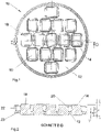
- Figures 1 to 3 thus show a first embodiment of a disc-shaped blank 10 that in the diagrams has a circular geometry, which has regions of different thickness.
- the blank 10 in principle comprises a base 12 and regions that emanate therefrom, indicated by way of example by the reference numbers 14, 16 and 18.
- the regions 14, 16, 18 do not just project above one side of the base 12, but rather extend on both sides, as clearly shown in the sectional view in Fig. 2 . This, however, is not a required characteristic. Rather, the invention relates also to a blank wherein regions project only from one side of the base.
- the height of the regions 14, 16, 18 is aligned with the molded bodies to be produced.
- a machining tool acts from the side on the elevated regions 14, 16, 18, i.e., a relative movement to the elevation 14, 16, 18 substantially perpendicular to the axis of rotation of the tool is achieved.
- This possibility relates not just to the regions 14, 16, 18, that are arranged in the perimeter of the blank 10, but also to the regions surrounded by a plurality of projecting regions, as there is a distance between these, as can be seen in the sectional view of Figure 2 .
- a corresponding distance is indicated by way of example by the reference number 20.
- the invention provides for the elevated regions 14, 16, 18 emanating from the base to extend non-symmetrically on both sides of the base, so that without change to holders, that normally accommodate blanks with the usual milling machines, blanks according to the invention can be fixed in a processing machine.
- a circumferential border 22 is provided in the exemplary embodiment which limits the blank 10 peripherally.
- the edge 22 has an L-shaped cross-section and may be an integral part of the blank 10.
- the edge 22 can of course also be a separately-produced element that is connected to the blank, i.e., in particular with the base 12, for instance through gluing.
- the base 12 has a thickness B that is preferred in the range 1 to 10 mm, in particular between 1 mm and 5 mm, and especially preferred in the range 1.5 mm to 3 mm.
- the region 14, 16, 18 projecting above the upper side of the base 12 has a height V1 and the region projecting from the underside of the base 12 has a height V2.
- V1 + V2 + B should preferably lie between 15 mm and 25 mm.
- the exemplary embodiment shown in Figures 4 to 6 differs from that in Figures 1 to 3 in that the blank 100, which also has a circular geometry, has regions that extend differently in terms of area.
- the blank 100 which also has a circular geometry, has regions that extend differently in terms of area.
- four regions 114, 116, 118 and 120 are indicated.
- the regions 114, 116, 118, 120 extend - as with the embodiment illustrated by Figures 1 to 3 - on both sides of a base 112, as can be seen in the sectional view A-A ( Fig. 5 ).
- the blank 100 and thus the base 112 are also delimited by a circumferential edge 122.
- the description for Figures 1 to 3 applies here too.
- regions of different area extend from the base 112
- molded bodies of different geometries and sizes can be obtained.
- a four to five unit bridge can be machined from the region 114
- a front dental arch from the region 116 a three unit bridge from the region 118 and from the other equally dimensioned regions 120 single tooth restorations such as inlays, onlays, crowns etc. can be machined.
- the teaching according to the invention enables material to be spared. This saving may be up to 40% if, for example, the base 12, 112 has a thickness of 2 mm and the total thickness of the blank, in the regions from which the projections 14, 16, 18, 114, 116, 118, 120 emanate from the base 12, 112, is 18 mm.
- the blanks 10, 100 according to the invention can be held in the usual holders since it is not necessary to change the profile and the dimensions of the edge 22, 122.
- the limb 23, 123 of the edge 22, 122 which extends parallel to the plane defined by the blank 10, 100 and which in the sectional views extends horizontally, is an extension of the base 12, 112, as can be seen in the sectional views.
- the blanks 10, 100 can be produced, for example, through additive methods by pressing, casting, forming or mechanical manufacturing methods.
- the material of the blank at least in the region of the elevations 14, 16, 18, 114, 116, 118, 120 in particular over its height to have a different composition / different material characteristics to, for instance, obtain a color gradation that corresponds to that of natural teeth for the crowns or bridges. produced.
Landscapes
- Health & Medical Sciences (AREA)
- General Health & Medical Sciences (AREA)
- Veterinary Medicine (AREA)
- Oral & Maxillofacial Surgery (AREA)
- Dentistry (AREA)
- Epidemiology (AREA)
- Life Sciences & Earth Sciences (AREA)
- Public Health (AREA)
- Animal Behavior & Ethology (AREA)
- Engineering & Computer Science (AREA)
- Ceramic Engineering (AREA)
- Orthopedic Medicine & Surgery (AREA)
- Chemical & Material Sciences (AREA)
- Manufacturing & Machinery (AREA)
- Dental Preparations (AREA)
- Dental Prosthetics (AREA)
- Dental Tools And Instruments Or Auxiliary Dental Instruments (AREA)
Abstract
Description
- The invention relates to a blank for the manufacture of at least one molded body, in particular a dental reconstruction.
- The invention also embraces a method for the production of at least one molded part, in particular a dental restoration, or a section thereof through material-removing processing.
- Blanks, made of ceramic materials have been successfully applied for manufacturing molded bodies, in particular dental restorations through material-removing machining using multi-axis machine tools such as milling machines. Blanks consisting of other materials, such as plastics, composites or metals, are also used for that purpose.
- To produce high-precision molded parts by CAD/CAM methods it is necessary to take the wear of the machining tool into consideration. In the prior art blanks are machined in such a way that the tool is fed in an axial direction. This results in a high load on the tool and thus to wear, which means that it is necessary to change the tool frequently.
- An object of the present invention is to provide a blank that allows the wear on the tool to be reduced when the blank is machined. A further object is to enable optimal usage of the material considering the shape of the desired molded part.
- Moreover, a method for the production of a molded body is presented which is characterized by a reduction in the wear of the tool.
- To achieve the aim a blank is proposed which consists essentially of a base and at least one region that emanates therefrom and projects above the base, from which the molded body or at least a part of it can be obtained. Preferably the blank comprises a plurality of regions projecting either above one side of the base or above both sides of the base.
- In contrast to the prior art, the blank does not have a disc geometry or cuboid geometry with uniform thickness that does not vary, but rather comprises a carrier layer that forms the base and regions that emanate and project therefrom, to yield the advantage that the material requirement for the blank is reduced so that molded parts can be produced at lower cost, in particular dental reconstructions such as bridges, frameworks, crowns, caps, veneers, inlays or onlays.
- In addition to material savings there is further the advantage that right from the start of the machining operation regions can be machined from their sides, i.e., relative movement in a transverse direction between the tool's axis of rotation and the projecting region, in particular perpendicular to the axis of rotation, is possible. This results in a lower load on the tool so that wear is reduced.
- The at least one region projecting above the base has preferably one of the following geometries - cuboid, cylindrical, conical or curved shape. The different geometries enable an optimal adaptation to the shape or geometries of the molded bodies to be produced. Thus, for the production of dental reconstructions regions can project from the base that are different in terms of area to such an extent that from a single blank, molded bodies of different geometries can be derived through material-removing working, with optimal material usage.
- In particular it is provided for the base to have a thickness B where B ≤ 10 mm, preferably B ≤ 5 mm, in particular 1.5 mm ≤ B ≤ 4 mm.
- In a further development of the invention the ratio of the thickness B of the base to the height H of the region projecting above the base is 1:15 ≤ B:H ≤ 1:1, in particular 1:10 ≤ B:H ≤ 1:6.
- In terms of area the regions have dimensions that enable the production of a dental framework, a crown, a partial crown, a bridge, a dental arch, a cap, a veneer, an abutment, a pin construction, an inlay and/or an onlay.
- In a preferred embodiment the blank or at least a region of it comprises or contains at least one material from the group of ceramic materials such as zirconium dioxide, glass ceramic, feldspar ceramic, metallic materials such as titanium, CoCr alloy, organic materials such as thermoplastic material, in particular PMMA or PEEK, composite materials, glass fiber-reinforced plastic.
- The blank is preferably made from zirconium dioxide to which yttrium oxide (Y2O3), calcium oxide (CaO), magnesium oxide (MgO) and/or cerium oxide (CeO2), in particular yttrium oxide, has been added.
- Further, there is the possibility of producing dental prostheses in particular which in terms of color gradation, or in terms of their material properties, correspond to a natural tooth. The invention is therefore characterized in that the at least one region projecting above the base, optionally incorporating the materials of the base, comprises sections that differ in terms of their material properties, such as strength and/or translucency and/or coloration and/or fluorescence.
- There is no departure from the invention if the base is made from a material that is different from that of the regions from which the molded bodies are derived. So, for example, the base material may be a plastic. The base can have openings in which the regions, for instance, are glued in. However, there is also the possibility that the regions are surrounded by the base material during manufacturing of the base by e.g. injection molding. Corresponding to the thickness of the base the regions are lamellar enclosed by the base material.
- The invention relates also to a method for the production of at least one molded body, in particular a dental restoration, or a section thereof through machining by material-removing from a region of a blank that projects from a base, wherein the machining commences through removal of material from the circumferential surface of the region.
- It is thereby in particular provided for the machining to be carried out using a milling tool that has an axis of rotation and that at least at the beginning of material removal there is a relative movement between the milling tool and the region transverse, preferably perpendicular, to the axis of rotation.
- The blank itself can be produced through pressing, casting, additive methods, forming or mechanical working methods.
- Particularly, use is made of a blank with a base from which a number of regions emanate, wherein the regions are separated by a section of the base.
- Further details, advantages and features of the invention may be derived not only from the claims, and the features to be taken from them - either alone and/or in combination - but also from the examples described below and illustrated by drawings.
-
- Fig. 1
- A top view of a first embodiment of a blank,
- Fig. 2
- A section along the line D-D in
Fig. 1 , - Fig. 3
- The blank according to
Fig. 1 viewed from the bottom, - Fig. 4
- A top view of a second embodiment of a blank,
- Fig. 5
- A section along the line A-A in
Fig. 4 , and - Fig. 6
- The blank according to
Fig. 4 viewed from the bottom. - The teaching according to the invention is described in more detail with reference to the figures, on the basis of which molded bodies, in particular dental molded parts, can be produced in a material-saving manner from blanks, in particular through milling. At the same time this yields the advantage that the wear on the tool used for machining of the blank can be reduced.
- The blanks can preferably comprise ceramic materials such as zirconium dioxide, glass ceramic, feldspar ceramic, to name just a few ceramic materials.
- The blanks may in particular be of zirconium dioxide to which yttrium oxide, calcium oxide, magnesium oxide and/or cerium oxide is added, but in particular yttrium oxide stabilized zirconia.
- Suitable materials also include metallic materials such as titanium or CoCr alloys.
- The blanks may also be made from organic materials, optionally filled, in particular thermoplastic materials such as polymethylmethacrylate (PMMA) or polyetheretherketone (PEEK).
- Composite materials or glass fiber-reinforced plastic are also possible.
- Disc-shaped blanks are generally used to manufacture dental molded bodies / reconstructions through material-removing working. The dental restorations can be in the form of dental frameworks, crowns, partial crowns, bridges, caps, veneers, abutments, pin constructions, inlays and/or onlays or dental arches, but this is by no means an exhaustive list. A plurality of corresponding molded bodies may be obtained, depending on the diameter of the blanks.
- Previously known blanks exhibit a uniform thickness across the regions from which the molded bodies are obtained through machining. A disadvantage here is that there are relatively high material losses since the material between the individual molded bodies is not utilized. A further particular disadvantage here is that the milling tool rotating about an axis of rotation and moving in the direction of the axis of rotation at least at the start of the processing of a molded part removes material from the blank with only a small part of the tool surface so that there is a high load on the tool. The wear is consequently relatively high.
- All of these disadvantages are avoided with the blanks according to the invention.
-
Figures 1 to 3 thus show a first embodiment of a disc-shaped blank 10 that in the diagrams has a circular geometry, which has regions of different thickness. - Thus the blank 10 in principle comprises a
base 12 and regions that emanate therefrom, indicated by way of example by thereference numbers regions base 12, but rather extend on both sides, as clearly shown in the sectional view inFig. 2 . This, however, is not a required characteristic. Rather, the invention relates also to a blank wherein regions project only from one side of the base. - The height of the
regions - To obtain desired molded bodies from the
regions regions elevated regions elevation regions Figure 2 . A corresponding distance is indicated by way of example by thereference number 20. - In particular the invention provides for the
elevated regions circumferential border 22 is provided in the exemplary embodiment which limits the blank 10 peripherally. In this example theedge 22 has an L-shaped cross-section and may be an integral part of the blank 10. Theedge 22 can of course also be a separately-produced element that is connected to the blank, i.e., in particular with thebase 12, for instance through gluing. - As can be seen from the sectional view in
Figure 2 , thebase 12 has a thickness B that is preferred in the range 1 to 10 mm, in particular between 1 mm and 5 mm, and especially preferred in the range 1.5 mm to 3 mm. Theregion base 12 has a height V1 and the region projecting from the underside of thebase 12 has a height V2. V1 + V2 + B should preferably lie between 15 mm and 25 mm. In particular the ratio of the thickness B of the base 12 to the total height H (= V1 + V2 + B) of theparticular region - From the bottom view of the blank 10 it is similarly clear that the
regions base 12. - The exemplary embodiment shown in
Figures 4 to 6 differs from that inFigures 1 to 3 in that the blank 100, which also has a circular geometry, has regions that extend differently in terms of area. By way of example, fourregions regions Figures 1 to 3 - on both sides of abase 112, as can be seen in the sectional view A-A (Fig. 5 ). The blank 100 and thus the base 112 are also delimited by acircumferential edge 122. The description forFigures 1 to 3 applies here too. - Since regions of different area extend from the
base 112, it follows that molded bodies of different geometries and sizes can be obtained. For example, a four to five unit bridge can be machined from theregion 114, a front dental arch from theregion 116, a three unit bridge from theregion 118 and from the other equally dimensionedregions 120 single tooth restorations such as inlays, onlays, crowns etc. can be machined. - The same advantages, as described above, are also seen for the blank 100, in particular the material savings and the lower wear of the rotating tool, since the projecting
regions - The teaching according to the invention enables material to be spared. This saving may be up to 40% if, for example, the
base projections base - As mentioned already, the
blanks edge limb edge base - The
blanks - It is also possible for the material of the blank at least in the region of the
elevations - It is also possible to make regions comprising different material layers so that a dentine core is formed. Different translucency, strength and/or fluorescence can be generated over the height of the
particular region
Claims (15)
- A blank (10, 100, 200) for the production of a molded body, in particular a dental reconstruction,
characterized in that
the blank has a base (12, 112) and at least one region (14, 16, 18, 114, 116, 118, 120) that emanates therefrom and projects above the base, from which at least a part of the molded body can be derived by working. - The blank according to claim 1,
characterized in thatthe base (12, 112) has a disc geometry over which a plurality of regions (14, 16, 18, 114, 116, 118, 120) project and/or whereinat least one region (14, 16, 18, 114, 116, 118, 120) projects above both sides of the base (12, 112). - The blank according to claim 1 or 2,
characterized in that
the base (12, 112) is limited by one preferably circumferential edge (22, 122) projecting above the base, which is manufactured integrally with the base or is an element connected to the base such as an adapter. - The blank according to at least one of the preceding claims,
characterized in that
the at least one region (14, 16, 18, 114, 116, 118, 120) has a geometry from the group cuboid, cylindrical, conical or scythe shape. - The blank according to at least one of the preceding claims,
characterized in that
the base (12, 112) has a thickness B where B ≤ 10 mm, in particular B ≤ 5 mm, preferably 1.5 mm ≤ B ≤ 4 mm. - The blank according to at least one of the preceding claims,
characterized in that
the ratio of thickness B of the base (12, 112) to the height H of the region projecting above the base is 1:15 ≤ B:H ≤ 1:1, in particular 1:10 ≤ B:H ≤ 1:6. - The blank according to at least one of the preceding claims,
characterized in that
a plurality of regions (14, 16, 18, 114, 116, 118, 120) having different geometries project above the base (12, 112). - The blank according to at least one of the preceding claims,
characterized in that
the regions (14, 16, 18, 114, 116, 118, 120) have dimensions for the manufacture of a dental framework, a crown, a partial crown, a bridge, a dental arch, a cap, a veneer, an abutment, a pin construction, an inlay and/or an onlay. - The blank according to at least one of the preceding claims,
characterized in that
the blank (10, 100) and/or the at least one region (14, 16, 18, 114, 116, 118, 120) comprises or contains a material from the group ceramic material such as zirconium dioxide, glass ceramic, feldspar ceramic, metallic material such as titanium, CoCr alloy, an organic material such as a thermoplastic material, in particular PMMA or PEEK, a composite material or a glass fiber-reinforced plastic. - The blank according to at least one of the preceding claims,
characterized in that
the at least one region (14, 16, 18, 114, 116, 118, 120) projecting above the base (12, 112), including the material of the base, if appropriate, comprises sections of different material compositions, in particular ceramic materials of different compositions. - The blank according to at least one of the preceding claims,
characterized in that
at least one region (14, 16, 18, 114, 116, 118, 120) projecting above the base (12, 112), including the material of the base, if appropriate, comprises sections of different material characteristics such as strength and/or translucency and/or color and/or fluorescence. - A method for the manufacture of at least one molded body, in particular a dental restoration, or part thereof, through machining by material-removing of a region (14, 16, 18, 114, 116, 118, 120) of a blank (10, 100, 200) projecting above a base (12, 112), wherein the machining commences through removal of material from the circumferential surface of the region.
- The method according to claim 12,
characterized in that
the machining is carried out using a milling or grinding tool that has an axis of rotation and that at least at the start of the material removal there is a relative movement between the milling or grinding tool and the region (14, 16, 18, 114, 116, 118, 120) transversely to, in particular perpendicularly to, the axis of rotation. - The method according to claim 12 or 13,
characterized in that
the blank (10, 100) used is manufactured through pressing, casting, additive processes, forming or mechanical manufacturing methods. - The method according to at least one of claims 12 to 14,
characterized in that
the blank (10, 100) is one from the base (12, 112) of which a plurality of regions (14, 16, 18, 114, 116, 118, 120) emanate at a distance from one another through a section (20) of the base.
Priority Applications (2)
| Application Number | Priority Date | Filing Date | Title |
|---|---|---|---|
| EP21212268.3A EP3981361B1 (en) | 2017-09-12 | 2017-09-12 | Blank and method for the manufacture of at least one molded part |
| ES21212268T ES2977687T3 (en) | 2017-09-12 | 2017-09-12 | Blank and method for manufacturing at least one molded part |
Applications Claiming Priority (3)
| Application Number | Priority Date | Filing Date | Title |
|---|---|---|---|
| EP21212268.3A EP3981361B1 (en) | 2017-09-12 | 2017-09-12 | Blank and method for the manufacture of at least one molded part |
| EP17768421.4A EP3681432B1 (en) | 2017-09-12 | 2017-09-12 | Blank and method for the manufacture of at least one molded part |
| PCT/EP2017/072845 WO2019052628A1 (en) | 2017-09-12 | 2017-09-12 | Blank and method for the manufacture of at least one molded part |
Related Parent Applications (2)
| Application Number | Title | Priority Date | Filing Date |
|---|---|---|---|
| EP17768421.4A Division-Into EP3681432B1 (en) | 2017-09-12 | 2017-09-12 | Blank and method for the manufacture of at least one molded part |
| EP17768421.4A Division EP3681432B1 (en) | 2017-09-12 | 2017-09-12 | Blank and method for the manufacture of at least one molded part |
Publications (2)
| Publication Number | Publication Date |
|---|---|
| EP3981361A1 true EP3981361A1 (en) | 2022-04-13 |
| EP3981361B1 EP3981361B1 (en) | 2024-02-28 |
Family
ID=59895296
Family Applications (2)
| Application Number | Title | Priority Date | Filing Date |
|---|---|---|---|
| EP21212268.3A Active EP3981361B1 (en) | 2017-09-12 | 2017-09-12 | Blank and method for the manufacture of at least one molded part |
| EP17768421.4A Active EP3681432B1 (en) | 2017-09-12 | 2017-09-12 | Blank and method for the manufacture of at least one molded part |
Family Applications After (1)
| Application Number | Title | Priority Date | Filing Date |
|---|---|---|---|
| EP17768421.4A Active EP3681432B1 (en) | 2017-09-12 | 2017-09-12 | Blank and method for the manufacture of at least one molded part |
Country Status (9)
| Country | Link |
|---|---|
| EP (2) | EP3981361B1 (en) |
| JP (1) | JP7114696B2 (en) |
| KR (1) | KR102431431B1 (en) |
| CN (1) | CN111093558B (en) |
| BR (1) | BR112020002096B1 (en) |
| CA (1) | CA3072645C (en) |
| ES (2) | ES2977687T3 (en) |
| RU (1) | RU2755236C1 (en) |
| WO (1) | WO2019052628A1 (en) |
Citations (4)
| Publication number | Priority date | Publication date | Assignee | Title |
|---|---|---|---|---|
| EP0807422A1 (en) * | 1996-05-17 | 1997-11-19 | Brandestini, Marco, Dr. | Method for manufacturing dental reconstructions and blank for carrying out the method |
| EP2016922A2 (en) * | 2007-07-20 | 2009-01-21 | Ivoclar Vivadent AG | Adressable matrices/cluster blanks for dental CAD/CAM systems and optimization thereof |
| DE102011055393A1 (en) * | 2011-11-15 | 2013-05-16 | Ralph Gerschütz-Rüth | Method for manufacturing different color layers on pointing blank for artificial teeth to provide subsequent treatment to e.g. implant structures, involves bringing plastic layer with bright pigmentation into cavity in injection mold |
| WO2013167903A1 (en) * | 2012-05-10 | 2013-11-14 | Renishaw Plc | Method of manufacturing an article |
Family Cites Families (12)
| Publication number | Priority date | Publication date | Assignee | Title |
|---|---|---|---|---|
| RU2054900C1 (en) * | 1990-11-26 | 1996-02-27 | Республиканский инженерно-технический центр порошковой металлургии | Tooth crown and method for its manufacturing |
| RU2231994C1 (en) * | 2002-11-25 | 2004-07-10 | Юдин Павел Семенович | Device for stabilizing teeth |
| US8568897B2 (en) * | 2007-07-20 | 2013-10-29 | Ivoclar Vivadent Ag | Addressable matrices/cluster blanks for dental CAD/CAM systems and optimization thereof |
| GB0805052D0 (en) | 2008-03-19 | 2008-04-16 | 3M Innovative Properties Co | A method for making a dental blank, a press and a system for making dental blanks |
| US20090275000A1 (en) | 2009-04-28 | 2009-11-05 | Yunoh Jung | System and Method for Securing Multiple Ceramic Dental Blocks for Milling |
| US20120308954A1 (en) * | 2010-02-24 | 2012-12-06 | Dunne Patrick C | Dental models using stereolithography |
| SE535361C2 (en) * | 2010-11-10 | 2012-07-10 | Biomain Ab | Dental bridges and superstructures, as well as methods for manufacturing them |
| US8936848B2 (en) * | 2012-02-23 | 2015-01-20 | B&D Dental Corp | Non-pre-colored multi-layer zirconia dental blank that has a gradual change in translucency through a thickness after sintering |
| WO2013127931A1 (en) * | 2012-02-29 | 2013-09-06 | Ivoclar Vivadent Ag | Blank for producing a dental prosthesis |
| EP2849672B1 (en) * | 2012-05-10 | 2019-10-16 | Renishaw Plc. | Method of manufacturing an article |
| JP5955798B2 (en) | 2013-03-18 | 2016-07-20 | イボクラール ビバデント アクチェンゲゼルシャフト | Addressable matrix / cluster blank for dental CAD / CAM system and its optimization |
| AT516840B1 (en) | 2015-04-30 | 2016-09-15 | Steger Heinrich | Blank for the production of a dental element |
-
2017
- 2017-09-12 CN CN201780094788.9A patent/CN111093558B/en active Active
- 2017-09-12 EP EP21212268.3A patent/EP3981361B1/en active Active
- 2017-09-12 JP JP2020514523A patent/JP7114696B2/en active Active
- 2017-09-12 CA CA3072645A patent/CA3072645C/en active Active
- 2017-09-12 ES ES21212268T patent/ES2977687T3/en active Active
- 2017-09-12 KR KR1020207008420A patent/KR102431431B1/en not_active Expired - Fee Related
- 2017-09-12 BR BR112020002096-6A patent/BR112020002096B1/en not_active IP Right Cessation
- 2017-09-12 EP EP17768421.4A patent/EP3681432B1/en active Active
- 2017-09-12 RU RU2020113242A patent/RU2755236C1/en active
- 2017-09-12 WO PCT/EP2017/072845 patent/WO2019052628A1/en not_active Ceased
- 2017-09-12 ES ES17768421T patent/ES2988147T3/en active Active
Patent Citations (4)
| Publication number | Priority date | Publication date | Assignee | Title |
|---|---|---|---|---|
| EP0807422A1 (en) * | 1996-05-17 | 1997-11-19 | Brandestini, Marco, Dr. | Method for manufacturing dental reconstructions and blank for carrying out the method |
| EP2016922A2 (en) * | 2007-07-20 | 2009-01-21 | Ivoclar Vivadent AG | Adressable matrices/cluster blanks for dental CAD/CAM systems and optimization thereof |
| DE102011055393A1 (en) * | 2011-11-15 | 2013-05-16 | Ralph Gerschütz-Rüth | Method for manufacturing different color layers on pointing blank for artificial teeth to provide subsequent treatment to e.g. implant structures, involves bringing plastic layer with bright pigmentation into cavity in injection mold |
| WO2013167903A1 (en) * | 2012-05-10 | 2013-11-14 | Renishaw Plc | Method of manufacturing an article |
Also Published As
| Publication number | Publication date |
|---|---|
| EP3681432A1 (en) | 2020-07-22 |
| ES2988147T3 (en) | 2024-11-19 |
| EP3681432B1 (en) | 2024-07-31 |
| BR112020002096B1 (en) | 2022-08-30 |
| JP2020535857A (en) | 2020-12-10 |
| KR20200054212A (en) | 2020-05-19 |
| EP3981361B1 (en) | 2024-02-28 |
| WO2019052628A1 (en) | 2019-03-21 |
| RU2755236C1 (en) | 2021-09-14 |
| CA3072645A1 (en) | 2019-03-21 |
| KR102431431B1 (en) | 2022-08-10 |
| CA3072645C (en) | 2023-09-05 |
| BR112020002096A2 (en) | 2020-08-04 |
| JP7114696B2 (en) | 2022-08-08 |
| ES2977687T3 (en) | 2024-08-28 |
| CN111093558A (en) | 2020-05-01 |
| CN111093558B (en) | 2022-08-16 |
Similar Documents
| Publication | Publication Date | Title |
|---|---|---|
| US12357437B2 (en) | Dental restoration preform and method of making the same | |
| US10842599B2 (en) | Method for producing a dental restoration | |
| US5939211A (en) | Method for the manufacture of dental reconstructions and blank for carrying out this method | |
| KR102872788B1 (en) | Multi-colored dental blanks | |
| US20090275000A1 (en) | System and Method for Securing Multiple Ceramic Dental Blocks for Milling | |
| RU2721074C2 (en) | Method for making workpiece for dental restoration, workpiece and dental restoration made from workpiece | |
| US10299888B2 (en) | Pedodontic/veterinary dental crown system | |
| CN104168853A (en) | Blank for producing a dental prosthesis | |
| US11850110B2 (en) | Method of making anterior dental restorations from sintered preforms | |
| US10040134B2 (en) | Method of producing a dental restoration | |
| US12268564B2 (en) | Blanks and methods for the manufacture of at least one molded blank | |
| CA3072645C (en) | Blank and method for the manufacture of at least one molded part | |
| HK40025693B (en) | Blank for the manufacture of dental molded body | |
| US20250152315A1 (en) | Methods of Making Dental Restorations from Sintered Preforms | |
| JP7197249B2 (en) | dental end mill | |
| HK40025693A (en) | Blank for the manufacture of dental molded body |
Legal Events
| Date | Code | Title | Description |
|---|---|---|---|
| PUAI | Public reference made under article 153(3) epc to a published international application that has entered the european phase |
Free format text: ORIGINAL CODE: 0009012 |
|
| STAA | Information on the status of an ep patent application or granted ep patent |
Free format text: STATUS: THE APPLICATION HAS BEEN PUBLISHED |
|
| AC | Divisional application: reference to earlier application |
Ref document number: 3681432 Country of ref document: EP Kind code of ref document: P |
|
| AK | Designated contracting states |
Kind code of ref document: A1 Designated state(s): AL AT BE BG CH CY CZ DE DK EE ES FI FR GB GR HR HU IE IS IT LI LT LU LV MC MK MT NL NO PL PT RO RS SE SI SK SM TR |
|
| STAA | Information on the status of an ep patent application or granted ep patent |
Free format text: STATUS: REQUEST FOR EXAMINATION WAS MADE |
|
| 17P | Request for examination filed |
Effective date: 20220919 |
|
| RBV | Designated contracting states (corrected) |
Designated state(s): AL AT BE BG CH CY CZ DE DK EE ES FI FR GB GR HR HU IE IS IT LI LT LU LV MC MK MT NL NO PL PT RO RS SE SI SK SM TR |
|
| P01 | Opt-out of the competence of the unified patent court (upc) registered |
Effective date: 20230524 |
|
| STAA | Information on the status of an ep patent application or granted ep patent |
Free format text: STATUS: EXAMINATION IS IN PROGRESS |
|
| 17Q | First examination report despatched |
Effective date: 20230706 |
|
| GRAP | Despatch of communication of intention to grant a patent |
Free format text: ORIGINAL CODE: EPIDOSNIGR1 |
|
| STAA | Information on the status of an ep patent application or granted ep patent |
Free format text: STATUS: GRANT OF PATENT IS INTENDED |
|
| INTG | Intention to grant announced |
Effective date: 20231025 |
|
| GRAS | Grant fee paid |
Free format text: ORIGINAL CODE: EPIDOSNIGR3 |
|
| GRAA | (expected) grant |
Free format text: ORIGINAL CODE: 0009210 |
|
| STAA | Information on the status of an ep patent application or granted ep patent |
Free format text: STATUS: THE PATENT HAS BEEN GRANTED |
|
| AC | Divisional application: reference to earlier application |
Ref document number: 3681432 Country of ref document: EP Kind code of ref document: P |
|
| AK | Designated contracting states |
Kind code of ref document: B1 Designated state(s): AL AT BE BG CH CY CZ DE DK EE ES FI FR GB GR HR HU IE IS IT LI LT LU LV MC MK MT NL NO PL PT RO RS SE SI SK SM TR |
|
| REG | Reference to a national code |
Ref country code: GB Ref legal event code: FG4D |
|
| REG | Reference to a national code |
Ref country code: CH Ref legal event code: EP |
|
| REG | Reference to a national code |
Ref country code: DE Ref legal event code: R096 Ref document number: 602017079700 Country of ref document: DE |
|
| REG | Reference to a national code |
Ref country code: IE Ref legal event code: FG4D |
|
| REG | Reference to a national code |
Ref country code: NL Ref legal event code: FP |
|
| REG | Reference to a national code |
Ref country code: SE Ref legal event code: TRGR |
|
| REG | Reference to a national code |
Ref country code: LT Ref legal event code: MG9D |
|
| PG25 | Lapsed in a contracting state [announced via postgrant information from national office to epo] |
Ref country code: IS Free format text: LAPSE BECAUSE OF FAILURE TO SUBMIT A TRANSLATION OF THE DESCRIPTION OR TO PAY THE FEE WITHIN THE PRESCRIBED TIME-LIMIT Effective date: 20240628 |
|
| PG25 | Lapsed in a contracting state [announced via postgrant information from national office to epo] |
Ref country code: LT Free format text: LAPSE BECAUSE OF FAILURE TO SUBMIT A TRANSLATION OF THE DESCRIPTION OR TO PAY THE FEE WITHIN THE PRESCRIBED TIME-LIMIT Effective date: 20240228 |
|
| PG25 | Lapsed in a contracting state [announced via postgrant information from national office to epo] |
Ref country code: GR Free format text: LAPSE BECAUSE OF FAILURE TO SUBMIT A TRANSLATION OF THE DESCRIPTION OR TO PAY THE FEE WITHIN THE PRESCRIBED TIME-LIMIT Effective date: 20240529 |
|
| PG25 | Lapsed in a contracting state [announced via postgrant information from national office to epo] |
Ref country code: HR Free format text: LAPSE BECAUSE OF FAILURE TO SUBMIT A TRANSLATION OF THE DESCRIPTION OR TO PAY THE FEE WITHIN THE PRESCRIBED TIME-LIMIT Effective date: 20240228 Ref country code: RS Free format text: LAPSE BECAUSE OF FAILURE TO SUBMIT A TRANSLATION OF THE DESCRIPTION OR TO PAY THE FEE WITHIN THE PRESCRIBED TIME-LIMIT Effective date: 20240528 |
|
| PG25 | Lapsed in a contracting state [announced via postgrant information from national office to epo] |
Ref country code: RS Free format text: LAPSE BECAUSE OF FAILURE TO SUBMIT A TRANSLATION OF THE DESCRIPTION OR TO PAY THE FEE WITHIN THE PRESCRIBED TIME-LIMIT Effective date: 20240528 Ref country code: NO Free format text: LAPSE BECAUSE OF FAILURE TO SUBMIT A TRANSLATION OF THE DESCRIPTION OR TO PAY THE FEE WITHIN THE PRESCRIBED TIME-LIMIT Effective date: 20240528 Ref country code: LT Free format text: LAPSE BECAUSE OF FAILURE TO SUBMIT A TRANSLATION OF THE DESCRIPTION OR TO PAY THE FEE WITHIN THE PRESCRIBED TIME-LIMIT Effective date: 20240228 Ref country code: IS Free format text: LAPSE BECAUSE OF FAILURE TO SUBMIT A TRANSLATION OF THE DESCRIPTION OR TO PAY THE FEE WITHIN THE PRESCRIBED TIME-LIMIT Effective date: 20240628 Ref country code: HR Free format text: LAPSE BECAUSE OF FAILURE TO SUBMIT A TRANSLATION OF THE DESCRIPTION OR TO PAY THE FEE WITHIN THE PRESCRIBED TIME-LIMIT Effective date: 20240228 Ref country code: GR Free format text: LAPSE BECAUSE OF FAILURE TO SUBMIT A TRANSLATION OF THE DESCRIPTION OR TO PAY THE FEE WITHIN THE PRESCRIBED TIME-LIMIT Effective date: 20240529 Ref country code: FI Free format text: LAPSE BECAUSE OF FAILURE TO SUBMIT A TRANSLATION OF THE DESCRIPTION OR TO PAY THE FEE WITHIN THE PRESCRIBED TIME-LIMIT Effective date: 20240228 Ref country code: BG Free format text: LAPSE BECAUSE OF FAILURE TO SUBMIT A TRANSLATION OF THE DESCRIPTION OR TO PAY THE FEE WITHIN THE PRESCRIBED TIME-LIMIT Effective date: 20240228 |
|
| PG25 | Lapsed in a contracting state [announced via postgrant information from national office to epo] |
Ref country code: PT Free format text: LAPSE BECAUSE OF FAILURE TO SUBMIT A TRANSLATION OF THE DESCRIPTION OR TO PAY THE FEE WITHIN THE PRESCRIBED TIME-LIMIT Effective date: 20240628 Ref country code: PL Free format text: LAPSE BECAUSE OF FAILURE TO SUBMIT A TRANSLATION OF THE DESCRIPTION OR TO PAY THE FEE WITHIN THE PRESCRIBED TIME-LIMIT Effective date: 20240228 |
|
| REG | Reference to a national code |
Ref country code: ES Ref legal event code: FG2A Ref document number: 2977687 Country of ref document: ES Kind code of ref document: T3 Effective date: 20240828 |
|
| PG25 | Lapsed in a contracting state [announced via postgrant information from national office to epo] |
Ref country code: PT Free format text: LAPSE BECAUSE OF FAILURE TO SUBMIT A TRANSLATION OF THE DESCRIPTION OR TO PAY THE FEE WITHIN THE PRESCRIBED TIME-LIMIT Effective date: 20240628 Ref country code: PL Free format text: LAPSE BECAUSE OF FAILURE TO SUBMIT A TRANSLATION OF THE DESCRIPTION OR TO PAY THE FEE WITHIN THE PRESCRIBED TIME-LIMIT Effective date: 20240228 Ref country code: LV Free format text: LAPSE BECAUSE OF FAILURE TO SUBMIT A TRANSLATION OF THE DESCRIPTION OR TO PAY THE FEE WITHIN THE PRESCRIBED TIME-LIMIT Effective date: 20240228 |
|
| PGFP | Annual fee paid to national office [announced via postgrant information from national office to epo] |
Ref country code: NL Payment date: 20240816 Year of fee payment: 8 |
|
| PG25 | Lapsed in a contracting state [announced via postgrant information from national office to epo] |
Ref country code: DK Free format text: LAPSE BECAUSE OF FAILURE TO SUBMIT A TRANSLATION OF THE DESCRIPTION OR TO PAY THE FEE WITHIN THE PRESCRIBED TIME-LIMIT Effective date: 20240228 |
|
| PG25 | Lapsed in a contracting state [announced via postgrant information from national office to epo] |
Ref country code: SM Free format text: LAPSE BECAUSE OF FAILURE TO SUBMIT A TRANSLATION OF THE DESCRIPTION OR TO PAY THE FEE WITHIN THE PRESCRIBED TIME-LIMIT Effective date: 20240228 |
|
| PG25 | Lapsed in a contracting state [announced via postgrant information from national office to epo] |
Ref country code: EE Free format text: LAPSE BECAUSE OF FAILURE TO SUBMIT A TRANSLATION OF THE DESCRIPTION OR TO PAY THE FEE WITHIN THE PRESCRIBED TIME-LIMIT Effective date: 20240228 Ref country code: CZ Free format text: LAPSE BECAUSE OF FAILURE TO SUBMIT A TRANSLATION OF THE DESCRIPTION OR TO PAY THE FEE WITHIN THE PRESCRIBED TIME-LIMIT Effective date: 20240228 |
|
| PGFP | Annual fee paid to national office [announced via postgrant information from national office to epo] |
Ref country code: AT Payment date: 20240827 Year of fee payment: 8 |
|
| PG25 | Lapsed in a contracting state [announced via postgrant information from national office to epo] |
Ref country code: SK Free format text: LAPSE BECAUSE OF FAILURE TO SUBMIT A TRANSLATION OF THE DESCRIPTION OR TO PAY THE FEE WITHIN THE PRESCRIBED TIME-LIMIT Effective date: 20240228 |
|
| PG25 | Lapsed in a contracting state [announced via postgrant information from national office to epo] |
Ref country code: SM Free format text: LAPSE BECAUSE OF FAILURE TO SUBMIT A TRANSLATION OF THE DESCRIPTION OR TO PAY THE FEE WITHIN THE PRESCRIBED TIME-LIMIT Effective date: 20240228 Ref country code: SK Free format text: LAPSE BECAUSE OF FAILURE TO SUBMIT A TRANSLATION OF THE DESCRIPTION OR TO PAY THE FEE WITHIN THE PRESCRIBED TIME-LIMIT Effective date: 20240228 Ref country code: RO Free format text: LAPSE BECAUSE OF FAILURE TO SUBMIT A TRANSLATION OF THE DESCRIPTION OR TO PAY THE FEE WITHIN THE PRESCRIBED TIME-LIMIT Effective date: 20240228 Ref country code: EE Free format text: LAPSE BECAUSE OF FAILURE TO SUBMIT A TRANSLATION OF THE DESCRIPTION OR TO PAY THE FEE WITHIN THE PRESCRIBED TIME-LIMIT Effective date: 20240228 Ref country code: DK Free format text: LAPSE BECAUSE OF FAILURE TO SUBMIT A TRANSLATION OF THE DESCRIPTION OR TO PAY THE FEE WITHIN THE PRESCRIBED TIME-LIMIT Effective date: 20240228 Ref country code: CZ Free format text: LAPSE BECAUSE OF FAILURE TO SUBMIT A TRANSLATION OF THE DESCRIPTION OR TO PAY THE FEE WITHIN THE PRESCRIBED TIME-LIMIT Effective date: 20240228 |
|
| PGFP | Annual fee paid to national office [announced via postgrant information from national office to epo] |
Ref country code: SE Payment date: 20240812 Year of fee payment: 8 |
|
| REG | Reference to a national code |
Ref country code: DE Ref legal event code: R097 Ref document number: 602017079700 Country of ref document: DE |
|
| PLBE | No opposition filed within time limit |
Free format text: ORIGINAL CODE: 0009261 |
|
| STAA | Information on the status of an ep patent application or granted ep patent |
Free format text: STATUS: NO OPPOSITION FILED WITHIN TIME LIMIT |
|
| 26N | No opposition filed |
Effective date: 20241129 |
|
| PG25 | Lapsed in a contracting state [announced via postgrant information from national office to epo] |
Ref country code: MC Free format text: LAPSE BECAUSE OF FAILURE TO SUBMIT A TRANSLATION OF THE DESCRIPTION OR TO PAY THE FEE WITHIN THE PRESCRIBED TIME-LIMIT Effective date: 20240228 Ref country code: SI Free format text: LAPSE BECAUSE OF FAILURE TO SUBMIT A TRANSLATION OF THE DESCRIPTION OR TO PAY THE FEE WITHIN THE PRESCRIBED TIME-LIMIT Effective date: 20240228 |
|
| PG25 | Lapsed in a contracting state [announced via postgrant information from national office to epo] |
Ref country code: LU Free format text: LAPSE BECAUSE OF NON-PAYMENT OF DUE FEES Effective date: 20240912 |
|
| REG | Reference to a national code |
Ref country code: BE Ref legal event code: MM Effective date: 20240930 |
|
| PG25 | Lapsed in a contracting state [announced via postgrant information from national office to epo] |
Ref country code: BE Free format text: LAPSE BECAUSE OF NON-PAYMENT OF DUE FEES Effective date: 20240930 |
|
| PG25 | Lapsed in a contracting state [announced via postgrant information from national office to epo] |
Ref country code: IE Free format text: LAPSE BECAUSE OF NON-PAYMENT OF DUE FEES Effective date: 20240912 |
|
| REG | Reference to a national code |
Ref country code: CH Ref legal event code: U11 Free format text: ST27 STATUS EVENT CODE: U-0-0-U10-U11 (AS PROVIDED BY THE NATIONAL OFFICE) Effective date: 20251001 |
|
| PGFP | Annual fee paid to national office [announced via postgrant information from national office to epo] |
Ref country code: DE Payment date: 20250820 Year of fee payment: 9 |
|
| PGFP | Annual fee paid to national office [announced via postgrant information from national office to epo] |
Ref country code: IT Payment date: 20250820 Year of fee payment: 9 |
|
| PGFP | Annual fee paid to national office [announced via postgrant information from national office to epo] |
Ref country code: GB Payment date: 20250820 Year of fee payment: 9 |
|
| PGFP | Annual fee paid to national office [announced via postgrant information from national office to epo] |
Ref country code: FR Payment date: 20250820 Year of fee payment: 9 |
|
| PGFP | Annual fee paid to national office [announced via postgrant information from national office to epo] |
Ref country code: CH Payment date: 20251001 Year of fee payment: 9 |
|
| PG25 | Lapsed in a contracting state [announced via postgrant information from national office to epo] |
Ref country code: CY Free format text: LAPSE BECAUSE OF FAILURE TO SUBMIT A TRANSLATION OF THE DESCRIPTION OR TO PAY THE FEE WITHIN THE PRESCRIBED TIME-LIMIT; INVALID AB INITIO Effective date: 20170912 |
|
| PGFP | Annual fee paid to national office [announced via postgrant information from national office to epo] |
Ref country code: ES Payment date: 20251001 Year of fee payment: 9 |
|
| PG25 | Lapsed in a contracting state [announced via postgrant information from national office to epo] |
Ref country code: HU Free format text: LAPSE BECAUSE OF FAILURE TO SUBMIT A TRANSLATION OF THE DESCRIPTION OR TO PAY THE FEE WITHIN THE PRESCRIBED TIME-LIMIT; INVALID AB INITIO Effective date: 20170912 |
|
| REG | Reference to a national code |
Ref country code: NL Ref legal event code: MM Effective date: 20251001 |
|
| REG | Reference to a national code |
Ref country code: AT Ref legal event code: MM01 Ref document number: 1660532 Country of ref document: AT Kind code of ref document: T Effective date: 20250912 |
|
| PG25 | Lapsed in a contracting state [announced via postgrant information from national office to epo] |
Ref country code: TR Free format text: LAPSE BECAUSE OF FAILURE TO SUBMIT A TRANSLATION OF THE DESCRIPTION OR TO PAY THE FEE WITHIN THE PRESCRIBED TIME-LIMIT Effective date: 20240228 |
|
| PG25 | Lapsed in a contracting state [announced via postgrant information from national office to epo] |
Ref country code: NL Free format text: LAPSE BECAUSE OF NON-PAYMENT OF DUE FEES Effective date: 20251001 |
|
| PG25 | Lapsed in a contracting state [announced via postgrant information from national office to epo] |
Ref country code: AT Free format text: LAPSE BECAUSE OF NON-PAYMENT OF DUE FEES Effective date: 20250912 Ref country code: SE Free format text: LAPSE BECAUSE OF NON-PAYMENT OF DUE FEES Effective date: 20250913 |