EP0807422A1 - Method for manufacturing dental reconstructions and blank for carrying out the method - Google Patents
Method for manufacturing dental reconstructions and blank for carrying out the method Download PDFInfo
- Publication number
- EP0807422A1 EP0807422A1 EP97106979A EP97106979A EP0807422A1 EP 0807422 A1 EP0807422 A1 EP 0807422A1 EP 97106979 A EP97106979 A EP 97106979A EP 97106979 A EP97106979 A EP 97106979A EP 0807422 A1 EP0807422 A1 EP 0807422A1
- Authority
- EP
- European Patent Office
- Prior art keywords
- area
- reinforcement
- blank
- blank according
- reinforcement area
- Prior art date
- Legal status (The legal status is an assumption and is not a legal conclusion. Google has not performed a legal analysis and makes no representation as to the accuracy of the status listed.)
- Granted
Links
- 238000000034 method Methods 0.000 title claims description 28
- 238000004519 manufacturing process Methods 0.000 title claims description 21
- 239000002131 composite material Substances 0.000 claims abstract description 47
- 239000000463 material Substances 0.000 claims abstract description 45
- 238000003754 machining Methods 0.000 claims abstract description 16
- 230000002787 reinforcement Effects 0.000 claims description 101
- 238000012545 processing Methods 0.000 claims description 27
- 239000000919 ceramic Substances 0.000 claims description 20
- 239000011148 porous material Substances 0.000 claims description 8
- 238000005299 abrasion Methods 0.000 claims description 7
- 239000011521 glass Substances 0.000 claims description 5
- 229920000642 polymer Polymers 0.000 claims description 5
- 239000004033 plastic Substances 0.000 claims description 4
- VYPSYNLAJGMNEJ-UHFFFAOYSA-N Silicium dioxide Chemical compound O=[Si]=O VYPSYNLAJGMNEJ-UHFFFAOYSA-N 0.000 claims description 3
- 229910052574 oxide ceramic Inorganic materials 0.000 claims description 3
- 239000011224 oxide ceramic Substances 0.000 claims description 3
- TWNQGVIAIRXVLR-UHFFFAOYSA-N oxo(oxoalumanyloxy)alumane Chemical compound O=[Al]O[Al]=O TWNQGVIAIRXVLR-UHFFFAOYSA-N 0.000 claims description 3
- 239000002861 polymer material Substances 0.000 claims description 3
- 239000000395 magnesium oxide Substances 0.000 claims description 2
- CPLXHLVBOLITMK-UHFFFAOYSA-N magnesium oxide Inorganic materials [Mg]=O CPLXHLVBOLITMK-UHFFFAOYSA-N 0.000 claims description 2
- AXZKOIWUVFPNLO-UHFFFAOYSA-N magnesium;oxygen(2-) Chemical compound [O-2].[Mg+2] AXZKOIWUVFPNLO-UHFFFAOYSA-N 0.000 claims description 2
- RVTZCBVAJQQJTK-UHFFFAOYSA-N oxygen(2-);zirconium(4+) Chemical compound [O-2].[O-2].[Zr+4] RVTZCBVAJQQJTK-UHFFFAOYSA-N 0.000 claims description 2
- 229910001928 zirconium oxide Inorganic materials 0.000 claims description 2
- 229910052814 silicon oxide Inorganic materials 0.000 claims 1
- 238000002360 preparation method Methods 0.000 abstract description 10
- 230000003014 reinforcing effect Effects 0.000 abstract 1
- 238000000227 grinding Methods 0.000 description 12
- 230000001055 chewing effect Effects 0.000 description 7
- 230000003287 optical effect Effects 0.000 description 6
- 229910010293 ceramic material Inorganic materials 0.000 description 4
- 238000013461 design Methods 0.000 description 4
- 238000010304 firing Methods 0.000 description 4
- 229910052751 metal Inorganic materials 0.000 description 4
- 239000002184 metal Substances 0.000 description 4
- 238000005516 engineering process Methods 0.000 description 3
- 238000000465 moulding Methods 0.000 description 3
- 238000002679 ablation Methods 0.000 description 2
- PNEYBMLMFCGWSK-UHFFFAOYSA-N aluminium oxide Inorganic materials [O-2].[O-2].[O-2].[Al+3].[Al+3] PNEYBMLMFCGWSK-UHFFFAOYSA-N 0.000 description 2
- 238000010276 construction Methods 0.000 description 2
- 238000009826 distribution Methods 0.000 description 2
- 238000007731 hot pressing Methods 0.000 description 2
- 229910052573 porcelain Inorganic materials 0.000 description 2
- 238000009417 prefabrication Methods 0.000 description 2
- 238000003825 pressing Methods 0.000 description 2
- 239000012779 reinforcing material Substances 0.000 description 2
- 238000005245 sintering Methods 0.000 description 2
- 210000000332 tooth crown Anatomy 0.000 description 2
- 230000007704 transition Effects 0.000 description 2
- OKTJSMMVPCPJKN-UHFFFAOYSA-N Carbon Chemical compound [C] OKTJSMMVPCPJKN-UHFFFAOYSA-N 0.000 description 1
- 229910019142 PO4 Inorganic materials 0.000 description 1
- RTAQQCXQSZGOHL-UHFFFAOYSA-N Titanium Chemical compound [Ti] RTAQQCXQSZGOHL-UHFFFAOYSA-N 0.000 description 1
- 239000000853 adhesive Substances 0.000 description 1
- 230000001070 adhesive effect Effects 0.000 description 1
- 238000004873 anchoring Methods 0.000 description 1
- 229910052799 carbon Inorganic materials 0.000 description 1
- 238000005266 casting Methods 0.000 description 1
- 239000004568 cement Substances 0.000 description 1
- 239000007795 chemical reaction product Substances 0.000 description 1
- 238000000576 coating method Methods 0.000 description 1
- 238000004040 coloring Methods 0.000 description 1
- 239000004567 concrete Substances 0.000 description 1
- 239000010433 feldspar Substances 0.000 description 1
- 238000007654 immersion Methods 0.000 description 1
- 229910052746 lanthanum Inorganic materials 0.000 description 1
- FZLIPJUXYLNCLC-UHFFFAOYSA-N lanthanum atom Chemical compound [La] FZLIPJUXYLNCLC-UHFFFAOYSA-N 0.000 description 1
- 150000002739 metals Chemical class 0.000 description 1
- 238000003801 milling Methods 0.000 description 1
- 239000000203 mixture Substances 0.000 description 1
- NBIIXXVUZAFLBC-UHFFFAOYSA-K phosphate Chemical compound [O-]P([O-])([O-])=O NBIIXXVUZAFLBC-UHFFFAOYSA-K 0.000 description 1
- 239000010452 phosphate Substances 0.000 description 1
- 238000007750 plasma spraying Methods 0.000 description 1
- 238000006116 polymerization reaction Methods 0.000 description 1
- 239000005401 pressed glass Substances 0.000 description 1
- 238000003908 quality control method Methods 0.000 description 1
- 239000012858 resilient material Substances 0.000 description 1
- 238000007493 shaping process Methods 0.000 description 1
- 239000000377 silicon dioxide Substances 0.000 description 1
- 235000012239 silicon dioxide Nutrition 0.000 description 1
- 239000011029 spinel Substances 0.000 description 1
- 229910052596 spinel Inorganic materials 0.000 description 1
- 238000013517 stratification Methods 0.000 description 1
- 239000000126 substance Substances 0.000 description 1
- 229910052719 titanium Inorganic materials 0.000 description 1
- 239000010936 titanium Substances 0.000 description 1
- 238000012549 training Methods 0.000 description 1
- 238000012546 transfer Methods 0.000 description 1
- 229910052845 zircon Inorganic materials 0.000 description 1
- GFQYVLUOOAAOGM-UHFFFAOYSA-N zirconium(iv) silicate Chemical compound [Zr+4].[O-][Si]([O-])([O-])[O-] GFQYVLUOOAAOGM-UHFFFAOYSA-N 0.000 description 1
Images


Classifications
-
- A—HUMAN NECESSITIES
- A61—MEDICAL OR VETERINARY SCIENCE; HYGIENE
- A61C—DENTISTRY; APPARATUS OR METHODS FOR ORAL OR DENTAL HYGIENE
- A61C13/00—Dental prostheses; Making same
- A61C13/0003—Making bridge-work, inlays, implants or the like
-
- A—HUMAN NECESSITIES
- A61—MEDICAL OR VETERINARY SCIENCE; HYGIENE
- A61C—DENTISTRY; APPARATUS OR METHODS FOR ORAL OR DENTAL HYGIENE
- A61C13/00—Dental prostheses; Making same
- A61C13/0003—Making bridge-work, inlays, implants or the like
- A61C13/0022—Blanks or green, unfinished dental restoration parts
-
- A—HUMAN NECESSITIES
- A61—MEDICAL OR VETERINARY SCIENCE; HYGIENE
- A61C—DENTISTRY; APPARATUS OR METHODS FOR ORAL OR DENTAL HYGIENE
- A61C13/00—Dental prostheses; Making same
- A61C13/08—Artificial teeth; Making same
-
- A—HUMAN NECESSITIES
- A61—MEDICAL OR VETERINARY SCIENCE; HYGIENE
- A61C—DENTISTRY; APPARATUS OR METHODS FOR ORAL OR DENTAL HYGIENE
- A61C5/00—Filling or capping teeth
- A61C5/70—Tooth crowns; Making thereof
- A61C5/77—Methods or devices for making crowns
-
- Y—GENERAL TAGGING OF NEW TECHNOLOGICAL DEVELOPMENTS; GENERAL TAGGING OF CROSS-SECTIONAL TECHNOLOGIES SPANNING OVER SEVERAL SECTIONS OF THE IPC; TECHNICAL SUBJECTS COVERED BY FORMER USPC CROSS-REFERENCE ART COLLECTIONS [XRACs] AND DIGESTS
- Y10—TECHNICAL SUBJECTS COVERED BY FORMER USPC
- Y10T—TECHNICAL SUBJECTS COVERED BY FORMER US CLASSIFICATION
- Y10T428/00—Stock material or miscellaneous articles
- Y10T428/13—Hollow or container type article [e.g., tube, vase, etc.]
- Y10T428/131—Glass, ceramic, or sintered, fused, fired, or calcined metal oxide or metal carbide containing [e.g., porcelain, brick, cement, etc.]
- Y10T428/1314—Contains fabric, fiber particle, or filament made of glass, ceramic, or sintered, fused, fired, or calcined metal oxide, or metal carbide or other inorganic compound [e.g., fiber glass, mineral fiber, sand, etc.]
-
- Y—GENERAL TAGGING OF NEW TECHNOLOGICAL DEVELOPMENTS; GENERAL TAGGING OF CROSS-SECTIONAL TECHNOLOGIES SPANNING OVER SEVERAL SECTIONS OF THE IPC; TECHNICAL SUBJECTS COVERED BY FORMER USPC CROSS-REFERENCE ART COLLECTIONS [XRACs] AND DIGESTS
- Y10—TECHNICAL SUBJECTS COVERED BY FORMER USPC
- Y10T—TECHNICAL SUBJECTS COVERED BY FORMER US CLASSIFICATION
- Y10T428/00—Stock material or miscellaneous articles
- Y10T428/13—Hollow or container type article [e.g., tube, vase, etc.]
- Y10T428/1352—Polymer or resin containing [i.e., natural or synthetic]
- Y10T428/139—Open-ended, self-supporting conduit, cylinder, or tube-type article
- Y10T428/1393—Multilayer [continuous layer]
Definitions
- the present invention relates to a blank or a method for producing artificial tooth parts and a method for producing the blank according to the preambles of the independent claims.
- a supporting substructure made of metal is adapted to a working model obtained by molding a tooth preparation and then the tooth shape and color are manually supplemented by firing ceramic material.
- the combination of the high-strength backing material with the coloring veneering material has proven itself in dentistry as a permanent reconstruction method.
- substructures are first made of hot-pressed glass ceramic (IPS-Empress) for individual tooth crowns to obtain the necessary chewing stability, which cover the tooth stump in the form of approx. 0.5 mm thick caps or cones, and the dental technician burns the veneering ceramics.
- IPS-Empress hot-pressed glass ceramic
- alumina ingots made of porous sintered aluminum oxide ceramics or porous sintered ingots made of spinel are processed using the Cerec or Celay form grinding technique.
- the resulting molded parts with an open-pore structure are subsequently hot-infiltrated using the dental technique with glass (lanthanum glasses) (In-Ceram technique), resulting in strength values suitable for crowns and bridges.
- high-strength, densely sintered oxide ceramics can be processed in the dental laboratory using sono-erosion technology to form delicate restoration bodies, onto which layers that give color in the laboratory are then fired.
- the previously mentioned known methods for producing artificial tooth parts therefore require several steps in order to produce ready-to-use crown and bridge parts, i.e. Provide extracoronal restorations, since they consist of at least two bonded materials, one of which ensures the breaking strength and another, weaker the natural tooth color.
- the purpose of the present invention is to simplify the manufacture of ready-to-use crown and bridge parts and other partial tooth reconstructions with the best possible mechanical properties.
- the ready-to-use end product can be molded in a single, mechanical molding process.
- the reinforcement area provides the necessary mechanical strength
- the processing area can consist of a material that is easy to process or whose properties (e.g. elasticity, structure, color) can be adapted to the respective requirements.
- the reinforcement area should be in a predefined spatial relation to the fastening means of the blank.
- the position of the reinforcement area in the machining tool is thus known and it is possible, when grinding the dental reconstruction, to ensure that the reinforcement area has a minimum thickness on heavily loaded, occlusal parts of the reconstruction.
- the reinforcement area of a tooth crown should preferably not be less than 0.5 mm occlusally.
- the reinforcement area preferably forms a substantially flat plate. It can be seen that a reinforcement area shaped in this way and easy to produce ensures sufficient reinforcement.
- the body comprises a plurality of laminate layers, which are preferably flat. This further simplifies the manufacture of the blank. However, they are also curved, e.g. cylindrical or spherical, stratifications conceivable.
- the reinforcement area is best located between a purchase function area and the processing area.
- the purchase function area has a high resistance to chewing abrasion, and the reinforcement area allows an optimal distribution of the chewing forces, while the rest of the processing area essentially serves to establish the positive connection with the remaining hard tooth substance and to complete the shape of the tooth.
- a reconstruction can be produced which, thanks to the purchase function area and the reinforcement area, has a chewing abrasion resistance and fracture resistance adapted to the biological conditions, while the other areas e.g. can be optimized for good workability.
- the body of the blank should preferably consist of ceramic, composite material, glasses and / or high-strength polymer materials. These materials can be made tooth-colored so that the individual areas can extend to the surface of the dental reconstruction.
- the blank according to the invention is particularly suitable for the production of inlays, overlays, partial and complete crowns and bridges, ie parts of a tooth or entire teeth. Although these parts may be very thin or fine, the reinforcement area can be positioned and processed appropriately the necessary strength and the desired elastic properties of the reconstruction can be guaranteed.
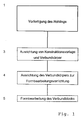
- Fig. 1 shows the process steps in the production of the blank and its subsequent processing for dental reconstruction.
- step 1 the blank is manufactured industrially. It is about in the composite body of the blank To provide an area with optimal chewing properties, an area of great breaking strength and an area made of more resilient, easily workable material. In the finished restoration, material of the reinforcement area will form a reinforcement structure that gives the restoration the necessary mechanical strength.
- the blank can be produced in various ways. Two possible methods are briefly described below.
- a blank is built up in layers from prefabricated, planar layers or laminates made of composite and / or ceramic or glass, carbon or other suitable materials.
- the layers can either be adhesively bonded, for example using composite as an adhesive, or ceramic laminates can also be bonded to one another by composite firing or built up using the coating method.
- Layers made of open-pore ceramic with the same or different pore structure can also be connected to one another with the aid of polymers.
- the polymer is embedded in the pores, on the other hand, it forms a connection between the individual layers.
- the layer thickness is chosen arbitrarily according to the mechanical, stress-related and optical properties and lies between the submicron range (less than 1 micron) and a few millimeters.
- half of the body of the blank thus produced consists of a ceramic and a composite layer, one of the layers forming the reinforcement area.
- layers of composite or ceramic of different construction and composition are formed, the reinforcement being achieved by the special material properties is guaranteed, or the reinforcement of the blank is achieved by the type of layer arrangement, the laminate thickness, the laminate combination, the laminate composite or with combinations of these elements.
- ceramics with different coefficients of thermal expansion are used to produce the blank. The mechanical tension generated thereby strengthens the layers and in particular increases the breaking strength.
- This manufacturing process enables the prefabrication of material layers or material layers, which compared to the monophase production of crown blanks with dimensions of e.g. 12 x 14 x 18 mm made of composite or ceramic allows better quality control.
- the difficulty of producing large material bodies without voids or pores without weak points is avoided with the laminated composite blank.
- a blank is produced in at least two prefabrication steps, namely a first step for prefabricating the reinforcement area from material with high breaking strength and the second step for completing the shape to form the composite body with dental veneering material or Machining material.
- the reinforcement area is prefabricated by casting, slurrying, hot pressing or dry pressing and sintering, extruding or ablation.
- the dimensions of the reinforcement area can be adapted to a typical restoration size.
- densely sintered ceramics made of aluminum oxide, zirconium oxide, magnesium oxide, silicon dioxide or combinations thereof or high-strength polymer material are suitable as reinforcing materials.
- Metal can be used if the reinforcement area does not appear on the surface in the finished reconstruction. In this case titanium is preferred among the metals.
- Shaping of the reinforcement area is supplemented to form the blank body, either without special pretreatment or with preparation of the reinforcement area by applying or forming an adhesion-promoting intermediate layer.
- the inseparable addition to the shape of the reinforcement area with a material of the processing area to form a composite body takes place through heat and pressure polymerization, hot pressing or dry pressing and sintering or firing to a material block adapted to a typical restoration size, which can be machined in all parts. It is also possible to form different areas in parallel, for example by co-extruding different ceramic materials, and with subsequent firing. It is also conceivable to apply ceramic layers using the immersion method or plasma spraying.
- the reinforcement area is preferably arranged in the blank in such a way that its section assigned to the inner portion of the occlusal surface of the restoration with its mesio-distal spatial axis approximately coincides with the central grinding axis of the reconstruction in a subsequent shape grinding process.
- the blank must be equipped with suitable fastening or orientation means that allow it to be clamped in a processing tool in such a way that the position of the reinforcement area is known.
- the orientation means can be connected directly to the reinforcement part or arranged on the finished composite body.
- step 1 of FIG. 1 the finished blank is available.
- the remaining process steps 3-5 according to FIG. 1 can be carried out in dental practice.
- the dentist will first prepare the tooth so that the shape of the desired reconstruction as a design template is established.
- the shape of the composite body is finally carried out using known, ablative devices, in particular by shape grinding.
- the removal of material occurs primarily in the processing area, but in some cases also in the reinforcement area and / or purchase function area.
- the blank is preferably arranged in such a way that the distal reconstruction surface comes to lie on the workpiece holder side, as a result of which it is moved to the reinforcement area that may be apparent on this side to the side of the reconstruction that is not directly visible from the mouth opening.
- the reinforcement material in the inner occlusal area of the reconstruction should at least partially not be less than 0.5 mm thick.
- the reinforcement area 11 is in the form of a flat plate. This plate is connected to a fastener consisting of reference and calibration part 12 and holder part 13.
- the reinforcement area 11 preferably has a shape such that the subsequent material removal from the reinforcement material can be limited to a minimum, which is achieved in FIG. 2 by the plate shape with a wall thickness of approximately 0.5 to 3.0 millimeters.
- the reinforcement area is in the purchase area part (e.g. a crown). It is preferably arranged close to the blank axis 17 but somewhat outside the center.
- the reinforcement region 11 can e.g. B. can also be designed as a substantially U-shaped profile, with a longitudinal axis parallel to the blank axis 17 and an opening angle of the side legs of approximately 10 °.
- the legs 15, 15 'of such a profile are indicated by dashed lines in FIG. 2.
- the u-shape is similar to that of a crown stump preparation and enables additional reinforcement of the sides of the reconstruction, but at the same time a saving of reinforcement material and protection of the tools.
- the reinforcement area can also be curved and / or have the shape of an L-profile.
- the reference and calibration part 12 of the fastening part has a rotationally symmetrical cylindrical design and is closely tolerated. It serves with its cylinder outer surface 18 as a reference and calibration surface that can be approached with the processing tools for calibration.
- the recess 19 ensures that the reinforcement area can only be inserted into the processing device in one position.
- the cylinder outer surface 18 and the recess 19 thus form the orientation means with which the reinforcement region 11 can be brought into a position defined in relation to the machining tool.
- the holder part 13 has an essentially rotationally symmetrical shape which, in the case of a rotary machining, serves as a center of rotation and for fixing the holder part in the processing machine, which is accomplished by means of an adjusting screw or collet.
- the holder part 13 can also be used as a holder e.g. serve in a press mold.
- the holder part 13 or the reference and calibration part 12 and the reinforcement region 11 are directly connected to one another in this embodiment.
- the relative position of the reference and calibration part 12 and the reinforcement area 11 should always be the same for all blanks of one type, so that the position of the reinforcement area can be determined on the basis of the reference surface 18 and the recess 19.
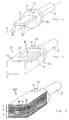
- FIG. 3 shows a first variant of a complete blank 20 with reinforcement area 11 according to FIG. 2. Together, the machining area 9 and the reinforcement area 11 form the body or composite body of the blank that can be formed by ablation.
- the contours 22 seen from the occlusal side of the internal reinforcement region 11 are recorded, and on the side surface 23 the contours viewed from the side 24. These contours serve for orientation about the inner position of the Reinforcement area 11 in the blank 20.
- FIG. 4 A perspective view of a second, currently preferred variant of a complete blank 20 is shown in FIG. 4.
- the blank consists of a variety of flat laminate layers, which, for. B. were assembled by means of composite and / or polymer.
- layers 30 are arranged made of a material which has the highest possible resistance to chewing abrasion, preferably a hard material.
- layers 31 made of a ceramic material with high breaking strength, in a lower region layers 32 of lower hardness and strength, e.g. B. made of composite.
- Composite is easier to machine than ceramics, so that the blank can be optimized with regard to its machinable and manual machinability.
- Area A forms a purchase function area, from which the occlusal surface of the reconstruction is formed, area B forms the reinforcement area, area C the processing area.
- the laminate layers are flat. This is particularly simple in terms of manufacturing technology. However, it is also conceivable for the layers to be curved and, in particular, to be arranged spherically or cylindrically. Such geometries achieve greater strength. Furthermore, the course of the reinforcement area can be better adapted to the respective course of force.
- FIG. 5 illustrates the orientation of a blank for processing.
- a blank according to FIG. 2 with the U-shaped reinforcement area indicated by dashed lines is shown - however, a corresponding alignment also applies to a blank with a flat reinforcement area (such as in the blank according to FIG. 4), in which case the lateral and longitudinal alignment however, is less critical.
- FIG. 5 also shows the arrangement of a three-dimensional oral camera with its shaft 41 and the receiving window 42 to a row of teeth with the teeth 34, 35, 36 and part of the tooth 37.
- a corresponding mouth camera is described, for example, in the above-mentioned document by H. Mörmann and M. Brandestini, The CEREC Computer Reconstruction " , 1989, Quintessenz Verlags-GmbH, Berlin, ISBN 3-87652-550-0, is described.
- the tooth 36 is provided with a crown stump preparation 43.
- the receiving window corresponds to the one in the drawing plane With the help of contours of the reinforcement area 11 as shown in Fig.
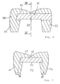
- FIGS. 6 and 7 A finished crown of a molar tooth made from the blank according to FIG. 3 is shown in FIGS. 6 and 7.
- the crown has the shape known to the person skilled in the art with a frustoconical recess 50 for receiving the crown stump of the tooth.
- the blank was ground so that the reinforcement area forms an inner reinforcement plate 52 in the occlusal area, where the greatest loads occur. This plate has a thickness of at least 0.5 mm.
- the legs 15, 15 'form internal reinforcements of the buccal and oral crown walls 55, 56 are used, the legs 15, 15 'form internal reinforcements of the buccal and oral crown walls 55, 56.
- the distal crown wall 53 partially consists of reinforcement material from the area of the reinforcement area on the workpiece holder side, while the mesial wall only through the end of the reinforcement area is reinforced.
- the outside of the mesial, oral, buccal and occlusal crown walls 54, 55, 56, 57 are formed by the processing area of the blank.
- Figures 8 and 9 show a finished crown made of a laminated blank, as shown in Fig. 4, the outlines of the blank 20 and the fastener 12, 13 are indicated by dashed lines.
- the layers 31 of the reinforcement area form a reinforcement plate in the occlusal part of the reconstruction.
- the naturally very hard occlusal tooth surface is formed by the layers 30 of the purchase function area.
- the crown walls were formed from layers 32 of the machining area. Since all laminate layers come to the surface of the crown, they should be made of tooth-colored material.
- the body of the blank consisted of two to three material areas, the reinforcement area, the processing area and possibly the purchase function area.
- the composite body could be formed of two to three material areas, the reinforcement area, the processing area and possibly the purchase function area.
- the individual laminate layers can, for example, become increasingly harder, stronger, more elastic or softer.
- the toughest Laminate layers will preferably be arranged in the upper area of the blank. Under these hardest layers, layers with increasingly greater breaking strength are used, which form the reinforcement area. These then pass into increasingly softer layers in the machining part.
- abrasion-resistant, rigid material e.g. ceramic
- more resilient material e.g. composite
- antagonist-friendly and abrasion-resistant material is arranged in the area of the cusps. In the area of the occlusal plateau, the most break-resistant material possible is used to form the reinforcement area.
- the middle and cervical areas are formed from material that can be machined with little effort.
- the optical and / or X-ray optical properties of the composite body layers can be adapted to the appearance of the natural tooth in terms of translucency or opacity.
Landscapes
- Health & Medical Sciences (AREA)
- Oral & Maxillofacial Surgery (AREA)
- Dentistry (AREA)
- Epidemiology (AREA)
- Life Sciences & Earth Sciences (AREA)
- Animal Behavior & Ethology (AREA)
- General Health & Medical Sciences (AREA)
- Public Health (AREA)
- Veterinary Medicine (AREA)
- Dental Prosthetics (AREA)
Abstract
Description
Die vorliegende Erfindung betrifft einen Rohling bzw. ein Verfahren zur Herstellung künstlicher Zahnteile sowie ein Verfahren zur Herstellung des Rohlings gemäss den Oberbegriffen der unabhängigen Patentansprüche.The present invention relates to a blank or a method for producing artificial tooth parts and a method for producing the blank according to the preambles of the independent claims.
Die Herstellung von dentalen Rekonstruktionen in Form von Kronen und Brücken ist traditionell im zahntechnischen Labor angesiedelt, weil die erforderliche belastungssichere und dauerhafte Festigkeit bisher nur durch den vielstufigen, arbeitsintensiven Aufbau von Verbundkörpern aus belastungstragenden Materialien einerseits und schwächeren Verblendmaterialien andererseits erreicht wurde.The production of dental reconstructions in the form of crowns and bridges has traditionally been carried out in the dental laboratory, because the required load-resistant and permanent strength has so far only been achieved through the multi-stage, labor-intensive construction of composite bodies made of load-bearing materials on the one hand and weaker veneering materials on the other.
Die Herstellung dentaler Rekonstruktionskörper aus Verbundmaterial repräsentiert besonders in Form der Verbund-Metall-Keramischen (VMK) Rekonstruktionen den traditionellen Stand der Technik. Dabei wird auf ein durch Abformung einer Zahnpräparation gewonnenes Arbeitsmodell gusstechnisch eine tragende Unterkonstruktion aus Metall angepasst und dann die Zahnform und -Farbe durch Aufbrennen von Keramikmaterial manuell formgebend ergänzt. Die Kombination des hochfesten Trägermaterials mit dem farbgebenden Verblendmaterial hat sich in der Zahnmedizin als dauerhafte Rekonstruktionsmethode bewährt.The production of dental reconstruction bodies from composite material represents the traditional state of the art, particularly in the form of composite metal-ceramic (VMK) reconstructions. In this process, a supporting substructure made of metal is adapted to a working model obtained by molding a tooth preparation and then the tooth shape and color are manually supplemented by firing ceramic material. The combination of the high-strength backing material with the coloring veneering material has proven itself in dentistry as a permanent reconstruction method.
In einem anderen Verfahrensweg werden für Einzelzahnkronen zur Gewinnung der erforderlichen Kaukraftstabilität zunächst Unterkonstruktionen aus heissgepresster Glaskeramik (IPS-Empress) gefertigt, die den Zahnstumpf in Form von ca. 0.5 mm dicken Kappen oder Hütchen überdecken, und auf diese brennt der Zahntechniker die zur Form- und Farbergänzung nötige Verblendkeramik auf.In a different process, substructures are first made of hot-pressed glass ceramic (IPS-Empress) for individual tooth crowns to obtain the necessary chewing stability, which cover the tooth stump in the form of approx. 0.5 mm thick caps or cones, and the dental technician burns the veneering ceramics.
In neuerer Zeit wurden manuell- (Celay) und computergesteuerte Methoden (Cerec u.a.) bekannt, mit denen dentale Rekonstruktionen und Rekonstruktionsteile aus einphasigen Porzellan- und Keramikmaterialien oder auch Kunststoff- bzw. Kompositmaterialien in Form von Rohlingsblöcken formschleifend in einem einstufigen Prozess gebrauchsfertig hergestellt werden, siehe z.B. W. H. Mörmann, M. Brandestini, ![]()
![]()
In einer gattungsfremden Methode gemäss EP-A-482 000 werden zur Herstellung ganzer, künstlicher Zähne durch maschinelle Abtragung mit der Hennson/Sopha CAD/CAM-Schleiftechnik farbgeschichtete Kunststoffblöcke vorgeschlagen, deren vorgefertigter Schichtverlauf mit Hilfe von Referenzinformationen selektiv freigelegt werden sollte. Andere Formschleif- bzw. Frästechniken stellen vor allem Metallkappen und Brückenteile für die anschliessende Verblendung mit Keramik her (DCS). Diese Restaurationen werden für die makromechanische Verankerung konstruiert und können dann konventionell mit Phosphatzement eingesetzt werden.In a non-generic method according to EP-A-482 000, color-layered plastic blocks are proposed for the production of whole, artificial teeth by machine removal with the Hennson / Sopha CAD / CAM grinding technique, the prefabricated course of the layer of which should be selectively uncovered using reference information. Other form grinding and milling techniques mainly produce metal caps and bridge parts for the subsequent veneering with ceramics (DCS). These restorations are designed for macromechanical anchoring and can then be used conventionally with phosphate cement.
In einem anderen Verfahrensweg werden Alumina Rohlingsblöcke aus porös gesinterter Aluminiumoxidkeramik oder auch porös gesinterte Blöcke aus Spinell nach der Cerec- oder Celay-Formschleiftechnik bearbeitet. Die entstehenden Formteile mit offenporiger Struktur werden nachträglich auf dem zahntechnischen Wege mit Glas (Lanthangläser) heiss-infiltriert (In-Ceramtechnik), wodurch kronen- und brückentaugliche Festigkeitswerte entstehen.In another process, alumina ingots made of porous sintered aluminum oxide ceramics or porous sintered ingots made of spinel are processed using the Cerec or Celay form grinding technique. The resulting molded parts with an open-pore structure are subsequently hot-infiltrated using the dental technique with glass (lanthanum glasses) (In-Ceram technique), resulting in strength values suitable for crowns and bridges.
Im weiteren kann hochfeste, dicht gesinterte Oxidkeramik (Zirkon, Alumina) im zahntechnischen Labor mit der Sonoerosionstechnik zu grazilen Restaurationskörpern verarbeitet werden, auf die dann noch labortechnisch farbgebende Schichten aufgebrannt werden. Die bisher erwähnten, bekannten Verfahren zur Herstellung künstlicher Zahnteile benötigen also mehrere Schritte, um gebrauchsfertige Kronen- und Brückenteile, d.h. extrakoronale Restaurationen bereitzustellen, da diese aus mindestens zwei verbundenen Materialien bestehen, von denen eines die Bruchfestigkeit und ein anderes, schwächeres die naturähnliche Zahnfarbe gewährleistet.In addition, high-strength, densely sintered oxide ceramics (zircon, alumina) can be processed in the dental laboratory using sono-erosion technology to form delicate restoration bodies, onto which layers that give color in the laboratory are then fired. The previously mentioned known methods for producing artificial tooth parts therefore require several steps in order to produce ready-to-use crown and bridge parts, i.e. Provide extracoronal restorations, since they consist of at least two bonded materials, one of which ensures the breaking strength and another, weaker the natural tooth color.
Zweck der vorliegenden Erfindung ist die Vereinfachung der Herstellung gebrauchsfertiger Kronen- und Brückenteile und anderer partieller Zahnrekonstruktionen mit möglichst guten mechanischen Eigenschaften.The purpose of the present invention is to simplify the manufacture of ready-to-use crown and bridge parts and other partial tooth reconstructions with the best possible mechanical properties.
Diese Aufgabe wird durch die Gegenstände der unabhängigen Ansprüche gelöst.This object is solved by the subject matter of the independent claims.
Da der anspruchsgemässe Rohling bereits Bereiche unterschiedlicher Bruchfestigkeit besitzt, kann das gebrauchsfertige Endprodukt in einem einzigen, maschinellen Formprozess geformt werden. Im so hergestellten künstlichen Zahnteil gewährt der Verstärkungsbereich die nötige mechanische Festigkeit, während der Bearbeitungsbereich aus einem Material bestehen kann, das einfach bearbeitbar ist bzw. dessen Eigenschaften (z. B. Elastizität, Struktur, Farbe) den jeweiligen Anforderungen anpassbar sind.Since the blank according to the requirements already has areas of different breaking strength, the ready-to-use end product can be molded in a single, mechanical molding process. In the artificial tooth part produced in this way, the reinforcement area provides the necessary mechanical strength, while the processing area can consist of a material that is easy to process or whose properties (e.g. elasticity, structure, color) can be adapted to the respective requirements.
Dabei sollte der Verstärkungsbereich in möglichst vordefinierter räumlicher Relation zu den Befestigungsmitteln des Rohlings stehen. Damit ist die Position des Verstärkungsbereichs im Bearbeitungswerkzeug bekannt und es wird möglich, beim Formschleifen der dentalen Rekonstruktion sicherzustellen, dass der Verstärkungsbereich an stark belasteten, okklusalen Teilen der Rekonstruktion eine Mindestdicke aufweist. Insbesondere sollte der Verstärkungsbereich bei einer Zahnkrone okklusal vorzugsweise eine Dicke von 0.5 mm nicht unterschreiten.The reinforcement area should be in a predefined spatial relation to the fastening means of the blank. The position of the reinforcement area in the machining tool is thus known and it is possible, when grinding the dental reconstruction, to ensure that the reinforcement area has a minimum thickness on heavily loaded, occlusal parts of the reconstruction. In particular, should the reinforcement area of a tooth crown should preferably not be less than 0.5 mm occlusally.
Vorzugsweise bildet der Verstärkungsbereich eine im wesentlichen ebene Platte. Es zeigt sich, dass ein so geformter, einfach herstellbarer Verstärkungsbereich eine ausreichende Verstärkung gewährleistet. In einer besonders bevorzugten Ausführung umfasst der Körper mehrere Laminatschichten, welche vorzugsweise eben sind. Dadurch wird die Herstellung des Rohlings weiter vereinfacht. Es sind jedoch auch gekrümmte, z.B. zylindrische oder sphärische, Schichtungen denkbar.The reinforcement area preferably forms a substantially flat plate. It can be seen that a reinforcement area shaped in this way and easy to produce ensures sufficient reinforcement. In a particularly preferred embodiment, the body comprises a plurality of laminate layers, which are preferably flat. This further simplifies the manufacture of the blank. However, they are also curved, e.g. cylindrical or spherical, stratifications conceivable.
Der Verstärkungsbereich wird am besten zwischen einem Kaufunktionsbereich und dem Bearbeitungsbereich angeordnet. Der Kaufunktionsbereich weist eine hohe Beständigkeit gegenüber der Kauabrasion auf, und der Verstärkungsbereich erlaubt eine optimale Verteilung der Kaukräfte, während der übrige Bearbeitungsbereich im wesentlichen zur Herstellung des Formschlusses mit der restlichen Zahnhartsubstanz und zur Formergänzung des Zahnes dient. Auf diese Weise kann eine Rekonstruktion hergestellt werden, die okklusal dank dem Kaufunktionsbereich und dem Verstärkungsbereich eine den biologischen Verhältnissen angepasste Kauabrasionsbeständigkeit und Bruchfestigkeit aufweist, während die übrigen Bereiche z.B. auf gute Bearbeitbarkeit optimiert werden können.The reinforcement area is best located between a purchase function area and the processing area. The purchase function area has a high resistance to chewing abrasion, and the reinforcement area allows an optimal distribution of the chewing forces, while the rest of the processing area essentially serves to establish the positive connection with the remaining hard tooth substance and to complete the shape of the tooth. In this way, a reconstruction can be produced which, thanks to the purchase function area and the reinforcement area, has a chewing abrasion resistance and fracture resistance adapted to the biological conditions, while the other areas e.g. can be optimized for good workability.
Der Körper des Rohlings sollte vorzugsweise aus Keramik, Kompositmaterial, Gläsern und/oder hochfesten Polymermaterialien bestehen. Diese Werkstoffe können zahnfarben hergestellt werden, so dass sich die einzelnen Bereiche bis an die Oberfläche der dentalen Rekonstruktion erstrecken können.The body of the blank should preferably consist of ceramic, composite material, glasses and / or high-strength polymer materials. These materials can be made tooth-colored so that the individual areas can extend to the surface of the dental reconstruction.
Der erfindungsgemässe Rohling eignet sich insbesondere für die Herstellung von Inlays, Overlays, teilweisen und vollständigen Kronen und Brücken, d. h. Teilen eines Zahnes oder ganzer Zähne. Obwohl diese Teile unter Umständen sehr dünn bzw. fein sind, können mittels geeigneter Positionierung und Verarbeitung des Verstärkungsbereichs die nötige Festigkeit und die gewünschten elastischen Eigenschaften der Rekonstruktion gewährleistet werden.The blank according to the invention is particularly suitable for the production of inlays, overlays, partial and complete crowns and bridges, ie parts of a tooth or entire teeth. Although these parts may be very thin or fine, the reinforcement area can be positioned and processed appropriately the necessary strength and the desired elastic properties of the reconstruction can be guaranteed.
Weitere Vorteile und Anwendungen der Erfindung ergeben sich aus der nun folgenden Beschreibung einiger Ausführungsbeispiele anhand der beiliegenden Figuren.
Darin zeigen:
- Fig. 1 ein Flussdiagramm der Herstellung des Rohlings und dessen Bearbeitung,
- Fig. 2 eine erste Variante des Tragteils in perspektivischer Darstellung,
- Fig. 3 eine erste Variante eines vollständigen Verbundkörpers mit der ersten Variante des Tragteils gemäss Fig. 2 in perspektivischer Darstellung,
- Fig. 4 eine zweite Variante eines vollständigen Rohlings,
- Fig. 5 die mesiale und distale Anordnung des Rohlings bei einer Kronenstumpfpräparation,
- Fig. 6 einen schematischen mesio-distalen Vertikalschnitt durch eine Krone hergestellt aus dem Verbundkörper von Fig. 3,
- Fig. 7 einen Schnitt entlang Linie VII-VII von Fig. 6,
- Fig. 8 einen schematischen mesio-distalen Vertikalschnitt durch eine Krone hergestellt aus einem laminierten Verbundkörper, und
- Fig. 9 einen Schnitt entlang Linie IX-IX von Fig. 8.
In it show:
- 1 is a flow chart of the production of the blank and its processing,
- 2 shows a first variant of the support part in a perspective view,
- 3 shows a first variant of a complete composite body with the first variant of the supporting part according to FIG. 2 in a perspective view,
- 4 shows a second variant of a complete blank,
- 5 shows the mesial and distal arrangement of the blank in a crown stump preparation,
- 6 shows a schematic mesio-distal vertical section through a crown made from the composite body from FIG. 3,
- 7 shows a section along line VII-VII of FIG. 6,
- Fig. 8 is a schematic mesio-distal vertical section through a crown made of a laminated composite body, and
- 9 shows a section along line IX-IX of FIG. 8.
Im folgenden werden nun kurz die Schritte zur Herstellung des erfindungsgemässen Rohlings und zu dessen Verarbeitung beschrieben. Sodann werden einige konkrete Ausführungen des Rohlings diskutiert.The steps for producing and processing the blank according to the invention are now briefly described below. Then some concrete explanations of the blank are discussed.
Fig. 1 zeigt die Verfahrensschritte bei der Herstellung des Rohlings und dessen nachfolgender Verarbeitung zur dentalen Rekonstruktion.Fig. 1 shows the process steps in the production of the blank and its subsequent processing for dental reconstruction.
In Schritt 1 wird der Rohling industriell hergestellt. Dabei geht es darum, im Verbundkörper des Rohlings einen Bereich mit optimalen Kaueigenschaften, einen Bereich grosser Bruchfestigkeit und einen Bereich aus resilienterem, gut bearbeitbarem Material bereitzustellen. In der fertigen Restauration wird Material des Verstärkungsbereichs eine Verstärkungsstruktur bilden, die der Restauration die nötige mechanische Bruchfestigkeit verleiht.In
Die Herstellung des Rohlings kann auf verschiedene Weise geschehen. Im folgenden werden zwei Mögliche Verfahren kurz beschrieben.The blank can be produced in various ways. Two possible methods are briefly described below.
In einem ersten, bevorzugten Herstellungsprozess wird ein Rohling, wie er z.B. in Fig. 4 gezeigt ist, schichtweise aus vorgefertigten, planaren Lagen bzw. Laminaten aus Komposit und/oder Keramik bzw. Glas, Kohlenstoff oder anderen geeigneten Materialien aufgebaut. Die Schichten können dabei entweder adhäsiv, z.B. unter Verwendung von Komposit als Klebstoff, verbunden werden, oder Keramiklaminate können auch durch Verbundbrand miteinander verbunden bzw. mittels Coatingverfahren aufgebaut werden. Auch können Lagen aus offenporiger Keramik mit gleicher oder unterschiedlicher Porenstruktur mit Hilfe von Polymeren miteinander verbunden werden. Dabei wird das Polymer einerseits in die Poren eingelagert, andererseits bildet es eine Verbindung zwischen den einzelnen Lagen. (Zur Technik der offenporigen, polymerbehandelten Keramiken wird verwiesen auf Marks et al., J.Dent.Res. 75:148 Abstr. No 1041, 1996.) Die Schichtdicke wird dabei beliebig nach den mechanischen, belastungstechnischen und optischen Eigenschaften gewählt und liegt zwischen dem Submikronbereich (kleiner als 1 Mikrometer) und einigen Millimetern. In seiner einfachsten Form besteht der so hergestellte Körper des Rohlings zur Hälfte aus einer Keramik- und einer Kompositschicht, wobei eine der Schichten den Verstärkungsbereich bildet. Es ist aber auch denkbar, dass Schichten von Komposit bzw. Keramik unterschiedlicher Konstruktion und Zusammensetzung gebildet werden, wobei die Verstärkung durch die speziellen Materialeigenschaften gewährleistet wird, oder aber die Verstärkung des Rohlings durch die Art der Schichtungsanordnung, der Laminatdicke, der Laminatkombination, des Laminatverbundes oder mit Kombinationen dieser Elemente erreicht wird. Es ist auch denkbar, dass Keramiken mit unterschiedlichen Wärmeausdehnungskoeffizienten zur Herstellung des Rohlings verwendet werden. Die dadurch erzeugte mechanische Verspannung verstärkt die Schichten und erhöht insbesondere die Bruchfestigkeit.In a first, preferred manufacturing process, a blank, as shown, for example, in FIG. 4, is built up in layers from prefabricated, planar layers or laminates made of composite and / or ceramic or glass, carbon or other suitable materials. The layers can either be adhesively bonded, for example using composite as an adhesive, or ceramic laminates can also be bonded to one another by composite firing or built up using the coating method. Layers made of open-pore ceramic with the same or different pore structure can also be connected to one another with the aid of polymers. On the one hand, the polymer is embedded in the pores, on the other hand, it forms a connection between the individual layers. (For the technique of open-pore, polymer-treated ceramics, reference is made to Marks et al., J.Dent.Res. 75: 148 Abstr. No 1041, 1996.) The layer thickness is chosen arbitrarily according to the mechanical, stress-related and optical properties and lies between the submicron range (less than 1 micron) and a few millimeters. In its simplest form, half of the body of the blank thus produced consists of a ceramic and a composite layer, one of the layers forming the reinforcement area. However, it is also conceivable that layers of composite or ceramic of different construction and composition are formed, the reinforcement being achieved by the special material properties is guaranteed, or the reinforcement of the blank is achieved by the type of layer arrangement, the laminate thickness, the laminate combination, the laminate composite or with combinations of these elements. It is also conceivable that ceramics with different coefficients of thermal expansion are used to produce the blank. The mechanical tension generated thereby strengthens the layers and in particular increases the breaking strength.
Dieses Herstellungsverfahren ermöglicht die Vorfertigung von Materialschichten bzw. Materiallagen, was gegenüber der monophasigen Fertigung von Kronenrohlingen mit Abmessungen von z.B. 12 x 14 x 18 mm aus Komposit oder Keramik eine bessere Qualitätskontrolle erlaubt. Die Schwierigkeit, grosse Materialkörper lunker- bzw. porenfrei ohne Schwachstellen herzustellen, wird beim laminierten Verbundrohling vermieden.This manufacturing process enables the prefabrication of material layers or material layers, which compared to the monophase production of crown blanks with dimensions of e.g. 12 x 14 x 18 mm made of composite or ceramic allows better quality control. The difficulty of producing large material bodies without voids or pores without weak points is avoided with the laminated composite blank.
In einem zweiten möglichen Herstellungsverfahren wird ein Rohling, wie er z.B. in Fig. 3 gezeigt ist, in mindestens zwei Vorfertigungsschritten hergestellt, nämlich einem ersten Schritt zur Vorfertigung des Verstärkungsbereichs aus Material hoher Bruchfestigkeit und dem zweiten Schritt zur Formergänzung zum Verbundkörper mit dentalem Verblendmaterial bzw. Bearbeitungsmaterial. Die Vorfertigung des Verstärkungsbereichs geschieht durch Giessen, Schlickern, Heisspressen oder Trockenpressen und Sintern, Extrudieren oder Abtragung. Der Verstärkungsbereich kann dabei in seinen Dimensionen an eine typische Restaurationsgrösse angepasst werden. Als Verstärkungsmaterial kommt insbesondere dichtgesinterte Keramik aus Aluminiumoxid, Zirkonoxid, Magnesiumoxid, Siliziumdioxid oder Kombinationen hiervon oder hochfestes Polymermaterial in Frage. Metall kann verwendet werden, wenn der Verstärkungsbereich in der fertigen Rekonstruktion nicht an die Oberfläche tritt. In diesem Falle ist Titan unter den Metallen bevorzugt. Nach der Ausformung des Verstärkungsbereichs wird dieser zum Rohlingskörper ergänzt, entweder ohne spezielle Vorbehandlung oder mit einer Vorbereitung des Verstärkungsbereichs durch Auftragen bzw. Bildung einer haftvermittelnden Zwischenschicht. Die untrennbare Formergänzung des Verstärkungsbereichs mit einem Material des Bearbeitungsbereichs zu einem Verbundkörper geschieht durch Hitze- und Druckpolymerisation, Heisspressen oder Trockenpressen und Sintern bzw. Brennvorgang zu einem einer typischen Restaurationsgrösse angepassten Materialblock, der in allen Teilen abtragend bearbeitbar ist. Es ist auch möglich, verschiedene Bereiche parallel zu bilden, beispielsweise durch Co-Extrusion unterschiedlicher Keramikmassen, und mit nachfolgendem Brennen. Im weiteren ist auch das Auftragen von Keramikschichten im Tauchverfahren oder Plasmaspritzen denkbar.In a second possible production method, a blank, as shown, for example, in FIG. 3, is produced in at least two prefabrication steps, namely a first step for prefabricating the reinforcement area from material with high breaking strength and the second step for completing the shape to form the composite body with dental veneering material or Machining material. The reinforcement area is prefabricated by casting, slurrying, hot pressing or dry pressing and sintering, extruding or ablation. The dimensions of the reinforcement area can be adapted to a typical restoration size. In particular, densely sintered ceramics made of aluminum oxide, zirconium oxide, magnesium oxide, silicon dioxide or combinations thereof or high-strength polymer material are suitable as reinforcing materials. Metal can be used if the reinforcement area does not appear on the surface in the finished reconstruction. In this case titanium is preferred among the metals. After Shaping of the reinforcement area is supplemented to form the blank body, either without special pretreatment or with preparation of the reinforcement area by applying or forming an adhesion-promoting intermediate layer. The inseparable addition to the shape of the reinforcement area with a material of the processing area to form a composite body takes place through heat and pressure polymerization, hot pressing or dry pressing and sintering or firing to a material block adapted to a typical restoration size, which can be machined in all parts. It is also possible to form different areas in parallel, for example by co-extruding different ceramic materials, and with subsequent firing. It is also conceivable to apply ceramic layers using the immersion method or plasma spraying.
Unabhängig vom Herstellungsverfahren wird der Verstärkungsbereich vorzugsweise so im Rohling angeordnet, dass sein dem inneren Anteil der Kaufläche der Restauration zugeordneter Abschnitt mit seiner mesio-distalen Raumachse sich bei einem nachfolgenden Formschleifprozess mit der zentralen Schleifachse der Rekonstruktion ungefähr deckt.Regardless of the manufacturing process, the reinforcement area is preferably arranged in the blank in such a way that its section assigned to the inner portion of the occlusal surface of the restoration with its mesio-distal spatial axis approximately coincides with the central grinding axis of the reconstruction in a subsequent shape grinding process.
Der Rohling muss mit geeigneten Befestigungs- bzw. Orientierungsmitteln ausgerüstet sein, die es erlauben, ihn so in ein Bearbeitungswerkzeug einzuspannen, dass die Position des Verstärkungsbereichs bekannt ist. Die Orientierungsmittel können direkt mit dem Verstärkungsteil verbunden oder am fertigen Verbundkörper angeordnet werden.The blank must be equipped with suitable fastening or orientation means that allow it to be clamped in a processing tool in such a way that the position of the reinforcement area is known. The orientation means can be connected directly to the reinforcement part or arranged on the finished composite body.
Mit Abschluss des Schritts 1 von Fig. 1 liegt der fertige Rohling vor. Die übrigen Verfahrensschritte 3 - 5 nach Fig. 1 können in der zahnärztlichen Praxis ausgeführt werden. Hierzu wird der Zahnarzt den Zahn zuerst präparieren, so dass die Form der gewünschten Rekonstruktion als Konstruktionsvorlage feststeht.At the end of
Der dritte Verfahrensschritt 3 besteht nun in der räumlichen Ausrichtung von Konstruktionsvorlage und Verbundkörper zueinander. Hierzu wird die räumliche Kontur des Verstärkungsbereichs im Verbundkörper so ausgerichtet, dass er sich mit der gewünschten Tragstruktur in der Okklusalfläche deckt. Die Raumzuordnung des Verbundkörpers zur räumlichen Schleifvorlage hat so zu geschehen, dass der Verstärkungsbereich beim Schleifen der inneren Passform mindestens teilweise als tragendes Element erhalten bleibt. Der räumliche Rekonstruktionsbezug wird entweder zu einer manuell erzeugten Vor-Rekonstruktion (z.B. Kunststoffkrone) oder zu einem digitalisierten Datensatz (z.B. optisch-dreidimensionale Bilddaten, "optischer Abdruck") hergestellt. Hierzu gibt es verschiedene Möglichkeiten, die einzeln oder zum Teil auch kombiniert verwendet werden können:
- a) Für die ungefähre Ausrichtung, z.B. eines physischen Kronenmodells, können auf den Verbundkörperaussenflächen Markierungslinien angebracht sein, die auf die Innenlage des Verstärkungsbereiches hinweisen und nach denen der Verbundkörper in einer Formschleifmaschine ausgerichtet werden kann;
- b) Bei einer optischen Abdrucknahme wird die Kamera entsprechend der zentralen, mesio-distalen Zahnreihenachse ausgerichtet. Der so ermittelte Datensatz legt die Schleifachse in der Zahnreihenachse fest. Es können auch die innenliegenden Konturen des Verstärkungsbereichs mit der Aussenkontur des zu verwendenden Rohlings als Overlay in ein Monitorbild eingeblendet werden und die Kamera wird vom Benutzer bei der Aufnahme so gehalten, dass der tragende Verbundblockteil die individuelle Präparation mindestens in der Horizontalebene bestimmungsgemäss überlagert;
- c) Die räumliche Zuordnung von optisch-dreidimensionalen Bilddaten zum Verbundkörper wird automatisch durch Bildüberlagerung rechnergestützt durchgeführt, wobei die räumlichen Daten der Präparationsoberflächen den Oberflächendaten der im passenden Verbundkörper zur Verfügung stehenden inneren tragenden Anteile durch Anwendung eines geeigneten Ueberlagerungs-('Matching-') Algorithmus in allen Raumkoordinaten bestimmungsgemäss angepasst werden.
- a) For the approximate alignment, for example of a physical crown model, marking lines can be applied to the outer surfaces of the composite body, which indicate the inner layer of the reinforcement area and according to which the composite body can be aligned in a form grinding machine;
- b) When taking an optical impression, the camera is aligned according to the central, mesio-distal axis of the tooth row. The data record determined in this way defines the grinding axis in the tooth row axis. The inner contours of the reinforcement area with the outer contour of the blank to be used can also be overlaid in a monitor image and the camera is held by the user when the picture is taken so that the load-bearing composite block part overlays the individual preparation as intended, at least in the horizontal plane;
- c) The spatial assignment of optical three-dimensional image data to the composite body is carried out automatically by means of image superimposition, with the spatial data of the preparation surfaces the surface data of the internal load-bearing components available in the matching composite body are adapted in accordance with the intended purpose in all spatial coordinates by using a suitable matching algorithm.
Der vierte Verfahrensschritt 4 besteht in der räumlichen Ausrichtung des Verbundkörpers bzw. des Verstärkungsbereichs zur Formbearbeitungsvorrichtung. Hierbei wird die Raumlage des Verstärkungsbereichs relativ zum Bearbeitungswerkzeug festgelegt. Dabei kann zum Beispiel die Längsachse des Verstärkungsbereichs mit der Rotationsachse eines Bearbeitungswerkzeugs in Deckung gebracht und die Winkelposition durch einen Anschlag am Halter festgelegt werden. Zu diesem Zweck sind am Befestigungsmittel des Rohlings Orientierungshilfen vorgesehen, die es erlauben, die nötige Raumrelation zwischen Bearbeitungswerkzeug und Verstärkungsbereich herzustellen. Die Orientierungshilfen können in verschiedenster Art bereitgestellt werden, z.B. als:
- a) eine kontinuierliche Verlängerung des Verstärkungsbereichs und mit einer Ausbildung als Werkstückhalter mit Referenzflächen ausserhalb des Verbundkörpers;
- b) ein separat geformter Werkstückhalter, der mit dem Verstärkungsbereich formschlüssig verbunden ist; oder
- c) ein separat gefertigter Werkstückhalter, der mit dem Verbundkörper formschlüssig verbunden ist, wobei die relative Lage des Werkstückhalters zum Verstärkungsbereich bekannt ist, z.B. indem die Längsrotationsachse des Verstärkungsbereichs mit der Längsrotationsachse des tragenden Teils zusammenfällt.
- a) a continuous extension of the reinforcement area and with a training as a workpiece holder with reference surfaces outside the composite body;
- b) a separately shaped workpiece holder, which is positively connected to the reinforcement area; or
- c) a separately manufactured workpiece holder which is positively connected to the composite body, the relative position of the workpiece holder to the reinforcement region being known, for example by the longitudinal axis of rotation of the reinforcement region coinciding with the longitudinal axis of rotation of the supporting part.
Im fünften Verfahrensschritt 5 erfolgt schliesslich die Formbearbeitung des Verbundkörpers mit bekannten, abtragend arbeitenden Vorrichtungen, insbesondere durch Formschleifen. Die Materialabtragung geschieht in erster Linie im Bearbeitungsbereich, zum Teil aber auch im Verstärkungsbereich und/oder Kaufunktionsbereich. Dabei wird der Rohling vorzugsweise so angeordnet, dass die distale Rekonstruktionsfläche werkstückhalterseitig zu liegen kommt, wodurch er eventuell auf dieser Seite zutage tretende Verstärkungsbereich auf die von der Mundöffnung her nicht direkt einsehbare Seite der Rekonstruktion verlegt wird. Das Verstärkungsmaterial im inneren okklusalen Bereich der Rekonstruktion sollte mindestens teilweise die Stärke von 0,5 mm nicht unterschreiten.In the
In Fig. 2 ist eine erste Variante des Rohlings abgebildet, wobei der Bearbeitungsbereich nicht dargestellt ist. In dieser Ausführung hat der Verstärkungsbereich 11 die Form einer ebenen Platte. Diese Platte ist mit einem Befestigungsmittel bestehend aus Referenz- und Kalibrierungsteil 12 und Halterteil 13 verbunden.2 shows a first variant of the blank, the machining area not being shown. In this embodiment, the
Der Verstärkungsbereich 11 weist vorzugsweise eine derartige Formgebung auf, dass die nachfolgende Materialabtragung am Verstärkungsmaterial auf ein Minimum beschränkt werden kann, was in Fig. 2 durch die Plattenform mit einer Wandstärke von ca. 0.5 bis 3.0 Millimetern erreicht wird. In der fertigen Rekonstruktion liegt der Verstärkungsbereich im Kauflächenteil (z.B. einer Krone). Er wird vorzugsweise nahe bei der Rohlingsachse 17 aber etwas ausserhalb der Mitte angeordnet.The
Der Verstärkungsbereich 11 kann z. B. auch als im wesentlichen u-förmiges Profil ausgestaltet sein, mit Längsachse parallel zur Rohlingsachse 17 und einem Oeffnungswinkel der Seitenschenkel von ca. 10°. Die Schenkel 15, 15' eines solchen Profils sind in Fig. 2 gestrichelt angedeutet. Die u-Form ist der einer Kronenstumpfpräparation ähnlich und ermöglicht eine zusätzliche Verstärkung der Seiten der Rekonstruktion, aber gleichzeitig eine Einsparung von Verstärkungsmaterial und eine Schonung der Werkzeuge. Der Verstärkungsbereich kann auch gebogen sein und/oder die Form eines L-Profils besitzen.The
Der Referenz- und Kalibrierungsteil 12 des Befestigungsteils ist rotationssymmetrisch zylindrisch gestaltet und eng toleriert. Er dient mit seiner Zylinderaussenfläche 18 als Referenz- und Eichfläche, die mit den Bearbeitungswerkzeugen zur Kalibrierung angefahren werden kann. Die Ausnehmung 19 stellt sicher, dass der Verstärkungsbereich nur in einer Position in die Bearbeitungsvorrichtung eingesetzt werden kann. Somit bilden die Zylinderaussenfläche 18 und die Ausnehmung 19 die Orientierungsmittel, mit denen der Verstärkungsbereich 11 in eine zum Bearbeitungswerkzeug definierte Lage gebracht werden kann.The reference and
Der Halterteil 13 weist eine im wesentlichen rotationssymmetrische Form auf, die bei einer rotativen Bearbeitung als Rotationszentrum und zur Festlegung des Halterteils in der Bearbeitungsmaschine dient, was mittels Stellschraube oder Spannzange bewerkstelligt wird. Der Halterteil 13 kann bei der Herstellung des vollständigen Verbundkörpers durch Formergänzung zum Verbundblock ebenfalls als Halter z.B. in einer Pressform dienen.The
Der Halterteil 13 bzw. der Referenz- und Kalibrierungsteil 12 und der Verstärkungsbereich 11 sind in dieser Ausführung direkt miteinander verbunden. Die relative Lage von Referenz- und Kalibrierungsteil 12 und Verstärkungsbereich 11 sollte bei allen Rohlingen eines Typs möglichst immer gleich sein, so dass sich die Position des Verstärkungsbereichs aufgrund der Referenzfläche 18 und der Ausnehmung 19 bestimmen lässt.The
In Fig. 3 ist eine erste Variante eines vollständigen Rohlings 20 mit Verstärkungsbereich 11 gemäss Fig. 2. Zusammen bilden der Bearbeitungsbereich 9 und der Verstärkungsbereich 11 den durch Abtragung formbaren Körper bzw. Verbundkörper des Rohlings.FIG. 3 shows a first variant of a complete blank 20 with
Auf der okklusal zugeordneten Verbundkörperoberfläche 21, die gleich orientiert ist wie die Ausnehmung 19, sind die von okklusal gesehenen Konturen 22 des innenliegenden Verstärkungsbereiches 11 aufgezeichnet, und auf der Seitenfläche 23 die von seitlich gesehenen Konturen 24. Diese Konturen dienen der Orientierung über die Innenlage des Verstärkungsbereiches 11 im Rohling 20.On the occlusally assigned
In Fig. 4 ist eine zweite, zur Zeit bevorzugte Variante eines vollständigen Rohlings 20 perspektivisch dargestellt. Hier besteht der Rohling aus einer Vielzahl von ebenen Laminatschichten, die z. B. mittels Komposit und/oder Polymer zusammengefügt wurden. In einem obersten Bereich A sind Schichten 30 aus einem Material angeordnet, welches möglichst hohe Beständigkeit gegen Kauabrasion besitzt, vorzugsweise ein hartes Material. In einem mittleren Bereich B liegen Schichten 31 aus einem Keramikmaterial mit hoher Bruchfestigkeit, in einem unteren Bereich Schichten 32 geringerer Härte und Festigkeit, z. B. aus Komposit. Komposit ist leichter maschinell bearbeitbar als Keramik, so dass der Rohling durch Kompositanteile bezüglich seiner maschinellen und manuellen Bearbeitbarkeit optimiert werden kann.A perspective view of a second, currently preferred variant of a complete blank 20 is shown in FIG. 4. Here, the blank consists of a variety of flat laminate layers, which, for. B. were assembled by means of composite and / or polymer. In an uppermost region A, layers 30 are arranged made of a material which has the highest possible resistance to chewing abrasion, preferably a hard material. In a central region B there are
Der Bereich A bildet einen Kaufunktionsbereich, aus welchem die okklusale Oberfläche der Rekonstruktion gebildet wird, der Bereich B bildet den Verstärkungsbereich, der Bereich C den Bearbeitungsbereich.Area A forms a purchase function area, from which the occlusal surface of the reconstruction is formed, area B forms the reinforcement area, area C the processing area.
Im Rohling nach Fig. 4 sind die Laminatschichten eben ausgeführt. Dies ist herstellungstechnisch besonders einfach. Es ist jedoch auch denkbar, dass die Schichten gekrümmt sind und insbesondere sphärisch oder zylindrisch angeordnet sind. Durch solche Geometrien wird eine grössere Festigkeit erreicht. Ferner kann der Verlauf des Verstärkungsbereichs besser dem jeweiligen Kraftverlauf angepasst werden.4, the laminate layers are flat. This is particularly simple in terms of manufacturing technology. However, it is also conceivable for the layers to be curved and, in particular, to be arranged spherically or cylindrically. Such geometries achieve greater strength. Furthermore, the course of the reinforcement area can be better adapted to the respective course of force.
Fig. 5 illustriert die Orientierung eines Rohlings zur Bearbeitung. Hierbei wird ein Rohling gemäss Fig. 2 mit dem gestrichelt angedeuteten u-förmigen Verstärkungsbereich gezeigt - eine entsprechende Ausrichtung gilt jedoch auch für einen Rohling mit ebenem Verstärkungsbereich (wie z.B. im Rohling nach Fig. 4), wobei in diesem Falle die laterale und longitudinale Ausrichtung jedoch weniger kritisch ist.5 illustrates the orientation of a blank for processing. A blank according to FIG. 2 with the U-shaped reinforcement area indicated by dashed lines is shown - however, a corresponding alignment also applies to a blank with a flat reinforcement area (such as in the blank according to FIG. 4), in which case the lateral and longitudinal alignment however, is less critical.
Fig. 5 zeigt auch die Anordnung einer dreidimensional messenden Mundkamera mit ihrem Schaft 41 und dem Aufnahmefenster 42 zu einer Zahnreihe mit den Zähnen 34, 35, 36 und einem Teil des Zahnes 37. Eine entsprechende Mundkamera ist z.B. in der bereits erwähnten Schrift von H. Mörmann und M. Brandestini, ![]()
![]()
Eine fertige Krone eines Backenzahns hergestellt aus dem Rohling nach Figur 3 wird in den Figuren 6 und 7 gezeigt. Die Krone weist die dem Fachmann bekannte Formgebung mit einer kegelstumpfförmigen Aussparung 50 zur Aufnahme des Kronenstumpfs des Zahns auf. Der Rohling wurde so formgeschliffen, dass der Verstärkungsbereich eine innen liegende Verstärkungsplatte 52 im okklusalen Bereich bildet, wo die grössten Belastungen auftreten. Diese Platte weist eine Dicke von mindestens 0.5 mm auf.A finished crown of a molar tooth made from the blank according to FIG. 3 is shown in FIGS. 6 and 7. The crown has the shape known to the person skilled in the art with a
Wird die in Fig. 2 gestrichelt gezeichnete u-Form des Verstärkungsbereichs verwendet, so bilden die Schenkel 15, 15' innenliegenden Verstärkungen der bukkalen und oralen Kronenwände 55, 56. Die distale Kronenwand 53 besteht teilweise aus Verstärkungsmaterial vom werkstückhalterseitigen Bereich des Verstärkungsbereichs, während die mesiale Wand nur durch das Ende des Verstärkungsbereichs verstärkt wird. Die Aussenseiten der mesialen, oralen, bukkalen und okklusalen Kronenwände 54, 55, 56, 57 werden vom Bearbeitungsbereich des Rohlings gebildet.If the u-shape of the reinforcement area shown in dashed lines in FIG. 2 is used, the
Die Figuren 8 und 9 zeigen eine fertige Krone hergestellt aus einem laminierten Rohling, wie er in Fig. 4 dargestellt ist, wobei die Umrisse des Rohlings 20 und des Befestigungsmittels 12, 13 gestrichelt angedeutet sind. In diesem Falle bilden die Schichten 31 des Verstärkungsbereichs eine Verstärkungsplatte im okklusalen Teil der Rekonstruktion. Die natürlicherweise sehr harte okklusale Zahnoberfläche wird von den Schichten 30 des Kaufunktionsbereichs gebildet. Die Kronenwände wurden aus den Schichten 32 des Bearbeitungsbereichs geformt. Da alle Laminatschichten bis an die Oberfläche der Krone treten, sollten sie aus zahnfarbenem Material bestehen.Figures 8 and 9 show a finished crown made of a laminated blank, as shown in Fig. 4, the outlines of the blank 20 and the
Wie aus den Figuren 6 - 9 ersichtlich ist, muss zur Herstellung der Krone vor allem Material des Bearbeitungsbereichs und nur wenig Material des Verstärkungs- bzw. Kaufunktionsbereichs abgetragen werden. Da der Kaufunktionsbereich aus der Mitte des Rohlings etwas versetzt ist, muss auch im Bereich der Aussparung 50 nur wenig des harten Verstärkungsmaterials entfernt werden. Dadurch braucht das Formschleifen weniger Zeit und die Bearbeitungswerkzeuge werden geschont.As can be seen from FIGS. 6-9, in order to produce the crown, above all material of the processing area and only a little material of the reinforcement or purchasing function area must be removed. Since the purchase function area is somewhat offset from the center of the blank, only a little of the hard reinforcing material has to be removed in the area of the
In den soweit gezeigten Ausführungsbeispielen bestand der Körper des Rohlings aus zwei bis drei Materialbereichen, dem Verstärkungsbereich, dem Bearbeitungsbereich und ggf. dem Kaufunktionsbereich. Es ist aber auch möglich, dass mehr als nur zwei bzw. drei Komponenten den Verbundkörper bilden. Es ist denkbar, dass anstelle klar definierter Phasengrenzen zwischen den Komponenten des Verbundkörpers kontinuierliche oder fein abgestufte Materialübergänge bzw. Materialgradienten gebildet werden. In der laminierten Ausführung nach Fig. 4, können die einzelnen Laminatschichten z.B. zunehmend härter, fester, elastischer oder weicher werden. Die härtesten Laminatschichten werden vorzugsweise im oberen Bereich des Rohlings angeordnet werden. Unter diesen härtesten Schichten kommen Schichten mit zunehmend grösserer Bruchfestigkeit zum Einsatz, welche den Verstärkungsbereich bilden. Diese gehen dann in zunehmend weichere Schichten des Bearbeitungsteils über. Es kann also, dem natürlichen Vorbild folgend, von den Höckerspitzen bis zum Zahnhals ein kontinuierlicher Übergang von abrasionsresistentem, rigidem Material (z.B. Keramik) zu resilienterem Material (z.B. Komposit) erfolgen, wodurch die übertragung und Verteilung der Kaukräfte auf den natürlichen Restzahn ausgeglichener wird. Beispielsweise wird im Bereich der Höcker antagonistenfreundliches und abrasionsresistentes Material angeordnet. Im Bereich des okklusalen Plateaus kommt möglichst bruchfestes Material zur Bildung des Verstärkungsbereichs zum Einsatz. Die mittleren und zervikalen Bereiche werden aus mit geringem Aufwand bearbeitbarem Material gebildet. Die optischen und/oder röntgenoptischen Eigenschaften der Verbundkörperschichten können bezüglich der Transluzenz bzw. Opazität dem Erscheinungsbild des natürlichen Zahnes angepasst werden.In the exemplary embodiments shown so far, the body of the blank consisted of two to three material areas, the reinforcement area, the processing area and possibly the purchase function area. However, it is also possible for more than just two or three components to form the composite body. It is conceivable that instead of clearly defined phase boundaries between the components of the composite body, continuous or finely graduated material transitions or material gradients are formed. In the laminated embodiment according to FIG. 4, the individual laminate layers can, for example, become increasingly harder, stronger, more elastic or softer. The toughest Laminate layers will preferably be arranged in the upper area of the blank. Under these hardest layers, layers with increasingly greater breaking strength are used, which form the reinforcement area. These then pass into increasingly softer layers in the machining part. According to the natural model, there can be a continuous transition from abrasion-resistant, rigid material (e.g. ceramic) to more resilient material (e.g. composite) from the cusp tips to the neck of the tooth, whereby the transfer and distribution of the chewing forces on the natural residual tooth is more even. For example, antagonist-friendly and abrasion-resistant material is arranged in the area of the cusps. In the area of the occlusal plateau, the most break-resistant material possible is used to form the reinforcement area. The middle and cervical areas are formed from material that can be machined with little effort. The optical and / or X-ray optical properties of the composite body layers can be adapted to the appearance of the natural tooth in terms of translucency or opacity.
Claims (19)
Applications Claiming Priority (3)
| Application Number | Priority Date | Filing Date | Title |
|---|---|---|---|
| CH125196 | 1996-05-17 | ||
| CH125196 | 1996-05-17 | ||
| CH1251/96 | 1996-05-17 |
Publications (2)
| Publication Number | Publication Date |
|---|---|
| EP0807422A1 true EP0807422A1 (en) | 1997-11-19 |
| EP0807422B1 EP0807422B1 (en) | 2004-11-03 |
Family
ID=4206029
Family Applications (1)
| Application Number | Title | Priority Date | Filing Date |
|---|---|---|---|
| EP97106979A Expired - Lifetime EP0807422B1 (en) | 1996-05-17 | 1997-04-27 | Method for manufacturing dental reconstructions and blank for carrying out the method |
Country Status (5)
| Country | Link |
|---|---|
| US (1) | US5939211A (en) |
| EP (1) | EP0807422B1 (en) |
| JP (1) | JPH1094551A (en) |
| AT (1) | ATE281126T1 (en) |
| DE (1) | DE59712052D1 (en) |
Cited By (12)
| Publication number | Priority date | Publication date | Assignee | Title |
|---|---|---|---|---|
| JP2000070289A (en) * | 1998-08-28 | 2000-03-07 | Espe Dental Ag | Apparatus for manufacturing dental restoration parts |
| DE19944130A1 (en) * | 1999-09-15 | 2001-04-12 | Paul Weigl | Automatic manufacturing method for dental prosthesis uses machining of standard material block with regions having different optical characteristics via virtual positioning of prosthesis within block |
| WO2002045614A1 (en) * | 2000-12-07 | 2002-06-13 | Eidgenössische Technische Hochschule Zürich Nichtmetallische Werkstoffe | Holding device for a ceramic blank |
| DE202006006286U1 (en) * | 2006-04-19 | 2007-08-30 | Merz Dental Gmbh | Machinable blank for dentures |
| WO2010057584A1 (en) * | 2008-11-18 | 2010-05-27 | Heraeus Kulzer Gmbh | Milling block for producing partial or total prostheses according to the cad/cam method |
| US8251254B2 (en) | 2007-08-02 | 2012-08-28 | 3M Innovatives Properties Company | Device and system for handling of dental workpieces |
| US8425812B2 (en) | 2007-10-11 | 2013-04-23 | 3M Innovative Properties Company | Dental blank and method of making a dental ceramic blank |
| US9060831B2 (en) | 2007-02-06 | 2015-06-23 | 3M Innovative Properties Company | Device for producing a dental workpiece |
| WO2017182461A1 (en) | 2016-04-18 | 2017-10-26 | Ivoclar Vivadent Ag | Partial dental arch, and method for manufacturing a partial dental arch |
| CN110312490A (en) * | 2017-02-28 | 2019-10-08 | 三井化学株式会社 | Denture base and manufacturing method thereof, artificial tooth and manufacturing method thereof, and base denture and manufacturing method thereof |
| EP3981361A1 (en) * | 2017-09-12 | 2022-04-13 | DENTSPLY SIRONA Inc. | Blank and method for the manufacture of at least one molded part |
| US12268564B2 (en) | 2017-09-12 | 2025-04-08 | Dentsply Sirona Inc. | Blanks and methods for the manufacture of at least one molded blank |
Families Citing this family (60)
| Publication number | Priority date | Publication date | Assignee | Title |
|---|---|---|---|---|
| US6345984B2 (en) * | 1998-04-13 | 2002-02-12 | Jeneric/Pentron, Inc. | Prefabricated components for dental appliances |
| US20040241614A1 (en) * | 1998-04-13 | 2004-12-02 | Goldberg A. Jon | Prefabricated components for dental appliances |
| BR9805906A (en) * | 1998-12-29 | 2000-09-05 | Silvio De Luca | Support device for making dental prosthetic components |
| WO2000040206A1 (en) * | 1999-01-08 | 2000-07-13 | 3M Innovative Properties Company | Dental mill blanks |
| US6077075A (en) * | 1999-01-09 | 2000-06-20 | Bedard; John Arthur | Dental appliance and process |
| DE19932877B4 (en) * | 1999-07-16 | 2006-10-26 | Hint-Els Gmbh | Dental prosthetic blank |
| WO2001032093A1 (en) | 1999-11-02 | 2001-05-10 | Jeneric/Pentron Incorporated | Cad/cam blocks in the manufacture of dental materials |
| WO2002009612A1 (en) * | 2000-07-31 | 2002-02-07 | O'brien Dental Lab, Inc. | Millable blocks for making dental prostheses, associated dental prostheses and methods of making |
| US6627248B1 (en) | 2000-11-10 | 2003-09-30 | Jeneric/Pentron Incorporated | Metallization of ceramic restorations |
| SE522958C2 (en) | 2000-12-29 | 2004-03-16 | Nobel Biocare Ab | Procedure, arrangement (device) and programs at or for prosthetic installation |
| SE520765C2 (en) * | 2001-12-28 | 2003-08-19 | Nobel Biocare Ab | Device and arrangement for inserting holes for bone implants by means of template, preferably jawbones |
| SE526666C2 (en) * | 2002-12-30 | 2005-10-25 | Nobel Biocare Ab | Device and arrangement for fixture installation |
| SE526665C2 (en) * | 2002-12-30 | 2005-10-25 | Nobel Biocare Ab | Device for dental screw-in arrangement |
| DE10322762B4 (en) * | 2003-05-19 | 2013-12-05 | Sirona Dental Systems Gmbh | Holder for a blank and method for measuring the position and orientation of the holder |
| EP1582172A1 (en) * | 2004-03-29 | 2005-10-05 | Merz Dental GmbH | Method for manufacturing a dental crown |
| DE102004033248A1 (en) * | 2004-07-08 | 2006-02-16 | Sirona Dental Systems Gmbh | Process for producing a dental dental prosthesis |
| SE527503C2 (en) * | 2004-08-05 | 2006-03-21 | Nobel Biocare Ab | Device and method for facilitating application to correct position of tooth or tooth residue template |
| SE530087C2 (en) * | 2004-09-01 | 2008-02-26 | Nobel Biocare Ab | Method and apparatus for providing dental product |
| US20070015110A1 (en) * | 2005-05-26 | 2007-01-18 | Zimmer Dental, Inc. | Prosthetic dental device |
| US8814567B2 (en) | 2005-05-26 | 2014-08-26 | Zimmer Dental, Inc. | Dental implant prosthetic device with improved osseointegration and esthetic features |
| US20070003908A1 (en) * | 2005-07-01 | 2007-01-04 | Sequoia Dental Studio, Llc | Dental crown composed of anodized titanium |
| JP5438967B2 (en) | 2005-08-30 | 2014-03-12 | ジマー デンタル, インコーポレイテッド | Dental implant with improved osseointegration features |
| US8562346B2 (en) | 2005-08-30 | 2013-10-22 | Zimmer Dental, Inc. | Dental implant for a jaw with reduced bone volume and improved osseointegration features |
| US20090286205A1 (en) * | 2006-02-21 | 2009-11-19 | Johnson Jason K | Prefabricated Dental Crowns |
| EP1991156A2 (en) * | 2006-02-21 | 2008-11-19 | Nusmile Ltd. | Prefabricated dental crowns |
| BRPI0711288B8 (en) | 2006-05-04 | 2021-06-22 | Nobel Biocare Services Ag | device for attaching a dental implant to a patient's bone tissue. |
| EP2101678B1 (en) * | 2007-01-10 | 2019-05-08 | Nobel Biocare Services AG | Method and system for dental planning and production |
| US9149345B2 (en) | 2007-08-30 | 2015-10-06 | Zimmer Dental, Inc. | Multiple root implant |
| JPWO2009154301A1 (en) * | 2008-06-18 | 2011-12-01 | 株式会社アドバンス | Dental prosthesis processing block and manufacturing method thereof |
| US9095396B2 (en) | 2008-07-02 | 2015-08-04 | Zimmer Dental, Inc. | Porous implant with non-porous threads |
| US8899982B2 (en) | 2008-07-02 | 2014-12-02 | Zimmer Dental, Inc. | Implant with structure for securing a porous portion |
| US8562348B2 (en) | 2008-07-02 | 2013-10-22 | Zimmer Dental, Inc. | Modular implant with secured porous portion |
| US8231387B2 (en) | 2008-07-02 | 2012-07-31 | Zimmer, Inc. | Porous implant with non-porous threads |
| GB0820018D0 (en) | 2008-11-03 | 2008-12-10 | 3M Innovative Properties Co | A system for making a dental restoration providing ventilation of a control unit of the system, and a corresponding method |
| GB0820017D0 (en) * | 2008-11-03 | 2008-12-10 | 3M Innovative Properties Co | A method and device for making a dental workpiece |
| US20100114314A1 (en) | 2008-11-06 | 2010-05-06 | Matthew Lomicka | Expandable bone implant |
| DE102009019447A1 (en) * | 2009-04-29 | 2010-11-04 | Merz Dental Gmbh | Teeth assortment manufacturing method, involves providing teeth set block with dentin zone and fusion area, and manufacturing teeth, which is connected with another teeth via dentin zone, which is enclosed by fusion area |
| EP2254068B1 (en) | 2009-05-18 | 2020-08-19 | Nobel Biocare Services AG | Method and system providing improved data matching for virtual planning |
| US9707058B2 (en) | 2009-07-10 | 2017-07-18 | Zimmer Dental, Inc. | Patient-specific implants with improved osseointegration |
| US8602782B2 (en) | 2009-11-24 | 2013-12-10 | Zimmer Dental, Inc. | Porous implant device with improved core |
| JP5769873B2 (en) | 2011-04-20 | 2015-08-26 | ストラウマン ホールディング アーゲー | Method for preparing glass ceramic body |
| JP5859681B2 (en) | 2012-01-20 | 2016-02-10 | ストラウマン ホールディング アーゲー | Prosthetic elements |
| USD716456S1 (en) * | 2013-01-18 | 2014-10-28 | 3M Innovative Properties Company | Platform for dental CAD/CAM mandrel |
| USD716455S1 (en) * | 2013-01-18 | 2014-10-28 | 3M Innovative Properties Company | Dental CAD/CAM mandrel |
| USD736389S1 (en) * | 2013-05-14 | 2015-08-11 | Ivoclar Vivadent Ag | Milling blank |
| ITMI20132131A1 (en) * | 2013-12-19 | 2015-06-20 | Heraeus Kulzer Gmbh | STRATIFICATION PROCEDURE ABOVE A SHAPED INTERFACE FOR THE IMPROVEMENT OF STRUCTURING TYPES OF SUPERSTRUCTURE FOR PROSTHESIS AND SUPERSTRUCTURE FOR DENTAL PROSTHESIS MADE WITH THIS PROCEDURE |
| DE102014004435A1 (en) * | 2014-03-28 | 2015-10-01 | Vfm Dentallabor Gmbh | Method for producing an artificial tooth crown and special use of a tooth crown |
| JP1517165S (en) * | 2014-07-31 | 2015-02-09 | ||
| US20150024345A1 (en) * | 2014-10-09 | 2015-01-22 | Reza Eftekhar Ashtiani | A milling blank and a method for fabricating dental bridgework using milling blank |
| DE102014015423A1 (en) * | 2014-10-20 | 2016-04-21 | Amann Girrbach Ag | Milling machine and blank of a dental component |
| USD775359S1 (en) * | 2014-12-04 | 2016-12-27 | Ivoclar Vivadent Ag | Dental blank holder |
| DE102015201401B4 (en) * | 2015-01-28 | 2021-06-17 | MTU Aero Engines AG | Device and method for fastening sealing elements |
| CN107405186B (en) | 2015-03-19 | 2021-06-18 | 可乐丽则武齿科株式会社 | Processed unit and its manufacturing method |
| EP3108849B2 (en) | 2016-04-25 | 2025-03-12 | Solventum Intellectual Properties Company | Multi-layered zirconia dental mill blank and process of production |
| CA3029853C (en) * | 2016-07-05 | 2024-10-01 | Dentsply Sirona Inc. | Multiple layered denture block and/or disk |
| JP7130641B2 (en) * | 2017-06-14 | 2022-09-05 | クラレノリタケデンタル株式会社 | dental mill blank |
| US11210788B2 (en) * | 2018-03-22 | 2021-12-28 | James R. Glidewell Dental Ceramics, Inc. | System and method for performing quality control |
| US11120179B2 (en) * | 2018-03-22 | 2021-09-14 | James R. Glidewell Dental Ceramics, Inc. | System and method for performing quality control |
| US11334977B2 (en) * | 2018-03-22 | 2022-05-17 | James R. Glidewell Dental Ceramics, Inc. | System and method for performing quality control of manufactured models |
| ES3034141T3 (en) * | 2021-08-10 | 2025-08-13 | Ivoclar Vivadent Ag | Dental blank and fabrication of a dental partial denture from a dental blank |
Citations (4)
| Publication number | Priority date | Publication date | Assignee | Title |
|---|---|---|---|---|
| EP0160797A1 (en) * | 1984-03-06 | 1985-11-13 | Werner H. Dr.med.dent. Mörmann | Blank for producing formed pieces in dental technics and its utilization |
| EP0455854A1 (en) * | 1990-05-09 | 1991-11-13 | Siemens Aktiengesellschaft | Blank for the manufacture of a dental prosthesis |
| EP0480209A1 (en) * | 1990-10-10 | 1992-04-15 | Mikrona Technologie Ag | Blank for the manufacture of a dental workpiece and holding device therefor |
| EP0482000A1 (en) * | 1989-05-12 | 1992-04-29 | Henri L Rotsaert | Manufacture of artificial teeth and crowns. |
Family Cites Families (2)
| Publication number | Priority date | Publication date | Assignee | Title |
|---|---|---|---|---|
| US3004343A (en) * | 1957-05-10 | 1961-10-17 | Rydin Anders Folke | Artificial tooth making |
| US5151044A (en) * | 1989-05-12 | 1992-09-29 | Rotsaert Henri L | Blanks for the manufacture of artificial teeth and crowns |
-
1997
- 1997-04-27 AT AT97106979T patent/ATE281126T1/en active
- 1997-04-27 EP EP97106979A patent/EP0807422B1/en not_active Expired - Lifetime
- 1997-04-27 DE DE59712052T patent/DE59712052D1/en not_active Expired - Lifetime
- 1997-05-07 US US08/852,742 patent/US5939211A/en not_active Expired - Lifetime
- 1997-05-16 JP JP9127408A patent/JPH1094551A/en active Pending
Patent Citations (4)
| Publication number | Priority date | Publication date | Assignee | Title |
|---|---|---|---|---|
| EP0160797A1 (en) * | 1984-03-06 | 1985-11-13 | Werner H. Dr.med.dent. Mörmann | Blank for producing formed pieces in dental technics and its utilization |
| EP0482000A1 (en) * | 1989-05-12 | 1992-04-29 | Henri L Rotsaert | Manufacture of artificial teeth and crowns. |
| EP0455854A1 (en) * | 1990-05-09 | 1991-11-13 | Siemens Aktiengesellschaft | Blank for the manufacture of a dental prosthesis |
| EP0480209A1 (en) * | 1990-10-10 | 1992-04-15 | Mikrona Technologie Ag | Blank for the manufacture of a dental workpiece and holding device therefor |
Cited By (20)
| Publication number | Priority date | Publication date | Assignee | Title |
|---|---|---|---|---|
| US6769912B2 (en) | 1998-08-28 | 2004-08-03 | 3M Espe Ag | Device for producing a dental replacement part |
| EP0982009A3 (en) * | 1998-08-28 | 2002-04-24 | 3M Espe Ag | Device for manufacturing a dental restorative construction |
| JP2000070289A (en) * | 1998-08-28 | 2000-03-07 | Espe Dental Ag | Apparatus for manufacturing dental restoration parts |
| US6454568B1 (en) | 1998-08-28 | 2002-09-24 | Espe Dental Ag | Device for producing a dental replacement part |
| DE19944130A1 (en) * | 1999-09-15 | 2001-04-12 | Paul Weigl | Automatic manufacturing method for dental prosthesis uses machining of standard material block with regions having different optical characteristics via virtual positioning of prosthesis within block |
| AU2002223358B2 (en) * | 2000-12-07 | 2004-10-28 | Eidgenossische Technische Hochschule Zurich Nichtmetallische Werkstoffe | Holding device for a ceramic blank |
| US7077391B2 (en) | 2000-12-07 | 2006-07-18 | Eidgenossische Technische Hochschule Zurich Nichtmetallische Werkstoffe | Holding device for a ceramic blank |
| KR100917303B1 (en) * | 2000-12-07 | 2009-09-14 | 아이트게뇌시셰 테히니셰 호흐슐레 쮜리히 니히트메탈리셰 베르크슈토페 | Fixture for Ceramic Blanks |
| WO2002045614A1 (en) * | 2000-12-07 | 2002-06-13 | Eidgenössische Technische Hochschule Zürich Nichtmetallische Werkstoffe | Holding device for a ceramic blank |
| DE202006006286U1 (en) * | 2006-04-19 | 2007-08-30 | Merz Dental Gmbh | Machinable blank for dentures |
| US9060831B2 (en) | 2007-02-06 | 2015-06-23 | 3M Innovative Properties Company | Device for producing a dental workpiece |
| US8251254B2 (en) | 2007-08-02 | 2012-08-28 | 3M Innovatives Properties Company | Device and system for handling of dental workpieces |
| US8425812B2 (en) | 2007-10-11 | 2013-04-23 | 3M Innovative Properties Company | Dental blank and method of making a dental ceramic blank |
| WO2010057584A1 (en) * | 2008-11-18 | 2010-05-27 | Heraeus Kulzer Gmbh | Milling block for producing partial or total prostheses according to the cad/cam method |
| WO2017182461A1 (en) | 2016-04-18 | 2017-10-26 | Ivoclar Vivadent Ag | Partial dental arch, and method for manufacturing a partial dental arch |
| CN110312490A (en) * | 2017-02-28 | 2019-10-08 | 三井化学株式会社 | Denture base and manufacturing method thereof, artificial tooth and manufacturing method thereof, and base denture and manufacturing method thereof |
| CN110312490B (en) * | 2017-02-28 | 2021-11-09 | 三井化学株式会社 | Denture base, artificial tooth, denture with base, and method for manufacturing the denture |
| EP3981361A1 (en) * | 2017-09-12 | 2022-04-13 | DENTSPLY SIRONA Inc. | Blank and method for the manufacture of at least one molded part |
| EP3681432B1 (en) * | 2017-09-12 | 2024-07-31 | DeguDent GmbH | Blank and method for the manufacture of at least one molded part |
| US12268564B2 (en) | 2017-09-12 | 2025-04-08 | Dentsply Sirona Inc. | Blanks and methods for the manufacture of at least one molded blank |
Also Published As
| Publication number | Publication date |
|---|---|
| JPH1094551A (en) | 1998-04-14 |
| DE59712052D1 (en) | 2004-12-09 |
| ATE281126T1 (en) | 2004-11-15 |
| EP0807422B1 (en) | 2004-11-03 |
| US5939211A (en) | 1999-08-17 |
Similar Documents
| Publication | Publication Date | Title |
|---|---|---|
| EP0807422B1 (en) | Method for manufacturing dental reconstructions and blank for carrying out the method | |
| EP1235532B2 (en) | Method for producing a ceramic dental prosthesis | |
| EP1067880B1 (en) | Dental crowns and/or dental bridges | |
| DE19654055C2 (en) | Semi-finished product as a shaped body for the manufacture of dental prosthetic items | |
| EP1087720B1 (en) | Method for producing ceramic medical, dental medical, technical dental and technical parts | |
| DE102016114251A1 (en) | Dental restoration preform and method of making the same | |
| CH694571A5 (en) | A method for producing a dental prosthesis and a dental prosthesis, material for a dental prosthesis and dental prosthesis. | |
| DE102005023106A1 (en) | Production of artificial denture part involves division of artificial denture part into first and further structural parts in automatic dismantling process according to construction algorithms, producing 3D data records of structural parts | |
| DE20105248U1 (en) | Milling / grinding machine for the production of dental workpieces | |
| EP3930625B1 (en) | Method of producing a moulded body and layered moulded body | |
| EP1832245B1 (en) | Manufacture of dental prostheses | |
| EP2821028B1 (en) | Method for producing a denture | |
| EP0444182B1 (en) | Process for producing a tooth crown with the aid of two sonotrodes | |
| EP1523952B1 (en) | Dental restoration piece | |
| DE102009028666B3 (en) | Producing a ceramic dental prosthesis including a frame with a supporting profile and a veneer with a snap profile, comprises fabricating the frames on the basis of the supporting profile and predetermined outer dimension made of ceramic | |
| DE102005042091A1 (en) | Ceramic dental prosthesis, preferably composite ceramic crown or bridge, comprises two independent components, which are manufactured by a computer-aided procedure and are connected by a ceramic connector mass | |
| DE102016107935A1 (en) | Method for producing a real veneer and veneering and bridge obtainable by the method | |
| DE10065971A1 (en) | Process for the production of ceramic dentures and then high-strength ceramic dentures | |
| DE102016203055B4 (en) | Method and system for producing a dental restoration | |
| WO2006120254A2 (en) | Method for production of a tooth replacement piece and a tooth replacement piece produced by said method and a blank for production of a tooth replacement piece | |
| EP0943295A1 (en) | Method for the manufactoring of tooth crowns and/or dental bridges | |
| WO2016138994A1 (en) | Blank for producing dental replacement parts, said blank having a dentine zone which is embedded in an enamel zone | |
| WO2020182816A1 (en) | Blank for producing a dental restoration and method for producing the blank | |
| DE2115682A1 (en) | An implant that can be inserted into a partially edentulous or edentulous jaw, a cap that can be placed on the implant, a transfer pin that can be inserted into the cap, and a method for producing a working model of a jaw provided with an implant using the cap and the transfer pin | |
| DE29923370U1 (en) | Artificial tooth crown |
Legal Events
| Date | Code | Title | Description |
|---|---|---|---|
| PUAI | Public reference made under article 153(3) epc to a published international application that has entered the european phase |
Free format text: ORIGINAL CODE: 0009012 |
|
| AK | Designated contracting states |
Kind code of ref document: A1 Designated state(s): AT BE CH DE FR GB IT LI NL SE |
|
| 17P | Request for examination filed |
Effective date: 19980508 |
|
| 17Q | First examination report despatched |
Effective date: 20030408 |
|
| GRAP | Despatch of communication of intention to grant a patent |
Free format text: ORIGINAL CODE: EPIDOSNIGR1 |
|
| GRAS | Grant fee paid |
Free format text: ORIGINAL CODE: EPIDOSNIGR3 |
|
| GRAA | (expected) grant |
Free format text: ORIGINAL CODE: 0009210 |
|
| AK | Designated contracting states |
Kind code of ref document: B1 Designated state(s): AT BE CH DE FR GB IT LI NL SE |
|
| REG | Reference to a national code |
Ref country code: GB Ref legal event code: FG4D Free format text: NOT ENGLISH |
|
| REG | Reference to a national code |
Ref country code: CH Ref legal event code: NV Representative=s name: E. BLUM & CO. PATENTANWAELTE Ref country code: CH Ref legal event code: EP |
|
| GBT | Gb: translation of ep patent filed (gb section 77(6)(a)/1977) | ||
| REF | Corresponds to: |
Ref document number: 59712052 Country of ref document: DE Date of ref document: 20041209 Kind code of ref document: P |
|
| ET | Fr: translation filed | ||
| PLBE | No opposition filed within time limit |
Free format text: ORIGINAL CODE: 0009261 |
|
| STAA | Information on the status of an ep patent application or granted ep patent |
Free format text: STATUS: NO OPPOSITION FILED WITHIN TIME LIMIT |
|
| 26N | No opposition filed |
Effective date: 20050804 |
|
| REG | Reference to a national code |
Ref country code: CH Ref legal event code: PFA Owner name: BRANDESTINI, MARCO, DR. Free format text: BRANDESTINI, MARCO, DR.#VIA MINIGERA 22#6926 MONTAGNOLA (CH) $ MOERMANN, JEANETTE#ZWEIACKERSTRASSE 51#8053 ZUERICH (CH) -TRANSFER TO- BRANDESTINI, MARCO, DR.#VIA MINIGERA 22#6926 MONTAGNOLA (CH) $ MOERMANN, JEANETTE#ZWEIACKERSTRASSE 51#8053 ZUERICH (CH) |
|
| PGFP | Annual fee paid to national office [announced via postgrant information from national office to epo] |
Ref country code: IT Payment date: 20080424 Year of fee payment: 12 |
|
| PG25 | Lapsed in a contracting state [announced via postgrant information from national office to epo] |
Ref country code: IT Free format text: LAPSE BECAUSE OF NON-PAYMENT OF DUE FEES Effective date: 20090427 |
|
| PGFP | Annual fee paid to national office [announced via postgrant information from national office to epo] |
Ref country code: FR Payment date: 20110427 Year of fee payment: 15 |
|
| PGFP | Annual fee paid to national office [announced via postgrant information from national office to epo] |
Ref country code: BE Payment date: 20110419 Year of fee payment: 15 |
|
| PGFP | Annual fee paid to national office [announced via postgrant information from national office to epo] |
Ref country code: DE Payment date: 20120425 Year of fee payment: 16 Ref country code: NL Payment date: 20120503 Year of fee payment: 16 Ref country code: CH Payment date: 20120426 Year of fee payment: 16 |
|
| PGFP | Annual fee paid to national office [announced via postgrant information from national office to epo] |
Ref country code: GB Payment date: 20120426 Year of fee payment: 16 Ref country code: SE Payment date: 20120426 Year of fee payment: 16 |
|
| BERE | Be: lapsed |
Owner name: *BRANDESTINI MARCO Effective date: 20120430 Owner name: *MORMANN JEANETTE Effective date: 20120430 |
|
| REG | Reference to a national code |
Ref country code: FR Ref legal event code: ST Effective date: 20121228 |
|
| PG25 | Lapsed in a contracting state [announced via postgrant information from national office to epo] |
Ref country code: BE Free format text: LAPSE BECAUSE OF NON-PAYMENT OF DUE FEES Effective date: 20120430 |
|
| PG25 | Lapsed in a contracting state [announced via postgrant information from national office to epo] |
Ref country code: FR Free format text: LAPSE BECAUSE OF NON-PAYMENT OF DUE FEES Effective date: 20120430 |
|
| PGFP | Annual fee paid to national office [announced via postgrant information from national office to epo] |
Ref country code: AT Payment date: 20120426 Year of fee payment: 16 |
|
| REG | Reference to a national code |
Ref country code: NL Ref legal event code: V1 Effective date: 20131101 |
|
| REG | Reference to a national code |
Ref country code: CH Ref legal event code: PL |
|
| REG | Reference to a national code |
Ref country code: SE Ref legal event code: EUG |
|
| REG | Reference to a national code |
Ref country code: AT Ref legal event code: MM01 Ref document number: 281126 Country of ref document: AT Kind code of ref document: T Effective date: 20130430 |
|
| GBPC | Gb: european patent ceased through non-payment of renewal fee |
Effective date: 20130427 |
|
| PG25 | Lapsed in a contracting state [announced via postgrant information from national office to epo] |
Ref country code: LI Free format text: LAPSE BECAUSE OF NON-PAYMENT OF DUE FEES Effective date: 20130430 Ref country code: CH Free format text: LAPSE BECAUSE OF NON-PAYMENT OF DUE FEES Effective date: 20130430 Ref country code: AT Free format text: LAPSE BECAUSE OF NON-PAYMENT OF DUE FEES Effective date: 20130430 Ref country code: SE Free format text: LAPSE BECAUSE OF NON-PAYMENT OF DUE FEES Effective date: 20130428 Ref country code: DE Free format text: LAPSE BECAUSE OF NON-PAYMENT OF DUE FEES Effective date: 20131101 Ref country code: GB Free format text: LAPSE BECAUSE OF NON-PAYMENT OF DUE FEES Effective date: 20130427 |
|
| REG | Reference to a national code |
Ref country code: DE Ref legal event code: R119 Ref document number: 59712052 Country of ref document: DE Effective date: 20131101 |
|
| PG25 | Lapsed in a contracting state [announced via postgrant information from national office to epo] |
Ref country code: NL Free format text: LAPSE BECAUSE OF NON-PAYMENT OF DUE FEES Effective date: 20131101 |