EP3980746B1 - Dummy-element mit einem leuchtmittel - Google Patents
Dummy-element mit einem leuchtmittel Download PDFInfo
- Publication number
- EP3980746B1 EP3980746B1 EP20731068.1A EP20731068A EP3980746B1 EP 3980746 B1 EP3980746 B1 EP 3980746B1 EP 20731068 A EP20731068 A EP 20731068A EP 3980746 B1 EP3980746 B1 EP 3980746B1
- Authority
- EP
- European Patent Office
- Prior art keywords
- dummy
- opening
- lighting
- lighting means
- circuit board
- Prior art date
- Legal status (The legal status is an assumption and is not a legal conclusion. Google has not performed a legal analysis and makes no representation as to the accuracy of the status listed.)
- Active
Links
Images


Classifications
-
- G—PHYSICS
- G01—MEASURING; TESTING
- G01M—TESTING STATIC OR DYNAMIC BALANCE OF MACHINES OR STRUCTURES; TESTING OF STRUCTURES OR APPARATUS, NOT OTHERWISE PROVIDED FOR
- G01M17/00—Testing of vehicles
- G01M17/007—Wheeled or endless-tracked vehicles
- G01M17/0078—Shock-testing of vehicles
-
- G—PHYSICS
- G09—EDUCATION; CRYPTOGRAPHY; DISPLAY; ADVERTISING; SEALS
- G09B—EDUCATIONAL OR DEMONSTRATION APPLIANCES; APPLIANCES FOR TEACHING, OR COMMUNICATING WITH, THE BLIND, DEAF OR MUTE; MODELS; PLANETARIA; GLOBES; MAPS; DIAGRAMS
- G09B25/00—Models for purposes not provided for in G09B23/00, e.g. full-sized devices for demonstration purposes
- G09B25/02—Models for purposes not provided for in G09B23/00, e.g. full-sized devices for demonstration purposes of industrial processes; of machinery
-
- B—PERFORMING OPERATIONS; TRANSPORTING
- B60—VEHICLES IN GENERAL
- B60Q—ARRANGEMENT OF SIGNALLING OR LIGHTING DEVICES, THE MOUNTING OR SUPPORTING THEREOF OR CIRCUITS THEREFOR, FOR VEHICLES IN GENERAL
- B60Q1/00—Arrangement of optical signalling or lighting devices, the mounting or supporting thereof or circuits therefor
- B60Q1/0017—Devices integrating an element dedicated to another function
- B60Q1/0023—Devices integrating an element dedicated to another function the element being a sensor, e.g. distance sensor, camera
-
- B—PERFORMING OPERATIONS; TRANSPORTING
- B60—VEHICLES IN GENERAL
- B60Q—ARRANGEMENT OF SIGNALLING OR LIGHTING DEVICES, THE MOUNTING OR SUPPORTING THEREOF OR CIRCUITS THEREFOR, FOR VEHICLES IN GENERAL
- B60Q1/00—Arrangement of optical signalling or lighting devices, the mounting or supporting thereof or circuits therefor
- B60Q1/02—Arrangement of optical signalling or lighting devices, the mounting or supporting thereof or circuits therefor the devices being primarily intended to illuminate the way ahead or to illuminate other areas of way or environments
- B60Q1/04—Arrangement of optical signalling or lighting devices, the mounting or supporting thereof or circuits therefor the devices being primarily intended to illuminate the way ahead or to illuminate other areas of way or environments the devices being headlights
- B60Q1/0408—Arrangement of optical signalling or lighting devices, the mounting or supporting thereof or circuits therefor the devices being primarily intended to illuminate the way ahead or to illuminate other areas of way or environments the devices being headlights built into the vehicle body, e.g. details concerning the mounting of the headlamps on the vehicle body
-
- F—MECHANICAL ENGINEERING; LIGHTING; HEATING; WEAPONS; BLASTING
- F21—LIGHTING
- F21S—NON-PORTABLE LIGHTING DEVICES; SYSTEMS THEREOF; VEHICLE LIGHTING DEVICES SPECIALLY ADAPTED FOR VEHICLE EXTERIORS
- F21S9/00—Lighting devices with a built-in power supply; Systems employing lighting devices with a built-in power supply
- F21S9/02—Lighting devices with a built-in power supply; Systems employing lighting devices with a built-in power supply the power supply being a battery or accumulator
-
- F—MECHANICAL ENGINEERING; LIGHTING; HEATING; WEAPONS; BLASTING
- F21—LIGHTING
- F21V—FUNCTIONAL FEATURES OR DETAILS OF LIGHTING DEVICES OR SYSTEMS THEREOF; STRUCTURAL COMBINATIONS OF LIGHTING DEVICES WITH OTHER ARTICLES, NOT OTHERWISE PROVIDED FOR
- F21V19/00—Fastening of light sources or lamp holders
- F21V19/001—Fastening of light sources or lamp holders the light sources being semiconductors devices, e.g. LEDs
- F21V19/0015—Fastening arrangements intended to retain light sources
-
- F—MECHANICAL ENGINEERING; LIGHTING; HEATING; WEAPONS; BLASTING
- F21—LIGHTING
- F21V—FUNCTIONAL FEATURES OR DETAILS OF LIGHTING DEVICES OR SYSTEMS THEREOF; STRUCTURAL COMBINATIONS OF LIGHTING DEVICES WITH OTHER ARTICLES, NOT OTHERWISE PROVIDED FOR
- F21V19/00—Fastening of light sources or lamp holders
- F21V19/001—Fastening of light sources or lamp holders the light sources being semiconductors devices, e.g. LEDs
- F21V19/003—Fastening of light source holders, e.g. of circuit boards or substrates holding light sources
- F21V19/004—Fastening of light source holders, e.g. of circuit boards or substrates holding light sources by deformation of parts or snap action mountings, e.g. using clips
-
- F—MECHANICAL ENGINEERING; LIGHTING; HEATING; WEAPONS; BLASTING
- F21—LIGHTING
- F21V—FUNCTIONAL FEATURES OR DETAILS OF LIGHTING DEVICES OR SYSTEMS THEREOF; STRUCTURAL COMBINATIONS OF LIGHTING DEVICES WITH OTHER ARTICLES, NOT OTHERWISE PROVIDED FOR
- F21V29/00—Protecting lighting devices from thermal damage; Cooling or heating arrangements specially adapted for lighting devices or systems
- F21V29/50—Cooling arrangements
-
- G—PHYSICS
- G01—MEASURING; TESTING
- G01M—TESTING STATIC OR DYNAMIC BALANCE OF MACHINES OR STRUCTURES; TESTING OF STRUCTURES OR APPARATUS, NOT OTHERWISE PROVIDED FOR
- G01M17/00—Testing of vehicles
-
- G—PHYSICS
- G01—MEASURING; TESTING
- G01P—MEASURING LINEAR OR ANGULAR SPEED, ACCELERATION, DECELERATION, OR SHOCK; INDICATING PRESENCE, ABSENCE, OR DIRECTION, OF MOVEMENT
- G01P15/00—Measuring acceleration; Measuring deceleration; Measuring shock, i.e. sudden change of acceleration
-
- G—PHYSICS
- G09—EDUCATION; CRYPTOGRAPHY; DISPLAY; ADVERTISING; SEALS
- G09B—EDUCATIONAL OR DEMONSTRATION APPLIANCES; APPLIANCES FOR TEACHING, OR COMMUNICATING WITH, THE BLIND, DEAF OR MUTE; MODELS; PLANETARIA; GLOBES; MAPS; DIAGRAMS
- G09B25/00—Models for purposes not provided for in G09B23/00, e.g. full-sized devices for demonstration purposes
-
- B—PERFORMING OPERATIONS; TRANSPORTING
- B60—VEHICLES IN GENERAL
- B60Q—ARRANGEMENT OF SIGNALLING OR LIGHTING DEVICES, THE MOUNTING OR SUPPORTING THEREOF OR CIRCUITS THEREFOR, FOR VEHICLES IN GENERAL
- B60Q1/00—Arrangement of optical signalling or lighting devices, the mounting or supporting thereof or circuits therefor
-
- B—PERFORMING OPERATIONS; TRANSPORTING
- B62—LAND VEHICLES FOR TRAVELLING OTHERWISE THAN ON RAILS
- B62J—CYCLE SADDLES OR SEATS; AUXILIARY DEVICES OR ACCESSORIES SPECIALLY ADAPTED TO CYCLES AND NOT OTHERWISE PROVIDED FOR, e.g. ARTICLE CARRIERS OR CYCLE PROTECTORS
- B62J6/00—Arrangement of optical signalling or lighting devices on cycles; Mounting or supporting thereof; Circuits therefor
- B62J6/02—Headlights
- B62J6/022—Headlights specially adapted for motorcycles or the like
-
- F—MECHANICAL ENGINEERING; LIGHTING; HEATING; WEAPONS; BLASTING
- F21—LIGHTING
- F21Y—INDEXING SCHEME ASSOCIATED WITH SUBCLASSES F21K, F21L, F21S and F21V, RELATING TO THE FORM OR THE KIND OF THE LIGHT SOURCES OR OF THE COLOUR OF THE LIGHT EMITTED
- F21Y2115/00—Light-generating elements of semiconductor light sources
- F21Y2115/10—Light-emitting diodes [LED]
Definitions
- the present invention relates to a dummy element, in particular a dummy vehicle with a lighting means.
- active components such as lighting devices, i.e. the headlights or indicators of a vehicle
- the lighting devices have corresponding rigid housings and frames in which a light source is installed in order to realistically simulate a headlight device of a vehicle.
- the corresponding housings and frames are installed in correspondingly large openings in the dummy element. Since the housings and frames are usually harder than the material of the dummy body, damage to the Dummy body itself as well as on the test vehicle with which an accident was caused.
- EP 3 242 120 A1 Describes a collision target dummy.
- This collision target dummy replicates a vehicle and is intended for non-destructive collision tests, particularly for testing driver assistance systems.
- the collision target dummy comprises a lighting device that simulates the lighting of a vehicle.
- This lighting device comprises a stable casing structure that encloses the lighting device's light source and protects it from damage in the event of a collision.
- GB 2530307 A An LED array for vehicle lighting is described.
- the LED array is designed so that heat generated by the LED can be dissipated via a heat sink.
- a thermally conductive adhesive is used to secure the LEDs in the LED array.
- DE 10 2011 012 542 A1 describes a test device and a method for simulating and reproducing various driving situations.
- a target object is connected to a guide cable and moved by it.
- the target object is decoupled from the guide cable as soon as a load threshold is exceeded.
- a dummy element in particular a dummy vehicle
- the dummy element comprises a dummy body with an illumination region that simulates a lighting device of an element to be simulated, in particular a vehicle.
- the dummy element comprises a lamp that is designed without a housing, wherein the dummy body has an opening in the illumination region, in which the lamp is arranged. No housing and no frame, which are present in the opening, are formed around the lamp itself.
- the dummy element is a two-wheeler, a motorcycle or a bicycle, a motor vehicle, in particular a car or a truck, a human dummy or an animal dummy.
- the lighting area and the light source specifically simulate the headlights, turn signals, or brake lights of a vehicle.
- the lighting area and the light source can also simulate a headlamp of a human dummy.
- the lamp is designed without a housing or frame. "Housing or frameless" means, in particular, that there is no housing or frame around the lamp itself, which are present in the opening.
- the opening contains only the lamp, such as an LED or light bulb. Due to the deformation of the base body in the event of an impact, damage to rigid components of a light source, such as its housing or frame, is thus prevented.
- the dummy body therefore does not have a bulge in which a headlight housing or a headlight frame is usually located, but only a smaller opening in which only the light source is located.
- reflectors or mirror elements can be arranged in the illumination area, in particular on its surface, for example by means of gluing.
- the illumination area has graphic contours on its surface, which, for example, depict a frame of the lighting device to be simulated.
- graphic contours can emulate the frame or housing of the lighting device to be simulated.
- the illuminant is secured in the opening by means of a press fit.
- the opening and the illuminant form a clearance fit so that the illuminant can be inserted into the opening like a drawer.
- the illuminant is fixed in the opening by means of an adhesive connection.
- the illuminant is fastened in the opening by means of a positive fit.
- the lighting means comprises a luminous body and a circuit board, wherein the luminous body protrudes from the circuit board.
- the circuit board is designed to be elastically deformable.
- the circuit board can be a flexible (especially printed) strip or flexible (especially printed) film, which, for example, contains electronic circuit paths and electronic components (e.g., LED elements).
- the circuit board can thus be designed to be elastic, flexible, or plastically deformable. If, for example, two dummy bodies collide, the deformable circuit board can deform elastically or plastically without sustaining damage. Afterwards, the deformable circuit board can be returned to its original state (initial shape).
- the term "deformable" can therefore be understood in particular as a property that allows a body to return to its original shape after being subjected to a force that leads to deformation, or to return to it automatically. This has the advantage that, for example, damaged elements of a dummy body can be reused in a crash test, allowing such tests to be carried out efficiently and cost-effectively.
- the circuit board is mounted within the opening of the dummy body, and the luminous element protrudes from the opening.
- the opening can be provided as a bore in the dummy body, with the circuit board located in the bore and the luminous element in the region of the opening.
- the luminous element can be located within the opening or protrude from the opening.
- Having the luminous body protrude from the opening has the advantage of creating a realistic light cone. This can improve a simulation using the dummy body.
- the opening in the dummy body has an exit region through which the luminous element protrudes outwards (seen from the fastening region), and in the dummy body has a fastening region at which the circuit board is present.
- the exit area is formed within the dummy body and describes the area within the dummy body in which the luminous element, for example the LED or the LEDs, is present.
- the opening in the dummy body has an exit region into which the luminous element, in particular an LED, attached to the circuit board protrudes, and has a fastening region in the dummy body in which the circuit board is located.
- the luminous element lies entirely within the exit region and does not protrude from the opening toward the surroundings.
- the opening can be understood as a light-transparent opening.
- the exit area is filled, for example, with an additional light-transparent material or is covered by a light-transparent area of the dummy body. Light from the luminous elements, in particular the LEDs, thus radiates into the environment through the closed opening of the dummy body.
- the opening diameter of the exit region is smaller than the opening diameter of the fastening region, so that the fastening region forms an undercut, wherein the dummy body is designed to be elastically deformable in such a way that the circuit board can be pushed through the exit region and Presence in the fastening area forms a positive connection for fastening the lamp.
- the illuminant comprises a plurality of luminous bodies, in particular LEDs, which are coupled to the circuit board (and in particular are fastened to a surface of the circuit board and protrude therefrom), wherein the opening in the dummy body has a plurality of exit regions, wherein one of the luminous bodies is arranged in each exit region.
- the luminous elements are located entirely within the corresponding exit areas and do not protrude from the opening or exit areas toward the surroundings of the dummy body.
- the luminous elements can be arranged such that they extend through the exit areas and protrude from the opening into the surroundings.
- the opening is a through-opening and connects an inner region of the dummy body to the surface of the illumination region, wherein the illuminant can be inserted through the openings from the inside.
- the illuminant comprises an LED, in particular an LED matrix.
- the dummy body is a foamed plastic.
- the graphic contours are applied to the surface of the illumination area by means of a colorant.
- the graphic contours are applied to the surface of the illumination area by means of stickers.
- the lighting means has supply cables to which an energy source can be connected.
- the lighting means has a battery as an energy source.
- the illuminant has an induction coil by means of which energy can be supplied to the illuminant.
- the lighting means comprises a signal transmitter, wherein the signal transmitter is configured to receive control signals for controlling the lighting means.
- the lighting means has an acceleration sensor so that accelerations and decelerations can be measured.
- the dummy element has a cooling device.
- the cooling device can be thermally coupled to a cooling device on the side of the circuit board facing away from the luminous element.
- the cooling device can, for example, have a water cooling system, an air cooling system, or a thermoelectric cooling system (in particular a Peltier element).
- the cooling device can also advantageously have a combination of different cooling systems. The waste heat generated by the luminous element can thus be efficiently dissipated. This has the advantage of extending the service life of the luminous element and the circuit board and ensuring safe and reliable use of a lighting device having a luminous element and/or a circuit board.
- the cooling device comprises, for example, a heat sink, which is detachably attached to one side of the circuit board, for example by means of a screw connection or an adhesive connection, and is thus thermally coupled.
- a thermally conductive layer formed, for example, by means of a thermally conductive paste, can be provided between the heat sink and the circuit board.
- the heat sink can further comprise fluid lines through which a cooling medium, such as a cooling liquid or a cooling gas, is conveyed.
- a system for moving a dummy element comprises a dummy element as described above and a movable platform, wherein the dummy element is mounted on the movable platform.
- the dummy element has a first interface and the movable platform has a second interface, wherein the first interface and the second interface correspond to each other and are designed such that special data signals or energy can be exchanged between the platform and the dummy element.
- the interfaces can be designed, for example, to transmit energy between the dummy element and the platform.
- the interfaces can form corresponding coils so that energy can be transferred inductively.
- the interfaces can form electrically conductive sliding contacts.
- the interfaces can form corresponding plug/box connections.
- the interfaces can be used to exchange data signals, so that, for example, control signals for the lighting device can be transmitted or status data of the lighting device can be transmitted to the platform.
- Fig. 1 shows a schematic representation of a section of a dummy element 100, wherein the opening 104 is designed as a through-opening.
- the dummy element 100 is, for example, a motor vehicle, wherein in Fig. 1 a sectional view of the front area is shown.
- the dummy element 100 has a dummy body 101 with an illumination region 102, which simulates a lighting device of an element to be simulated, in particular a vehicle.
- the illumination region 102 has graphic contours 103 on its surface, which depict a frame of the lighting device to be simulated, and a light source 110.
- the light source 110 is designed without a housing.
- the dummy body 101 has an opening 104 in the illumination region 102, in which opening the light source 110 is arranged.
- the lighting area 102 and the illuminant 110 simulate in particular headlights, indicators or brake lights of a vehicle.
- the opening 104 is, for example, a through-opening and connects an inner region 106 of the dummy body 101 with the surface 105 of the Illumination area 102, which faces the surroundings 107 of the dummy element 100.
- the illuminant 110 can be inserted from the inside through the openings 104.
- the illuminant 110 has supply cables to which an energy source 109 can be connected.
- the lighting means 110 further comprises a signal transmitter 111, wherein the signal transmitter 111 is configured to receive control signals for controlling the lighting means 110.
- Fig. 2 shows a schematic representation of a section of a dummy element 100, wherein the opening 104 is designed as a blind hole with an undercut.
- the dummy element 100 is, for example, a motor vehicle, wherein in Fig. 2 a sectional view of the front area is shown.
- the illuminant 110 is secured in the opening 104 by means of a positive fit.
- the illuminant 110 comprises a luminous body 201 and a circuit board 202, wherein the luminous body 201 protrudes from the circuit board 202.
- a corresponding embodiment of the illuminant 110 can also be provided in the through-hole 104 of Fig. 1
- the circuit board 202 is particularly designed to be elastically deformable, so that it deforms elastically.
- the circuit board 202 is mounted within the opening 104 of the dummy body 101, and the luminous element 201 protrudes from the opening 104.
- the opening 104 can be provided as a bore in the dummy body 101, with the circuit board 202 located in the bore and the luminous element 201 located in the region of the opening 104.
- the luminous element 201 can be located within the opening 104 or protrude from the opening 104.
- the opening 104 has an exit region 203 in the dummy body 101, through which the luminous element 201 protrudes outward, and a fastening region 204 in the dummy body 101, to which the circuit board 202 is attached.
- the opening diameter of the exit region 203 is smaller than the opening diameter of the fastening region 204, so that the fastening region 204 forms an undercut.
- the dummy body 101 is designed to be elastically deformable such that the circuit board 202, which may itself be elastically deformable, can be pushed through the exit region 203 and, when present in the fastening region 204, forms a positive connection for fastening the luminous element 110.
- a cooling device can be thermally coupled to the side of the circuit board 202 facing away from the luminous element 201.
- the cooling device can, for example, comprise water cooling, air cooling, or thermoelectric cooling (in particular a Peltier element).
- the cooling device can also advantageously comprise a combination of different cooling systems.
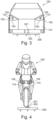
- Fig. 3 shows a schematic representation of a front area of a car dummy as dummy element 100.
- the dummy element 100 is mounted on a movable platform 300.
- the dummy element 100 has a first interface 301 and the movable platform 300 has a second interface 302, wherein the first interface 301 and the second interface 302 correspond to each other and are designed such that special data signals or energy can be exchanged between the platform 300 and the dummy element 100.
- Fig. 4 shows a schematic representation of a front area of a motorcycle dummy as dummy element 100.
- the dummy element 100 is attached to a movable platform 300.
- the dummy element 100 has a first interface 301 and the movable platform 300 has a second interface 302, wherein the first interface 301 and the second interface 302 correspond to each other and are designed such that special data signals or energy can be exchanged between the platform 300 and the dummy element 100.
- Fig. 5 and Fig. 6 show a section of a dummy element 100, wherein the opening 104 has a plurality of exit regions 203 for luminous elements 201, in particular LEDs.
- the LEDs can thus form a predetermined LED array.
- the exit regions 103 can be round, oval, rectilinear, or slit-shaped.
- the circuit board 201 is attached to the dummy body 101 towards the inner side 106.
- the luminous elements 201 protrude from the circuit board 101 towards the surrounding area 107.
- the luminous elements 201 can be located in the exit regions 203 or protrude from them towards the surrounding area 107.
- the fastening region 204 is slit-shaped and holds the circuit board 202 in a form-fitting manner.
- the dummy body 101 is shown in the undeformed state.
- Fig. 6 The dummy body 101 is shown in the deformed state. Due to the number of exit regions 203 in the dummy body 101, for example, it is readily deformable in this region.
- the circuit board 202 is designed to be elastically deformable and can deform along with the dummy body 101.
- the exemplary embodiment provides good elastic deformability of the dummy body 101 in the illumination region 102.
Landscapes
- Engineering & Computer Science (AREA)
- General Physics & Mathematics (AREA)
- Physics & Mathematics (AREA)
- General Engineering & Computer Science (AREA)
- Mechanical Engineering (AREA)
- Theoretical Computer Science (AREA)
- Business, Economics & Management (AREA)
- Educational Technology (AREA)
- Educational Administration (AREA)
- Arrangement Of Elements, Cooling, Sealing, Or The Like Of Lighting Devices (AREA)
- Non-Portable Lighting Devices Or Systems Thereof (AREA)
- Fastening Of Light Sources Or Lamp Holders (AREA)
- Lighting Device Outwards From Vehicle And Optical Signal (AREA)
Description
- Die vorliegende Erfindung betrifft ein Dummy-Element, insbesondere ein Dummy Fahrzeug mit einem Leuchtmittel.
- Zum Testen von Fahrerassistenzsystemen, insbesondere unter dem Gesichtspunkt des autonomen Fahrens, sind komplexe Verkehrssituationen abzubilden und zu simulieren. Dabei werden eine Vielzahl verschiedener Dummy-Elemente zueinander bewegt und insbesondere basierend auf GPS Daten gesteuert. Da zur Simulation komplexer Verkehrssituationen eine Vielzahl von Dummy-Elementen benötigt werden sowie häufig Unfälle zwischen einem Testfahrzeug und den Dummy-Elementen verursacht werden, müssen die Dummy-Elemente robust ausgebildet sein und auch nach einem Crash erneut wiederverwendet werden können.
- Um Dummy-Elemente, insbesondere Fahrzeugdummys, realitätsnah zu simulieren, werden aktive Komponenten, wie beispielsweise die Beleuchtungsvorrichtungen, d.h. die Scheinwerfer oder Blinker eines Fahrzeugs, in einem Dummykörper eingebaut. Dabei weisen die Beleuchtungsvorrichtungen entsprechende rigide Gehäuse und Rahmen auf, in denen ein Leuchtmittel eingebaut ist, um realitätsnah eine Scheinwerfervorrichtung eines Fahrzeugs zu simulieren. Die entsprechenden Gehäuse und Rahmen werden in entsprechend großen Öffnungen in dem Dummy-Element eingebaut. Da die Gehäuse und Rahmen in der Regel härter als das Material des Dummykörpers ist, werden häufig Schäden am Dummykörper selbst sowie an dem Testfahrzeug, mit dem ein Unfall herbeigeführt wurde, verursacht.
-
EP 3 242 120 A1 beschreibt eine Kollisionszielattrappe. Diese Kollisionszielattrappe bildet ein Fahrzeug nach und ist für nicht destruktive Kollisionsversuche, insbesondere zum Testen von Fahrerassistenzsystemen, vorgesehen. Die Kollisionszielattrappe umfasst eine Leuchteinrichtung, welche eine Beleuchtung eines Fahrzeugs simuliert. Diese Leuchteinrichtung umfasst eine stabile Hüllstruktur, welche das Leuchtmittel der Leuchteinrichtung umschließt und bei einer Kollision vor Beschädigungen schützt. - In
GB 2530307 A -
DE 10 2011 012 542 A1 beschreibt eine Testvorrichtung und ein Verfahren zur Simulation und Nachbildung von verschiedenen Fahrsituationen. Dabei wird ein Zielobjekt mit einem Führungsseil verbunden und von diesem bewegt. Im Fall einer simulierten Kollision eines Versuchsfahrzeugs mit dem Zielobjekt wird das Zielobjekt von dem Führungsseil abgekoppelt, sobald ein Belastungsschwellwert überschritten ist. - Es ist eine Aufgabe der vorliegenden Erfindung, eine Beleuchtungsvorrichtung robust und realitätsnah in einem Dummy-Element auszubilden.
- Diese Aufgabe wird mit Merkmal des unabhängigen Anspruchs gelöst.
- Gemäß einem ersten Aspekt wird ein Dummy-Element, insbesondere ein Dummy-Fahrzeug, beschrieben. Das Dummy-Element weist einen Dummykörper mit einem Beleuchtungsbereich, welcher eine zu simulierende Beleuchtungsvorrichtung eines zu simulierenden Elements, insbesondere eines Fahrzeugs, simuliert, auf. Ferner weist das Dummy-Element ein Leuchtmittel auf, welches gehäuselos ausgebildet ist, wobei der Dummykörper im Beleuchtungsbereich eine Öffnung aufweist, in welcher das Leuchtmittel angeordnet ist. Um das Leuchtmittel selbst sind kein Gehäuse und kein Rahmen, welche in der Öffnung vorliegen, ausgebildet.
- Gemäß einer beispielhaften Ausführungsform ist das Dummy-Element ein Zweirad, ein Motorrad oder ein Fahrrad, ein Kraftfahrzeug, besondere ein Pkw oder ein Lkw, ein menschlicher Dummy oder ein tierischer Dummy.
- Der Beleuchtungsbereich und das Leuchtmittel simulieren insbesondere Scheinwerfer, Blinker oder Bremslichter eines Fahrzeugs. Beispielsweise kann der Beleuchtungsbereich und das Leuchtmittel ebenfalls eine Stirnleuchte eines menschlichen Dummys simulieren.
- Das Leuchtmittel ist gehäuselos bzw. rahmenlos ausgebildet. Unter gehäuselos bzw. rahmenlos wird insbesondere verstanden, dass um das Leuchtmittel selbst kein Gehäuse und kein Rahmen, welche in der Öffnung vorliegen, ausgebildet sind. In der Öffnung befindet sich ausschließlich das Leuchtmittel, wie beispielsweise eine LED oder Glühbirne. Aufgrund einer Verformung des Grundkörpers im Falle eines Aufpralls wird somit eine Beschädigung von starren Bauteilen eines Leuchtmittels, wie beispielsweise dessen Gehäuse oder dessen Rahmen, verhindert.
- Der Dummykörper weist somit keine Ausbuchtung auf, in welcher üblicherweise eine Scheinwerfergehäuse oder ein Scheinwerferrahmen vorliegt, sondern lediglich eine kleinere Öffnung, in welcher ausschließlich das Leuchtmittel vorliegt.
- Ferner können in dem Beleuchtungsbereich, insbesondere an dessen Oberfläche, Reflektoren oder Spiegelelemente angeordnet werden, beispielsweise mittels Klebens.
- Gemäß einer beispielhaften Ausführungsform weist der Beleuchtungsbereich auf dessen Oberfläche graphische Konturen auf, welche z.B. einen Rahmen der zu simulierenden Beleuchtungsvorrichtung abbilden. Zur möglichst realen Simulation des Leuchtmittels können graphische Konturen den Rahmen oder das Gehäuse der zu simulierenden Beleuchtungsvorrichtung nachbilden.
- Gemäß einer beispielhaften Ausführungsform ist das Leuchtmittel mittels einer Presspassung in der Öffnung befestigt.
- Gemäß einer beispielhaften Ausführungsform bilden die Öffnung und das Leuchtmittel eine Spielpassung aus, sodass das Leuchtmittel schubladenartig in die Öffnung einschiebbar ist.
- Gemäß einer beispielhaften Ausführungsform ist das Leuchtmittel mittels einer Klebeverbindung in der Öffnung befestigt.
- Gemäß einer beispielhaften Ausführungsform ist das Leuchtmittel mittels eines Formschlusses in der Öffnung befestigt.
- Gemäß einer beispielhaften Ausführungsform weist das Leuchtmittel einen Leuchtkörper und eine Platine auf, wobei der Leuchtkörper von der Platine hervorragt.
- Gemäß einer beispielhaften Ausführungsform ist die Platine elastisch verformbar ausgebildet.
- Zum Beispiel kann die Platine ein flexibles (insbesondere bedrucktes) Band oder flexible (insbesondere bedruckte) Folie sein, welche zum Beispiel elektronische Leiterbahnen und elektronische Komponenten (z.B. LED-Elemente) aufweisen. Die Platine kann somit elastisch oder flexibel bzw. plastisch verformbar ausgebildet werden. Kommt es z.B. zu einer Kollision zweier Dummykörper, so kann sich die verformbare Platine elastisch oder plastisch verformen, ohne dabei Schaden zu nehmen. Danach kann sich die verformbare Platine wieder in einen Ausgangszustand (Ausgangsform) bringen lassen. Im Rahmen dieses Dokuments kann unter dem Begriff "verformbar" also insbesondere eine Eigenschaft verstanden werden, aufgrund der sich ein Körper nach einer zu einer Verformung führenden Krafteinwirkung wieder in eine Ausgangsform zurückbringen lässt oder selbsttätig zurückbringt. Dies hat den Vorteil, dass z.B. im Rahmen eines Crash-Tests beschädigte Elemente eines Dummykörpers wiederverwendet werden können und derartige Tests somit effizient und günstig durchgeführt werden können.
- Gemäß einer beispielhaften Ausführungsform ist die Platine innerhalb der Öffnung des Dummykörpers befestigt und der Leuchtkörper ragt aus der Öffnung heraus bzw. hervor. Mit anderen Worten kann die Öffnung als Bohrung in den Dummykörper vorgesehen werden, wobei die Platine in der Bohrung vorliegt und der Leuchtkörper im Bereich der Öffnung. Dabei kann der Leuchtkörper innerhalb der Öffnung vorliegen oder aus der Öffnung herausragen.
- Wenn der Leuchtkörper aus der Öffnung hervorragt, hat das den Vorteil, dass ein realitätsnaher Lichtkegel erzeugt wird. Somit kann eine Simulation, für die der Dummykörper verwendet wird, verbessert werden.
- Gemäß einer beispielhaften Ausführungsform weist die Öffnung in dem Dummykörper einen Austrittsbereich, durch welchen der Leuchtkörper (von dem Befestigungsbereich gesehen) nach außen ragt, und in dem Dummykörper einen Befestigungsbereich, an welchen die Platine vorliegt, auf.
- Der Austrittsbereich wird innerhalb des Dummykörpers gebildet und beschreibt den Bereich innerhalb des Dummykörpers, in welchem der Leuchtkörper, beispielsweise die LED oder die LEDs, vorliegt.
- Gemäß einer beispielhaften Ausführungsform weist die Öffnung in dem Dummykörper einen Austrittsbereich, in welchen der auf der Platine befestigte Leuchtkörper, insbesondere LED, hineinragt, und in dem Dummykörper einen Befestigungsbereich aufweist, in welchem die Platine vorliegt. Der Leuchtkörper liegt dabei vollständig innerhalb des Austrittsbereichs und ragt nicht aus der Öffnung in Richtung Umgebung heraus.
- Die Öffnung kann in einer weiteren beispielhaften Ausführungsform als lichttransparente Öffnung verstanden werden. Dies bedeutet, dass der Austrittsbereich beispielsweise durch ein zusätzliches lichttransparentes Material gefüllt ist oder durch einen lichttransparenten Bereich des Dummykörpers abgedeckt ist. Licht der Leuchtkörper, insbesondere der LEDs, strahlt somit durch die geschlossene Öffnung des Dummykörpers in die Umgebung.
- Gemäß einer beispielhaften Ausführungsform ist der Öffnungsdurchmesser des Austrittsbereichs kleiner als der Öffnungsdurchmesser des Befestigungsbereichs, sodass der Befestigungsbereich einen Hinterschnitt bildet, wobei der Dummykörper derart elastisch verformbar ausgebildet ist, dass die Platine durch den Austrittsbereich hindurchdrückbar ist und bei Vorliegen in dem Befestigungsbereich einen Formschluss zur Befestigung des Leuchtmittels ausbildet.
- Gemäß einer beispielhaften Ausführungsform weist das Leuchtmittel mehrere Leuchtkörper, insbesondere LEDs, auf, die an der Platine gekoppelt (und insbesondere auf einer Oberfläche der Platine befestigt sind und von dieser hervorragen) sind, wobei die Öffnung in dem Dummykörper mehrere Austrittsbereiche aufweist, wobei in jedem Austrittsbereich einer der Leuchtkörper angeordnet ist.
- Die Leuchtkörper liegen dabei vollständig innerhalb der entsprechenden Austrittsbereiche und ragen nicht aus der Öffnung bzw. den Austrittsbereichen in Richtung Umgebung des Dummykörpers heraus. Alternativ können die Leuchtkörper derart angeordnet sein, dass die Leuchtkörper sich durch die Austrittsbereiche hindurcherstrecken und aus der Öffnung in die Umgebung herausragen.
- Gemäß einer beispielhaften Ausführungsform ist die Öffnung eine Durchgangsöffnung und verbindet einen Innenbereich des Dummykörpers mit der Oberfläche des Beleuchtungsbereichs, wobei das Leuchtmittel von innen durch die Öffnungen hindurchsteckbar ist.
- Gemäß einer beispielhaften Ausführungsform weist das Leuchtmittel eine LED, insbesondere eine LED-Matrix, auf.
- Gemäß einer beispielhaften Ausführungsform ist der Dummykörper ein geschäumter Kunststoff.
- Gemäß einer beispielhaften Ausführungsform sind die graphischen Konturen mittels eines Farbmittels auf der Oberfläche des Beleuchtungsbereichs aufgetragen.
- Gemäß einer beispielhaften Ausführungsform sind die graphischen Konturen mittels Aufklebern auf der Oberfläche des Beleuchtungsbereichs aufgetragen sind.
- Gemäß einer beispielhaften Ausführungsform ist das Leuchtmittel Versorgungskabel aufweist, an welchen eine Energiequelle anschließbar.
- Gemäß einer beispielhaften Ausführungsform weist das Leuchtmittel eine Batterie als Energiequelle auf.
- Gemäß einer beispielhaften Ausführungsform weist das Leuchtmittel eine Induktionsspule auf, mittels welcher Energie für das Leuchtmittel zuführbar ist.
- Gemäß einer beispielhaften Ausführungsform weist das Leuchtmittel einen Signaltransmitter auf, wobei der Signaltransmitter eingerichtet ist Steuersignale zur Steuerung des Leuchtmittels zu empfangen.
- Gemäß einer beispielhaften Ausführungsform weist das Leuchtmittel einen Beschleunigungssensor auf, sodass Beschleunigungen und Verzögerungen messbar sind.
- Gemäß einem weiteren Ausführungsbeispiel weist das Dummy-Element eine Kühlvorrichtung auf. Die Kühlvorrichtung kann auf der dem Leuchtkörper abgewandten Seite der Platine eine Kühlvorrichtung thermisch gekoppelt sein. Die Kühlvorrichtung kann zum Beispiel eine Wasserkühlung, eine Luftkühlung oder eine thermoelektrische Kühlung (insbesondere eine Peltier-Element) aufweisen. Auch kann die Kühlvorrichtung eine Kombination verschiedener Kühlungen vorteilhaft aufweisen. Die durch den Leuchtkörper produzierte Abwärme kann so effizient abgeführt werden. Dies hat den Vorteil, dass die Lebensdauer des Leuchtkörpers sowie der Platine verlängert wird und eine sichere und zuverlässige Nutzung eines Leuchtmittels, welches einen Leuchtkörper und/oder eine Platine aufweist, gewährleistet ist.
- Die Kühlvorrichtung weist beispielsweise einen Kühlkörper auf, welcher lösbar, beispielsweise mittels einer Schraubverbindung, oder mittels einer Klebeverbindung an einer Seite der Platine befestigt und somit thermisch gekoppelt ist. Zwischen dem Kühlkörper und der Platine kann beispielsweise eine wärmeleitende Schicht, welche beispielsweise mittels einer Wärmeleitpaste gebildet wird, vorgesehen werden. Der Kühlkörper kann ferner Fluidleitungen aufweisen, durch welche ein Kühlmedium, wie beispielsweise eine Kühlflüssigkeit oder ein Kühlgas, befördert wird.
- Gemäß einem weiteren Aspekt der vorliegenden Erfindung wird ein System zum Bewegen eines Dummy-Elements beschrieben. Das System weist ein oben beschriebenes Dummy-Element und eine verfahrbare Plattform auf, wobei das Dummy-Element auf der verfahrbaren Plattform befestigt ist.
- Gemäß einer weiteren beispielhaften Ausführungsform des Systems weist das Dummy-Element eine erste Schnittstelle und die verfahrbare Plattform eine zweite Schnittstelle auf, wobei die erste Schnittstelle und die zweite Schnittstelle korrespondieren zueinander derart ausgebildet sind, dass besondere Datensignale oder Energie zwischen der Plattform und dem Dummy-Element austauschbar sind.
- Die Schnittstellen können beispielsweise zum Übertragen von Energie zwischen dem Dummy-Element und der Plattform ausgebildet sein. So können die Schnittstellen beispielsweise korrespondierende Spulen ausbilden, sodass induktiv Energie übertragen werden kann. Ferner können die Schnittstellen elektrisch leitende Schleifkontakte ausbilden. Ferner können die Schnittstellen korrespondierende Stecker/Boxenverbindungen ausbilden. Ferner können die Schnittstellen zum Austausch von Datensignalen dienen, sodass beispielsweise Steuersignale für das Leuchtmittel übertragen werden können oder Zustandsdaten des Leuchtmittels an die Plattform übertragen werden.
- Es wird darauf hingewiesen, dass die hier beschriebenen Ausführungsformen lediglich eine beschränkte Auswahl an möglichen Ausführungsvarianten der Erfindung darstellen. So ist es möglich, die Merkmale einzelner Ausführungsformen in geeigneter Weise miteinander zu kombinieren, so dass für den Fachmann mit den hier expliziten Ausführungsvarianten eine Vielzahl von verschiedenen Ausführungsformen als offensichtlich offenbart anzusehen sind. Insbesondere sind einige Ausführungsformen der Erfindung mit Vorrichtungsansprüchen und andere Ausführungsformen der Erfindung mit Verfahrensansprüchen beschrieben. Dem Fachmann wird jedoch bei der Lektüre dieser Anmeldung sofort klar werden, dass, sofern nicht explizit anders angegeben, zusätzlich zu einer Kombination von Merkmalen, die zu einem Typ von Erfindungsgegenstand gehören, auch eine beliebige Kombination von Merkmalen möglich ist, die zu unterschiedlichen Typen von Erfindungsgegenständen gehören.
- Im Folgenden werden zur weiteren Erläuterung und zum besseren Verständnis der vorliegenden Erfindung Ausführungsbeispiele unter Bezugnahme auf die beigefügten Zeichnungen näher beschrieben. Es zeigen:
-
Fig. 1 eine schematische Darstellung eines Ausschnitts eines Dummy-Elements, wobei die Öffnung als Durchgangsöffnung ausgebildet ist, gemäß einer beispielhaften Ausführungsform der vorliegenden Erfindung. -
Fig. 2 eine schematische Darstellung eines Ausschnitts eines Dummy-Elements, wobei die Öffnung als Sackloch mit Hinterschnitt ausgebildet ist, gemäß einer beispielhaften Ausführungsform der vorliegenden Erfindung. -
Fig. 3 eine schematische Darstellung eines Frontbereichs eines Autodummys, gemäß einer beispielhaften Ausführungsform der vorliegenden Erfindung. -
Fig. 4 eine schematische Darstellung eines Frontbereichs eines Motorraddummys, gemäß einer beispielhaften Ausführungsform der vorliegenden Erfindung. -
Fig. 5 und 6 schematische Darstellungen eines Ausschnitts eines Dummy-Elements, welches mehrere Öffnungen für Leuchtkörper aufweist gemäß einer beispielhaften Ausführungsform der vorliegenden Erfindung. - Gleiche oder ähnliche Komponenten in unterschiedlichen Figuren sind mit gleichen Bezugsziffern versehen. Die Darstellungen in den Figuren sind schematisch.
-
Fig. 1 zeigt eine schematische Darstellung eines Ausschnitts eines Dummy-Elements 100, wobei die Öffnung 104 als Durchgangsöffnung ausgebildet ist. Das Dummy-Element 100 ist beispielsweise ein Kraftfahrzeug, wobei inFig. 1 eine Schnittdarstellung des Frontbereichs dargestellt wird. Das Dummy-Element 100 weist einen Dummykörper 101 mit einem Beleuchtungsbereich 102 auf, welcher eine zu simulierende Beleuchtungsvorrichtung eines zu simulierenden Elements, insbesondere eines Fahrzeugs, simuliert. Der Beleuchtungsbereich 102 weist auf dessen Oberfläche graphische Konturen 103, welche einen Rahmen der zu simulierenden Beleuchtungsvorrichtung abbilden, und ein Leuchtmittel 110 auf. Das Leuchtmittel 110 ist gehäuselos ausgebildet. Der Dummykörper 101 weist im Beleuchtungsbereich 102 eine Öffnung 104 auf, in welcher das Leuchtmittel 110 angeordnet ist. - Der Beleuchtungsbereich 102 und das Leuchtmittel 110 simulieren insbesondere Scheinwerfer, Blinker oder Bremslichter eines Fahrzeugs.
- Die Öffnung 104 ist z.B. eine Durchgangsöffnung und verbindet einen Innenbereich 106 des Dummykörpers 101 mit der Oberfläche 105 des Beleuchtungsbereichs 102, welche zur Umgebung 107 des Dummy-Elements 100 zeigt. Das Leuchtmittel 110 ist von innen durch die Öffnungen 104 hindurchsteckbar.
- Das Leuchtmittel 110 Versorgungskabel aufweist, an welchen eine Energiequelle 109 anschließbar ist.
- Das Leuchtmittel 110 weist ferner einen Signaltransmitter 111 auf, wobei der Signaltransmitter 111 eingerichtet ist Steuersignale zur Steuerung des Leuchtmittels 110 zu empfangen.
-
Fig. 2 zeigt eine schematische Darstellung eines Ausschnitts eines Dummy-Elements 100, wobei die Öffnung 104 als Sackloch mit Hinterschnitt ausgebildet ist. Das Dummy-Element 100 ist beispielsweise ein Kraftfahrzeug, wobei inFig. 2 eine Schnittdarstellung des Frontbereichs dargestellt wird. Das Leuchtmittel 110 ist hier mittels eines Formschlusses in der Öffnung 104 befestigt. - Das Leuchtmittel 110 weist einen Leuchtkörper 201 und eine Platine 202 auf, wobei der Leuchtkörper 201 von der Platine 202 hervorragt. Eine entsprechende Ausführung des Leuchtmittels 110 kann auch in dem Durchgangsloch 104 aus
Fig. 1 eingesetzt werden. Die Platine 202 ist insbesondere elastisch verformbar ausgebildet, sodass sich diese elastisch verformt. - Die Platine 202 ist innerhalb der Öffnung 104 des Dummykörpers 101 befestigt und der Leuchtkörper 201 ragt aus der Öffnung 104 heraus bzw. hervor. Mit anderen Worten kann die Öffnung 104 als Bohrung in den Dummykörper 101 vorgesehen werden, wobei die Platine 202 in der Bohrung vorliegt und der Leuchtkörper 201 im Bereich der Öffnung 104 vorliegt. Dabei kann der Leuchtkörper 201 innerhalb der Öffnung 104 vorliegen oder aus der Öffnung 104 herausragen.
- Die Öffnung 104 weist in dem Dummykörper 101 einen Austrittsbereich 203, durch welchen der Leuchtkörper 201 nach außen ragt, und in dem Dummykörper 101 einen Befestigungsbereich 204, an welchen die Platine 202 vorliegt, auf. Der Öffnungsdurchmesser des Austrittsbereichs 203 ist kleiner als der Öffnungsdurchmesser des Befestigungsbereichs 204, sodass der Befestigungsbereich 204 einen Hinterschnitt bildet. Der Dummykörper 101 ist derart elastisch verformbar ausgebildet, dass die Platine 202, welche selbst elastisch verformbar sein kann, durch den Austrittsbereich 203 hindurchdrückbar ist und bei Vorliegen in dem Befestigungsbereich 204 einen Formschluss zur Befestigung des Leuchtmittels 110 ausbildet.
- Zusätzlich kann gemäß einem Ausführungsbeispiel der vorliegenden Erfindung auf der dem Leuchtkörper 201 abgewandten Seite der Platine 202 eine Kühlvorrichtung thermisch gekoppelt sein. Die Kühlvorrichtung kann zum Beispiel eine Wasserkühlung, eine Luftkühlung oder eine thermoelektrische Kühlung (insbesondere eine Peltier-Element) aufweisen. Auch kann die Kühlvorrichtung eine Kombination verschiedener Kühlungen vorteilhaft aufweisen.
-
Fig. 3 zeigt eine schematische Darstellung eines Frontbereichs eines Autodummys als Dummy-Element 100. Das Dummy-Element 100 ist auf einer verfahrbaren Plattform 300 befestigt. - Das Dummy-Element 100 weist eine erste Schnittstelle 301 und die verfahrbare Plattform 300 eine zweite Schnittstelle 302 auf, wobei die erste Schnittstelle 301 und die zweite Schnittstelle 302 korrespondieren zueinander derart ausgebildet sind, dass besondere Datensignale oder Energie zwischen der Plattform 300 und dem Dummy-Element 100 austauschbar sind.
-
Fig. 4 zeigt eine schematische Darstellung eines Frontbereichs eines Motorraddummys als Dummy-Element 100. Das Dummy-Element 100 ist auf einer verfahrbaren Plattform 300 befestigt. - Das Dummy-Element 100 weist eine erste Schnittstelle 301 und die verfahrbare Plattform 300 eine zweite Schnittstelle 302 auf, wobei die erste Schnittstelle 301 und die zweite Schnittstelle 302 korrespondieren zueinander derart ausgebildet sind, dass besondere Datensignale oder Energie zwischen der Plattform 300 und dem Dummy-Element 100 austauschbar sind.
-
Fig. 5 und Fig. 6 zeigen einen Ausschnitt eines Dummy-Elements 100, wobei die Öffnung 104 mehrere Austrittsbereiche 203 für Leuchtkörper 201, insbesondere LEDs, aufweist. Die LEDs können somit einen vorbestimmten LED Array bilden. Die Austrittsbereiche 103 können dabei rund, oval oder geradlinig bzw. schlitzförmige ausgebildet werden. In Richtung Innenseite 106 ist die Platine 201 an dem Dummykörper 101 befestigt. Von der Platine 101 ragen die Leuchtkörper 201 in Richtung Umgebung 107. Die Leuchtkörper 201 können sich dabei in den Austrittsbereichen 203 befinden oder aus diesen in Richtung Umgebung 107 hervorragen. Der Befestigungsbereich 204 ist dabei schlitzförmige ausgebildet und hält die Platine 202 formschlüssig fest. - In
Fig. 5 ist der Dummykörper 101 im nicht verformten Zustand dargestellt. InFig. 6 ist der Dummykörper 101 im verformten Zustand dargestellt. Durch die Anzahl der Austrittsbereiche 203 in dem Dummykörper 101 ist dieser beispielsweise in diesem Bereich gut verformbar. Ferner ist die Platine 202 elastisch verformbar ausgebildet und kann sich mit dem Dummykörper 101 mitverformen. Somit wird mit dem Ausführungsbeispiel eine gute elastische Verformbarkeit des Dummykörpers 101 im Beleuchtungsbereich 102 geschaffen. - Ergänzend ist darauf hinzuweisen, dass "umfassend" keine anderen Elemente oder Schritte ausschließt und "eine" oder "ein" keine Vielzahl ausschließt. Ferner sei darauf hingewiesen, dass Merkmale oder Schritte, die mit Verweis auf eines der obigen Ausführungsbeispiele beschrieben worden sind, auch in Kombination mit anderen Merkmalen oder Schritten anderer oben beschriebener Ausführungsbeispiele verwendet werden können.
-
- 100
- Dummy-Element
- 101
- Dummykörper
- 102
- Beleuchtungsbereich
- 103
- graphische Konturen
- 104
- Öffnung
- 105
- Oberfläche des Beleuchtungsbereichs
- 106
- Innenraum
- 107
- Umgebung
- 108
- Versorgungskabel
- 109
- Energiequelle
- 110
- Leuchtmittel
- 111
- Signaltransmitter
- 201
- Leuchtkörper
- 202
- Platine
- 203
- Austrittsbereich
- 204
- Befestigungsbereich
- 300
- verfahrbare Plattform
- 301
- erste Schnittstelle
- 302
- zweite Schnittstelle
Claims (15)
- Dummy-Element (100), insbesondere ein Dummy-Fahrzeug, aufweisendeinen Dummykörper (101) mit einem Beleuchtungsbereich (102), welcher eine zu simulierende Beleuchtungsvorrichtung eines zu simulierenden Elements, insbesondere eines Fahrzeugs, simuliert,ein Leuchtmittel (110),
wobei der Dummykörper (101) im Beleuchtungsbereich (102) eine Öffnung (104) aufweist, in welcher das Leuchtmittel (110) angeordnet ist,
dadurch gekennzeichnet, dassdas Leuchtmittel (110) gehäuselos ausgebildet ist, wobei um das Leuchtmittel (110) selbst kein Gehäuse und kein Rahmen, welche in der Öffnung (104) vorliegen, ausgebildet sind. - Dummy-Element (100) gemäß Anspruch 1,
wobei der Beleuchtungsbereich (102) auf dessen Oberfläche (105) graphische Konturen (103) aufweist, welche insbesondere einen Rahmen der zu simulierenden Beleuchtungsvorrichtung abbilden. - Dummy-Element (100) gemäß Anspruch 1 oder 2,wobei das Leuchtmittel (110) mittels einer Presspassung in der Öffnung (104) befestigt ist,wobei die Öffnung (104) und das Leuchtmittel (110) eine Spielpassung ausbilden, sodass das Leuchtmittel (110) schubladenartig in die Öffnung (104) einschiebbar ist,wobei das Leuchtmittel (110) mittels einer Klebeverbindung in der Öffnung (104) befestigt ist, und/oderwobei das Leuchtmittel (110) mittels eines Formschlusses in der Öffnung (104) befestigt ist.
- Dummy-Element (100) gemäß einem der Ansprüche 1 bis 3,wobei das Leuchtmittel (110) einen Leuchtkörper (201) und eine Platine (202) aufweist,wobei der Leuchtkörper (201) von der Platine (202) hervorragt.
- Dummy-Element (100) gemäß Anspruch 4,wobei die Platine (202) flexibel, insbesondere elastisch, verformbar ausgebildet ist, und/oderwobei die Platine (202) in der Öffnung (104) des Dummykörpers (101) befestigt ist und der Leuchtkörper (201) aus der Öffnung (104) hervorragt.
- Dummy-Element gemäß Anspruch 4 oder 5,wobei die Öffnung (104) in dem Dummykörper (101) einen Austrittsbereich (203), durch welchen der Leuchtkörper (201) nach außen ragt, und in dem Dummykörper (101) einen Befestigungsbereich (204) aufweist, an welchen die Platine (202) vorliegt, oderwobei die Öffnung (104) in dem Dummykörper (101) einen Austrittsbereich (203), in welchen der auf der Platine (202) befestigte Leuchtkörper (201), insbesondere LED, hineinragt und in dem Austrittsbereich (203) vollständig vorliegt, und in dem Dummykörper (101) einen Befestigungsbereich (204) aufweist, in welchem die Platine (202) vorliegt.
- Dummy-Element (100) gemäß einem der Ansprüche 4 bis 6,wobei der Öffnungsdurchmesser eines Austrittsbereichs (203) kleiner ist als der Öffnungsdurchmesser des Befestigungsbereichs (204), sodass der Befestigungsbereich (204) einen Hinterschnitt bildet,wobei der Dummykörper (101) derart elastisch verformbar ausgebildet ist, dass die Platine (202) durch den Austrittsbereich (203) hindurchdrückbar ist und bei Vorliegen in dem Befestigungsbereich (204) einen Formschluss zur Befestigung des Leuchtmittels (110) ausbildet, und/oderwobei das Leuchtmittel (110) mehrere Leuchtkörper (201), insbesondere LEDs, aufweist, die an der Platine (202) gekoppelt sind,wobei die Öffnung (104) in dem Dummykörper (101) mehrere Austrittsbereiche (203) aufweist,wobei in jedem Austrittsbereich (203) einer der Leuchtkörper (201) angeordnet ist.
- Dummy-Element (100) gemäß einem der Ansprüche 4 bis 7, ferner aufweisend
eine Kühlvorrichtungwobei auf der dem Leuchtkörper (201) abgewandten Seite der Platine (202) die Kühlvorrichtung thermisch gekoppelt ist,wobei die Kühlvorrichtung insbesondere aufweist zumindest eine aus der Gruppe von:eine Wasserkühlung;eine Luftkühlung; undeine thermoelektrische Kühlung, insbesondere eine Peltier-Element. - Dummy-Element (100) gemäß einem der Ansprüche 1 bis 8,wobei die Öffnung (104) eine Durchgangsöffnung ist und einen Innenbereich des Dummykörpers (101) mit der Oberfläche (105) des Beleuchtungsbereichs (102) verbindet,wobei das Leuchtmittel (110) von innen durch die Öffnungen (104) hindurchsteckbar ist.
- Dummy-Element (100) gemäß einem der Ansprüche 1 bis 9,
wobei das Leuchtmittel (110) eine LED, insbesondere eine LED Matrix, aufweist. - Dummy-Element (100) gemäß einem der Ansprüche 1 bis 10,
wobei der Dummykörper (101) ein geschäumter Kunststoff ist. - Dummy-Element (100) gemäß einem der Ansprüche 1 bis 11,
wobei die graphischen Konturen (103) mittels eines Farbmittels auf der Oberfläche (105) des Beleuchtungsbereichs (102) aufgetragen sind, und/oder wobei die graphischen Konturen (103) mittels Aufklebern auf der Oberfläche (105) des Beleuchtungsbereichs (102) aufgetragen sind. - Dummy-Element (100) gemäß einem der Ansprüche 1 bis 12,wobei das Leuchtmittel (110) Versorgungskabel (108) aufweist, an welchen eine Energiequelle (109) anschließbar ist.wobei das Leuchtmittel (110) insbesondere eine Batterie als Energiequelle (109) aufweist.
- Dummy-Element (100) gemäß einem der Ansprüche 1 bis 13, ferner aufweisend zumindest eines der folgenden Merkmale:wobei das Leuchtmittel (110) eine Induktionsspule aufweist, mittels welcher Energie für das Leuchtmittel (110) zuführbar ist,wobei das Leuchtmittel (110) einen Signaltransmitter (111) aufweist, wobei der Signaltransmitter (111) eingerichtet ist Steuersignale zur Steuerung des Leuchtmittels (110) zu empfangen,wobei das Leuchtmittel (110) einen Beschleunigungssensor aufweist, sodass Beschleunigungen und Verzögerungen messbar sind.
- System zum Bewegen eines Dummy-Elements (100), das System aufweisendein Dummy-Element (100) gemäß einem der Ansprüche 1 bis 14,eine verfahrbare Plattform (300),wobei das Dummy-Element (100) auf der verfahrbaren Plattform (300) befestigt ist,wobei das Dummy-Element (100) insbesondere eine erste Schnittstelle (301) und die verfahrbare Plattform (300) insbesondere eine zweite Schnittstelle (302) aufweist,wobei die erste Schnittstelle (301) und die zweite Schnittstelle (302) korrespondieren zueinander derart ausgebildet sind, dass besondere Datensignale oder Energie zwischen der Plattform (300) und dem Dummy-Element (100) austauschbar sind.
Applications Claiming Priority (2)
| Application Number | Priority Date | Filing Date | Title |
|---|---|---|---|
| DE102019115539.8A DE102019115539A1 (de) | 2019-06-07 | 2019-06-07 | Dummy-Element mit einem Leuchtmittel |
| PCT/EP2020/065665 WO2020245387A1 (de) | 2019-06-07 | 2020-06-05 | Dummy-element mit einem leuchtmittel |
Publications (2)
| Publication Number | Publication Date |
|---|---|
| EP3980746A1 EP3980746A1 (de) | 2022-04-13 |
| EP3980746B1 true EP3980746B1 (de) | 2025-05-14 |
Family
ID=71016550
Family Applications (1)
| Application Number | Title | Priority Date | Filing Date |
|---|---|---|---|
| EP20731068.1A Active EP3980746B1 (de) | 2019-06-07 | 2020-06-05 | Dummy-element mit einem leuchtmittel |
Country Status (6)
| Country | Link |
|---|---|
| US (1) | US12103455B2 (de) |
| EP (1) | EP3980746B1 (de) |
| JP (1) | JP7608701B2 (de) |
| CN (1) | CN113853641B (de) |
| DE (1) | DE102019115539A1 (de) |
| WO (1) | WO2020245387A1 (de) |
Families Citing this family (2)
| Publication number | Priority date | Publication date | Assignee | Title |
|---|---|---|---|---|
| CN113879325B (zh) * | 2021-10-28 | 2024-03-12 | 中汽院智能网联科技有限公司 | 一种自动驾驶辅助测试装置、方法及系统 |
| DE102021129629A1 (de) | 2021-11-15 | 2023-05-17 | Bayerische Motoren Werke Aktiengesellschaft | Ständervorrichtung für ein Zweirad eines Überprüfungssystems zum Überprüfen eines Assistenzsystems eines Kraftfahrzeugs, sowie Überprüfungssystem |
Family Cites Families (20)
| Publication number | Priority date | Publication date | Assignee | Title |
|---|---|---|---|---|
| DE60028907T2 (de) * | 1999-11-24 | 2007-02-15 | Donnelly Corp., Holland | Rückspiegel mit Nutzfunktion |
| JP2007200697A (ja) * | 2006-01-26 | 2007-08-09 | Koito Mfg Co Ltd | 車輌用灯具 |
| KR101048132B1 (ko) * | 2008-11-07 | 2011-07-08 | 기아자동차주식회사 | 차량용 전방 검사장치 |
| KR20120041954A (ko) * | 2010-10-22 | 2012-05-03 | 에스엘 주식회사 | 차량용 램프 조립체 및 그 제조 방법 |
| DE102011012542A1 (de) | 2011-02-26 | 2012-08-30 | Continental Safety Engineering International Gmbh | Testvorrichtung und Verfahren |
| AT511217B1 (de) | 2011-05-18 | 2012-10-15 | 4A Engineering Gmbh | Dummy-objekt, insbesondere zur funktionsüberprüfung von fahrerassistenzsystemen in kraftfahrzeugen |
| GB2496443B (en) * | 2011-11-11 | 2016-03-30 | Autoliv Dev | A dummy test vehicle |
| DE102012207567B4 (de) | 2012-05-07 | 2015-02-19 | 4A Engineering Gmbh | Dummy-Objekt mit Extremitäten, die unter Ausnutzung ihrer Massenträgheit einen natürlichen Bewegungsverlauf nachbilden |
| DE102012110586A1 (de) * | 2012-10-15 | 2014-04-17 | Continental Safety Engineering International Gmbh | Verbindungsvorrichtung und Testanordnung |
| DE102013214936B4 (de) | 2013-03-22 | 2018-05-24 | 4Activesystems Gmbh | System und Verfahren zum Erzeugen von Kollisionen zwischen einem Fahrzeug und einem Testobjekt |
| AT516127B1 (de) * | 2014-07-28 | 2016-10-15 | Fame Tech Gmbh | Profilelement mit darin aufgenommenen Leuchtmitteln |
| GB2530307A (en) * | 2014-09-19 | 2016-03-23 | Johnson Electric Sa | LED lighting assembly |
| DE102015117358B4 (de) | 2015-10-12 | 2018-12-13 | 4Activesystems Gmbh | Elastisch verformbares Dummy-Fahrzeug zum Durchführen von Tests für Fahrerassistenzsysteme |
| DE102016108138A1 (de) * | 2016-05-02 | 2017-11-02 | DSD Dr. Steffan Datentechnik Ges.m.b.H. | Kollisionszielattrappe |
| DE102016112422B4 (de) | 2016-07-06 | 2019-11-28 | 4Activesystems Gmbh | Verfahrbare Plattform mit einem verformbaren Grundkörper zum Testen von Kollisionen oder kollisionsnahen Situationen |
| DE202016008728U1 (de) | 2016-07-06 | 2019-03-27 | 4Activesystems Gmbh | Leistungsstarke und witterungsbeständige Plattform für ein Testsystem zum Testen von Kollisionen oder kollisionsnahen Situationen |
| DE102016112518B4 (de) | 2016-07-07 | 2021-03-11 | 4Activesystems Gmbh | Dummy-Fahrzeug sowie Verfahren zum Durchführen von Tests für ein Fahrerassistenzsystem |
| US11027641B2 (en) * | 2017-10-09 | 2021-06-08 | AAC Enterprises LLC | Front grill with LED module lighting system |
| CN208766939U (zh) * | 2018-05-07 | 2019-04-19 | 东风汽车有限公司 | 一种智能试驾平台 |
| CN109594487B (zh) * | 2018-11-20 | 2024-12-03 | 台州市星标交通科技有限公司 | 一种地埋式道钉 |
-
2019
- 2019-06-07 DE DE102019115539.8A patent/DE102019115539A1/de not_active Withdrawn
-
2020
- 2020-06-05 CN CN202080036202.5A patent/CN113853641B/zh active Active
- 2020-06-05 US US17/616,660 patent/US12103455B2/en active Active
- 2020-06-05 JP JP2021562937A patent/JP7608701B2/ja active Active
- 2020-06-05 WO PCT/EP2020/065665 patent/WO2020245387A1/de not_active Ceased
- 2020-06-05 EP EP20731068.1A patent/EP3980746B1/de active Active
Also Published As
| Publication number | Publication date |
|---|---|
| US12103455B2 (en) | 2024-10-01 |
| JP2022535191A (ja) | 2022-08-05 |
| JP7608701B2 (ja) | 2025-01-07 |
| EP3980746A1 (de) | 2022-04-13 |
| CN113853641B (zh) | 2024-09-17 |
| DE102019115539A1 (de) | 2020-12-10 |
| CN113853641A (zh) | 2021-12-28 |
| US20220161711A1 (en) | 2022-05-26 |
| WO2020245387A1 (de) | 2020-12-10 |
Similar Documents
| Publication | Publication Date | Title |
|---|---|---|
| EP3242120B1 (de) | Kollisionszielattrappe | |
| EP3980746B1 (de) | Dummy-element mit einem leuchtmittel | |
| DE102007035474B4 (de) | System und Verfahren zur Funktionsprüfung eines Fahrerassistenzsystems | |
| EP0886462A2 (de) | Vorrichtung zur Aufnahme von elektrischen Bauteilen | |
| DE102010038639B4 (de) | Vorrichtung zum Testen eines Sicherheits- und/oder Fahrassistenzsystems | |
| AT513910B1 (de) | Verfahren zum Herstellen einer Leuchteinheit sowie Leuchteinheit | |
| DE102015016281A1 (de) | Windschutzscheibe eines Kraftfahrzeugs, System mit Windschutzscheibe sowie Kraftfahrzeug | |
| DE212018000180U1 (de) | Rückwärtsansicht-Baugruppe | |
| DE102008030208A1 (de) | Vorrichtung und Verfahren zum Erzeugen von Kollisionssituationen oder kollisionsnahen Situationen zwischen einem Testfahrzeug und einem Kollisionsobjekt und Einrichtung zur Funktionsprüfung eines Fahrerassistenzsystems | |
| EP3210444B1 (de) | Kraftfahrzeug-aussenleuchte | |
| EP3980744B1 (de) | Dummy-fahrzeug mit einer sensorsensitiven schicht | |
| DE10255301A1 (de) | Verfahren und Vorrichtung zum selektiven Betreiben von Beleuchtungseinrichtungen eines Anhängers für ein Kraftfahrzeug | |
| DE202016107063U1 (de) | Kennleuchtebalken-Vorrichtung | |
| DE102019121177A1 (de) | Anordnung eines Typenbezeichnungselements in einem Heckbereich eines Kraftwagens, Verfahren zum Anzeigen einer Typenbezeichnung eines Kraftwagens sowie Heckleuchte für einen Kraftwagen | |
| DE202017105205U1 (de) | Signalleuchte für Fahrzeuge | |
| DE102016100156B4 (de) | Testgerät für ein Fahrerassistenzsystem und Verfahren zur Durchführung einer Funktionsprüfung eines Fahrerassistenzsystems | |
| DE10158224B4 (de) | Mobiles optoelektronisches Testgerät für Kfz-Bremslichter, insbesondere an diversen Anhängerarten | |
| DE102004059742A1 (de) | Glasverbund, insbesondere Heckscheibe eines Kraftfahrzeugs, mit einer leuchtenden Funktionsschicht | |
| DE102024002689B3 (de) | Sensoranordnung für ein Fahrzeug, Fahrzeug und Luftfahrzeug | |
| DE102020202102B4 (de) | Lampenanordnung für ein Fahrzeug | |
| DE29804694U1 (de) | Zierstreifen für Fahrzeuge | |
| DE202025101700U1 (de) | Signalgeber für ein autonomes Fahrzeug zur Kommunikation eines Fahrzeugzustandes an externe Beobachter | |
| DE102015226478A1 (de) | Kollisionsfähige Fahrzeugattrappe zum Testen eines Umfeldsensors für ein Kraftfahrzeug | |
| EP4563438A1 (de) | Verfahren zum kuppeln von spurgeführten fahrzeugverbänden | |
| CH721900A2 (de) | Beleuchtung von Modellen |
Legal Events
| Date | Code | Title | Description |
|---|---|---|---|
| STAA | Information on the status of an ep patent application or granted ep patent |
Free format text: STATUS: UNKNOWN |
|
| STAA | Information on the status of an ep patent application or granted ep patent |
Free format text: STATUS: THE INTERNATIONAL PUBLICATION HAS BEEN MADE |
|
| PUAI | Public reference made under article 153(3) epc to a published international application that has entered the european phase |
Free format text: ORIGINAL CODE: 0009012 |
|
| STAA | Information on the status of an ep patent application or granted ep patent |
Free format text: STATUS: REQUEST FOR EXAMINATION WAS MADE |
|
| 17P | Request for examination filed |
Effective date: 20211126 |
|
| AK | Designated contracting states |
Kind code of ref document: A1 Designated state(s): AL AT BE BG CH CY CZ DE DK EE ES FI FR GB GR HR HU IE IS IT LI LT LU LV MC MK MT NL NO PL PT RO RS SE SI SK SM TR |
|
| DAV | Request for validation of the european patent (deleted) | ||
| DAX | Request for extension of the european patent (deleted) | ||
| STAA | Information on the status of an ep patent application or granted ep patent |
Free format text: STATUS: EXAMINATION IS IN PROGRESS |
|
| 17Q | First examination report despatched |
Effective date: 20240227 |
|
| GRAP | Despatch of communication of intention to grant a patent |
Free format text: ORIGINAL CODE: EPIDOSNIGR1 |
|
| STAA | Information on the status of an ep patent application or granted ep patent |
Free format text: STATUS: GRANT OF PATENT IS INTENDED |
|
| INTG | Intention to grant announced |
Effective date: 20250210 |
|
| GRAS | Grant fee paid |
Free format text: ORIGINAL CODE: EPIDOSNIGR3 |
|
| GRAA | (expected) grant |
Free format text: ORIGINAL CODE: 0009210 |
|
| STAA | Information on the status of an ep patent application or granted ep patent |
Free format text: STATUS: THE PATENT HAS BEEN GRANTED |
|
| AK | Designated contracting states |
Kind code of ref document: B1 Designated state(s): AL AT BE BG CH CY CZ DE DK EE ES FI FR GB GR HR HU IE IS IT LI LT LU LV MC MK MT NL NO PL PT RO RS SE SI SK SM TR |
|
| REG | Reference to a national code |
Ref country code: GB Ref legal event code: FG4D Free format text: NOT ENGLISH |
|
| REG | Reference to a national code |
Ref country code: CH Ref legal event code: EP |
|
| REG | Reference to a national code |
Ref country code: IE Ref legal event code: FG4D Free format text: LANGUAGE OF EP DOCUMENT: GERMAN |
|
| REG | Reference to a national code |
Ref country code: DE Ref legal event code: R096 Ref document number: 502020011055 Country of ref document: DE |
|
| PGFP | Annual fee paid to national office [announced via postgrant information from national office to epo] |
Ref country code: AT Payment date: 20250715 Year of fee payment: 6 |
|
| REG | Reference to a national code |
Ref country code: NL Ref legal event code: MP Effective date: 20250514 |
|
| PG25 | Lapsed in a contracting state [announced via postgrant information from national office to epo] |
Ref country code: ES Free format text: LAPSE BECAUSE OF FAILURE TO SUBMIT A TRANSLATION OF THE DESCRIPTION OR TO PAY THE FEE WITHIN THE PRESCRIBED TIME-LIMIT Effective date: 20250514 Ref country code: FI Free format text: LAPSE BECAUSE OF FAILURE TO SUBMIT A TRANSLATION OF THE DESCRIPTION OR TO PAY THE FEE WITHIN THE PRESCRIBED TIME-LIMIT Effective date: 20250514 Ref country code: PT Free format text: LAPSE BECAUSE OF FAILURE TO SUBMIT A TRANSLATION OF THE DESCRIPTION OR TO PAY THE FEE WITHIN THE PRESCRIBED TIME-LIMIT Effective date: 20250915 |
|
| PGFP | Annual fee paid to national office [announced via postgrant information from national office to epo] |
Ref country code: DE Payment date: 20250812 Year of fee payment: 6 |
|
| REG | Reference to a national code |
Ref country code: LT Ref legal event code: MG9D |
|
| PG25 | Lapsed in a contracting state [announced via postgrant information from national office to epo] |
Ref country code: NO Free format text: LAPSE BECAUSE OF FAILURE TO SUBMIT A TRANSLATION OF THE DESCRIPTION OR TO PAY THE FEE WITHIN THE PRESCRIBED TIME-LIMIT Effective date: 20250814 Ref country code: GR Free format text: LAPSE BECAUSE OF FAILURE TO SUBMIT A TRANSLATION OF THE DESCRIPTION OR TO PAY THE FEE WITHIN THE PRESCRIBED TIME-LIMIT Effective date: 20250815 |
|
| PG25 | Lapsed in a contracting state [announced via postgrant information from national office to epo] |
Ref country code: NL Free format text: LAPSE BECAUSE OF FAILURE TO SUBMIT A TRANSLATION OF THE DESCRIPTION OR TO PAY THE FEE WITHIN THE PRESCRIBED TIME-LIMIT Effective date: 20250514 Ref country code: PL Free format text: LAPSE BECAUSE OF FAILURE TO SUBMIT A TRANSLATION OF THE DESCRIPTION OR TO PAY THE FEE WITHIN THE PRESCRIBED TIME-LIMIT Effective date: 20250514 |
|
| PG25 | Lapsed in a contracting state [announced via postgrant information from national office to epo] |
Ref country code: BG Free format text: LAPSE BECAUSE OF FAILURE TO SUBMIT A TRANSLATION OF THE DESCRIPTION OR TO PAY THE FEE WITHIN THE PRESCRIBED TIME-LIMIT Effective date: 20250514 |
|
| PGFP | Annual fee paid to national office [announced via postgrant information from national office to epo] |
Ref country code: GB Payment date: 20250714 Year of fee payment: 6 |
|
| PG25 | Lapsed in a contracting state [announced via postgrant information from national office to epo] |
Ref country code: HR Free format text: LAPSE BECAUSE OF FAILURE TO SUBMIT A TRANSLATION OF THE DESCRIPTION OR TO PAY THE FEE WITHIN THE PRESCRIBED TIME-LIMIT Effective date: 20250514 |
|
| PG25 | Lapsed in a contracting state [announced via postgrant information from national office to epo] |
Ref country code: RS Free format text: LAPSE BECAUSE OF FAILURE TO SUBMIT A TRANSLATION OF THE DESCRIPTION OR TO PAY THE FEE WITHIN THE PRESCRIBED TIME-LIMIT Effective date: 20250814 |
|
| PG25 | Lapsed in a contracting state [announced via postgrant information from national office to epo] |
Ref country code: IS Free format text: LAPSE BECAUSE OF FAILURE TO SUBMIT A TRANSLATION OF THE DESCRIPTION OR TO PAY THE FEE WITHIN THE PRESCRIBED TIME-LIMIT Effective date: 20250914 |
|
| PG25 | Lapsed in a contracting state [announced via postgrant information from national office to epo] |
Ref country code: LV Free format text: LAPSE BECAUSE OF FAILURE TO SUBMIT A TRANSLATION OF THE DESCRIPTION OR TO PAY THE FEE WITHIN THE PRESCRIBED TIME-LIMIT Effective date: 20250514 |
|
| PG25 | Lapsed in a contracting state [announced via postgrant information from national office to epo] |
Ref country code: DK Free format text: LAPSE BECAUSE OF FAILURE TO SUBMIT A TRANSLATION OF THE DESCRIPTION OR TO PAY THE FEE WITHIN THE PRESCRIBED TIME-LIMIT Effective date: 20250514 Ref country code: SM Free format text: LAPSE BECAUSE OF FAILURE TO SUBMIT A TRANSLATION OF THE DESCRIPTION OR TO PAY THE FEE WITHIN THE PRESCRIBED TIME-LIMIT Effective date: 20250514 |
|
| PG25 | Lapsed in a contracting state [announced via postgrant information from national office to epo] |
Ref country code: CZ Free format text: LAPSE BECAUSE OF FAILURE TO SUBMIT A TRANSLATION OF THE DESCRIPTION OR TO PAY THE FEE WITHIN THE PRESCRIBED TIME-LIMIT Effective date: 20250514 |
|
| PG25 | Lapsed in a contracting state [announced via postgrant information from national office to epo] |
Ref country code: EE Free format text: LAPSE BECAUSE OF FAILURE TO SUBMIT A TRANSLATION OF THE DESCRIPTION OR TO PAY THE FEE WITHIN THE PRESCRIBED TIME-LIMIT Effective date: 20250514 |
|
| PG25 | Lapsed in a contracting state [announced via postgrant information from national office to epo] |
Ref country code: SK Free format text: LAPSE BECAUSE OF FAILURE TO SUBMIT A TRANSLATION OF THE DESCRIPTION OR TO PAY THE FEE WITHIN THE PRESCRIBED TIME-LIMIT Effective date: 20250514 Ref country code: RO Free format text: LAPSE BECAUSE OF FAILURE TO SUBMIT A TRANSLATION OF THE DESCRIPTION OR TO PAY THE FEE WITHIN THE PRESCRIBED TIME-LIMIT Effective date: 20250514 |
|
| REG | Reference to a national code |
Ref country code: CH Ref legal event code: H13 Free format text: ST27 STATUS EVENT CODE: U-0-0-H10-H13 (AS PROVIDED BY THE NATIONAL OFFICE) Effective date: 20260127 |
|
| PG25 | Lapsed in a contracting state [announced via postgrant information from national office to epo] |
Ref country code: IT Free format text: LAPSE BECAUSE OF FAILURE TO SUBMIT A TRANSLATION OF THE DESCRIPTION OR TO PAY THE FEE WITHIN THE PRESCRIBED TIME-LIMIT Effective date: 20250514 |
|
| PG25 | Lapsed in a contracting state [announced via postgrant information from national office to epo] |
Ref country code: LU Free format text: LAPSE BECAUSE OF NON-PAYMENT OF DUE FEES Effective date: 20250605 |
|
| REG | Reference to a national code |
Ref country code: DE Ref legal event code: R097 Ref document number: 502020011055 Country of ref document: DE |
|
| PG25 | Lapsed in a contracting state [announced via postgrant information from national office to epo] |
Ref country code: MC Free format text: LAPSE BECAUSE OF FAILURE TO SUBMIT A TRANSLATION OF THE DESCRIPTION OR TO PAY THE FEE WITHIN THE PRESCRIBED TIME-LIMIT Effective date: 20250514 |
|
| REG | Reference to a national code |
Ref country code: BE Ref legal event code: MM Effective date: 20250630 |
|
| PLBE | No opposition filed within time limit |
Free format text: ORIGINAL CODE: 0009261 |
|
| STAA | Information on the status of an ep patent application or granted ep patent |
Free format text: STATUS: NO OPPOSITION FILED WITHIN TIME LIMIT |
|
| REG | Reference to a national code |
Ref country code: CH Ref legal event code: L10 Free format text: ST27 STATUS EVENT CODE: U-0-0-L10-L00 (AS PROVIDED BY THE NATIONAL OFFICE) Effective date: 20260325 |
|
| PG25 | Lapsed in a contracting state [announced via postgrant information from national office to epo] |
Ref country code: IE Free format text: LAPSE BECAUSE OF NON-PAYMENT OF DUE FEES Effective date: 20250605 |
|
| PG25 | Lapsed in a contracting state [announced via postgrant information from national office to epo] |
Ref country code: BE Free format text: LAPSE BECAUSE OF NON-PAYMENT OF DUE FEES Effective date: 20250630 |
|
| PG25 | Lapsed in a contracting state [announced via postgrant information from national office to epo] |
Ref country code: FR Free format text: LAPSE BECAUSE OF NON-PAYMENT OF DUE FEES Effective date: 20250714 |
|
| 26N | No opposition filed |
Effective date: 20260217 |
|
| PG25 | Lapsed in a contracting state [announced via postgrant information from national office to epo] |
Ref country code: CH Free format text: LAPSE BECAUSE OF NON-PAYMENT OF DUE FEES Effective date: 20250630 |