EP3979897B1 - Verfahren, vorrichtungen und systeme zur bestimmung von augenparametern - Google Patents
Verfahren, vorrichtungen und systeme zur bestimmung von augenparametern Download PDFInfo
- Publication number
- EP3979897B1 EP3979897B1 EP20728489.4A EP20728489A EP3979897B1 EP 3979897 B1 EP3979897 B1 EP 3979897B1 EP 20728489 A EP20728489 A EP 20728489A EP 3979897 B1 EP3979897 B1 EP 3979897B1
- Authority
- EP
- European Patent Office
- Prior art keywords
- eye
- center
- camera
- eyeball
- expected
- Prior art date
- Legal status (The legal status is an assumption and is not a legal conclusion. Google has not performed a legal analysis and makes no representation as to the accuracy of the status listed.)
- Active
Links
Images


Classifications
-
- A—HUMAN NECESSITIES
- A61—MEDICAL OR VETERINARY SCIENCE; HYGIENE
- A61B—DIAGNOSIS; SURGERY; IDENTIFICATION
- A61B3/00—Apparatus for testing the eyes; Instruments for examining the eyes
- A61B3/10—Objective types, i.e. instruments for examining the eyes independent of the patients' perceptions or reactions
- A61B3/113—Objective types, i.e. instruments for examining the eyes independent of the patients' perceptions or reactions for determining or recording eye movement
-
- G—PHYSICS
- G02—OPTICS
- G02B—OPTICAL ELEMENTS, SYSTEMS OR APPARATUS
- G02B27/00—Optical systems or apparatus not provided for by any of the groups G02B1/00 - G02B26/00, G02B30/00
- G02B27/0093—Optical systems or apparatus not provided for by any of the groups G02B1/00 - G02B26/00, G02B30/00 with means for monitoring data relating to the user, e.g. head-tracking, eye-tracking
-
- G—PHYSICS
- G02—OPTICS
- G02B—OPTICAL ELEMENTS, SYSTEMS OR APPARATUS
- G02B27/00—Optical systems or apparatus not provided for by any of the groups G02B1/00 - G02B26/00, G02B30/00
- G02B27/01—Head-up displays
- G02B27/0101—Head-up displays characterised by optical features
-
- G—PHYSICS
- G02—OPTICS
- G02B—OPTICAL ELEMENTS, SYSTEMS OR APPARATUS
- G02B27/00—Optical systems or apparatus not provided for by any of the groups G02B1/00 - G02B26/00, G02B30/00
- G02B27/01—Head-up displays
- G02B27/017—Head mounted
-
- G—PHYSICS
- G06—COMPUTING OR CALCULATING; COUNTING
- G06F—ELECTRIC DIGITAL DATA PROCESSING
- G06F3/00—Input arrangements for transferring data to be processed into a form capable of being handled by the computer; Output arrangements for transferring data from processing unit to output unit, e.g. interface arrangements
- G06F3/01—Input arrangements or combined input and output arrangements for interaction between user and computer
- G06F3/011—Arrangements for interaction with the human body, e.g. for user immersion in virtual reality
- G06F3/013—Eye tracking input arrangements
-
- G—PHYSICS
- G06—COMPUTING OR CALCULATING; COUNTING
- G06T—IMAGE DATA PROCESSING OR GENERATION, IN GENERAL
- G06T7/00—Image analysis
- G06T7/70—Determining position or orientation of objects or cameras
- G06T7/73—Determining position or orientation of objects or cameras using feature-based methods
- G06T7/75—Determining position or orientation of objects or cameras using feature-based methods involving models
-
- G—PHYSICS
- G06—COMPUTING OR CALCULATING; COUNTING
- G06V—IMAGE OR VIDEO RECOGNITION OR UNDERSTANDING
- G06V40/00—Recognition of biometric, human-related or animal-related patterns in image or video data
- G06V40/10—Human or animal bodies, e.g. vehicle occupants or pedestrians; Body parts, e.g. hands
- G06V40/18—Eye characteristics, e.g. of the iris
- G06V40/19—Sensors therefor
-
- G—PHYSICS
- G06—COMPUTING OR CALCULATING; COUNTING
- G06V—IMAGE OR VIDEO RECOGNITION OR UNDERSTANDING
- G06V40/00—Recognition of biometric, human-related or animal-related patterns in image or video data
- G06V40/10—Human or animal bodies, e.g. vehicle occupants or pedestrians; Body parts, e.g. hands
- G06V40/18—Eye characteristics, e.g. of the iris
- G06V40/193—Preprocessing; Feature extraction
-
- G—PHYSICS
- G06—COMPUTING OR CALCULATING; COUNTING
- G06V—IMAGE OR VIDEO RECOGNITION OR UNDERSTANDING
- G06V40/00—Recognition of biometric, human-related or animal-related patterns in image or video data
- G06V40/10—Human or animal bodies, e.g. vehicle occupants or pedestrians; Body parts, e.g. hands
- G06V40/18—Eye characteristics, e.g. of the iris
- G06V40/197—Matching; Classification
-
- G—PHYSICS
- G02—OPTICS
- G02B—OPTICAL ELEMENTS, SYSTEMS OR APPARATUS
- G02B27/00—Optical systems or apparatus not provided for by any of the groups G02B1/00 - G02B26/00, G02B30/00
- G02B27/01—Head-up displays
- G02B27/0101—Head-up displays characterised by optical features
- G02B2027/0138—Head-up displays characterised by optical features comprising image capture systems, e.g. camera
-
- G—PHYSICS
- G02—OPTICS
- G02B—OPTICAL ELEMENTS, SYSTEMS OR APPARATUS
- G02B27/00—Optical systems or apparatus not provided for by any of the groups G02B1/00 - G02B26/00, G02B30/00
- G02B27/01—Head-up displays
- G02B27/017—Head mounted
- G02B2027/0178—Eyeglass type
Definitions
- Embodiments of the present invention relate to methods, devices and systems that may be used in the context of eye tracking, in particular a method for generating data suitable for determining a parameter of an eye of a human or animal subject, such as one or more gaze- or eye-related parameters, like eyeball positions, gaze directions or pupil size.
- a parameter of an eye of a human or animal subject such as one or more gaze- or eye-related parameters, like eyeball positions, gaze directions or pupil size.
- camera-based eye trackers have become a potent and wide-spread research tool in many fields including human-computer interaction, psychology, and market research. Offering increased mobility compared to remote eye-tracking solutions, head-mounted eye trackers, in particular, have enabled the acquisition of gaze data during dynamic activities also in outdoor environments.
- Many eye trackers rely on complex optical setups involving the active generation of corneal reflections (so called "glints") by means of infrared (IR) LEDs and/or pairs of calibrated stereo cameras.
- IR infrared
- Glint-based (i.e. using corneal reflections) gaze estimation needs to reliably detect those reflections in the camera image and needs to be able to associate each with a unique light source.
- the 3D position of the cornea center (assuming a known radius of curvature, i.e. some kind of 3D eye model) can be determined.
- Beside hardware requirements, one issue encountered in this approach are spurious reflections produced by other illuminators, which may strongly impact the achievable accuracy.
- glint-free estimation of gaze-related and other parameters of an eye is therefor highly desirable.
- determining of eye parameters from camera images alone is challenging and so far requires comparatively high computing power often limiting the application area, in particular if head and/or eye movement with respect to the camera is to be compensated (e.g. "slippage" of a head-mounted eye tracker).
- Head-mounted eye trackers are in general desired to resolve ambiguities during parameter estimation with more restricted hardware setups than remote eye-trackers.
- Resolving this ambiguity usually requires a time series of many camera images which show the eye under largely varying gaze angles with respect to the camera, and complex numerical methods to optimize the 3D eye model in an iterative fashion to yield the final eyeball center coordinates in camera coordinate space, which in turn are needed to derive quantities like the 3D gaze vector or the pupil size in physical units, such as millimeters.
- EP 3 305 176 discloses an eye tracker in which the eyeball rotation is assessed on the basis of the ellipse formed by the pupil or the iris on an image captured by a camera having an optical axis forming an angle with the optical axis of the eye.
- Pupillometry the study of temporal changes in pupil diameter as a function of external light stimuli or cognitive processing - is another field of application of general purpose eye-trackers and requires accurate measurements of pupil dilation.
- Average human pupil diameters are of the order of 3mm (size of the aperture stop), while peak dilation in cognitive processes can amount to merely a few percent with respect to a baseline pupil size, thus demanding for sub-millimetre accuracy.
- Video-based eye trackers are in general able to provide apparent (entrance) pupil size signals. However, the latter are usually subject to pupil foreshortening errors - the combined effect of the change of apparent pupil size as the eye rotates away from or towards the camera and the gaze-angle dependent influence of corneal refraction.
- the method includes receiving image data of an eye at a first time from a camera of known camera intrinsics and defining an image plane, determining a first ellipse in the image data, the first ellipse at least substantially representing a border of the pupil at the first time, using the camera intrinsics and the first ellipse to determine a 3D orientation vector of a first circle in 3D and a first center line on which a center of the first circle is located in 3D, so that a projection of the first circle, in a direction parallel to the first center line, onto the image plane is expected to reproduce the first ellipse, and determining a first eye intersecting line in 3D expected to intersect a 3D center of the eyeball at the first time as a line which is, in the direction of the orientation vector, parallel-shifted to the first center line by an
- the system comprises a device and a computing and control unit
- the device comprises at least one camera of known camera intrinsics for producing image data including at least one eye of a subject
- the computing and control unit is configured to execute steps of methods for generating data suitable for determining one or more parameters of the at least one eye of the subject, in particular methods as explained herein.
- inventions include (non-volatile) computer-readable storage media or devices, and one or more computer programs recorded on one or more computer-readable storage media or computer storage devices.
- Computer programs can be configured to perform particular operations or processes by virtue of including instructions that, when executed by one or more processors of a system, in particular a system comprising the devices as explained herein, cause the system to perform the operations or processes.
- the terms “user” and “subject” are used interchangeably and designate a human or animal being having one or more eyes.
- 3D is used to signify "three-dimensional”.
- the device may be a head-wearable device, configured for being wearable on a user's head and may be used for determining one or more gaze- and/or eye-related parameters of a user wearing the head-wearable device.
- the device may be remote from the subject, such as a commonly known remote eye-tracking camera module.
- the head-wearable device may be implemented as (head-wearable) spectacles device comprising a spectacles body, which is configured such that it can be worn on a head of a user, for example in a way usual glasses are worn.
- the spectacles device when worn by a user may in particular be supported at least partially by a nose area of the user's face.
- the head-wearable device may also be implemented as an augmented reality (AR-) and/or virtual reality (VR-) device (AR/VR headset), in particular a goggles, or a head-mounted display (HMD).
- AR- augmented reality
- VR- virtual reality
- HMD head-mounted display
- the state of usage of the head-wearable (spectacles) device being arranged at the user's face will be further defined as the " intended use " of the spectacles device, wherein direction and position references, for example horizontal and vertical, parallel and perpendicular, left and right, front and back, up and down, etc., refer to this intended use.
- direction and position references for example horizontal and vertical, parallel and perpendicular, left and right, front and back, up and down, etc.
- lateral positions as left and right, an upper and lower position, and a front/forward and back/backward are to be understood from user's usual view. Equally, this applies to a horizontal and vertical orientation, wherein the user's head during the intended use is in a normal, hence upright, non-tilted, non-declined and non-nodded position.
- the spectacles body typically includes a left ocular opening and a right ocular opening, which mainly come with the functionality of allowing the user to look through these ocular openings.
- the spectacles body may, at least partially or completely, form the ocular openings by delimiting these from the surrounding.
- the spectacles body functions as a frame for the optical openings. Said frame is not necessarily required to form a complete and closed surrounding of the ocular openings.
- a middle plane of the spectacles body may be identified.
- said middle plane describes a structural centre plane of the spectacles body, wherein respective structural components or portions, which are comparable or similar to each other, are placed on each side of the middle plane in a similar manner.
- the spectacles body typically includes a nose bridge portion, a left lateral portion and a right lateral portion, wherein the middle plane intersects the nose bridge portion, and the respective ocular opening is located between the nose bridge portion and the respective lateral portion.
- a frame of the spectacles body is essentially symmetrical to the middle plane, wherein only minor areas, portions or elements of the frame are non-symmetrical.
- the device has at least one camera having a sensor arranged in or defining an image plane for producing image data, typically taking images, of one or more eyes of the user, e.g. of a left and/or a right eye of the user.
- the camera which is in the following also referred to as eye camera, may be a single camera of the device. This may in particular be the case if the device is remote from the user.
- the term "remote” shall describe distances of approximately more than 20 centimeters from the eye(s) of the user.
- a single eye camera may be able to produce image data of more than one eye of the user simultaneously, in particular images which show both a left and right eye of a user.
- the device may have more than one eye camera. This may in particular be the case if the device is a head-wearable device. Such devices are located in close proximity to the user when in use. An eye camera located on such a device may thus only be able to view and image one eye of the user. Such a camera is often referred to as near-eye camera.
- head-wearable devices thus comprise more than one (near-)eye camera, for example, in a binocular setup, at least a first or left (side) eye camera and a second or right (side) eye camera, wherein the left camera serves for taking a left image or a stream of images of at least a portion of the left eye of the user, and wherein the right camera takes an image or a stream of images of at least a portion of a right eye of the user.
- any eye camera in excess of 1 is also called further eye camera.
- the eye camera(s) can be arranged at the spectacles body in inner eye camera placement zones and/or in outer eye camera placement zones, in particular wherein said zones are determined such that an appropriate picture of at least a portion of the respective eye can be taken for the purpose of determining one or more gaze- or eye-related parameters.
- the cameras may be arranged in a nose bridge portion and/or in a lateral edge portion of the spectacles frame, such that an optical field of a respective eye is not obstructed by the respective camera.
- the cameras can be integrated into a frame of the spectacles body and thereby being non-obstructive.
- a left eye camera and a right eye camera are arranged at least substantially mirror-symmetric with respect to the middle plane.
- the device may have illumination means for illuminating the left and/or right eye of the user, in order to increase image data quality, in particular if the light conditions within an environment of the spectacles device are not optimal.
- Infrared (IR) light may be used for this purpose.
- the recorded eye image data does not necessarily need to be in the form of pictures as visible to the human eye, but can also be an appropriate representation of the recorded (filmed) eye(s) in a range of light non-visible for humans.
- the eye camera(s) is/are typically of known camera intrinsics.
- the term "camera of known camera intrinsics” shall describe that the optical properties of the camera, in particular the imaging properties (imaging characteristics) of the camera are known and/or can be modelled using a respective camera model including the known intrinsic parameters (known intrinsics) approximating the eye camera producing the eye images.
- known intrinsics Typically, a pinhole camera model is used and full perspective projection is assumed for modelling the eye camera and imaging process.
- the known intrinsic parameters may include a focal length of the camera, an image sensor format of the camera, a principal point of the camera, a shift of a central image pixel of the camera, a shear parameter of the camera, and/or one or more distortion parameters of the camera.
- the parameter of the subject's eye typically refers to an eyeball and/or a pupil of the subject's eye.
- the parameter of the eye may refer to and/or be a center of the eyeball, in particular a center of rotation of the eyeball or an optical center of the eyeball, and/or a gaze- or eye-related parameter of the eye.
- the parameter of the eye may as well refer to and/or be a measure of the pupil size of the eye, such as a pupil radius, a pupil diameter or a pupil area.
- the gaze- or eye-related parameter may be a gaze-direction related parameter, an iris diameter, a cornea characteristic of at least one eye, a cornea radius, an eyeball radius, a distance pupil-center to cornea-center, a distance cornea-center to eyeball-center, a distance pupil-center to limbus center, a cornea keratometric index of refraction, a cornea index of refraction, a vitreous humor index of refraction, a distance crystalline lens to eyeball-center, to cornea center and/or to corneal apex, a crystalline lens index of refraction, a degree of astigmatism, a limbus major and/or minor axes orientation, an eye cyclo-torsion, an eye intra-ocular distance, an eye vergence, a statistics over eye adduction and/or eye abduction, and a statistics over eye elevation and/or eye depression, data about drowsiness and/or awareness of the user, parameters for user iris verification and/or identification.
- the gaze-direction related parameter may be a gaze direction, a cyclopean gaze direction, a 3D gaze point, a 2D gaze point, a visual axis orientation, an optical axis orientation, a pupil axis orientation, and a line of sight orientation of the user.
- Gaze- or eye-related parameters, points and directions are typically determined with respect to a coordinate system that is fixed to the eye camera(s) and/or the device.
- Cartesian coordinate system(s) defined by the image plane(s) of the eye camera(s) may be used.
- Parameters, points and directions may also be specified or determined within and/or converted into a device coordinate system, a head coordinate system, a world coordinate system or any other suitable coordinate system.
- the device comprises more than one eye camera and the relative poses, i.e. the relative positions and orientations of the eye cameras, are known, geometric quantities like points and directions which have been specified or determined in any one of the eye camera coordinate systems can be converted into a common coordinate system.
- Relative camera poses may be known because they are fixed by design, or because they have been measured after each camera has been adjusted into it's use position.
- a method for generating data suitable for determining a parameter of at least one eye of a subject, the eye comprising an eyeball and an iris defining a pupil includes receiving image data of an eye at a first time from a camera of known camera intrinsics, which camera defines an image plane. A first ellipse representing a border of the pupil of the eye at the first time is determined in the image data.
- the camera intrinsics and the first ellipse are used to determine a 3D orientation vector of a first circle in 3D and a first center line on which a center of the first circle is located in 3D, so that a projection of the first circle, in a direction parallel to the first center line, onto the image plane is expected to reproduce the first ellipse at least substantially, i.e. reproduces the first ellipse with high accuracy, i.e. with an error of less than 5% or even less than 2%.
- a first eye intersecting line in 3D expected to intersect a 3D center of the eyeball at the first time is determined as a line which is, in the direction of the orientation vector, parallel-shifted to the first center line by an expected distance between the center of the eyeball and a center of the pupil.
- the first eye intersecting line which limits the position of the center of the eyeball to a line and thus can be considered as a parameter of the eye, can be determined without using glints or markers and with low calculation costs, low numerical effort and/or very fast. This even allows determining the parameters of an eye in real time (within sub-milliseconds range per processed image) with comparatively low hardware requirements. Accordingly, parameter(s) of the eye may be determined with hardware that is integrated into a head-wearable device during taking eye images with the camera of the head-wearable device and with a negligible delay only, respectively with hardware of low computational power, like smart devices, connectable to the head-wearable device.
- Reference [1] describes a method of 3D eye model fitting and gaze estimation based on pupil shape derived from (monocular) eye images. Starting from a camera image of an eye and having determined the area of the pupil represented by an ellipse, the first step is to determine the circle in 3D space, which gives rise to the observed elliptical image pupil, assuming a (full) perspective projection and known camera parameters. If this circle is found, it can serve as an approximation of the actual pupil of the eye, i.e. the approximately circular opening of varying size within the iris.
- the second ambiguity is a size-distance ambiguity, which is the harder one to resolve: given only a 2D image it is not possible to know a priori whether the pupil is small and close to the camera or large and far away from the camera.
- the second ambiguity is resolved in reference [1] by generating a model which comprises 3+3N parameters, including the 3 eyeball center coordinates and parameters of pupil candidates extracted from a time series of N camera images. This model is then optimized numerically in a sophisticated iterative fashion to yield the final eyeball center coordinates.
- the proposed solution herein for resolving the size-distance ambiguity (which is based on the proposed eye intersecting line(s)) represents a considerable conceptual and computational simplification.
- This allows determining parameters of (an) eye(s) such as eyeball position(s), pupil size(s) and gaze direction(s) in real-time with considerably reduced hardware and/or software requirements.
- lightweight and/or comparatively simple head-wearable devices may be more broadly used for purposes like gaze-estimation and/or pupillometry, i.e. measuring the actual size of the pupil in physical units of length.
- the method does not require taking into account a glint from the eye for generating data suitable for determining the parameter of the eye.
- the method may be glint-free. Therefore, the method does not require using structured light and/or special purpose illumination to derive parameters of the eye.
- eyes within a given species e.g. humans
- many physiological parameters can thus be assumed constant/equal between different subjects, which enables the use of 3D models of an average eye for the purpose of determining variable or situation dependent gaze- or eye-related parameters.
- An example for such a physiological parameter is the distance R between center of the eyeball, in the following also referred to as eyeball center, and center of the pupil, in the following also referred to as pupil center.
- an individual value may be used for the subject or even for a particular eye, if such value has been measured in advance.
- the expected value R can be used to construct an ensemble of possible eyeball center positions (a 3D eye intersecting line), based on an ensemble of possible pupil center positions (a 3D center line) and a 3D orientation vector of the ensemble of possible 3D pupil circles, by parallel-shifting the 3D center line by the expected distance R between the center of the eyeball and a center of the pupil along the direction of the 3D orientation vector.
- a method for determining a parameter of an eye typically includes receiving image data of a further eye of the subject at a second time, substantially corresponding to the first time, from a camera of known camera intrinsics and defining an image plane, the further eye comprising a further eyeball and a further iris defining a further pupil, determining a further ellipse in the image data, the further ellipse at least substantially representing the border of the further pupil of the further eye at the second time, using the camera intrinsics and the further ellipse to determine a 3D orientation vector of a further circle in 3D and a further center line on which a center of the further circle is located in 3D, so that a projection of the further circle, in a direction parallel to the further center line, onto the image plane is expected to reproduce the further ellipse, and determining a further eye intersecting line in 3D expected to intersect a 3D center of the further eyeball at the second time as a line which is, in the direction of the 3D orientation vector
- image data from more than one eye of the subject, recorded substantially simultaneously can be leveraged in a binocular or multiocular setup.
- the respective images of an/each eye which are used to determine the eye intersecting lines are acquired with a frame rate of at least 25 frames per second (fps), more typical of at least 30 fps, more typical of at least 60 fps, and more typical of at least 120 fps or even 200 fps.
- fps frames per second
- image data from one eye originates from a different eye camera than image data from a further eye
- eye observations are sufficiently densely sampled in time in order to provide substantial simultaneous image data of different eyes.
- Image frames stemming from different cameras can be marked with timestamps from a common clock. This way, for each image frame recorded by a given camera at a (first) time t, a correspondingly closest image frame recorded by another camera at a (second) time t' can be selected, such that abs(t-t') is minimal (e.g. at most 2.5ms if cameras capture image frames at 200 fps).
- the second time can naturally correspond exactly to the first time, in particular the image data of the eye and the image data of the further eye can be one and the same image comprising both (all) eyes.
- a method includes using the first eye intersecting line and the further eye intersecting line to determine expected coordinates of the center of the eyeball and of the center of the further eyeball, such that each eyeball center lies on the respective eye intersecting line and the 3D distance between the eyeball centers corresponds to a predetermined value (IED, IPD), in particular a predetermined inter-eyeball or inter-pupillary distance.
- IED predetermined value
- the centers of both eyeballs of a subject may be determined simultaneously, based on a binocular observation at merely a single point in time, instead of having to accumulate a time series of N>1 observations. Also, no monocular intersection of eye intersecting lines needs to be performed and the method thus works under entirely static gaze of the subject, on a frame by frame basis. This is made possible by the insight that the distance between two eyes of a subject can be considered another physiological constant and can thus be leveraged for determining parameters of one or more eye of a subject in the framework of an extended 3D eye- and head-model.
- the predetermined distance value (IED, IPD) between the center of the eyeball and the center of the further eyeball can be an average value, in particular a physiological constant or population average, or an individually measured value of the subject.
- the expected coordinates of the center of the eyeball and of the center of the further eyeball are determined, such that the radius of the first circle in 3D, representing the pupil of the eyeball, and the radius of the further circle in 3D, representing the further pupil, are substantially equal.
- This non-iterative method is numerically stable, especially under static gaze conditions, and extremely fast and can be performed on a frame by frame basis in real-time.
- observations can be averaged over a given time span.
- other parameters of the eye such as an expected gaze direction, optical axis, orientation, visual axis of the eye, size or radius of the pupil of the eye can be calculated (also non-iteratively) for subsequent observations at later instants in time, simply based on the "unprojection" of pupil ellipse contours, providing even faster computation.
- an expected gaze direction of the respective eye may be determined as a vector which is antiparallel to the respective circle orientation vector.
- effects of refraction by the cornea may be taken into account.
- a method for determining a correction function taking into account corneal refraction to correct at least one parameter of at least one eye of the subject includes calculating, using the known camera intrinsics, synthetic camera images of several model eyeballs of at least one eye with varying effective corneal refraction index (n ref ), for a plurality of given values of the at least one parameter of the model eyeballs.
- the synthetic camera images are used to determine (calculate) expected values of the one or more parameters of the at least one eye, using any of the methods as described herein for doing so.
- the expected (calculated) values and the corresponding given (ground truth) values of the at least one parameter are then used to determine a correction function, which maps, depending on the effective corneal refraction index (n ref ), the expected values of the at least one parameter to the respective given values of the at least one parameter.
- the given values typically include coordinates of respective centers of the model eyeballs, given radii of a pupil of the model eyeballs and/or given gaze directions of the model eyeballs. These given values thus constitute the ground truth values, which a method for determining them should output.
- Determining the expected (calculated) values typically includes determining respective (pupil circle) 3D center lines and 3D eye intersecting lines expected to intersect the center of the respective model eyeball for the plurality of given coordinates of respective centers of the model eyeballs, given radii of a pupil of the model eyeballs and/or given gaze directions, i.e. for all the synthetic camera images.
- Determining the correction function may be achieved using a multivariate polynomial regression analysis.
- Calculating the synthetic camera images may be achieved by raytracing an arrangement of a camera model, which describes the camera, and 3D model eyeballs arranged in the field of view of the camera model.
- a respective two-sphere 3D eye model may be used as model eyeballs.
- the so-called LeGrand eye model see reference [1]
- the so-called Navarro eye model see reference [2]
- the model of the camera typically includes a focal length, a shift of a central image pixel, a shear parameter, and/or one or more distortion parameters of the camera.
- the camera may be modelled as a pinhole camera.
- the correction function is typically stored and may later be used to correct one or more parameters of at least one eye determined from respective eye images.
- a corrected value for the center of the eyeball of the eye, the expected gaze direction, the expected optical axis, the expected orientation, the expected visual axis, and/or the expected size or radius of the pupil of the eye may be calculated using the correction function.
- the correction function may be designed to take as input at least one parameter of one eye only, or may take as joint input parameters from several eyes.
- determining the respective (pupil circle) center line as described herein is based on the unprojection of the image ellipse using the known camera model. Different thereto, determining the respective eye intersecting line is based on the thus derived centre line and an eye model, typically a 3D eye model. In the simplest case and without correcting the corneal refraction effects, the eye model may only have one parameter, namely the expected distance R between the center of the eyeball and the center of the pupil.
- a system comprises a device and a computing and control unit, the device including at least one camera of known camera intrinsics for producing image data including at least one eye of a subject.
- the (each) camera comprises a sensor defining an image plane.
- the computing and control unit is configured to receive image data of at least one eye at a first time from at least one camera, determine a first ellipse in the image data, the first ellipse at least substantially representing a border of the pupil at the first time, to use the camera intrinsics and the first ellipse to determine a 3D orientation vector of a first circle in 3D and a first center line on which a center of the first circle is located in 3D, so that a projection of the first circle, in a direction parallel to the first center line, onto the image plane is expected to reproduce the first ellipse, and to determine a first eye intersecting line in 3D expected to intersect a 3D center of the eyeball at the first time as a line which is, in the direction of the orientation
- the computing and control unit is configured to perform the methods for generating data suitable for determining at least one parameter of at least one eye of a subject as explained herein.
- the computing and control unit of the system may be configured to receive image data of a further eye of the subject at a second time, substantially corresponding to the first time, from a camera of known camera intrinsics and defining an image plane.
- the further eye comprises a further eyeball and a further iris defining a further pupil.
- the camera may be the single camera of the device, or may be one of several cameras of the device.
- the computing and control unit is further configured to determine a further ellipse in the image data, the further ellipse at least substantially representing the border of the further pupil of the further eye at the second time, to use the camera intrinsics and the further ellipse to determine a 3D orientation vector of a further circle in 3D and a further center line on which a center of the further circle is located in 3D, so that a projection of the further circle, in a direction parallel to the further center line, onto the image plane is expected to reproduce the further ellipse, and to determine a further eye intersecting line in 3D expected to intersect a 3D center of the further eyeball at the second time as a line which is, in the direction of the 3D orientation vector of the further circle, parallel-shifted to the further center line by an expected distance between the center of the further eyeball and a center of the further pupil.
- the computing and control unit may be configured to use the first eye intersecting line and the further eye intersecting line for determining expected coordinates of the center of the eyeball and/or the further eyeball.
- the further eye intersecting line is typically determined by a method analogous to the one used to determine the first eye intersecting line and for substantially the same point in time, however for a different, further eye.
- the expected coordinates of the center of the eyeball and of the center of the further eyeball may be determined such that each eyeball center lies on the respective eye intersecting line and the 3D distance between the eyeball centers corresponds to a predetermined value, in particular a predetermined inter-eyeball distance.
- the computing and control unit may be configured to receive the image data of the eye and the image data of the further eye from a single camera of the device or from different cameras the relative poses of which are known, and is further configured to determine at least the respective orientation vectors, center lines and eye intersecting lines with respect to the 3D coordinate system of the respective camera, and/or transform them into a common 3D coordinate system via the known relative camera poses.
- a position and/or orientation of the respective camera or cameras of the device may be non-adjustably fixed or adjustable and/or fixable with respect to some reference structure like a frame or housing of the device, in particular such that the relative poses of the cameras are known per construction or can be measured after having been adjusted.
- the device comprises a single camera, adjustable or not, all calculations can be performed in the (3D) coordinate system defined by that camera.
- the relative poses of all cameras with respect to each other and/or with respect to some arbitrarily chosen coordinate system of the device are known per construction.
- calculations based on image data originating from a given camera can first be performed in the respective coordinate system of that camera. This concerns for example points, lines and directions like (pupil circle) center lines and eye intersecting lines.
- This common coordinate system can for example be the coordinate system of one of the (arbitrarily chosen) cameras, or a coordinate system defined by a reference structure of the device, such as a frame or housing.
- the computing and control unit may be configured to use a stored correction function taking into account corneal refraction to determine in real-time a corrected value for one or more parameters of one or more eyes, such as the center of an eyeball, the expected gaze direction, the expected optical axis, the expected orientation, the expected visual axis, and the expected size or radius of the pupil of the eye and/or a further eye.
- a stored correction function taking into account corneal refraction to determine in real-time a corrected value for one or more parameters of one or more eyes, such as the center of an eyeball, the expected gaze direction, the expected optical axis, the expected orientation, the expected visual axis, and the expected size or radius of the pupil of the eye and/or a further eye.
- the method for determining a correction function as explained herein is typically performed by a more powerful computing device such as a desktop computer or the like.
- the device may be a head-wearable device or a remote eye-tracking device.
- the computing and control unit can be at least partly integrated into the device and/or at least partly provided by a companion device of the system, for example a mobile companion device such as a mobile phone, tablet or laptop computer.
- a companion device of the system for example a mobile companion device such as a mobile phone, tablet or laptop computer.
- Both the device and the companion device may have computing and control units, which typically communicate with each other via an interface board (interface controller), for example a USB-hub board (controller).
- interface controller interface controller
- controller USB-hub board
- the head-wearable (spectacles) device is provided with electric power from a companion device of the system during operation of the spectacles device, and may thus not require an internal energy storage such as a battery. Accordingly, the head-wearable (spectacles) device may be particularly lightweight. Further, less heat may be produced during device operation compared to a device with an internal (rechargeable) energy storage. This may also improve comfort of wearing.
- the computing and control unit of the head-wearable (spectacles) device is typically arranged non-visible within the spectacles body, in particular in the left lateral portion, in the right lateral portion, in the left holder and/or in the right holder.
- the computing and control unit of the head-wearable (spectacles) device may have a USB-hub board, a camera controller board connected with the camera, and a power-IC connected with the camera controller board, the camera and/or the connector for power supply and/or data exchange, and an optional head orientation sensor having an inertial measurement unit (IMU).
- IMU inertial measurement unit
- the device is a head-wearable spectacle like device
- placing eye camera(s) in the respective lateral portion or in the nose bridge portion of the spectacles body allows for a very discrete and non-obtrusive camera arrangement in the spectacles body without noticeably obstructing the visible field of the user, and ensures a beneficial view on to the eyeballs of the user.
- eye cameras can be fixedly placed in sufficiently rigid structures of the frame or spectacles body such that their relative poses are known per design and reproducible with high accuracy during manufacturing. It is also possible to measure relative camera poses post manufacturing.
- the typically tiny eye camera(s) are not even noticed by the user when wearing the device.
- the eye camera(s) may be infrared cameras.
- IR-light sources part of the device may be used to illuminate the eyes of the user in embodiments referring to IR-cameras.
- IR-illumination may only be used/invoked when the image quality is too low or expected to be low, for example in a dark environment. IR-illumination may also be on permanently, or always be on and only switched off to save power and/or when image quality is sufficient without illumination.
- FIG. 1A a generalised embodiment of a head-wearable spectacles device for determining one or more gaze- or eye-related parameters of a user is shown.
- a plurality of embodiments shall be represented, wherein said embodiments mainly differ from each other in the position of the cameras 14, 24.
- the spectacles device 1 is depicted in Fig. 1A with more than one camera 14, 24 per ocular opening 11, 21 only for presenting each embodiment.
- the spectacles device does not comprise more than one camera 14, 24 associated to each ocular opening 11, 21.
- Fig. 1A is a view from above on said spectacles device 1, wherein the left side 10 of the spectacles device 1 is shown on the right side of the drawing sheet of Fig. 1A and the right side 20 of the spectacles device 1 is depicted on the left side of the drawing sheet of Fig. 1A .
- the spectacles device 1 has a middle plane 100, which coincides with a median plane of the user of the spectacles device 1 when worn according to the intended use of the spectacles device 1.
- a horizontal direction 101, a vertical direction 102, 100, a direction "up” 104, a direction “down” 103, direction towards the front 105 and a direction towards the back 106 are defined.
- the spectacles device 1 as depicted in Fig. 1A, Fig. 1B, and Fig. 1C comprises a spectacles body 2 having a frame 4, a left holder 13 and a right holder 23. Furthermore, the spectacles body 2 delimits a left ocular opening 11 and a right ocular opening 21, which serve the purpose of providing an optical window for the user to look through, similar to a frame or a body of normal glasses.
- a nose bridge portion 3 of the spectacles body 2 is arranged between the ocular openings 11, 21. With the help of the left and the right holder 13, 23 and support elements of the nose bridge portion 3 the spectacles device 1 can be supported by ears and a nose of the user.
- the frame 4 is also referred to as front frame and spectacles frame, respectively.
- a left eye camera 14 and/or a right eye camera 24 can be arranged in the spectacles body 2.
- the nose bridge portion 3 or a lateral portion 12 and/or 22 of the spectacles body 2 is a preferred location for arranging/integrating a camera 14, 24, in particular a micro-camera.
- Different locations of the camera(s) 14, 24 ensuring a good field of view on the respective eye(s) may be chosen. In the following some examples are given.
- the optical axis 15 of the left camera 14 may be inclined with an angle ⁇ of 142° to 150°, preferred 144°, measured in counter-clockwise direction (or -30° to -38°, preferred - 36°) with respect to the middle plane 100.
- the optical axis 25 of the right camera 24 may have an angle ⁇ of inclination of 30° to 38°, preferred 36°, with respect to the middle plane 100.
- the optical axis 15 of the left camera 14 may have an angle ⁇ of 55° to 70°, preferred 62° with respect to the middle plane, and/or the optical axis 25 of the right camera 24 may be inclined about an angle ⁇ of 125° to 110° (or -55° to -70°), preferred 118° (or -62°).
- a bounding cuboid 30 - in particular a rectangular cuboid - may be defined by the optical openings 11, 21, which serves four specifying positions of camera placement zones 17, 27, 18, 28.
- the bounding cuboid 30 - represented by a dashed line - may include a volume of both ocular openings 11, 21 and touches the left ocular opening 11 with a left lateral surface 31 from the left side 10, the right ocular opening 21 with a right lateral surface 32 from the right side 20, at least one of the ocular openings 11, 21 with an upper surface 33 from above and from below with a lower surface 34.
- a projected position of the left camera 14 would be set in a left inner eye camera placement zone 17 and the right camera 24 would be (projected) in the right inner eye camera placement zone 27.
- the left camera 14 When being in the left/right lateral portion 12, 22, the left camera 14 may be positioned - when projected in the plane of the camera placement zones - in the left outer eye camera placement zone 18, and the right camera 24 is in the right outer eye camera placement zone 28.
- Fig. 1B With the help of the front view on the spectacles device 1 depicted in Fig. 1B the positions of the eye camera placement zones 17, 18, 27, 28 are explained.
- Fig. 1B rectangular squares represent said eye camera placement zones 17, 18, 27, 28 in a vertical plane perpendicular to the middle plane 100.
- all embodiments of the spectacles device 1 as represented by Fig. 1A to 1C have in common, that no more than one camera 14/24 is associated to one of the optical openings 11, 21.
- the spectacles device 1 does only comprise one or two cameras 14, 24 to produce image data of a left and a right eyeball 19, 29, respectively.
- one camera 14 is arranged for producing image data of one eye 19, while the other camera 24 is arranged for producing image data of a further eye 29.
- quantities calculated with respect to the 3D coordinate system defined by one camera can be transformed into the 3D coordinate system defined by the other camera or into a common, e.g. headset 3D coordinate system.
- the same reasoning applies for embodiments with more than two cameras.
- the spectacles device 100 as shown in Fig. 1A comprises a computing and control unit 7 configured for processing the image data from the left and/or the right camera 14, 24 for determining parameter(s) of the respective eye or both eyes.
- the computing and control unit is non-visibly integrated within the holder, for example within the right holder 23 or the left holder 13 of the spectacles device 1.
- a processing unit can be located within the left holder.
- the processing of the left and the right images from the cameras 14, 24 for determining the gaze- or eye-related parameter(s) may alternatively be performed by a connected companion device such as smartphone or tablet or other computing device such as a desktop or laptop computer, and may also be performed entirely offline, based on videos recorded by the left and/or right cameras 14, 24.
- the head wearable device 1 may also include components that allow determining the device orientation in 3D space, accelerometers, GPS functionality and the like.
- the head wearable device 1 may further include any kind of power source, such as a replaceable or rechargeable battery, or a solar cell.
- the head wearable device may be supplied with electric power during operation by a connected companion device, and may even be free of a battery or energy source.
- the device of the present invention may however also be embodied in configurations other than in the form of spectacles, such as for example as integrated in the nose piece or frame assembly of an AR or VR head-mounted display (HMD) or goggles or similar device, or as a separate nose clip add-on or module for use with such devices.
- the device may be a remote device, which is not wearable or otherwise in physical contact with the user.
- Fig. 2 illustrates geometry used in methods for generating data suitable for determining one or more parameters of one or more eyes.
- the cameras 14 and 24 used for taking images of the user's eyes are modelled as pinhole cameras.
- the user's eyes H, H' are represented by an appropriate model for human eyes.
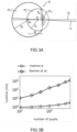
- a two sphere eye model as illustrated in figure 3A may be used.
- Figure 3A is a schematic view of an exemplary two-sphere model H for human eyes according to LeGrand. It approximates the eye geometry as consisting of two partial spheres.
- the larger partial sphere H 1 corresponds to the eyeball with center at position M and radius of curvature r e .
- eyeball radius of curvature r e 12 mm
- cornea radius r c 7.8 mm
- iris radius r s 6 mm.
- the pupil radius r typically varies in the physiologically plausible range of approximately 0.5-4.5 mm.
- FIG. 2 illustrates cameras 14, 24 and the human eyes H', H in the respective fields of view of the cameras 14, 24. Determining of (pupil circle) center lines L and eye intersecting lines D will be explained based on one side and camera first (monocularly), the calculations for the other side/camera being analogous. Thereafter, a binocular scenario will be explained.
- the cameras 14, 24 are typically near-eye cameras as explained above with regard to figures 1A to 1C .
- a Cartesian coordinate system y, z is additionally shown (x-axis perpendicular to paper plane). We will assume this to be a common 3D coordinate system into which all quantities originally calculated with respect to an individual camera's coordinate system can be or have been transformed.
- In gaze estimation estimating the optical axis O of the eye is a primary goal.
- In pupillometry estimating the actual size (radius) of the pupil in units of physical length (e.g. mm) is the primary goal.
- ⁇ and ⁇ are the spherical coordinates of the normalized vector pointing from M into the direction of the center of corneal curvature C.
- a first ellipse E 1 representing a border (outer contour) of the pupil H 3 at the first time t 1 is determined in a first image taken with the camera 24. This is typically achieved using image processing techniques.
- a camera model of the camera 24 is used to determine an orientation vector n 1 of the first circle C 1 and a first center line Li on which a center of the first circle C 1 is located, so that a projection of the first circle C 1 , in a direction parallel to the first center line L 1 , onto the image plane I p reproduces the first ellipse E 1 in the image.
- the same disambiguation procedure on pairs of un-projected circles as proposed in reference [1] (see figure 3 and corresponding description of [1]) may be used.
- a first eye intersecting line Di expected to intersect the center M of the eyeball at the first time t 1 may be determined as a line which is, in the direction of the orientation vector n 1 , parallel-shifted to the first center line Li by the expected distance R between the center M of the eyeball and the center P of the pupil.
- the circle selected by r*c 1 constitutes a 3D pupil candidate that is consistent with the observed pupil ellipse E 1 .
- n 1 is normalized to length equal 1, but vector ci is not, as explained above.
- Such eye intersecting lines D thus constitutes a method for generating data suitable for determining one or more parameters of at least one eye of a subject in a more simple and computationally more efficient and therefore faster way.
- a second ellipse E 2 representing the border of the pupil H 3 at a second time t 2 can be determined in a second image taken with the camera 24.
- the camera model may be used to determine an orientation vector n 2 of the second circle C 2 and a second center line L 2 on which a center of the second circle C 2 is located, so that a projection of the second circle C 2 , in a direction parallel to the second center line L 2 , onto the image plane I p of the camera reproduce the second ellipse E 2 in the image.
- the center M of the eyeball intersection is in practice typically taken in a least-squares sense.
- gaze directions gi, g 2 may be determined as being negative to the respective orientation vector n 1 , n 2 .
- the pupil radius r for each observation k can simply be obtained by scaling r*c k such that the resulting circle is tangent to the sphere centered at M and having radius R. Further, the respective optical axis may be determined as by (normalized) direction from P to the intersection point M.
- the number of pupils (image frames) that can be calculated with the monocular method explained above (method A) is, for the same computing hardware, typically at least one order of magnitude higher compared to the method of reference [1].
- a binocular method (method C)
- the same procedure for generating a 3D circle center line and a 3D eye intersecting line as explained for eyeball H with center M based on image data from camera 24 can be applied to a further eye H' with center M', based on image data from camera 14, at a second time (t' 1 ), substantially corresponding to the first time (t 1 ), yielding corresponding quantities for the further eye, which are denoted with a prime (') in the figure.
- the expected (constant) distance R' between the center of the eyeball M' and the center of the pupil P' of the further eye H' may be set equal to the corresponding value R of eye H, or may be an eye-specific value.
- a method further comprises using the first eye intersecting line Di and the further eye intersecting line D' 1 to determine expected coordinates of the center M of the eyeball H and of the center M' of the further eyeball H', such that each eyeball center lies on the respective eye intersecting line and the 3D distance between the eyeball centers corresponds to a predetermined value (IED, IPD), in particular a predetermined inter-eyeball distance IED.
- IED predetermined value
- IPD inter-eyeball distance
- the predetermined distance value (IED, IPD) between the center of the eyeball and the center of the further eyeball may be an average value, in particular a physiological constant or population average, or an individually measured value of the subject.
- the center of the eyeball and the center of the further eyeball can for example be found based on some assumption about the geometric setup of the device with respect to the eyes and head of the subject, for example that the interaural axis has to be perpendicular to some particular direction, like for example the z-axis of a device coordinate system such as shown in the example of figure 2 .
- a method further comprises determining the expected coordinates of the center M of the eyeball and of the center M' of the further eyeball, such that the radius r of the first circle in 3D and the radius r' of the further circle in 3D are substantially equal, thereby also determining said radius.
- the center of the 3D pupil P r*ci when r is chosen to be the actual pupil radius.
- pupils of different eyes are controlled by the same neural pathways and can not change size independently of each other.
- the pupil size of the left and of the right eye of for example a human is substantially equal at any instant in time.
- the optical axes (gaze vectors g k , g' k , which are antiparallel to n k , n' k respectively) and the (joint) pupil size of both eyes is provided in a glint-free scenario based on merely a single observation in time of two eyes of a subject.
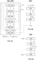
- Fig. 4A illustrates a flow chart of a method 1000 for generating data suitable for determining one or more parameters of an eye according to embodiments.
- the method 1000 may at least substantially correspond to the monocular method A explained above.
- an image I k of the user's eye may be taken by an eye camera of a device at a time t k .
- an ellipse E k representing a border of the eye's pupil at the time t k may be determined.
- a camera model describing the camera of the device is used to determine an orientation vector n k of a circle C k and a center line L k on which a center of the circle C k is located, so that a projection of the circle C k , in a direction parallel to the center line L k , onto an image plane of the camera reproduces the ellipse E k .
- the center line L k may be parallel-shifted by an expected distance R between the center of the eyeball and a center of the pupil in the direction of the orientation vector to determine an eye intersecting line D k which intersects a center M of the user's eyeball at the time t k in step 1400.
- Fig. 4A also illustrates a flow chart of a method 3000 for generating data suitable for determining one or more parameters of more than one eye according to embodiments.
- the method 3000 may at least substantially correspond to the binocular method C explained above with regard to figure 2 . Since the first steps of method 3000 are entirely analogous to the steps of method 1000, only based on image data of two eyes instead of one eye, corresponding reference numbers are used. Dashed quantities represent those of the second or further eye, as in figure 2 .
- an image I k of a user's eye and an image I' k of a user's further eye may be taken by one or more eye cameras of a device at a time t k ⁇ t' k .
- ellipses E k , E' k representing borders of the eyes' pupils at the time t k are determined.
- orientation vectors n k , n' k of circles C k , C' k , center lines L k , L' k and eye intersecting lines D k , D' k are determined as previously described.
- the iteration over several time steps (k++, right dashed arrow) is therefore not needed in method 3000.
- the procedure in method 3000 may optionally be repeated at a later time (t m > t 1 ) again (or even continuously), for example after movement of the camera(s) with respect to the eye(s) is detected or expected to have happened.
- other parameter(s) of the user's eyes such as gaze direction(s) g, g' and pupil size r, r' may be determined when the centres M, M' of the eyeballs are known. These other parameter(s) of the user's eyes may therefore also be determined for later times without recalculating the centers M, M' (to save computational time).
- any of the methods as described herein may use a stored correction function R corr taking into account corneal refraction to correct one or more parameters of the eye and/or the further eye of the subject.
- the correction function may be designed to take as input at least one parameter of one eye only, or may take as joint input parameters from several eyes.
- Applying the correction function R corr can be performed in a subsequent step 1600, 3600 at the end of any method as herein described, in particular the monocular and binocular methods previously described, indicated as method B in Fig.4A .
- the basic principle of generating the correction function is the same in all cases and is illustrated in Fig.4B as a flow chart of a method 2000.
- synthetic camera images SIi of several model eyeballs of an eye H with varying effective corneal refraction index n ref and a plurality of given values ⁇ X gt ⁇ of one or more parameters ⁇ X ⁇ of the model eyeball are determined using a model of the camera such as a pinhole model, assuming full perspective projection.
- a ray tracer may be used to generate the synthetic camera images.
- synthetic images may be ray traced at arbitrarily large image resolutions.
- the synthetic camera images SIi are used to determine expected values of the one or more parameters ⁇ X ex ⁇ .
- the expected values of the one or more parameters ⁇ X ex ⁇ are typically determined in analogy to any of the methods used to determine one or more parameters of an eye and/or a further eye of a subject as described herein, but based on the synthetic camera images SIi.
- n ref plays the role of an independent parameter to be able to account for variations in the effective refractive index of the cornea across subjects.
- mapping is typically achieved by a (multivariate) polynomial regression analysis.
- the correction function R corr may be used to correct the parameters determined by method A or by method C.
- subscripts 'gt' and 'ex' refer to the eyeball model parameters set for generating the synthetic camera images and the (expected) eyeball parameters determined from the synthetic camera images, respectively.
- the correction function may be designed such that it takes parameters from one eye only as input, or from more than one eye.
- ⁇ g, r, M, n ref ⁇ may stand for gaze direction, pupil radius, eyeball center and refraction index of one or of both eyes of a subject.
- R corr may be estimated by an empirical correction function in the following manner.
- a number of synthetic eye images are generated for each fixed value of n ref randomly drawn from [1.1, 1.4], with gaze angles ⁇ and ⁇ (forming g gt ) randomly chosen from a uniform distribution between -50° and 50°, and with pupil radii r gt randomly chosen from a uniform distribution between 0.5 mm and 4.5 mm.
- Pupil contours are extracted from all images, based on which eyeball parameters are then determined as explained below with regard to figure 4C .
- N maybe of the order of 10 3 or even 10 6 and the degree of the polynomial regression may for example be three, five or seven.
- Fig. 4C illustrates a flow chart of step 2200 of the method 2000 explained above with regard to figure 4B .
- a respective ellipse E i at least substantially representing a border of the pupil (of the model eye used for generating the synthetic camera images SI i ) is determined.
- the synthetic images may represent a monocular setup and thus comprise images of a single eye, or may represent a binocular setup and thus comprise images showing more than one eye or comprise pairs of images each showing a different eye of a synthetic user.
- respective orientation vectors n i of circles C i and center lines Li on which a center of the respective circle C i is located are determined in step 2230 using the camera model used for generating the synthetic camera images SIi, so that a projection of the circle C i , in a direction parallel to the first center line L i , onto the image plane of the camera model reproduces the respective ellipse E i .
- respective eye intersecting lines Di expected to intersect a center of the eyeball may be determined in step 2240 as lines which are, in the direction of the respective orientation vector n i , parallel-shifted to the respective center line Li by the expected distance R between the center of the eyeball and the center of the pupil (of the model eye).
- the eye intersecting lines Di may be used to determine the expected values of the pupil radii, gaze directions and eyeball centers (for example as least square intersecting point in a monocular setup or leveraging further constraints as explained previously in the context of binocular methods) as a parameters X ex .
- methods for generating data suitable for determining parameters of an eye are provided, which open the way to a fast non-iterative approach to the tasks of (refraction-aware) 3D gaze prediction and pupillometry based on pupil contours alone.
- these tasks are cast as a (least-squares) intersection of lines in a monocular, respectively an even simpler analytical geometry problem in a binocular setting.
- Systematic errors due to corneal refraction may be accounted for by means of empirical correction function(s).
Landscapes
- Engineering & Computer Science (AREA)
- Physics & Mathematics (AREA)
- General Physics & Mathematics (AREA)
- Health & Medical Sciences (AREA)
- Theoretical Computer Science (AREA)
- Human Computer Interaction (AREA)
- Ophthalmology & Optometry (AREA)
- General Health & Medical Sciences (AREA)
- Life Sciences & Earth Sciences (AREA)
- Optics & Photonics (AREA)
- Multimedia (AREA)
- General Engineering & Computer Science (AREA)
- Computer Vision & Pattern Recognition (AREA)
- Molecular Biology (AREA)
- Public Health (AREA)
- Veterinary Medicine (AREA)
- Animal Behavior & Ethology (AREA)
- Surgery (AREA)
- Medical Informatics (AREA)
- Heart & Thoracic Surgery (AREA)
- Biomedical Technology (AREA)
- Biophysics (AREA)
- Eye Examination Apparatus (AREA)
Claims (15)
- Computerimplementiertes Verfahren zur Erzeugung von Daten, die zur Bestimmung eines oder mehrerer Parameter eines Auges eines Subjekts geeignet sind, wobei das Auge einen Augapfel und eine, eine Pupille definierende Iris umfasst, wobei das Verfahren umfasst:- Empfangen von Bilddaten des Auges zu einem ersten Zeitpunkt (t1 ) von einer Kamera mit bekannten Kameraeigenschaften und die eine Bildebene definiert;- Bestimmen einer ersten Ellipse in den Bilddaten, wobei die erste Ellipse zumindest im Wesentlichen einen Rand der Pupille zu dem ersten Zeitpunkt (t1) darstellt;- Bestimmen eines 3D-Orientierungsvektors eines ersten Kreises in 3D und einer ersten Mittellinie, auf der sich ein Zentrum des ersten Kreises in 3D befindet, unter Verwendung der Kameraeigenschaften und der ersten Ellipse, so dass erwartet wird, dass eine Projektion des ersten Kreises in einer Richtung parallel zur ersten Mittellinie auf die Bildebene die erste Ellipse reproduziert; und- Bestimmen einer ersten Augenschnittlinie in 3D, von der erwartet wird, dass sie einen 3D-Mittelpunkt des Augapfels zum ersten Zeitpunkt (t1) als eine Linie schneidet, die in der Richtung des Orientierungsvektors parallel zur ersten Mittellinie um einen erwarteten Abstand (R) zwischen dem Mittelpunkt des Augapfels und einem Mittelpunkt der Pupille verschoben ist.
- Verfahren nach Anspruch 1, ferner umfassend:- Empfangen von Bilddaten eines weiteren Auges des Subjekts zu einem zweiten Zeitpunkt (t'1), der im Wesentlichen dem ersten Zeitpunkt (t1) entspricht, von einer Kamera mit bekannten Kameraeigenschaften und die eine Bildebene definiert, wobei das weitere Auge einen weiteren Augapfel und eine weitere Iris, die eine weitere Pupille definiert, umfasst;- Bestimmen einer weiteren Ellipse in den Bilddaten, wobei die weitere Ellipse zumindest im Wesentlichen den Rand der weiteren Pupille des weiteren Auges zu dem zweiten Zeitpunkt (t'1) darstellt;- Verwenden der Kameraeigenschaften und der weiteren Ellipse, um einen 3D-Orientierungsvektor eines weiteren Kreises in 3D und eine weitere Mittellinie zu bestimmen, auf der sich ein Zentrum des weiteren Kreises in 3D befindet, so dass erwartet wird, dass eine Projektion des weiteren Kreises in einer Richtung parallel zu der weiteren Mittellinie auf die Bildebene die weitere Ellipse reproduziert; und- Bestimmen einer weiteren Augenschnittlinie in 3D, von der erwartet wird, dass sie einen 3D-Mittelpunkt des weiteren Augapfels zum zweiten Zeitpunkt (t'1) schneidet, als eine Linie, die in der Richtung des 3D-Orientierungsvektors des weiteren Kreises um einen erwarteten Abstand (R') zwischen dem Mittelpunkt des weiteren Augapfels und einem Mittelpunkt der weiteren Pupille parallel zur weiteren Mittellinie verschoben ist,wobei die Bilddaten des Auges und des weiteren Auges typischerweise mit einer einzigen Kamera oder mit mehreren Kameras, deren relative Positionen bekannt sind, erzeugt werden.
- Verfahren nach Anspruch 2, ferner umfassend das Verwenden der ersten Augenschnittlinie und der weiteren Augenschnittlinie, um erwartete Koordinaten des Mittelpunkts des Augapfels und des Mittelpunkts des weiteren Augapfels zu bestimmen, so dass jeder Augapfelmittelpunkt auf der jeweiligen Augenschnittlinie liegt und der 3D-Abstand zwischen den Augapfelmittelpunkten einem vorbestimmten Wert (IED, IPD), insbesondere einem vorbestimmten Augapfelabstand, entspricht, wobei der vorbestimmte Wert (IED, IPD) zwischen der Mitte des Augapfels und der Mitte des weiteren Augapfels typischerweise ein Durchschnittswert, insbesondere eine physiologische Konstante oder ein Bevölkerungsdurchschnitt, oder ein individuell geschätzter oder gemessener Wert des Probanden ist.
- Verfahren nach Anspruch 3, ferner umfassend die Bestimmung der erwarteten Koordinaten des Mittelpunkts des Augapfels und des Mittelpunkts des weiteren Augapfels, so dass der Radius des ersten Kreises in 3D und der Radius des weiteren Kreises in 3D im Wesentlichen gleich sind, wodurch auch der Radius bestimmt wird, wobei die oder jede Kamera ein 3D-Koordinatensystem definiert, wobei zumindest die jeweiligen Orientierungsvektoren, Mittellinien und Augenschnittlinien in Bezug auf das 3D-Koordinatensystem der jeweiligen Kamera bestimmt und/oder über die bekannten relativen Kamerapositionen in ein gemeinsames 3D-Koordinatensystem transformiert werden, wobei der jeweilige 3D-Orientierungsvektor von der Kamera bzw. der jeweiligen Kamera weg zeigt, und/oder wobei der erwartete Abstand (R, R') zwischen der Mitte des Augapfels und der Mitte der Pupille ein Durchschnittswert ist, insbesondere eine physiologische Konstante oder ein Bevölkerungsdurchschnitt .
- Verfahren nach einem der vorhergehenden Ansprüche, ferner umfassend das Bestimmen einer erwarteten 3D-Blickrichtung (gk , k=1..n) des Auges und/oder des weiteren Auges als einen Vektor, der antiparallel zu dem jeweiligen 3D-Orientierungsvektor (nk , k=1..n) ist, für mindestens einen Zeitpunkt (tk , k=1..n).
- Verfahren nach einem der Ansprüche 3 bis 5, ferner umfassend die Verwendung der erwarteten Koordinaten des Mittelpunkts des Augapfels und/oder des Mittelpunkts des weiteren Augapfels, um für einen späteren Zeitpunkt (tm > t1) unter Verwendung späterer Bilddaten des Auges und/oder des weiteren Auges, die zu dem späteren Zeitpunkt (tm) erfasst wurden, mindestens eine erwartete optische Achse, eine erwartete Orientierung, eine erwartete Sehachse und eine erwartete Größe oder einen erwarteten Radius der Pupille des Auges und/oder des weiteren Auges zu bestimmen.
- Verfahren nach einem der vorhergehenden Ansprüche, wobei die jeweilige Mittellinie und/oder die jeweilige Augenschnittlinie unter Verwendung eines Modells der Kamera und/oder eines dreidimensionalen Augenmodells bestimmt wird, wobei das dreidimensionale Augenmodell ein Zwei-Sphären-Augenmodell ist, wobei die Kamera als Lochkamera modelliert wird, wobei das Modell der Kamera eine Brennweite, eine Verschiebung eines zentralen Bildpixels, einen Scherparameter und/oder einen Verzerrungsparameter umfasst, wobei das Verfahren ein Glitzern des Auges nicht berücksichtigt, um Daten zu erzeugen, die zur Bestimmung der Parameter des Auges geeignet sind, und/oder wobei das Verfahren glitzerfrei ist, und/oder wobei das Verfahren kein strukturiertes Licht und/oder keine spezielle Beleuchtung verwendet, um Parameter des Auges abzuleiten.
- Das Verfahren nach einem der vorangehenden Ansprüche umfasst ferner die Verwendung einer gespeicherten Korrekturfunktion (Rcorr), die eine Hornhautbrechung berücksichtigt, um den Parameter des Auges und/oder des weiteren Auges des Probanden zu korrigieren und/oder einen korrigierten Wert für die Mitte des Augapfels, die erwartete Blickrichtung, die erwartete optische Achse, die erwartete Orientierung, die erwartete Sichtachse und/oder die erwartete Größe oder den erwarteten Radius der Pupille des Auges und/oder des weiteren Auges des Subjektes zu bestimmen, wobei ein Bestimmen der gespeicherten Korrekturfunktion (Rcorr) für mindestens einen Parameter ({X}) mindestens eines Auges typischerweise Folgendes umfasst: -- Berechnen, unter Verwendung der bekannten Kameraeigenschaften, synthetischer Kamerabilder (SIi) mehrerer Modellaugäpfel mindestens eines Auges mit variierendem effektiven Hornhautbrechungsindex (nref), für eine Vielzahl gegebener Werte ({Xgt }) des mindestens einen Parameters der Modellaugäpfel;- Verwenden der synthetischen Kamerabilder (SIi ), um erwartete Werte des mindestens einen Parameters ({Xex}) zu bestimmen; und- Verwendung der erwarteten Werte des mindestens einen Parameters ({Xex}) und der gegebenen Werte des mindestens einen Parameters ({Xgt}) zur Bestimmung der Korrekturfunktion (Rcorr), die in Abhängigkeit vom effektiven Hornhaut-Brechungsindex (nref) die erwarteten Werte des mindestens einen Parameters ({Xex}) auf die jeweiligen gegebenen Werte des mindestens einen Parameters ({Xgt }) abbildet.
- Verfahren nach Anspruch 8, wobei die vorgegebenen Werte mindestens eine der folgenden Größen umfassen: vorgegebene Koordinaten der jeweiligen Mittelpunkte der Modellaugen, vorgegebene Radien einer Pupille der Modellaugen und vorgegebene Blickrichtungen der Modellaugen , wobei das Bestimmen der erwarteten Werte die Anwendung des Verfahrens nach einem der Ansprüche 1 bis 7 auf die synthetischen Kamerabilder (SI )i umfasst, wobei die Bestimmung der Korrekturfunktion (Rcorr) eine multivariate polynomiale Regressionsanalyse umfasst, und/oder wobei die Berechnung der synthetischen Kamerabilder (SIi) das Raytracing einer Anordnung eines Kameramodells umfasst, das die Kamera und die im Sichtfeld des Kameramodells angeordneten Modellaugäpfel beschreibt, und/oder wobei als Modell des Auges Zwei-Kugel-Augenmodelle verwendet werden.
- System, umfassend:eine Vorrichtung, die mindestens eine Kamera mit bekannten Kameraeigenschaften zum Erzeugen von Bilddaten umfasst, die mindestens ein Auge eines Subjekts enthalten, wobei die mindestens eine Kamera einen Sensor umfasst, der eine Bildebene (Ip) definiert, wobei das mindestens eine Auge einen Augapfel und eine Iris umfasst, die eine Pupille definiert; undeine Rechen- und Steuereinheit, die konfiguriert ist zum:- Empfangen von Bilddaten des mindestens einen Auges zu einem ersten Zeitpunkt (t1) von der mindestens einen Kamera;- Bestimmen einer ersten Ellipse in den Bilddaten, wobei die erste Ellipse zumindest im Wesentlichen einen Rand der Pupille zu dem ersten Zeitpunkt (t1) darstellt;- Verwenden der Kameraeigenschaften und der ersten Ellipse, um einen 3D-Orientierungsvektor eines ersten Kreises in 3D und eine erste Mittellinie zu bestimmen, auf der sich ein Zentrum des ersten Kreises in 3D befindet, so dass erwartet wird, dass eine Projektion des ersten Kreises in einer Richtung parallel zu der ersten Mittellinie auf die Bildebene die erste Ellipse reproduziert; und- Bestimmen einer ersten Augenschnittlinie in 3D, von der erwartet wird, dass sie einen 3D-Mittelpunkt des Augapfels zum ersten Zeitpunkt (t1) schneidet, als eine Linie, die in Richtung des Orientierungsvektors um einen erwarteten Abstand (R) zwischen dem Mittelpunkt des Augapfels und einem Mittelpunkt der Pupille parallel zur ersten Mittellinie verschoben ist.
- System nach Anspruch 10, wobei die Rechen- und Steuereinheit konfiguriert ist zum:- Empfangen von Bilddaten eines weiteren Auges des Subjekts zu einem zweiten Zeitpunkt (t'1), der im Wesentlichen dem ersten Zeitpunkt (t1) entspricht, von einer Kamera mit bekannten Kameraeigenschaften und die eine Bildebene definiert, wobei das weitere Auge einen weiteren Augapfel und eine weitere Iris umfasst, die eine weitere Pupille definiert;- Bestimmen einer weiteren Ellipse in den Bilddaten, wobei die weitere Ellipse zumindest im Wesentlichen den Rand der weiteren Pupille des weiteren Auges zum zweiten Zeitpunkt (t'1) darstellt;- Verwenden der Kameraeigenschaften und der weiteren Ellipse, um einen 3D-Orientierungsvektor eines weiteren Kreises in 3D und eine weitere Mittellinie zu bestimmen, auf der sich ein Zentrum des weiteren Kreises in 3D befindet, so dass eine Projektion des weiteren Kreises in einer Richtung parallel zu der weiteren Mittellinie auf die Bildebene die weitere Ellipse wiedergeben soll;- Bestimmen einer weiteren Augenschnittlinie in 3D, von der erwartet wird, dass sie einen 3D-Mittelpunkt des weiteren Augapfels zum zweiten Zeitpunkt (t'1 ) schneidet, als eine Linie, die in der Richtung des 3D-Orientierungsvektors des weiteren Kreises parallel zur weiteren Mittellinie um einen erwarteten Abstand (R') zwischen dem Mittelpunkt des weiteren Augapfels und einem Mittelpunkt der weiteren Pupille verschoben ist; und- Verwendung der ersten Augenschnittlinie und der weiteren Augenschnittlinie zur Bestimmung erwarteter Koordinaten des Mittelpunkts des Augapfels und des Mittelpunkts des weiteren Augapfels, so dass jeder Augapfelmittelpunkt auf der jeweiligen Augenschnittlinie liegt und der 3D-Abstand zwischen den Augapfelmittelpunkten einem vorbestimmten Wert (IED, IPD), insbesondere einem vorbestimmten Augenabstand, entspricht; und/oderwobei die Rechen- und Steuereinheit zur Durchführung des Verfahrens nach einem der Ansprüche 1 bis 9 ausgebildet ist.
- System nach einem der Ansprüche 10 bis 11, wobei die Rechen- und Steuereinheit so konfiguriert ist, dass sie die Bilddaten des Auges und die Bilddaten des weiteren Auges von einer einzigen Kamera oder von verschiedenen Kameras empfängt, deren relative Posen bekannt sind, und ferner so konfiguriert ist, dass sie zumindest die jeweiligen Orientierungsvektoren, Mittellinien und Augenschnittlinien in Bezug auf das 3D-Koordinatensystem der jeweiligen Kamera bestimmt, und/oder über die bekannten relativen Kamerapositionen in ein gemeinsames 3D-Koordinatensystem zu transformieren, wobei die Vorrichtung eine am Kopf zu tragende Vorrichtung oder eine entfernte Eye-Tracking-Vorrichtung ist, wobei der erwartete Abstand (R') zwischen dem Mittelpunkt des weiteren Augapfels und dem Mittelpunkt der weiteren Pupille zumindest im Wesentlichen gleich dem erwarteten Abstand (R) zwischen dem Mittelpunkt des Augapfels und dem Mittelpunkt der Pupille ist, und/oder wobei der erwartete Abstand (R, R') ein Durchschnittswert, insbesondere eine physiologische Konstante oder ein Populationsdurchschnitt ist.
- System nach einem der Ansprüche 10 bis 12, wobei die Rechen- und Steuereinheit so konfiguriert ist, dass sie eine gespeicherte Korrekturfunktion verwendet, die eine Hornhautrefraktion berücksichtigt, um einen korrigierten Wert für den mindestens einen Parameter mindestens eines Auges eines Subjekts zu bestimmen, insbesondere für mindestens eine der folgenden Größen: die Mitte des Augapfels, die erwartete Blickrichtung des Auges, die erwartete optische Achse des Auges, die erwartete Ausrichtung des Auges, die erwartete Sehachse des Auges und die erwartete Größe oder den erwarteten Radius der Pupille, insbesondere eine gespeicherte Korrekturfunktion, die nach dem Verfahren eines der Ansprüche 8 bis 9 bestimmt wird.
- System nach einem der Ansprüche 10 bis 13, wobei eine Position und/oder Ausrichtung der jeweiligen Kamera(s) in Bezug auf einen Rahmen der Vorrichtung unveränderlich fest oder einstellbar und/oder fixierbar ist, insbesondere derart, dass die relativen Positionen der Kameras bauartbedingt bekannt sind oder nach einer Einstellung gemessen werden können, und/oder wobei die Rechen- und Steuereinheit zumindest teilweise in die Vorrichtung integriert ist und/oder zumindest teilweise von einem Begleitgerät des Systems, insbesondere einem mobilen Begleitgerät, bereitgestellt wird.
- Computerprogrammprodukt und/oder computerlesbares Speichermedium mit Befehlen, die bei Ausführung durch einen oder mehrere Prozessoren eines Systems, insbesondere des Systems nach einem der Ansprüche 10 bis 14, das System veranlassen, die Schritte des Verfahrens nach einem der Ansprüche 1 bis 9 auszuführen.
Applications Claiming Priority (2)
| Application Number | Priority Date | Filing Date | Title |
|---|---|---|---|
| PCT/EP2019/064656 WO2020244752A1 (en) | 2019-06-05 | 2019-06-05 | Devices, systems and methods for predicting gaze-related parameters |
| PCT/EP2020/064593 WO2020244971A1 (en) | 2019-06-05 | 2020-05-26 | Methods, devices and systems for determining eye parameters |
Publications (3)
| Publication Number | Publication Date |
|---|---|
| EP3979897A1 EP3979897A1 (de) | 2022-04-13 |
| EP3979897B1 true EP3979897B1 (de) | 2025-02-12 |
| EP3979897C0 EP3979897C0 (de) | 2025-02-12 |
Family
ID=66776353
Family Applications (3)
| Application Number | Title | Priority Date | Filing Date |
|---|---|---|---|
| EP19728979.6A Active EP3979896B1 (de) | 2019-06-05 | 2019-06-05 | Vorrichtungen, systeme und verfahren zur vorhersage von blickbezogenen parametern |
| EP20728489.4A Active EP3979897B1 (de) | 2019-06-05 | 2020-05-26 | Verfahren, vorrichtungen und systeme zur bestimmung von augenparametern |
| EP21710513.9A Active EP4157065B1 (de) | 2019-06-05 | 2021-03-12 | Verfahren, vorrichtungen und systeme zur bestimmung von augenzustandsvariablen |
Family Applications Before (1)
| Application Number | Title | Priority Date | Filing Date |
|---|---|---|---|
| EP19728979.6A Active EP3979896B1 (de) | 2019-06-05 | 2019-06-05 | Vorrichtungen, systeme und verfahren zur vorhersage von blickbezogenen parametern |
Family Applications After (1)
| Application Number | Title | Priority Date | Filing Date |
|---|---|---|---|
| EP21710513.9A Active EP4157065B1 (de) | 2019-06-05 | 2021-03-12 | Verfahren, vorrichtungen und systeme zur bestimmung von augenzustandsvariablen |
Country Status (3)
| Country | Link |
|---|---|
| US (3) | US11676422B2 (de) |
| EP (3) | EP3979896B1 (de) |
| WO (3) | WO2020244752A1 (de) |
Families Citing this family (8)
| Publication number | Priority date | Publication date | Assignee | Title |
|---|---|---|---|---|
| EP3979896B1 (de) | 2019-06-05 | 2024-11-13 | Pupil Labs GmbH | Vorrichtungen, systeme und verfahren zur vorhersage von blickbezogenen parametern |
| GB2594966B (en) * | 2020-05-13 | 2024-07-31 | Sony Interactive Entertainment Inc | Gaze tracking apparatus and systems |
| EP4215976A4 (de) * | 2021-01-18 | 2024-05-01 | Samsung Electronics Co., Ltd. | Tragbare elektronische vorrichtung mit miniaturkamera |
| US11861805B2 (en) | 2021-09-22 | 2024-01-02 | Sony Group Corporation | Eyeball positioning for 3D head modeling |
| JP2023063680A (ja) * | 2021-10-25 | 2023-05-10 | キヤノン株式会社 | 視線入力装置および画像表示装置 |
| EP4303652B1 (de) | 2022-07-07 | 2025-08-20 | Pupil Labs GmbH | Kameramodul, am kopf tragbare augenverfolgungsvorrichtung und verfahren zur herstellung eines kameramoduls |
| CN120380439A (zh) | 2022-12-21 | 2025-07-25 | 学生实验室有限公司 | 用于训练眼睛状态预测器的系统和方法 |
| CN118778269B (zh) * | 2024-09-09 | 2024-11-19 | 中国兵器装备集团自动化研究所有限公司 | 一种无人机可穿戴操控装置及无人机系统 |
Family Cites Families (193)
| Publication number | Priority date | Publication date | Assignee | Title |
|---|---|---|---|---|
| US4852988A (en) | 1988-09-12 | 1989-08-01 | Applied Science Laboratories | Visor and camera providing a parallax-free field-of-view image for a head-mounted eye movement measurement system |
| US6351273B1 (en) | 1997-04-30 | 2002-02-26 | Jerome H. Lemelson | System and methods for controlling automatic scrolling of information on a display or screen |
| WO1999005988A2 (en) | 1997-07-30 | 1999-02-11 | Applied Science Laboratories | An eye tracker using an off-axis, ring illumination source |
| EP1027627B1 (de) | 1997-10-30 | 2009-02-11 | MYVU Corporation | Schnittstellensystem für brillen |
| AU1165799A (en) | 1997-11-17 | 1999-06-07 | British Telecommunications Public Limited Company | User interface |
| DE19807902A1 (de) | 1998-02-25 | 1999-09-09 | Genesys Elektronik Gmbh | Verfahren und Einrichtung zur Ermittlung der Gleichgewichtskontrolle eines Lebewesens |
| WO2002031581A1 (de) | 2000-10-07 | 2002-04-18 | Physoptics Opto-Electronic Gmbh | Vorrichtung und verfahren zur bestimmung der orientierung eines auges |
| US6771423B2 (en) | 2001-05-07 | 2004-08-03 | Richard Geist | Head-mounted virtual display apparatus with a near-eye light deflecting element in the peripheral field of view |
| US6943754B2 (en) | 2002-09-27 | 2005-09-13 | The Boeing Company | Gaze tracking system, eye-tracking assembly and an associated method of calibration |
| US7306337B2 (en) | 2003-03-06 | 2007-12-11 | Rensselaer Polytechnic Institute | Calibration-free gaze tracking under natural head movement |
| WO2005009466A1 (en) | 2003-07-24 | 2005-02-03 | Universita' Degli Studi Di Perugia | Methods and compositions for increasing the efficiency of therapeutic antibodies using alloreactive natural killer cells |
| US6889412B2 (en) | 2003-08-12 | 2005-05-10 | Yiling Xie | Method for producing eyewear frame support arms without welding |
| GB2412431B (en) | 2004-03-25 | 2007-11-07 | Hewlett Packard Development Co | Self-calibration for an eye tracker |
| AU2005229076B2 (en) | 2004-04-01 | 2011-09-15 | Google Llc | Biosensors, communicators, and controllers monitoring eye movement and methods for using them |
| US7686451B2 (en) | 2005-04-04 | 2010-03-30 | Lc Technologies, Inc. | Explicit raytracing for gimbal-based gazepoint trackers |
| DE202005009131U1 (de) | 2005-06-10 | 2005-10-20 | Uvex Arbeitsschutz Gmbh | Scharnierlose Brille, insbesondere Arbeitsschutzbrille |
| NZ564852A (en) | 2005-08-11 | 2010-01-29 | Sleep Diagnostics Pty Ltd | Alertness sensing spectacles having an eyelid sensor to detect eyelid movement |
| WO2007102053A2 (en) | 2005-09-16 | 2007-09-13 | Imotions-Emotion Technology Aps | System and method for determining human emotion by analyzing eye properties |
| US20090190026A1 (en) | 2006-01-11 | 2009-07-30 | Leo Chen | Pair of Spectacles with Miniature Camera |
| ITRM20070526A1 (it) | 2007-10-05 | 2009-04-06 | Univ Roma | Apparato di acquisizione ed elaborazione delle informazioni relative ad attivita oculari umane |
| JP5055166B2 (ja) | 2008-02-29 | 2012-10-24 | キヤノン株式会社 | 眼の開閉度判定装置、方法及びプログラム、撮像装置 |
| US7736000B2 (en) | 2008-08-27 | 2010-06-15 | Locarna Systems, Inc. | Method and apparatus for tracking eye movement |
| WO2010071928A1 (en) | 2008-12-22 | 2010-07-01 | Seeing Machines Limited | Automatic calibration of a gaze direction algorithm from user behaviour |
| EP2309307B1 (de) | 2009-10-08 | 2020-12-09 | Tobii Technology AB | Augenverfolgung mithilfe einer grafischen Prozessoreinheit |
| DE102009049849B4 (de) | 2009-10-19 | 2020-09-24 | Apple Inc. | Verfahren zur Bestimmung der Pose einer Kamera, Verfahren zur Erkennung eines Objekts einer realen Umgebung und Verfahren zur Erstellung eines Datenmodells |
| US8890946B2 (en) | 2010-03-01 | 2014-11-18 | Eyefluence, Inc. | Systems and methods for spatially controlled scene illumination |
| DE102010018562A1 (de) | 2010-04-23 | 2011-10-27 | Leibniz-Institut für Arbeitsforschung an der TU Dortmund | Verfahren und Vorrichtung zur Eichung von Eye-tracking-Systemen |
| WO2011144932A1 (en) | 2010-05-20 | 2011-11-24 | Bae Systems Plc | Eye monitor for monitoring the size of a pupil |
| EP2573650A1 (de) | 2010-05-20 | 2013-03-27 | Nec Corporation | Tragbares informationsverarbeitungsendgerät |
| US9557812B2 (en) | 2010-07-23 | 2017-01-31 | Gregory A. Maltz | Eye gaze user interface and calibration method |
| US9977496B2 (en) | 2010-07-23 | 2018-05-22 | Telepatheye Inc. | Eye-wearable device user interface and augmented reality method |
| JP2012038106A (ja) | 2010-08-06 | 2012-02-23 | Canon Inc | 情報処理装置、情報処理方法、およびプログラム |
| TWM401786U (en) | 2010-09-01 | 2011-04-11 | Southern Taiwan Univ | Eyeglasses capable of recognizing eyeball movement messages |
| WO2012052061A1 (en) | 2010-10-22 | 2012-04-26 | Institut für Rundfunktechnik GmbH | Method and system for calibrating a gaze detector system |
| US9185352B1 (en) | 2010-12-22 | 2015-11-10 | Thomas Jacques | Mobile eye tracking system |
| US20120212593A1 (en) | 2011-02-17 | 2012-08-23 | Orcam Technologies Ltd. | User wearable visual assistance system |
| EP2499960B1 (de) | 2011-03-18 | 2015-04-22 | SensoMotoric Instruments Gesellschaft für innovative Sensorik mbH | Verfahren zur Bestimmung von mindestens einem Parameter aus zwei Augen durch Einstellen der Datenraten und optische Messvorrichtung |
| US9033502B2 (en) | 2011-03-18 | 2015-05-19 | Sensomotoric Instruments Gesellschaft Fur Innovative Sensorik Mbh | Optical measuring device and method for capturing at least one parameter of at least one eye wherein an illumination characteristic is adjustable |
| US8594374B1 (en) | 2011-03-30 | 2013-11-26 | Amazon Technologies, Inc. | Secure device unlock with gaze calibration |
| US8510166B2 (en) | 2011-05-11 | 2013-08-13 | Google Inc. | Gaze tracking system |
| US8885877B2 (en) | 2011-05-20 | 2014-11-11 | Eyefluence, Inc. | Systems and methods for identifying gaze tracking scene reference locations |
| US8911087B2 (en) | 2011-05-20 | 2014-12-16 | Eyefluence, Inc. | Systems and methods for measuring reactions of head, eyes, eyelids and pupils |
| US9134127B2 (en) | 2011-06-24 | 2015-09-15 | Trimble Navigation Limited | Determining tilt angle and tilt direction using image processing |
| CA2750287C (en) | 2011-08-29 | 2012-07-03 | Microsoft Corporation | Gaze detection in a see-through, near-eye, mixed reality display |
| US8854282B1 (en) * | 2011-09-06 | 2014-10-07 | Google Inc. | Measurement method |
| US8879801B2 (en) | 2011-10-03 | 2014-11-04 | Qualcomm Incorporated | Image-based head position tracking method and system |
| US8723798B2 (en) | 2011-10-21 | 2014-05-13 | Matthew T. Vernacchia | Systems and methods for obtaining user command from gaze direction |
| WO2013059940A1 (en) | 2011-10-27 | 2013-05-02 | Tandemlaunch Technologies Inc. | System and method for calibrating eye gaze data |
| US8752963B2 (en) | 2011-11-04 | 2014-06-17 | Microsoft Corporation | See-through display brightness control |
| US8929589B2 (en) | 2011-11-07 | 2015-01-06 | Eyefluence, Inc. | Systems and methods for high-resolution gaze tracking |
| US9311883B2 (en) | 2011-11-11 | 2016-04-12 | Microsoft Technology Licensing, Llc | Recalibration of a flexible mixed reality device |
| EP2795888B1 (de) | 2011-12-19 | 2015-09-23 | Dolby Laboratories Licensing Corporation | Auf einem kopf montierte anzeige |
| US9001030B2 (en) | 2012-02-15 | 2015-04-07 | Google Inc. | Heads up display |
| US9001005B2 (en) | 2012-02-29 | 2015-04-07 | Recon Instruments Inc. | Modular heads-up display systems |
| US9004687B2 (en) * | 2012-05-18 | 2015-04-14 | Sync-Think, Inc. | Eye tracking headset and system for neuropsychological testing including the detection of brain damage |
| US9001427B2 (en) | 2012-05-30 | 2015-04-07 | Microsoft Technology Licensing, Llc | Customized head-mounted display device |
| US9146397B2 (en) | 2012-05-30 | 2015-09-29 | Microsoft Technology Licensing, Llc | Customized see-through, electronic display device |
| TWI471808B (zh) | 2012-07-20 | 2015-02-01 | Pixart Imaging Inc | 瞳孔偵測裝置 |
| US8931893B2 (en) | 2012-08-10 | 2015-01-13 | Prohero Group Co., Ltd. | Multi-purpose eyeglasses |
| US9164580B2 (en) | 2012-08-24 | 2015-10-20 | Microsoft Technology Licensing, Llc | Calibration of eye tracking system |
| JP5887026B2 (ja) | 2012-09-03 | 2016-03-16 | ゼンソモトリック インストゥルメンツ ゲゼルシャフト ヒューア イノベイティブ ゼンソリック エムベーハーSENSOMOTORIC INSTRUMENTS Gesellschaft fur innovative Sensorik mbH | ヘッドマウントシステム及びヘッドマウントシステムを用いてディジタル画像のストリームを計算しレンダリングする方法 |
| US8836768B1 (en) | 2012-09-04 | 2014-09-16 | Aquifi, Inc. | Method and system enabling natural user interface gestures with user wearable glasses |
| US9207760B1 (en) | 2012-09-28 | 2015-12-08 | Google Inc. | Input detection |
| CN102930252B (zh) | 2012-10-26 | 2016-05-11 | 广东百泰科技有限公司 | 一种基于神经网络头部运动补偿的视线跟踪方法 |
| US20140152558A1 (en) | 2012-11-30 | 2014-06-05 | Tom Salter | Direct hologram manipulation using imu |
| EP2929413B1 (de) | 2012-12-06 | 2020-06-03 | Google LLC | Tragbare augenverfolgungsvorrichtungen und verfahren zur verwendung |
| US20140191927A1 (en) | 2013-01-09 | 2014-07-10 | Lg Electronics Inc. | Head mount display device providing eye gaze calibration and control method thereof |
| KR20140090552A (ko) | 2013-01-09 | 2014-07-17 | 엘지전자 주식회사 | 시선 캘리브레이션을 제공하는 헤드 마운트 디스플레이 및 그 제어 방법 |
| US9788714B2 (en) | 2014-07-08 | 2017-10-17 | Iarmourholdings, Inc. | Systems and methods using virtual reality or augmented reality environments for the measurement and/or improvement of human vestibulo-ocular performance |
| WO2014125380A2 (en) | 2013-02-14 | 2014-08-21 | The Eye Tribe Aps | Systems and methods of eye tracking calibration |
| EP2962251A1 (de) | 2013-02-27 | 2016-01-06 | Thomson Licensing | Verfahren und vorrichtung für kalibrierungsfreie blickschätzung |
| US20140247210A1 (en) | 2013-03-01 | 2014-09-04 | Tobii Technology Ab | Zonal gaze driven interaction |
| US9335547B2 (en) | 2013-03-25 | 2016-05-10 | Seiko Epson Corporation | Head-mounted display device and method of controlling head-mounted display device |
| WO2014186620A1 (en) | 2013-05-15 | 2014-11-20 | The Johns Hopkins University | Eye tracking and gaze fixation detection systems, components and methods using polarized light |
| JP6020923B2 (ja) * | 2013-05-21 | 2016-11-02 | パナソニックIpマネジメント株式会社 | 焦点可変レンズを有するビューア、および映像表示システム |
| US9801539B2 (en) | 2013-05-23 | 2017-10-31 | Stiftung Caesar—Center Of Advanced European Studies And Research | Ocular Videography System |
| WO2014192001A2 (en) | 2013-05-30 | 2014-12-04 | Umoove Services Ltd. | Smooth pursuit gaze tracking |
| TWI507762B (zh) | 2013-05-31 | 2015-11-11 | Pixart Imaging Inc | 眼球追跡裝置及其光學組件 |
| US9189095B2 (en) | 2013-06-06 | 2015-11-17 | Microsoft Technology Licensing, Llc | Calibrating eye tracking system by touch input |
| CN103356163B (zh) | 2013-07-08 | 2016-03-30 | 东北电力大学 | 基于视频图像和人工神经网络的凝视点测量装置及其方法 |
| AT513987B1 (de) | 2013-08-23 | 2014-09-15 | Ernst Dipl Ing Dr Pfleger | Brille und Verfahren zur Bestimmung von Pupillenmittelpunkten beider Augen eines Menschen |
| EP3041400A1 (de) | 2013-09-03 | 2016-07-13 | Tobii AB | Tragbare augenverfolgungsvorrichtung |
| US10310597B2 (en) | 2013-09-03 | 2019-06-04 | Tobii Ab | Portable eye tracking device |
| US10007336B2 (en) | 2013-09-10 | 2018-06-26 | The Board Of Regents Of The University Of Texas System | Apparatus, system, and method for mobile, low-cost headset for 3D point of gaze estimation |
| US9480397B2 (en) | 2013-09-24 | 2016-11-01 | Sony Interactive Entertainment Inc. | Gaze tracking variations using visible lights or dots |
| KR102088020B1 (ko) | 2013-09-26 | 2020-03-11 | 엘지전자 주식회사 | 헤드 마운트 디스플레이 및 제어 방법 |
| WO2015051834A1 (en) | 2013-10-09 | 2015-04-16 | Metaio Gmbh | Method and system for determining a pose of a camera |
| FR3011952B1 (fr) | 2013-10-14 | 2017-01-27 | Suricog | Procede d'interaction par le regard et dispositif associe |
| US10372204B2 (en) | 2013-10-30 | 2019-08-06 | Technology Against Als | Communication and control system and method |
| WO2015072202A1 (ja) | 2013-11-18 | 2015-05-21 | ソニー株式会社 | 瞳孔径に基づく眼の疲労検出のための情報処理装置、方法、およびプログラム |
| EP2886041A1 (de) | 2013-12-17 | 2015-06-24 | ESSILOR INTERNATIONAL (Compagnie Générale d'Optique) | Verfahren zur Kalibrierung einer am Kopf montierten Augenverfolgungsvorrichtung |
| US20170123491A1 (en) | 2014-03-17 | 2017-05-04 | Itu Business Development A/S | Computer-implemented gaze interaction method and apparatus |
| US9361519B2 (en) * | 2014-03-28 | 2016-06-07 | Intel Corporation | Computational array camera with dynamic illumination for eye tracking |
| DE102014206623A1 (de) | 2014-04-07 | 2015-10-08 | Bayerische Motoren Werke Aktiengesellschaft | Lokalisierung eines Head-mounted Displays (HMD) im Fahrzeug |
| RU2551799C1 (ru) | 2014-04-09 | 2015-05-27 | Алексей Леонидович УШАКОВ | Составное носимое устройство электросвязи |
| WO2015154882A1 (en) | 2014-04-11 | 2015-10-15 | The Eye Tribe Aps | Systems and methods of eye tracking calibration |
| US20150302585A1 (en) | 2014-04-22 | 2015-10-22 | Lenovo (Singapore) Pte. Ltd. | Automatic gaze calibration |
| US9672416B2 (en) | 2014-04-29 | 2017-06-06 | Microsoft Technology Licensing, Llc | Facial expression tracking |
| JP6550460B2 (ja) | 2014-05-09 | 2019-07-24 | グーグル エルエルシー | 眼信号を識別するためのシステムおよび方法、ならびに連続バイオメトリック認証 |
| US9727136B2 (en) | 2014-05-19 | 2017-08-08 | Microsoft Technology Licensing, Llc | Gaze detection calibration |
| US9961307B1 (en) | 2014-06-30 | 2018-05-01 | Lee S. Weinblatt | Eyeglass recorder with multiple scene cameras and saccadic motion detection |
| US9515420B2 (en) | 2014-07-21 | 2016-12-06 | Daniel J Daoura | Quick connect interface |
| US9965030B2 (en) | 2014-07-31 | 2018-05-08 | Samsung Electronics Co., Ltd. | Wearable glasses and method of displaying image via the wearable glasses |
| US9851567B2 (en) | 2014-08-13 | 2017-12-26 | Google Llc | Interchangeable eyewear/head-mounted device assembly with quick release mechanism |
| US10682038B1 (en) | 2014-09-19 | 2020-06-16 | Colorado School Of Mines | Autonomous robotic laparoscope based on eye tracking |
| US9253442B1 (en) | 2014-10-07 | 2016-02-02 | Sap Se | Holopresence system |
| US9936195B2 (en) | 2014-11-06 | 2018-04-03 | Intel Corporation | Calibration for eye tracking systems |
| US10016131B2 (en) | 2014-11-14 | 2018-07-10 | Sensomotoric Instruments Gesellschaft Fur Innovative Sensorik Mbh | Eye tracking system and method to detect the dominant eye |
| US9851791B2 (en) | 2014-11-14 | 2017-12-26 | Facebook, Inc. | Dynamic eye tracking calibration |
| US20170351326A1 (en) | 2014-11-18 | 2017-12-07 | Koninklijke Philips N.V. | Eye training system and computer program product |
| JP2016106668A (ja) | 2014-12-02 | 2016-06-20 | ソニー株式会社 | 情報処理装置、情報処理方法、およびプログラム |
| US10213105B2 (en) | 2014-12-11 | 2019-02-26 | AdHawk Microsystems | Eye-tracking system and method therefor |
| US10317672B2 (en) | 2014-12-11 | 2019-06-11 | AdHawk Microsystems | Eye-tracking system and method therefor |
| CN107106007B (zh) | 2014-12-16 | 2020-10-02 | 皇家飞利浦有限公司 | 具有校准改进、准确度补偿和注视局部化平滑的注视跟踪系统 |
| KR102469507B1 (ko) | 2014-12-17 | 2022-11-22 | 소니그룹주식회사 | 정보 처리 장치, 정보 처리 방법 및 프로그램 |
| US10073516B2 (en) | 2014-12-29 | 2018-09-11 | Sony Interactive Entertainment Inc. | Methods and systems for user interaction within virtual reality scene using head mounted display |
| US10048749B2 (en) | 2015-01-09 | 2018-08-14 | Microsoft Technology Licensing, Llc | Gaze detection offset for gaze tracking models |
| US9864430B2 (en) | 2015-01-09 | 2018-01-09 | Microsoft Technology Licensing, Llc | Gaze tracking via eye gaze model |
| US9341867B1 (en) | 2015-01-16 | 2016-05-17 | James Chang Ho Kim | Methods of designing and fabricating custom-fit eyeglasses using a 3D printer |
| EP3047883B1 (de) | 2015-01-21 | 2017-09-13 | Oculus VR, LLC | Komprimierbare augenmuschelanordnung in einer brille für virtuelle realität |
| US9851091B2 (en) | 2015-02-18 | 2017-12-26 | Lg Electronics Inc. | Head mounted display |
| US11023038B2 (en) | 2015-03-05 | 2021-06-01 | Sony Corporation | Line of sight detection adjustment unit and control method |
| US10416764B2 (en) | 2015-03-13 | 2019-09-17 | Apple Inc. | Method for operating an eye tracking device for multi-user eye tracking and eye tracking device |
| CN112667069A (zh) | 2015-03-13 | 2021-04-16 | 苹果公司 | 用于自动识别眼睛追踪设备的至少一个用户的方法以及眼睛追踪设备 |
| US9451166B1 (en) | 2015-03-24 | 2016-09-20 | Raytheon Company | System and method for imaging device motion compensation |
| US10045737B2 (en) | 2015-06-14 | 2018-08-14 | Facense Ltd. | Clip-on device with inward-facing cameras |
| CN107533375B (zh) | 2015-06-29 | 2024-06-18 | 依视路国际公司 | 场景图像分析模块 |
| EP3112922A1 (de) | 2015-06-30 | 2017-01-04 | Thomson Licensing | Blickverfolgungsvorrichtung und kopfmontierte vorrichtung mit eingebetteter blickverfolgungsvorrichtung |
| CN104951084B (zh) | 2015-07-30 | 2017-12-29 | 京东方科技集团股份有限公司 | 视线追踪方法及装置 |
| US20170038607A1 (en) | 2015-08-04 | 2017-02-09 | Rafael Camara | Enhanced-reality electronic device for low-vision pathologies, and implant procedure |
| US9501683B1 (en) | 2015-08-05 | 2016-11-22 | Datalogic Automation, Inc. | Multi-frame super-resolution barcode imager |
| WO2017025486A1 (en) | 2015-08-07 | 2017-02-16 | SensoMotoric Instruments Gesellschaft für innovative Sensorik mbH | Method and system to control a workflow and method and system for providing a set of task-specific control parameters |
| US9829976B2 (en) | 2015-08-07 | 2017-11-28 | Tobii Ab | Gaze direction mapping |
| EP3135464B1 (de) | 2015-08-27 | 2018-10-03 | Okia Optical Company Limited | Verfahren zur herstellung von brillen durch 3d-druck |
| US10016130B2 (en) | 2015-09-04 | 2018-07-10 | University Of Massachusetts | Eye tracker system and methods for detecting eye parameters |
| FR3041230B1 (fr) | 2015-09-18 | 2022-04-15 | Suricog | Procede de determination de parametres anatomiques |
| US10467470B2 (en) | 2015-09-24 | 2019-11-05 | Tobii Ab | Eye-tracking enabled wearable devices |
| US10173324B2 (en) | 2015-11-16 | 2019-01-08 | Abb Schweiz Ag | Facilitating robot positioning |
| EP3384468A4 (de) | 2015-12-04 | 2019-01-30 | Magic Leap, Inc. | Relokalisierungssysteme und -verfahren |
| US10217261B2 (en) | 2016-02-18 | 2019-02-26 | Pinscreen, Inc. | Deep learning-based facial animation for head-mounted display |
| CN109074513B (zh) | 2016-03-03 | 2020-02-18 | 谷歌有限责任公司 | 用于机器人抓握的深度机器学习方法和装置 |
| CN105676456A (zh) | 2016-04-06 | 2016-06-15 | 众景视界(北京)科技有限公司 | 模块化头戴式电子设备 |
| US10423830B2 (en) | 2016-04-22 | 2019-09-24 | Intel Corporation | Eye contact correction in real time using neural network based machine learning |
| US9854968B2 (en) | 2016-05-20 | 2018-01-02 | International Business Machines Corporation | Behind-eye monitoring using natural reflection of lenses |
| EP3252566B1 (de) | 2016-06-03 | 2021-01-06 | Facebook Technologies, LLC | Gesichts- und augenverfolgung sowie gesichtsanimation mit gesichtssensoren in einer kopfmontierten anzeige |
| DE102016210288A1 (de) | 2016-06-10 | 2017-12-14 | Volkswagen Aktiengesellschaft | Bedienvorrichtung mit Eyetrackereinheit und Verfahren zum Kalibrieren einer Eyetrackereinheit einer Bedienvorrichtung |
| EP3258308A1 (de) | 2016-06-13 | 2017-12-20 | ESSILOR INTERNATIONAL (Compagnie Générale d'Optique) | Rahmen für eine kopfmontierte vorrichtung |
| US10976813B2 (en) | 2016-06-13 | 2021-04-13 | Apple Inc. | Interactive motion-based eye tracking calibration |
| US20170363885A1 (en) | 2016-06-20 | 2017-12-21 | PogoTec, Inc. | Image alignment systems and methods |
| US10846877B2 (en) | 2016-06-28 | 2020-11-24 | Google Llc | Eye gaze tracking using neural networks |
| US10127680B2 (en) | 2016-06-28 | 2018-11-13 | Google Llc | Eye gaze tracking using neural networks |
| US11017558B2 (en) | 2016-06-29 | 2021-05-25 | Seeing Machines Limited | Camera registration in a multi-camera system |
| US10878237B2 (en) | 2016-06-29 | 2020-12-29 | Seeing Machines Limited | Systems and methods for performing eye gaze tracking |
| AU2017290811A1 (en) | 2016-06-30 | 2019-02-14 | North Inc. | Image capture systems, devices, and methods that autofocus based on eye-tracking |
| US10922393B2 (en) | 2016-07-14 | 2021-02-16 | Magic Leap, Inc. | Deep neural network for iris identification |
| US10417495B1 (en) * | 2016-08-08 | 2019-09-17 | Google Llc | Systems and methods for determining biometric information |
| RU2016138608A (ru) | 2016-09-29 | 2018-03-30 | Мэджик Лип, Инк. | Нейронная сеть для сегментации изображения глаза и оценки качества изображения |
| US10285589B2 (en) | 2016-09-30 | 2019-05-14 | Welch Allyn, Inc. | Fundus image capture system |
| CN116343319A (zh) | 2016-10-04 | 2023-06-27 | 奇跃公司 | 用于卷积神经网络的有效数据布局 |
| EP3305176A1 (de) | 2016-10-04 | 2018-04-11 | Essilor International | Verfahren zur bestimmung eines geometrischen parameters eines auges einer person |
| CN106599994B (zh) | 2016-11-23 | 2019-02-15 | 电子科技大学 | 一种基于深度回归网络的视线估计方法 |
| KR102707595B1 (ko) | 2016-12-01 | 2024-09-19 | 삼성전자주식회사 | 눈 검출 방법 및 장치 |
| US10591731B2 (en) | 2016-12-06 | 2020-03-17 | Google Llc | Ocular video stabilization |
| US10534184B2 (en) | 2016-12-23 | 2020-01-14 | Amitabha Gupta | Auxiliary device for head-mounted displays |
| US11132543B2 (en) | 2016-12-28 | 2021-09-28 | Nvidia Corporation | Unconstrained appearance-based gaze estimation |
| FR3062938B1 (fr) | 2017-02-14 | 2021-10-08 | Thales Sa | Dispositif et procede d'analyse du regard en temps reel |
| EP3650811A3 (de) | 2017-03-15 | 2020-09-16 | Essilor International | Verfahren und system zur bestimmung einer umgebungskarte eines trägers einer aktiven kopfmontierten vorrichtung |
| US20180267604A1 (en) | 2017-03-20 | 2018-09-20 | Neil Bhattacharya | Computer pointer device |
| US10614586B2 (en) | 2017-03-31 | 2020-04-07 | Sony Interactive Entertainment LLC | Quantifying user engagement using pupil size measurements |
| CN206805020U (zh) | 2017-05-18 | 2017-12-26 | 北京七鑫易维信息技术有限公司 | 镜框、镜腿和眼镜 |
| US10572009B2 (en) * | 2017-05-22 | 2020-02-25 | Htc Corporation | Eye tracking method, electronic device, and non-transitory computer readable storage medium |
| EP3644826B1 (de) * | 2017-06-30 | 2025-10-01 | Xiaochun Nie | Tragbares augenverfolgungssystem mit gleitungserkennung und -korrektur |
| JP6946831B2 (ja) | 2017-08-01 | 2021-10-13 | オムロン株式会社 | 人物の視線方向を推定するための情報処理装置及び推定方法、並びに学習装置及び学習方法 |
| CN107545302B (zh) | 2017-08-02 | 2020-07-07 | 北京航空航天大学 | 一种人眼左右眼图像联合的视线方向计算方法 |
| CN107564062B (zh) | 2017-08-16 | 2020-06-19 | 清华大学 | 位姿异常检测方法及装置 |
| EP4011274B1 (de) | 2017-09-08 | 2025-03-12 | Tobii AB | Augenverfolgung unter verwendung der mittelposition des augapfels |
| JP6953247B2 (ja) | 2017-09-08 | 2021-10-27 | ラピスセミコンダクタ株式会社 | ゴーグル型表示装置、視線検出方法及び視線検出システム |
| EP3460785A1 (de) | 2017-09-20 | 2019-03-27 | Facebook Technologies, LLC | Mehrschichtiger projektor für eine kopfmontierte anzeige |
| CN111033524A (zh) | 2017-09-20 | 2020-04-17 | 奇跃公司 | 用于眼睛跟踪的个性化神经网络 |
| US11112606B2 (en) | 2017-09-20 | 2021-09-07 | Facebook Technologies, Llc | Multiple layer projector for a head-mounted display |
| WO2019130992A1 (ja) | 2017-12-26 | 2019-07-04 | 株式会社Nttドコモ | 情報処理装置 |
| US11112863B2 (en) * | 2018-01-17 | 2021-09-07 | Magic Leap, Inc. | Eye center of rotation determination, depth plane selection, and render camera positioning in display systems |
| CN108089326B (zh) | 2018-02-01 | 2023-12-26 | 北京七鑫易维信息技术有限公司 | 一种适配于与眼镜使用的装置 |
| WO2019154511A1 (en) | 2018-02-09 | 2019-08-15 | Pupil Labs Gmbh | Devices, systems and methods for predicting gaze-related parameters using a neural network |
| US11194161B2 (en) | 2018-02-09 | 2021-12-07 | Pupil Labs Gmbh | Devices, systems and methods for predicting gaze-related parameters |
| EP3749172B2 (de) | 2018-02-09 | 2025-01-01 | Pupil Labs GmbH | Vorrichtungen, systeme und verfahren zur vorhersage von blickbezogenen parametern |
| FR3081565A1 (fr) | 2018-05-24 | 2019-11-29 | Suricog | Dispositif d'acquisition de donnees oculaires |
| US10324529B1 (en) * | 2018-05-31 | 2019-06-18 | Tobii Ab | Method and system for glint/reflection identification |
| CN109254420A (zh) | 2018-10-26 | 2019-01-22 | 北京七鑫易维信息技术有限公司 | 一种头戴装置的适配装置 |
| CN109298533B (zh) | 2018-12-07 | 2023-12-26 | 北京七鑫易维信息技术有限公司 | 一种头显设备 |
| CN109820524B (zh) | 2019-03-22 | 2020-08-11 | 电子科技大学 | 基于fpga的自闭症眼动特征采集与分类可穿戴系统 |
| EP3979896B1 (de) | 2019-06-05 | 2024-11-13 | Pupil Labs GmbH | Vorrichtungen, systeme und verfahren zur vorhersage von blickbezogenen parametern |
| CN110750157B (zh) * | 2019-10-18 | 2023-12-01 | 天津理工大学 | 基于3d眼球模型的眼控辅助输入装置及方法 |
-
2019
- 2019-06-05 EP EP19728979.6A patent/EP3979896B1/de active Active
- 2019-06-05 US US17/612,616 patent/US11676422B2/en active Active
- 2019-06-05 WO PCT/EP2019/064656 patent/WO2020244752A1/en not_active Ceased
-
2020
- 2020-05-26 EP EP20728489.4A patent/EP3979897B1/de active Active
- 2020-05-26 US US17/612,628 patent/US12154383B2/en active Active
- 2020-05-26 WO PCT/EP2020/064593 patent/WO2020244971A1/en not_active Ceased
-
2021
- 2021-03-12 US US17/927,650 patent/US20230255476A1/en active Pending
- 2021-03-12 EP EP21710513.9A patent/EP4157065B1/de active Active
- 2021-03-12 WO PCT/EP2021/056348 patent/WO2021239284A1/en not_active Ceased
Also Published As
| Publication number | Publication date |
|---|---|
| US20220207919A1 (en) | 2022-06-30 |
| US12154383B2 (en) | 2024-11-26 |
| EP3979896A1 (de) | 2022-04-13 |
| EP4157065A1 (de) | 2023-04-05 |
| WO2020244971A1 (en) | 2020-12-10 |
| US20230255476A1 (en) | 2023-08-17 |
| EP3979896C0 (de) | 2024-11-13 |
| US20220206573A1 (en) | 2022-06-30 |
| WO2021239284A1 (en) | 2021-12-02 |
| EP3979897C0 (de) | 2025-02-12 |
| EP4157065C0 (de) | 2025-09-17 |
| WO2020244752A1 (en) | 2020-12-10 |
| EP4157065B1 (de) | 2025-09-17 |
| EP3979896B1 (de) | 2024-11-13 |
| EP3979897A1 (de) | 2022-04-13 |
| US11676422B2 (en) | 2023-06-13 |
Similar Documents
| Publication | Publication Date | Title |
|---|---|---|
| EP3979897B1 (de) | Verfahren, vorrichtungen und systeme zur bestimmung von augenparametern | |
| KR101962302B1 (ko) | 구조화 광을 사용한 안구 추적 | |
| CN109558012B (zh) | 一种眼球追踪方法及装置 | |
| Yang et al. | Wearable eye-tracking system for synchronized multimodal data acquisition | |
| US9323075B2 (en) | System for the measurement of the interpupillary distance using a device equipped with a screen and a camera | |
| US9292765B2 (en) | Mapping glints to light sources | |
| JP7659148B2 (ja) | アイトラッキングデバイスおよび方法 | |
| JP6625976B2 (ja) | 累進眼科用レンズの少なくとも1つの光学的設計パラメータを判断する方法 | |
| US20130076884A1 (en) | Method and device for measuring an interpupillary distance | |
| CN102125422A (zh) | 视线追踪系统中基于瞳孔-角膜反射的视线估计方法 | |
| CN104113680A (zh) | 视线跟踪系统及方法 | |
| US20180336720A1 (en) | Systems and Methods For Generating and Using Three-Dimensional Images | |
| JP2022538669A (ja) | 眼追跡待ち時間向上 | |
| WO2016115874A1 (zh) | 能自动调节景深的双目ar头戴设备及景深调节方法 | |
| CN107357429A (zh) | 用于确定视线的方法、设备和计算机可读存储介质 | |
| WO2022032911A1 (zh) | 一种视线追踪方法及装置 | |
| CN104809424A (zh) | 一种基于虹膜特征实现视线追踪的方法 | |
| CN111524175A (zh) | 非对称式多摄像头的深度重建及眼动追踪方法及系统 | |
| CN111474740A (zh) | 一种基于眼球追踪的视距检测自动变焦系统及方法 | |
| US20240249477A1 (en) | Fit prediction based on feature detection in image data | |
| CN110414302A (zh) | 非接触式的瞳距测量方法及系统 | |
| JP2015123262A (ja) | 角膜表面反射画像を利用した視線計測方法及びその装置 | |
| CN112826441A (zh) | 一种基于增强现实技术的瞳距测量方法 | |
| WO2025127919A1 (en) | Method and system for measuring of visual functions and/or behavior and/or neurological functions | |
| Scheel et al. | An Efficient Interpolation Approach for Low Cost Unrestrained Gaze Tracking in 3D Space. |
Legal Events
| Date | Code | Title | Description |
|---|---|---|---|
| STAA | Information on the status of an ep patent application or granted ep patent |
Free format text: STATUS: UNKNOWN |
|
| STAA | Information on the status of an ep patent application or granted ep patent |
Free format text: STATUS: THE INTERNATIONAL PUBLICATION HAS BEEN MADE |
|
| PUAI | Public reference made under article 153(3) epc to a published international application that has entered the european phase |
Free format text: ORIGINAL CODE: 0009012 |
|
| STAA | Information on the status of an ep patent application or granted ep patent |
Free format text: STATUS: REQUEST FOR EXAMINATION WAS MADE |
|
| 17P | Request for examination filed |
Effective date: 20211220 |
|
| AK | Designated contracting states |
Kind code of ref document: A1 Designated state(s): AL AT BE BG CH CY CZ DE DK EE ES FI FR GB GR HR HU IE IS IT LI LT LU LV MC MK MT NL NO PL PT RO RS SE SI SK SM TR |
|
| DAV | Request for validation of the european patent (deleted) | ||
| DAX | Request for extension of the european patent (deleted) | ||
| GRAP | Despatch of communication of intention to grant a patent |
Free format text: ORIGINAL CODE: EPIDOSNIGR1 |
|
| STAA | Information on the status of an ep patent application or granted ep patent |
Free format text: STATUS: GRANT OF PATENT IS INTENDED |
|
| RIC1 | Information provided on ipc code assigned before grant |
Ipc: G06F 3/01 20060101ALI20240606BHEP Ipc: G02B 27/01 20060101ALI20240606BHEP Ipc: A61B 3/113 20060101AFI20240606BHEP |
|
| INTG | Intention to grant announced |
Effective date: 20240621 |
|
| GRAJ | Information related to disapproval of communication of intention to grant by the applicant or resumption of examination proceedings by the epo deleted |
Free format text: ORIGINAL CODE: EPIDOSDIGR1 |
|
| STAA | Information on the status of an ep patent application or granted ep patent |
Free format text: STATUS: REQUEST FOR EXAMINATION WAS MADE |
|
| GRAP | Despatch of communication of intention to grant a patent |
Free format text: ORIGINAL CODE: EPIDOSNIGR1 |
|
| STAA | Information on the status of an ep patent application or granted ep patent |
Free format text: STATUS: GRANT OF PATENT IS INTENDED |
|
| INTC | Intention to grant announced (deleted) | ||
| INTG | Intention to grant announced |
Effective date: 20240919 |
|
| GRAS | Grant fee paid |
Free format text: ORIGINAL CODE: EPIDOSNIGR3 |
|
| GRAA | (expected) grant |
Free format text: ORIGINAL CODE: 0009210 |
|
| STAA | Information on the status of an ep patent application or granted ep patent |
Free format text: STATUS: THE PATENT HAS BEEN GRANTED |
|
| AK | Designated contracting states |
Kind code of ref document: B1 Designated state(s): AL AT BE BG CH CY CZ DE DK EE ES FI FR GB GR HR HU IE IS IT LI LT LU LV MC MK MT NL NO PL PT RO RS SE SI SK SM TR |
|
| REG | Reference to a national code |
Ref country code: GB Ref legal event code: FG4D |
|
| REG | Reference to a national code |
Ref country code: CH Ref legal event code: EP |
|
| REG | Reference to a national code |
Ref country code: DE Ref legal event code: R096 Ref document number: 602020045907 Country of ref document: DE |
|
| REG | Reference to a national code |
Ref country code: IE Ref legal event code: FG4D |
|
| U01 | Request for unitary effect filed |
Effective date: 20250212 |
|
| U07 | Unitary effect registered |
Designated state(s): AT BE BG DE DK EE FI FR IT LT LU LV MT NL PT RO SE SI Effective date: 20250218 |
|
| U20 | Renewal fee for the european patent with unitary effect paid |
Year of fee payment: 6 Effective date: 20250506 |
|
| PG25 | Lapsed in a contracting state [announced via postgrant information from national office to epo] |
Ref country code: RS Free format text: LAPSE BECAUSE OF FAILURE TO SUBMIT A TRANSLATION OF THE DESCRIPTION OR TO PAY THE FEE WITHIN THE PRESCRIBED TIME-LIMIT Effective date: 20250512 |
|
| PG25 | Lapsed in a contracting state [announced via postgrant information from national office to epo] |
Ref country code: PL Free format text: LAPSE BECAUSE OF FAILURE TO SUBMIT A TRANSLATION OF THE DESCRIPTION OR TO PAY THE FEE WITHIN THE PRESCRIBED TIME-LIMIT Effective date: 20250212 |
|
| PG25 | Lapsed in a contracting state [announced via postgrant information from national office to epo] |
Ref country code: ES Free format text: LAPSE BECAUSE OF FAILURE TO SUBMIT A TRANSLATION OF THE DESCRIPTION OR TO PAY THE FEE WITHIN THE PRESCRIBED TIME-LIMIT Effective date: 20250212 |
|
| PG25 | Lapsed in a contracting state [announced via postgrant information from national office to epo] |
Ref country code: NO Free format text: LAPSE BECAUSE OF FAILURE TO SUBMIT A TRANSLATION OF THE DESCRIPTION OR TO PAY THE FEE WITHIN THE PRESCRIBED TIME-LIMIT Effective date: 20250512 Ref country code: IS Free format text: LAPSE BECAUSE OF FAILURE TO SUBMIT A TRANSLATION OF THE DESCRIPTION OR TO PAY THE FEE WITHIN THE PRESCRIBED TIME-LIMIT Effective date: 20250612 |
|
| PG25 | Lapsed in a contracting state [announced via postgrant information from national office to epo] |
Ref country code: HR Free format text: LAPSE BECAUSE OF FAILURE TO SUBMIT A TRANSLATION OF THE DESCRIPTION OR TO PAY THE FEE WITHIN THE PRESCRIBED TIME-LIMIT Effective date: 20250212 |
|
| PG25 | Lapsed in a contracting state [announced via postgrant information from national office to epo] |
Ref country code: GR Free format text: LAPSE BECAUSE OF FAILURE TO SUBMIT A TRANSLATION OF THE DESCRIPTION OR TO PAY THE FEE WITHIN THE PRESCRIBED TIME-LIMIT Effective date: 20250513 |
|
| PG25 | Lapsed in a contracting state [announced via postgrant information from national office to epo] |
Ref country code: SM Free format text: LAPSE BECAUSE OF FAILURE TO SUBMIT A TRANSLATION OF THE DESCRIPTION OR TO PAY THE FEE WITHIN THE PRESCRIBED TIME-LIMIT Effective date: 20250212 |
|
| PG25 | Lapsed in a contracting state [announced via postgrant information from national office to epo] |
Ref country code: CZ Free format text: LAPSE BECAUSE OF FAILURE TO SUBMIT A TRANSLATION OF THE DESCRIPTION OR TO PAY THE FEE WITHIN THE PRESCRIBED TIME-LIMIT Effective date: 20250212 |
|
| PG25 | Lapsed in a contracting state [announced via postgrant information from national office to epo] |
Ref country code: SK Free format text: LAPSE BECAUSE OF FAILURE TO SUBMIT A TRANSLATION OF THE DESCRIPTION OR TO PAY THE FEE WITHIN THE PRESCRIBED TIME-LIMIT Effective date: 20250212 |