EP3979718B1 - Pdcch überwachungsverfahren und -einrichtung - Google Patents
Pdcch überwachungsverfahren und -einrichtung Download PDFInfo
- Publication number
- EP3979718B1 EP3979718B1 EP19930367.8A EP19930367A EP3979718B1 EP 3979718 B1 EP3979718 B1 EP 3979718B1 EP 19930367 A EP19930367 A EP 19930367A EP 3979718 B1 EP3979718 B1 EP 3979718B1
- Authority
- EP
- European Patent Office
- Prior art keywords
- wake
- signal
- monitoring
- duration
- durations
- Prior art date
- Legal status (The legal status is an assumption and is not a legal conclusion. Google has not performed a legal analysis and makes no representation as to the accuracy of the status listed.)
- Active
Links
Images


Classifications
-
- H—ELECTRICITY
- H04—ELECTRIC COMMUNICATION TECHNIQUE
- H04W—WIRELESS COMMUNICATION NETWORKS
- H04W52/00—Power management, e.g. Transmission Power Control [TPC] or power classes
- H04W52/02—Power saving arrangements
- H04W52/0209—Power saving arrangements in terminal devices
- H04W52/0225—Power saving arrangements in terminal devices using monitoring of external events, e.g. the presence of a signal
- H04W52/0229—Power saving arrangements in terminal devices using monitoring of external events, e.g. the presence of a signal where the received signal is a wanted signal
-
- H—ELECTRICITY
- H04—ELECTRIC COMMUNICATION TECHNIQUE
- H04W—WIRELESS COMMUNICATION NETWORKS
- H04W52/00—Power management, e.g. Transmission Power Control [TPC] or power classes
- H04W52/02—Power saving arrangements
- H04W52/0209—Power saving arrangements in terminal devices
- H04W52/0212—Power saving arrangements in terminal devices managed by the network, e.g. network or access point is leader and terminal is follower
-
- H—ELECTRICITY
- H04—ELECTRIC COMMUNICATION TECHNIQUE
- H04W—WIRELESS COMMUNICATION NETWORKS
- H04W52/00—Power management, e.g. Transmission Power Control [TPC] or power classes
- H04W52/02—Power saving arrangements
- H04W52/0209—Power saving arrangements in terminal devices
- H04W52/0225—Power saving arrangements in terminal devices using monitoring of external events, e.g. the presence of a signal
- H04W52/0248—Power saving arrangements in terminal devices using monitoring of external events, e.g. the presence of a signal dependent on the time of the day, e.g. according to expected transmission activity
-
- H—ELECTRICITY
- H04—ELECTRIC COMMUNICATION TECHNIQUE
- H04W—WIRELESS COMMUNICATION NETWORKS
- H04W72/00—Local resource management
- H04W72/04—Wireless resource allocation
- H04W72/044—Wireless resource allocation based on the type of the allocated resource
- H04W72/0453—Resources in frequency domain, e.g. a carrier in FDMA
-
- H—ELECTRICITY
- H04—ELECTRIC COMMUNICATION TECHNIQUE
- H04W—WIRELESS COMMUNICATION NETWORKS
- H04W76/00—Connection management
- H04W76/20—Manipulation of established connections
- H04W76/28—Discontinuous transmission [DTX]; Discontinuous reception [DRX]
-
- Y—GENERAL TAGGING OF NEW TECHNOLOGICAL DEVELOPMENTS; GENERAL TAGGING OF CROSS-SECTIONAL TECHNOLOGIES SPANNING OVER SEVERAL SECTIONS OF THE IPC; TECHNICAL SUBJECTS COVERED BY FORMER USPC CROSS-REFERENCE ART COLLECTIONS [XRACs] AND DIGESTS
- Y02—TECHNOLOGIES OR APPLICATIONS FOR MITIGATION OR ADAPTATION AGAINST CLIMATE CHANGE
- Y02D—CLIMATE CHANGE MITIGATION TECHNOLOGIES IN INFORMATION AND COMMUNICATION TECHNOLOGIES [ICT], I.E. INFORMATION AND COMMUNICATION TECHNOLOGIES AIMING AT THE REDUCTION OF THEIR OWN ENERGY USE
- Y02D30/00—Reducing energy consumption in communication networks
- Y02D30/70—Reducing energy consumption in communication networks in wireless communication networks
Definitions
- the disclosure relates to but not limited to the field of wireless communication technology, in particular to a method and an apparatus for monitoring a physical downlink control channel (PDCCH), a method and an apparatus for sending a signaling, a communication device and a non-transitory computer-readable storage medium.
- PDCCH physical downlink control channel
- a terminal is known to have a discontinuous reception (DRX) state, and the terminal in the DRX state have a lower power consumption than a terminal in a connected state.
- DRX discontinuous reception
- a DRX cycle is set. As shown in FIG. 1 , the DRX cycle includes: on-duration (i.e., an awake mode) and opportunity for DRX (i.e., a sleep mode).
- on-duration i.e., an awake mode
- opportunity for DRX i.e., a sleep mode
- the terminal In the on-duration, the terminal is in the awake state, and the terminal can monitor a physical downlink control channel (PDCCH).
- PDCCH physical downlink control channel
- the terminal In the opportunity for DRX, the terminal is in the dormant state, and the terminal cannot monitor the PDCCH.
- a wake up signaling (WUS) is introduced.
- the WUS is sent before the on-duration.
- the terminal monitors the PDCCH by monitoring the WUS to determine whether the awake state needs to be maintained in the subsequent on-durations.
- the 3GPP document R1-1900508 introduces UE Adaptation to the traffic and UE power consumption.
- the 3GPP document R1-1904103 introduces PDCCH-based power saving signal/channel design.
- the 3GPP document R2-1904663 introduces Wake-up signal related to DRX.
- the embodiments of the disclosure provide a method and an apparatus for monitoring a PDCCH, a method and an apparatus for sending a signaling, a communication device and a non-transitory computer-readable storage medium.
- a method for monitoring a PDCCH is applicable to a terminal as defined in appended claim 1.
- the PDCCH when the source BWP is switched to the target BWP, the PDCCH is monitored according to the monitoring strategy based on the result that the first wake-up signal is monitored or the result that the first wake-up signal is not monitored, in response to missing the monitoring moment of the first wake-up signal on the target BWP.
- the PDCCH may be monitored when it is processed that the first wake-up signal is not monitored.
- the PDCCH may be not monitored when it is processed that the first wake-up signal is not monitored.
- the disclosure can reduce processing disorder phenomenon of the terminal caused by a situation where the terminal does not know when to process, and can also reduce a situation where the PDCCH is not monitored when monitoring the PDCCH is required and the PDCCH is monitored when monitoring the PDCCH is not required, which is caused by random selection from the terminal on whether to monitor the PDCCH.
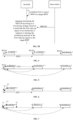
- FIG. 2 is a structural schematic diagram of a wireless communication system according to an embodiment of the disclosure.
- the wireless communication system is a communication system based on cellular mobile communication technology.
- the wireless communication system may include several terminals 110 and several base stations 120.
- the terminal 110 may be a device that provides voice and/or data connectivity to the user.
- the terminal 110 can communicate with one or more core networks via a radio access network (RAN).
- RAN radio access network
- the terminal 110 can be an IoT terminal, such as a sensor device, a mobile phone (or a cellular phone), and a computer with the IoT terminal, which may be for example, a fixed, portable, pocket-sized, handheld, built-in computer or on-board device, such as, a station (STA), a subscriber unit, a subscriber station, a mobile station, a mobile, a remote station, an access point, a remote terminal, an access terminal, a user terminal, a user agent, a user device, or a user equipment (UE).
- STA station
- UE user equipment
- the terminal 110 may also be a device with an unmanned aerial vehicle, or may also be an on-board device, for example, an electronic control unit (ECU) having a wireless communication function, or a wireless communication device externally connected to the ECU.
- the terminal 110 may also be a roadside device, such as, a street lamp, signal lamp, or other roadside device having a wireless communication function.
- the base station 120 may be a network side device in a wireless communication system.
- the wireless communication system may be the 4th generation mobile communication (4G) system, also known as the long term evolution (LTE) system.
- the wireless communication system may also be a 5G system, also known as the new radio (NR) system or 5G NR system.
- the wireless communication system may also be a next-generation system of the 5G system.
- the access network in the 5G system can be called new generation-radio access network (NG-RAN).
- NG-RAN new generation-radio access network
- the base station 120 may be an evolved base station (eNB) adopted in the 4G system.
- the base station 120 may also be a base station (gNB) adopting a centralized and distributed architecture in the 5G system.
- the base station 120 adopts the centralized and distributed architecture it generally includes a central unit (CU) and at least two distributed units (DUs).
- the CU is provided with a packet data convergence protocol (PDCP) layer, a radio link control (RLC) layer, and a protocol stack of a media access control (MAC) layer.
- the DU is provided with a protocol stack of a physical (PHY) layer, and the embodiment of the disclosure does not limit the specific implementation of the base station 120.
- PDCP packet data convergence protocol
- RLC radio link control
- MAC media access control
- PHY physical
- the wireless connection can be established between the base station 120 and the terminal 110 through a wireless air interface.
- the wireless air interface is a wireless air interface based on the 4G standard.
- the wireless air interface is a wireless air interface based on the 5G standard.
- the wireless air interface is a NR; or, the wireless air interface can also be a wireless air interface based on a standard of next generation mobile communication network technology based on the 5G standard.
- an end to end (E2E) connection may also be established among the terminals 110, for example, scenes for vehicle to vehicle (V2V) communication, vehicle to Infrastructure (V2I) communication and vehicle to pedestrian (V2P) communication in a vehicle to everything (V2X) communication.
- V2V vehicle to vehicle
- V2I vehicle to Infrastructure
- V2P vehicle to pedestrian
- V2X vehicle to everything
- the wireless communication system may further include a network management device 130.
- the network management device 130 may be a core network device in the wireless communication system.
- the network management device 130 may be a mobility management entity (MME) in an evolved packet core (EPC).
- the network management device may also be other core network devices, such as a serving gateway (SGW), a public data network gateway (PGW), and a policy and charging rules function (PCRF) unit or a home subscriber server (HSS).
- SGW serving gateway
- PGW public data network gateway
- PCRF policy and charging rules function
- HSS home subscriber server
- the embodiments provide a method for monitoring a PDCCH includes: switching from a source band width part (BWP) to a target BWP; and monitoring the PDCCH according to a monitoring strategy based on a result that a first wake-up signal is monitored, in response to missing a monitoring moment of the first wake-up signal on the target BWP.
- BWP source band width part
- the embodiments provide a method for monitoring a PDCCH includes: switching from the source BWP to the target BWP; and stopping monitoring the PDCCH according to a monitoring strategy based on a result that the first wake-up signal is not monitored, in response to missing the monitoring moment of the first wake-up signal on the target BWP.
- the terminal switches on different BWPs, and switching from the source BWP to the target BWP includes: establishing a connection between the terminal and the base station through the source BWP is changed to establishing a connection between the terminal and the base station through the target BWP; and/or interactions between the terminal and the base station through the source BWP is changed to interactions between the terminal and the base station through the target BWP, in which the content of interactions includes: data, signal and/or signaling.
- a wake up signal is set on both the source BWP and the target BWP.
- the base station sends a WUS before the on-duration of the DRX cycle, in which the WUS is used to inform the terminal whether it is necessary to maintain the awake state within one or more on-durations behind the WUS, to monitor the PDCCH within the on-durations.
- WUS is a low-power detection signal, so that the terminal can detect or monitor the WUS with very low power consumption. Based on the WUS monitoring result, it is further determined whether it is necessary to monitor the PDCCH within the corresponding on-duration. If the WUS corresponding to the on-duration is not monitored by the terminal, this on-duration can be skipped, that is, the dormant state is still maintained within the on-duration, so that the PDCCH is not monitored, which further saves the power consumption of the terminal.
- the first wake-up signal is a type of WUS.
- the first wake-up signal is: the WUS for a monitoring moment being a switching moment when the terminal switches to the target BWP.
- the first wake-up signal is: the previous WUS for the monitoring moment being located before the switching moment when the terminal switches to the target BWP.
- the terminal switches to the target BWP at the moment T0, and the moment T1 before the moment T0 is the monitoring moment of a WUS 1, and the first wake-up signal is the WUS 1 that needs to be monitored at the moment T1.
- some terminals when balancing bandwidth load, some terminals may be switched from the source BWP to the target BWP.
- the terminal switches to the target BWP, it may just miss the monitoring moment of the first wake-up signal on the target BWP. At this time, the terminal does not know how to monitor the PDCCH within the on-duration.
- the terminal in this embodiment may monitor the PDCCH according to the monitoring strategy based on a result that a first wake-up signal is monitored currently, or not monitor the PDCCH based on a result that the first wake-up signal is not monitored currently. In this way, it may reduce processing disorder phenomenon of the terminal caused by a situation where the terminal does not know how to process.
- monitoring the PDCCH includes monitoring whether there is signal transmission on the PDCCH.
- the PDCCH can be used to transmit a PDCCH signaling.
- the PDCCH corresponds to specific time-frequency resources.
- the terminal monitors the PDCCH during the on-duration, it can perform signal detection on the time-frequency resources corresponding to the PDCCH, thereby realizing the monitoring of the PDCCH.
- the result that the WUS is monitored includes but are not limited to: monitoring that a signal intensity of the WUS on the corresponding bandwidth reaches a threshold value; and if the WUS is not monitored or the intensity of the monitored WUS does not reach the threshold value, it may be determined that the WUS is not monitored.
- monitoring the PDCCH based on the result that the first wake-up signal is monitored according to the monitoring strategy includes: according to the monitoring strategy, monitoring the PDCCH within on-durations of an effective range of the first wake-up signal based on the result that the first wake-up signal is monitored.
- One WUS corresponds to a specific monitoring range of the PDCCH, and the monitoring range may be the aforementioned effective range.
- one WUS may correspond to one or more on-durations in the DRX cycle, and these on-durations are the effective range corresponding to the WUS.
- FIG. 4 is a schematic diagram of one WUS corresponding to one on-duration.
- on-duration 1, on-duration 2 and on-duration 3 correspond to their respective WUSs, i.e., WUS1, WUS2 and WUS3.
- FIG. 5 is a schematic diagram of one WUS corresponding to N on-durations. In this way, if a WUS is monitored by the terminal, it needs to monitor the PDCCH within the N on-durations corresponding to the WUS.
- one WUS corresponds to three on-durations, namely, on-duration a, on-duration a+1, and on-duration a+2.
- the effective range of the first wake-up signal missed in this embodiment may include one or more on-durations.
- the PDCCH in response to missing the wake-up signal on the target BWP, the PDCCH may be monitored within the effective range of the first wake-up signal based on the result that the first wake-up signal is monitored, according to the monitoring strategy, which reduces unnecessary power consumption of the terminal caused by monitoring outside the effective range.
- monitoring the PDCCH within the on-durations of the effective range of the first wake-up signal includes: when the first wake-up signal corresponds to one of the on-durations, and the on-duration for the first wake-up signal has started, monitoring the PDCCH within a remaining duration of the on-duration for the first wake-up signal that has started at a current moment.
- the current moment here includes: a moment when the terminal switches to the target BWP.
- one WUS corresponds to one on-duration
- the effective range is an on-duration
- the PDCCH is monitored within this on-duration.
- the terminal switches from the source BWP to the target BWP, not only has it missed the monitoring of the first wake-up signal on the target BWP, but also the on-duration corresponding to the first wake-up signal has started. Then, starting from the current moment, the PDCCH is monitored within the remaining duration of the on-duration that has started, thereby avoiding missing important content sent by the PDCCH.
- one WUS corresponds to one on-duration.
- FIG. 6 shows that there are two cases.
- the terminal switches to the target BWP.
- the terminal monitors the PDCCH from the current moment to the end moment in the on-duration 1 based on the result that the first wake-up signal is monitored according to the monitoring strategy.
- the terminal switches to the target BWP at the moment T2 which is located in the on-duration n.
- the terminal missed the monitoring moment (i.e., the moment indicated by the upward solid arrow in FIG. 6 ) of the first wake-up signal, and monitored the PDCCH in the remaining duration of the on-duration n.
- the terminal monitors the PDCCH within the entire on-duration corresponding to the current awaking moment.
- the terminal switches to the target BWP between the monitoring moment of the first wake-up signal on the target BWP and the start moment of the on-duration. At this time, the terminal monitors the PDCCH in the entire on-duration for the first wake-up signal.
- the terminal switches to the target BWP at the moment T2 which is located between the start moment of the on-duration n corresponding to the first wake-up signal and the monitoring moment of the first wake-up signal on the target BWP. In this way, the terminal monitors the PDCCH within the entire on-duration n.
- monitoring the PDCCH within the on-durations of the effective range of the first wake-up signal includes: when the first wake-up signal corresponds to N on-durations, and the N on-durations for the first wake-up signal have started, monitoring the PDCCH within a remaining duration of the currently started on-duration and within M remaining on-durations behind the currently started on-duration for the first wake-up signal, where N is a positive integer being not less than 2, and M is a positive integer being less than N.
- N 4
- M can be any integer less than 4, for example, 3, 2, or 1.
- the PDCCH is monitored within a remaining duration of the currently started on-duration and within remaining on-durations. For example, if the terminal switches to the target BWP during the first on-duration, when the first on-duration is not over, the terminal monitors the PDCCH in the remaining duration of the first on-duration and the second to fourth on-durations.
- monitoring the PDCCH within the on-durations of the effective range of the first wake-up signal includes: when the first wake-up signal corresponds to N on-durations, and the N on-durations for the first wake-up signal have started, monitoring the PDCCH within M on-durations behind the currently started on-duration for the first wake-up signal, where N is a positive integer being not less than 2, and M is a positive integer being less than N.
- the PDCCH may be monitored within only M on-durations behind the current on-duration, i.e., the PDCCH may be not monitored within the current on-duration.
- the terminal may not continue to monitor the PDCCH within the remaining duration of the first on-duration that has started but not ended, but start monitoring the PDCCH directly starting from the second on-duration, i.e., monitoring the PDCCH within the second on-duration and the third on-duration.
- monitoring the PDCCH within the on-durations of the effective range of the first wake-up signal includes: when the first wake-up signal corresponds to N on-durations, and M on-durations for the first wake-up signal have not started, monitoring the PDCCH within the M on-durations for the first wake-up signal, where M is a positive integer being less than or equal to N.
- the terminal may monitor the PDCCH within N on-durations on the target BWP.
- a first wake-up signal (indicated by an upward solid arrow in FIG. 7 ) corresponds to 3 on-durations, namely, on-duration n, on-duration n+1, and on-duration n+2.
- the terminal may miss the monitoring moment of the first wake-up signal, in which t1 is located before the start moment of the first on-duration among the three on-durations for the first wake-up signal.
- the terminal monitors the PDCCH in the on-duration n, the on-duration n+1, and the on-duration n+2 in sequence.
- the terminal may miss the monitoring moment of the first wake-up signal, in which t2 is located after the first on-duration among the three on-durations for the first wake-up signal starts. At this time, the terminal monitors the PDCCH within the remaining duration of the on-duration n, the on-duration n+1, and the on-duration n+2 in sequence.
- the terminal may miss the monitoring moment of the first wake-up signal, in which t2 is located after the first on-duration among the three on-durations for the first wake-up signal starts. At this time, the terminal monitors the PDCCH in the on-duration n+1 and the on-duration n+2 in sequence.
- the terminal may miss the monitoring moment of the first wake-up signal, in which t3 is located after the first on-duration among the three on-durations for the first wake-up signal ends and before the on-duration n+1 starts. At this time, the terminal monitors the PDCCH in the on-duration n+1 and the on-duration n+2 in sequence.
- stopping monitoring the PDCCH based on the result that the first wake-up signal is not monitored includes: stopping monitoring the PDCCH according to the monitoring strategy within on-durations of the effective range of the first wake-up signal based on the result that the first wake-up signal is not monitored.
- the monitoring result of missing the first wake-up signal at the monitoring moment is that the WUS is not monitored. If the WUS is not monitored, the terminal can continue to keep in the dormant state within the on-duration, thereby further reducing the power consumption of the terminal.
- one first wake-up signal corresponds to one on-duration, which indicates that the effective range of the first wake-up signal includes one on-duration.
- a first wake-up signal corresponds to one on-duration. Since the first wake-up signal is not monitored at the monitoring moment according to the monitoring strategy, the PDCCH is no longer monitored in the on-duration corresponding to the first wake-up signal.
- This non-monitoring of the PDCCH includes: non-monitoring of the PDCCH within the remaining duration of the current on-duration.
- stopping monitoring the PDCCH within the on-durations of the effective range of the first wake-up signal includes: when the first wake-up signal corresponds to one of the on-durations, and the on-duration for the first wake-up signal has not started, stopping monitoring the PDCCH within the on-duration for the first wake-up signal.
- the terminal If the on-duration for the first wake-up signal has not started, after the terminal switches to the target BWP, the terminal is maintained in the dormant state within the on-duration for the first wake-up signal has not started, so the PDCCH is not monitored.
- stopping monitoring the PDCCH within the on-durations of the effective range of the first wake-up signal includes: when the first wake-up signal corresponds to N on-durations, and the N on-durations for the first wake-up signal have started, stopping monitoring the PDCCH within a remaining duration of the currently started on-duration and within M remaining on-durations behind the currently started on-duration, where N is a positive integer being not less than 2, and M is a positive integer being less than N.
- the terminal switches to the target BWP within N on-durations for the first wake-up signal. At this time, the terminal stops monitoring the PDCCH directly from the remaining duration of the currently started on-duration and the M remaining on-durations.
- the currently started on-duration is an on-duration including the current moment.
- stopping monitoring the PDCCH within the on-durations of the effective range of the first wake-up signal includes: when the first wake-up signal corresponds to N on-durations, and M on-durations for the first wake-up signal have not started, stopping monitoring the PDCCH within the M on-durations for the first wake-up signal, where N is a positive integer being not less than 2, and M is a positive integer being less than or equal to N.
- One first wake-up signal corresponds to N on-durations, which means that the effective range of the first wake-up signal includes N on-durations.
- the terminal may switch to the target BWP before the first on-duration starts, and at this time, the PDCCH is not monitored within the N on-durations for the first wake-up signal.
- the terminal may switch to the target BWP at a dormant moment between two adjacent on-durations of N on-durations. At this time, the terminal does not monitor the PDCCH within the M on-durations behind the current moment.
- the method further includes: determining the result that the first wake-up signal is monitored or the result that the first wake-up signal is not monitored, in response to switching from the source BWP to the target BWP and missing the monitoring moment of the first wake-up signal on the target BWP.
- the result that the first wake-up signal is monitored or the result that the first wake-up signal is not monitored can be determined before monitoring the PDCCH.
- One way is to directly determine that the monitoring result of the first wake-up signal missed on the target BWP based on the configuration information is being monitored or not being monitored.
- the configuration of different BWP is different. According to the configuration of the current BWP, it can be directly determined whether the WUS is monitored or not at the current moment missing the monitoring moment.
- determining the result that the first wake-up signal is monitored or the result that the first wake-up signal is not monitored includes: determining the result that the first wake-up signal is monitored or the result that the first wake-up signal is not monitored based on configuration information.
- the configuration information can be one written in the protocol in advance.
- the configuration information may be one sent by the base station to the terminal, and the terminal may send the configuration information to the terminal through a PHY layer signaling or a high-layer signaling.
- the configuration information can clarify that in response to missing the first wake-up signal on the target BWP, it is determined that the result that the first wake-up signal is monitored or the result that the first wake-up signal is not monitored.
- determining the result that the first wake-up signal is monitored or the result that the first wake-up signal is not monitored includes: determining the result that the first wake-up signal is monitored or the result that the first wake-up signal is not monitored based on a monitoring result of a second wake-up signal.
- the second wake-up signal is one before the first wake-up signal.
- the monitoring result of the second wake-up signal reflects the current frequency of service dispatching by the terminal.
- the service dispatching can be divided into high-occurrence scenarios and low-occurrence scenarios according to the comparison of its current dispatching frequency with specific thresholds.
- the frequency of service dispatching in the high-occurrence scenario is higher than that of service dispatching in the low-occurrence scenario. In this way, the monitoring result of the first wake-up signal can be determined according to the monitoring result of the second wake-up signal.
- the terminal can determine that the monitoring result of the missed first wake-up signal is being monitored, so that the terminal can maintain the awake state within one or more on-durations for the first wake-up signal to monitor the PDCCH.
- various signalings transmitted on the PDCCH such as a signaling for service dispatching, is received, so that data is sent and received in time based on the signaling for service dispatching, and the data transmission delay is reduced.
- the terminal can determine that the monitoring result of the first wake-up signal is not being monitored based on the historical monitoring result of the WUS. At this time, the terminal stays dormant within one or more on-durations for the first wake-up signal in the low-occurrence scenario, so that the PDCCH is not monitored, and power consumption caused by unnecessary monitoring is reduced.
- determining the result included in the monitoring strategy that the first wake-up signal is monitored based on the monitoring result of the second wake-up signal includes: determining that the first wake-up signal is monitored when W1 second wake-up signals are continuously monitored on the source BWP before the current moment, where W1 is a positive integer.
- determining the result included in the monitoring strategy that the first wake-up signal is monitored based on the monitoring result of the second wake-up signal includes: determining the result that the first wake-up signal is monitored when W2 second wake-up signals are continuously monitored on the source BWP in a predetermined duration, where W2 is a positive integer.
- the preset time period may be any time period, and may be any time period specified in the configuration information.
- the end time of the preset time period may be the current time, or the switching time when the terminal switches to the target BWP, or any time before the switching moment.
- the terminal may determine a result that the first wake-up is monitored as a reference basis for subsequent PDCCH monitoring.
- W1 and W2 may be equal or different.
- determining a result of the first wake-up signal included in the monitoring strategy based on the monitoring result of the second wake-up signal includes: in a duration T1 before the current moment, if S second wake-up signals are monitored on the source BWP, determining that the first wake-up signal on the target BWP is monitored.
- the S second wake-up signals may be continuous wake-up signals or discontinuous signals.
- determining the result that the first wake-up signal is monitored or not monitored includes: determining the result that the first wake-up signal is monitored or not monitored based on determination information.
- the determination information includes but is not limited to: determination parameters and/or determination rules.
- the determination parameter includes at least one of: the W1 or W2, and the T and S.
- the determination rule may include: if the W1 second wake-up signals are continuously monitored on the source BWP before the current moment, determining that the first wake-up signal on the target BWP is monitored; otherwise, determining that the first wake-up signal on the target BWP is not monitored.
- the terminal may determine a result that the first wake-up signal is monitored as a reference basis for subsequent PDCCH monitoring.
- S second wake-up signals are monitored on the source BWP within the duration T1 before the current moment, it is determined that the first wake-up signal on the target BWP is monitored, otherwise, it is determined that the first wake-up signal on the target BWP is not monitored.
- the method further includes: receiving a broadcast signaling carrying the determination information; or, receiving a dedicated signaling carrying the determination information.
- the broadcast signaling is a signaling sent by a broadcasting channel, for example, a physical downlink broadcast channel.
- the dedicated information may include various high-level signalings, for example, a radio resource control (RRC) signaling unicasted to the corresponding terminal.
- RRC radio resource control
- the determination information includes but is not limited to the above determination parameters and/or determination rules.
- the determination information can be sent by the base station.
- the base station can adjust the determination information adaptively according to the current needs, so as to control the terminal to switch from the source BWP to the target BWP, and to determine whether to monitor the PDCCH in the on-duration corresponding to the first wake-up signal in response to missing the monitoring moment of the first wake-up signal. Therefore, the balance between saving the power consumption of the terminal and the timeliness of interactions between the terminal and the base station is realized.
- the method includes: configuring the monitoring strategy in which the first wake-up signal corresponds to one of the on-durations, in response to switching from the source BWP to the target BWP and missing the monitoring moment of the first wake-up signal on the target BWP; or configuring the monitoring strategy in which the first wake-up signal corresponds to the N on-durations, in response to switching from the source BWP to the target BWP and missing the monitoring moment of the first wake-up signal on the target BWP, where N is a positive integer not less than 2.
- the configuration here can be configured by the terminal itself, for example, the terminal can be configured according to a built-in protocol, or according to negotiation with the base station.
- a monitoring strategy that one wake-up signal corresponds to one on-duration is pre-stored in the terminal, and a monitoring strategy that one wake-up signal corresponds to N on-durations is also stored.
- the monitoring strategy configured in this embodiment may include: according to the configuration information of currently switching to the target BWP, activating a monitoring strategy that one wake-up signal corresponds to one on-duration, or activating a monitoring strategy that one wake-up signal corresponds to N on-durations.
- the embodiments of the disclosure provide a method for sending a signaling.
- the method includes: sending a signaling including determination information.
- the signaling includes: a broadcast signaling or a dedicated signaling.
- the determination information is used to determine a result that a first wake-up signal is monitored or not monitored based on the determination information, in response to switching from a source BWP to a target BWP and missing the first wake-up signal on the target BWP.
- the method according to the embodiment can be applied to a base station, and the base station can send the determination information through the broadcast signaling or the dedicated signaling.
- the terminal can be switched from the source BWP to the target BWP, even if the first wake-up signal on the target BWP is missed, the terminal can still be instructed to monitor or not monitor the PDCCH based on the result that the first wake-up signal is monitored or not monitored.
- the method further includes: sending various signalings, such as a service dispatching signaling, through the PDCCH.
- the result that the first wake-up signal is monitored or not monitored is used by the terminal to determine whether to monitor the PDCCH.
- the embodiments of the disclosure further provide an apparatus for monitoring a PDCCH.
- the apparatus includes: a monitoring module, configured to switch from a source band width part (BWP) to a target BWP, and monitor the PDCCH according to a monitoring strategy based on a result that a first wake-up signal is monitored, in response to missing a monitoring moment of the first wake-up signal on the target BWP.
- BWP source band width part
- the monitoring module is configured to switch from the source BWP to the target BWP, and stop monitoring the PDCCH according to a monitoring strategy based on a result that the first wake-up signal is not monitored, in response to missing the monitoring moment of the first wake-up signal on the target BWP.
- the monitoring module may be a program module. After the program module is executed by the processor, whether the PDCCH is monitored or not-monitored can be realized.
- the monitoring module may be a combination of software and hardware module, which includes but is not limited to a complex programmable array or a field programmable array.
- the monitoring module may be a pure hardware module, which may include, but is not limited to, an application specific integrated circuit.
- the monitoring apparatus further includes a storage module.
- the storage module may store a monitoring strategy.
- the monitoring module is configured to monitor the PDCCH according to the monitoring strategy within on-durations of an effective range of the first wake-up signal based on the result that the first wake-up signal is monitored.
- the monitoring module is configured to when the first wake-up signal corresponds to one of the on-durations, and the on-duration for the first wake-up signal has started, monitor the PDCCH within a remaining duration of the on-duration for the first wake-up signal that has started at a current moment.
- the monitoring module is configured to when the first wake-up signal corresponds to one of the on-durations, and the on-duration for the first wake-up signal has not started, monitor the PDCCH within the on-duration for the first wake-up signal.
- the monitoring module is configured to when the first wake-up signal corresponds to N on-durations, and the N on-durations for the first wake-up signal have started, monitor the PDCCH within a remaining duration of the currently started on-duration and within M remaining on-durations behind the currently started on-duration for the first wake-up signal.
- N is a positive integer not less than 2
- M is a positive integer less than N.
- the monitoring module is configured to when the first wake-up signal corresponds to N on-durations, and the N on-durations for the first wake-up signal have started, monitor the PDCCH within M on-durations behind the currently started on-duration for the first wake-up signal.
- N is a positive integer not less than 2
- M is a positive integer less than N.
- the monitoring module is configured to when the first wake-up signal corresponds to N on-durations, and M on-durations for the first wake-up signal have not started, monitor the PDCCH within the M on-durations for the first wake-up signal.
- M is a positive integer less than or equal to N.
- the monitoring module is configured to stop monitoring the PDCCH according to the monitoring strategy within on-durations of the effective range of the first wake-up signal based on the result that the first wake-up signal is not monitored.
- the monitoring module is configured to when the first wake-up signal corresponds to one of the on-durations, and the on-duration for the first wake-up signal has started, stop monitoring the PDCCH within a remaining duration of the on-duration for the first wake-up signal that has started at a current moment.
- the monitoring module is configured to when the first wake-up signal corresponds to one of the on-durations, and the on-duration for the first wake-up signal has not started, stop monitoring the PDCCH within the on-duration for the first wake-up signal.
- the monitoring module is configured to when the first wake-up signal corresponds to N on-durations, and the N on-durations for the first wake-up signal have started, stop monitoring the PDCCH within a remaining duration of the currently started on-duration and within M remaining on-durations behind the currently started on-duration, N is a positive integer being not less than 2, and M is a positive integer being less than N.
- the monitoring module is configured to when the first wake-up signal corresponds to N on-durations, and M on-durations for the first wake-up signal have not started, stop monitoring the PDCCH within the M on-durations for the first wake-up signal, N is a positive integer being not less than 2, and M is a positive integer being less than or equal to N.
- the apparatus further includes: a determining module, configured to switch from a source band width part (BWP) to a target BWP, and determine the result that the first wake-up signal is monitored or the result that the first wake-up signal is not monitored, in response to missing a monitoring moment of the first wake-up signal on the target BWP.
- a determining module configured to switch from a source band width part (BWP) to a target BWP, and determine the result that the first wake-up signal is monitored or the result that the first wake-up signal is not monitored, in response to missing a monitoring moment of the first wake-up signal on the target BWP.
- BWP source band width part
- the determining module is configured to determine the result that the first wake-up signal is monitored or the result that the first wake-up signal is not monitored based on configuration information.
- the determining module is configured to determine the result that the first wake-up signal is monitored or the result that the first wake-up signal is not monitored based on a monitoring result of a second wake-up signal, in which the second wake-up signal is a wake-up signal whose monitoring moment is before the monitoring moment of the first wake-up signal.
- the determining module is configured to perform at least one of: determining the result that the first wake-up signal is monitored when W1 second wake-up signals are continuously monitored on the source BWP before the current moment, where W1 is a positive integer; and determining the result that the first wake-up signal is monitored when W2 second wake-up signals are continuously monitored on the source BWP in a predetermined duration, where W2 is a positive integer.
- the determining module is configured to determine the result that the first wake-up signal is monitored or the result that the first wake-up signal is not monitored based on determination information.
- the apparatus further includes: a receiving module, configured to receive a broadcast signaling that carries the determination information; or, receive a dedicated signaling that carries the determination information.
- the apparatus further includes: a configuring module, configured to set a monitoring strategy that the first wake-up signal corresponds to one of the on-durations in response to switching from the source BWP to the target BWP and missing the monitoring moment of the first wake-up signal on the target BWP.
- a configuring module configured to set a monitoring strategy that the first wake-up signal corresponds to one of the on-durations in response to switching from the source BWP to the target BWP and missing the monitoring moment of the first wake-up signal on the target BWP.
- the configuring module is configured to set a monitoring strategy that the first wake-up signal corresponds to N on-durations in response to switching from the source BWP to the target BWP and missing the monitoring moment of the first wake-up signal on the target BWP, N is a positive integer being not less than 2.
- the embodiments further provide an apparatus for sending a signaling.
- the apparatus includes: a sending module, configured to send a signaling including determination information, the signaling includes: a broadcast signaling or a dedicated signaling.
- the determination information is used to determine a result that a first wake-up signal is monitored or a result that a first wake-up signal is not monitored, in response to switching from a source BWP to a target BWP and missing the first wake-up signal on the target BWP.
- the embodiments of the disclosure provide an apparatus for sending a signaling.
- the apparatus includes: a sending module, configured to send a signaling including determination information, the signaling includes: a broadcast signaling or a dedicated signaling.
- the determination information is used to determine a result that a first wake-up signal is monitored or a result that a first wake-up signal is not monitored, in response to switching from a source BWP to a target BWP and missing the first wake-up signal on the target BWP.
- the apparatus for sending a signaling can be a device applied to a network element of an access network such as a base station, and can send a signaling carrying the determination information through the sending module, so that the terminal can receive the determination information.
- the apparatus for sending a signaling further includes: a storage module.
- the storage module is connected to the sending module and can be used to store the determination information.
- the UE switches to the target BWP. If the monitoring moment of the WUS on the BWP is missed, the adopted monitoring strategy is to perform processing in response to the currently missed WUS monitoring moment based on the determination result that the WUS is monitored or the determination result that the WUS is not monitored.
- the terminal monitors the PDCCH based on the determination result that the WUS is monitored.
- the terminal stops monitoring the PDCCH based on the determination result that the WUS is not monitored.
- the missed WUS here is the aforementioned first wake-up signal.
- the adopted monitoring strategy is: processing in response to the currently missed monitoring moment of the WUS based on the determination result that the WUS is monitored, that is, monitoring within an effective range of subsequent on-durations of the WUS.
- the effective range of the WUS includes: the WUS corresponding to one of the on-durations, that is, a 1:1 mapping scenario of the WUS and one on-duration; and the WUS corresponding to a plurality of the on-durations, that is, a 1: N mapping scenario of the WUS and N on-durations.
- Example 1 Based on Example 1, this example is aimed at the 1:1 mapping scenario.
- the terminal misses the WUS on the target BWP there are several possible cases in which the PDCCH is monitored or not monitored according to the monitoring strategy.
- this example is aimed at the 1: N mapping scenario.
- the terminal misses the WUS on the target BWP there are several possible cases in which the PDCCH is monitored or not monitored according to the monitoring strategy.
- the terminal switches to the target BWP at the starting moment of the second on-duration, the terminal starts monitoring from the remaining duration of the second on-duration, which includes a part of the 2 nd on-duration and the remaining 2 on-durations.
- the terminal switches to the target BWP during the second on-duration, the terminal starts monitoring from the third on-duration, that is, continues to monitor within the remaining 2 on-durations.
- this example provides a method for determining whether the WUS missed on the BWP is monitored.
- the method includes: when the terminal switches to the target BWP and misses the monitoring moment of the WUS, in the adopted monitoring strategy that in response to the current monitoring moment of the missed WUS, processing is performed based on the result that the WUS is monitored or not monitored, whether WUS is monitored can be determined based on the specified protocol or by the terminal.
- the protocol specifies that when the terminal switches to the target BWP and misses the monitoring moment of the WUS, the adopted monitoring strategy is that processing is performed in response to the current monitoring moment of the WUS based on the result that the WUS is monitored.
- the adopted monitoring strategy is deciding in advance whether the WUS is monitored.
- the deciding process can be based on the historical WUS monitoring situations.
- the determination parameters and determination rules can be notified to the terminal in a broadcasting mode or a dedicated signaling mode.
- the adopted monitoring strategy can be configured based on 1:1 or 1: N respectively.
- the embodiment of the disclosure also provides a communication device, which may be a terminal, and can implement the method for monitoring the PDCCH according to any of the foregoing technical solutions.
- the communication device can also be a network element of an access network such as a base station, and can implement the method for sending a signaling according to any of the foregoing technical solutions.
- the communication device includes: a transceiver, a memory and a processor.
- the transceiver is configured to interact with other devices.
- the transceiver includes but is not limited to a transceiver antenna.
- the memory may store computer-executable instructions.
- the processor is connected to the transceiver and the memory respectively, and can implement the method for monitoring the PDCCH or the method for sending a signaling according to any of the foregoing technical solutions.
- FIG. 11 shows a terminal according to an exemplary embodiment.
- the terminal may be a mobile phone, a computer, a digital broadcasting terminal, a message transceiver device, a game console, a tablet device, a medical device, a fitness device and a personal digital assistant.
- the terminal 800 may include one or more of the following components: a processing component 802, a memory 804, a power component 806, a multimedia component 808, an audio component 810, an input/output (I/O) interface 812, a sensor component 814, and a communication component 816.
- the processing component 802 generally controls overall operations of the terminal 800, such as the operations associated with display, telephone calls, data communications, camera operations, and recording operations.
- the processing component 802 may include one or more processors 820 to execute instructions to perform all or part of the steps in the above described method.
- the processing component 802 may include one or more modules which facilitate the interaction between the processing component 802 and other components.
- the processing component 802 may include a multimedia module to facilitate the interaction between the multimedia component 808 and the processing component 802.
- the memory 804 is configured to store various types of data to support the operation of the terminal 800. Examples of such data include instructions for any applications or methods operated on the terminal 800, contact data, phonebook data, messages, pictures, video, etc.
- the memory 804 may be implemented using any type of volatile or non-volatile memory devices, or a combination thereof, such as a static random access memory (SRAM), an electrically erasable programmable read-only memory (EEPROM), an erasable programmable read-only memory (EPROM), a programmable read-only memory (PROM), a read-only memory (ROM), a magnetic memory, a flash memory, a magnetic or optical disk.
- SRAM static random access memory
- EEPROM electrically erasable programmable read-only memory
- EPROM erasable programmable read-only memory
- PROM programmable read-only memory
- ROM read-only memory
- magnetic memory a magnetic memory
- flash memory a flash memory
- magnetic or optical disk a magnetic or optical
- the power component 806 provides power to various components of the terminal 800.
- the power component 806 may include a power management system, one or more power sources, and any other components associated with the generation, management, and distribution of power in the terminal 800.
- the multimedia component 808 includes a screen providing an output interface between the terminal 800 and the user.
- the screen may include a liquid crystal display (LCD) and a touch panel (TP). If the screen includes the touch panel, the screen may be implemented as a touch screen to receive input signals from the user.
- the touch panel includes one or more touch sensors to sense touches, swipes, and gestures on the touch panel. The touch sensors may not only sense a boundary of a touch or swipe action, but also sense a period of time and a pressure associated with the touch or swipe action.
- the multimedia component 808 includes a front-facing camera and/or a rear-facing camera.
- the front-facing camera and/or the rear-facing camera can receive external multimedia data.
- Each front-facing camera and rear-facing camera may be a fixed optical lens system or has focal length and optical zoom capability.
- the audio component 810 is configured to output and/or input audio signals.
- the audio component 810 includes a microphone (MIC) configured to receive an external audio signal when the terminal 800 is in an operation mode, such as a call mode, a recording mode, and a voice recognition mode.
- the received audio signal may be further stored in the memory 804 or transmitted via the communication component 816.
- the audio component 810 further includes a speaker for outputting audio signals.
- the I/O interface 812 provides an interface between the processing component 802 and peripheral interface modules, such as a keyboard, a click wheel, buttons, and the like.
- the buttons may include, but are not limited to, a home button, a volume button, a starting button, and a locking button.
- the sensor component 814 includes one or more sensors to provide status assessments of various aspects of the terminal 800. For instance, the sensor component 814 may detect an open/closed status of the terminal 800, relative positioning of components, e.g., the display and the keypad, of the terminal 800, a change in position of the terminal 800 or a component of the terminal 800, a presence or absence of user contact with the terminal 800, an orientation or an acceleration/deceleration of the terminal 800, and a change in temperature of the terminal 800.
- the sensor component 814 may include a proximity sensor configured to detect the presence of nearby objects without any physical contact.
- the sensor component 814 may also include a light sensor, such as a CMOS or CCD image sensor, for use in imaging applications.
- the sensor component 814 may also include an accelerometer sensor, a gyroscope sensor, a magnetic sensor, a pressure sensor, or a temperature sensor.
- the communication component 816 is configured to facilitate communication, wired or wirelessly, between the terminal 800 and other devices.
- the terminal 800 can access a wireless network based on a communication standard, such as WiFi, 2G, or 3G, or a combination thereof.
- the communication component 816 receives a broadcast signal or broadcast associated information from an external broadcast management system via a broadcast channel.
- the communication component 816 further includes a near field communication (NFC) module to facilitate short-range communications.
- the NFC module may be implemented based on a radio frequency identity (RFID) technology, an infrared data association (IrDA) technology, an ultra-wideband (UWB) technology, a Bluetooth (BT) technology, and other technologies.
- RFID radio frequency identity
- IrDA infrared data association
- UWB ultra-wideband
- BT Bluetooth
- the terminal 800 may be implemented with one or more application specific integrated circuits (ASICs), digital signal processors (DSPs), digital signal processing devices (DSPDs), programmable logic devices (PLDs), field programmable gate arrays (FPGAs), controllers, micro-controllers, microprocessors, or other electronic components, for performing the above described method.
- ASICs application specific integrated circuits
- DSPs digital signal processors
- DSPDs digital signal processing devices
- PLDs programmable logic devices
- FPGAs field programmable gate arrays
- controllers micro-controllers, microprocessors, or other electronic components, for performing the above described method.
- non-transitory computer readable storage medium including instructions, such as included in the memory 804, executable by the processor 820 in the terminal 800, for performing the above method.
- the non-transitory computer-readable storage medium may be a ROM, a RAM, a CD-ROM, a magnetic tape, a floppy disc, an optical data storage device, and the like.
- FIG. 12 is a schematic diagram of a base station.
- the base station 900 includes a processing component 922.
- the processing component 922 further includes one or more processors, and a memory resource represented by a memory 932, for storing instructions that can be executed by the processing component 922, such as application programs.
- the application programs stored in the memory 932 may include one or more modules each corresponding to a set of instructions.
- the processing component 922 is configured to execute instructions to execute the method for monitoring a PDCCH shown in FIG. 4 and/or FIG. 5 .
- the base station may also include a power component 926 configured to perform power management of the base station 900, a wired or wireless network interface 950 configured to connect the base station 900 to a network, and an input /output (I/O) interface 958.
- the base station 900 can operate based on an operating system stored in the memory 932, such as Windows ServerTM, Mac OS XTM, UnixTM, LinuxTM, FreeBSDTM or the like.
Landscapes
- Engineering & Computer Science (AREA)
- Computer Networks & Wireless Communication (AREA)
- Signal Processing (AREA)
- Mobile Radio Communication Systems (AREA)
Claims (7)
- Verfahren zur Überwachung eines Physical Downlink Control Channels, PDCCH, mit dem Schritt:Wechseln von einem Quellenbandbreitenteil, BWP, zu einem Ziel-BWP; undgekennzeichnet durchdas Überwachen des PDCCH, innerhalb von einem Wake-up-Signal (WUS1, WUS2, WUS3) zugeordneten Einschaltzeiträumen, gemäß einer Überwachungsstrategie des Bestimmens, dass das Wake-up-Signal überwacht wird, in Reaktion auf das Fehlen eines Überwachungsmoments des Wake-up-Signals auf dem Ziel-BWP während des BWP-Wechsels, wobei die Überwachungsstrategie durch ein Protokoll vordefiniert ist, um anzugeben, dass das Wake-up-Signal in Reaktion auf das Fehlen eines Überwachungsmoments des Wake-up-Signals auf dem Ziel-BWP während des BWP-Wechsels überwacht wird.
- Verfahren nach Anspruch 1, bei welchem das Überwachen des PDCCH innerhalb der dem Wake-up-Signal zugeordneten Einschaltzeiträume einen der folgenden Schritte aufweist:wenn das Wake-up-Signal einem Einschaltzeitraum zugeordnet ist, und der dem Wake-up-Signal zugeordnete Einschaltzeitraum begonnen hat, Überwachen des PDCCH während der verbleibenden Dauer des aktuell begonnenen, dem Wake-up-Signal zugeordneten Einschaltzeitraums;wenn das Wake-up-Signal einem Einschaltzeitraum zugeordnet ist, und der dem Wake-up-Signal zugeordnete Einschaltzeitraum nicht begonnen hat, Überwachen des PDCCH während des nächsten, dem Wake-up-Signal zugeordneten Einschaltzeitraums.
- Verfahren nach Anspruch 1, bei welchem das Überwachen des PDCCH innerhalb der dem Wake-up-Signal zugeordneten Einschaltzeiträume einen der folgenden Schritte aufweist:wenn das Wake-up-Signal N Einschaltzeiträumen zugeordnet ist, und die dem Wake-up-Signal zugeordneten N Einschaltzeiträume begonnen haben, Überwachen des PDCCH während einer verbleibenden Dauer des aktuell begonnenen Einschaltzeitraums und innerhalb von M verbleibenden Einschaltzeiträumen nach dem aktuell begonnenen Einschaltzeitraum, wobei N eine positive ganze Zahl nicht kleiner als 2 ist, und M eine positive ganze Zahl kleiner als N ist;wenn das Wake-up-Signal N Einschaltzeiträumen zugeordnet ist, und die dem Wake-up-Signal zugeordneten N Einschaltzeiträume begonnen haben, Überwachen des PDCCH innerhalb von M Einschaltzeiträumen nach dem aktuell begonnenen Einschaltzeitraum, wobei N eine positive ganze Zahl nicht kleiner als 2 ist, und M eine positive ganze Zahl kleiner als N ist;wenn das Wake-up-Signal N Einschaltzeiträumen zugeordnet ist, und M dem Wake-up-Signal zugeordnete Einschaltzeiträume nicht begonnen haben, Überwachen des PDCCH innerhalb der M dem Wake-up-Signal zugeordneten Einschaltzeiträume, wobei N eine positive ganze Zahl nicht kleiner als 2 ist, und M eine positive ganze Zahl kleiner als oder gleich N ist.
- Verfahren nach einem der Ansprüche 1 bis 3, ferner mit den Schritten:Konfigurieren der Überwachungsstrategie, bei welcher das Wake-up-Signal einem Einschaltzeitraum zugeordnet ist, in Reaktion auf den Wechsel von dem Quellen-BWP zum Ziel-BWP und dem Fehlen des Überwachungsmoments des Wake-up-Signals auf dem Ziel-BWP; oderKonfigurieren der Überwachungsstrategie, bei welcher das Wake-up-Signal den N Einschaltzeiträumen zugeordnet ist, in Reaktion auf den Wechsel von dem Quellen-BWP zum Ziel-BWP und dem Fehlen des Überwachungsmoments des Wake-up-Signals auf dem Ziel-BWP, wobei N eine positive ganze Zahl nicht kleiner als 2 ist.
- Vorrichtung zum Überwachen eines Physical Downlink Control Channels, PDCCH, mit:einem Überwachungsmodul, das dazu ausgebildet ist, von einem Quellenbandbreitenteil, BWP, zu einem Ziel-BWP zu wechseln; unddadurch gekennzeichnet, dass das Überwachungsmodul ferner dazu ausgebildet ist,innerhalb von einem Wake-up-Signal (WUS1, WUS2, WUS3) zugeordneten Einschaltzeiträumen, den PDCCH gemäß einer Überwachungsstrategie des Bestimmens, dass das Wake-up-Signal überwacht wird, in Reaktion auf das Fehlen eines Überwachungsmoments des Wake-up-Signals auf dem Ziel-BWP während des BWP-Wechsels, zu überwachen, wobei die Überwachungsstrategie durch ein Protokoll vordefiniert ist, um anzugeben, dass das Wake-up-Signal in Reaktion auf das Fehlen eines Überwachungsmoments des Wake-up-Signals auf dem Ziel-BWP während des BWP-Wechsels überwacht wird.
- Vorrichtung nach Anspruch 5, bei welcher das Überwachungsmodul dazu ausgebildet ist, einen der folgenden Schritte durchzuführen:wenn das Wake-up-Signal einem Einschaltzeitraum zugeordnet ist, und der dem Wake-up-Signal zugeordnete Einschaltzeitraum begonnen hat, Überwachen des PDCCH während der verbleibenden Dauer des aktuell begonnenen, dem Wake-up-Signal zugeordneten Einschaltzeitraums;wenn das Wake-up-Signal einem Einschaltzeitraum zugeordnet ist, und der dem Wake-up-Signal zugeordnete Einschaltzeitraum nicht begonnen hat, Überwachen des PDCCH während des nächsten, dem Wake-up-Signal zugeordneten Einschaltzeitraums.
- Vorrichtung nach Anspruch 5, bei welcher das Überwachungsmodul dazu ausgebildet ist, einen der folgenden Schritte durchzuführen:wenn das Wake-up-Signal N Einschaltzeiträumen zugeordnet ist, und die dem Wake-up-Signal zugeordneten N Einschaltzeiträume begonnen haben, Überwachen des PDCCH während einer verbleibenden Dauer des aktuell begonnenen Einschaltzeitraums und innerhalb von M verbleibenden Einschaltzeiträumen nach dem aktuell begonnenen Einschaltzeitraum, wobei N eine positive ganze Zahl nicht kleiner als 2 ist, und M eine positive ganze Zahl kleiner als N ist;wenn das Wake-up-Signal N Einschaltzeiträumen zugeordnet ist, und die dem Wake-up-Signal zugeordneten N Einschaltzeiträume begonnen haben, Überwachen des PDCCH innerhalb von M Einschaltzeiträumen nach dem aktuell begonnenen Einschaltzeitraum, wobei N eine positive ganze Zahl nicht kleiner als 2 ist, und M eine positive ganze Zahl kleiner als N ist;wenn das Wake-up-Signal N Einschaltzeiträumen zugeordnet ist, und M dem Wake-up-Signal zugeordnete Einschaltzeiträume nicht begonnen haben, Überwachen des PDCCH innerhalb der M dem Wake-up-Signal zugeordneten Einschaltzeiträume, wobei N eine positive ganze Zahl nicht kleiner als 2 ist, und M eine positive ganze Zahl kleiner als oder gleich N ist.
Applications Claiming Priority (1)
| Application Number | Priority Date | Filing Date | Title |
|---|---|---|---|
| PCT/CN2019/088433 WO2020237446A1 (zh) | 2019-05-24 | 2019-05-24 | 监听方法、信令下发方法及装置、通信设备及存储 |
Publications (3)
| Publication Number | Publication Date |
|---|---|
| EP3979718A1 EP3979718A1 (de) | 2022-04-06 |
| EP3979718A4 EP3979718A4 (de) | 2022-06-01 |
| EP3979718B1 true EP3979718B1 (de) | 2024-11-20 |
Family
ID=68150190
Family Applications (1)
| Application Number | Title | Priority Date | Filing Date |
|---|---|---|---|
| EP19930367.8A Active EP3979718B1 (de) | 2019-05-24 | 2019-05-24 | Pdcch überwachungsverfahren und -einrichtung |
Country Status (10)
| Country | Link |
|---|---|
| US (1) | US11991631B2 (de) |
| EP (1) | EP3979718B1 (de) |
| JP (1) | JP7247374B2 (de) |
| KR (1) | KR102813648B1 (de) |
| CN (1) | CN110337830B (de) |
| BR (1) | BR112021023337A2 (de) |
| ES (1) | ES3000013T3 (de) |
| FI (1) | FI3979718T3 (de) |
| SG (1) | SG11202112995RA (de) |
| WO (1) | WO2020237446A1 (de) |
Families Citing this family (12)
| Publication number | Priority date | Publication date | Assignee | Title |
|---|---|---|---|---|
| CN111800801B (zh) * | 2019-08-16 | 2022-05-27 | 维沃移动通信有限公司 | Pdcch的监听方法和设备 |
| CN112543079B (zh) * | 2019-09-23 | 2021-09-24 | 维沃移动通信有限公司 | 一种pdcch监听控制方法及相关设备 |
| CN114616874B (zh) * | 2019-11-07 | 2024-05-17 | 高通股份有限公司 | 用于免许可频谱的cdrx唤醒信号 |
| CN115002853B (zh) * | 2019-11-12 | 2023-10-10 | Oppo广东移动通信有限公司 | 一种非连续接收处理方法、终端设备 |
| WO2021104615A1 (en) * | 2019-11-27 | 2021-06-03 | Telefonaktiebolaget Lm Ericsson (Publ) | Selective wake-up signal monitoring |
| WO2021104616A1 (en) | 2019-11-27 | 2021-06-03 | Telefonaktiebolaget Lm Ericsson (Publ) | Wake-up signal monitoring optimization |
| WO2021114047A1 (zh) * | 2019-12-09 | 2021-06-17 | Oppo广东移动通信有限公司 | 一种非连续接收持续定时器控制方法、电子设备及存储介质 |
| JP7622075B2 (ja) * | 2020-01-31 | 2025-01-27 | クアルコム,インコーポレイテッド | ワイヤレスネットワークにおけるウェイクアップ信号(wus)とダウンリンク測位基準信号(prs)受信との対話 |
| US20230047726A1 (en) * | 2020-03-20 | 2023-02-16 | Qualcomm Incorporated | Low complexity physical downlink control channel |
| JP7701012B2 (ja) * | 2021-03-26 | 2025-07-01 | 株式会社Nttドコモ | 端末、及び無線通信システム |
| CN115190500B (zh) * | 2021-04-01 | 2025-10-28 | 维沃移动通信有限公司 | 传输处理方法、终端及网络侧设备 |
| WO2025112054A1 (zh) * | 2023-12-01 | 2025-06-05 | Oppo广东移动通信有限公司 | 一种无线通信方法及设备、存储介质 |
Family Cites Families (14)
| Publication number | Priority date | Publication date | Assignee | Title |
|---|---|---|---|---|
| MX2019001434A (es) | 2016-08-10 | 2019-09-06 | Idac Holdings Inc | Metodos y aparato para ahorrar energía de manera eficiente en redes inalámbricas. |
| CN108270536B (zh) * | 2017-01-03 | 2020-10-20 | 电信科学技术研究院 | 一种监听指示及监听方法、装置 |
| KR102479286B1 (ko) * | 2017-05-04 | 2022-12-20 | 아이피엘에이 홀딩스 인크. | 웨이크 업 신호들 동작 |
| CN109429258B (zh) * | 2017-07-17 | 2021-10-29 | 中国移动通信有限公司研究院 | 一种信道监听的指示方法、监听方法、终端及网络侧设备 |
| CN109327889B (zh) * | 2017-07-31 | 2024-05-31 | 北京三星通信技术研究有限公司 | 一种指示信息的检测方法和设备 |
| EP3689043B1 (de) * | 2017-09-28 | 2023-05-03 | Telefonaktiebolaget LM Ericsson (publ) | Mobilitätsrobustheit für wecksignale mit diskontinuierlichem empfang |
| CN109769309B (zh) * | 2017-11-09 | 2021-06-22 | 中国移动通信有限公司研究院 | 一种非连续监听的方法、设备及计算机可读存储介质 |
| KR102352684B1 (ko) * | 2017-11-16 | 2022-01-18 | 삼성전자주식회사 | 무선통신 시스템에서 통신 방법 및 장치 |
| CN109219116B (zh) * | 2018-08-09 | 2022-05-31 | 华为技术有限公司 | 一种终端设备的休眠方法及装置 |
| CN109314869B (zh) * | 2018-08-24 | 2022-04-15 | 北京小米移动软件有限公司 | 非连续接收drx参数的配置方法及装置 |
| US11877242B2 (en) * | 2018-10-17 | 2024-01-16 | Beijing Xiaomi Mobile Software Co., Ltd. | Bandwidth part switching method and apparatus |
| CN109496446A (zh) * | 2018-10-19 | 2019-03-19 | 北京小米移动软件有限公司 | 信道监听方法及装置 |
| US11937183B2 (en) * | 2018-10-19 | 2024-03-19 | Beijing Xiaomi Mobile Software Co., Ltd. | Method and device for monitoring power-saving signal |
| US12267777B2 (en) * | 2018-11-27 | 2025-04-01 | Beijing Xiaomi Mobile Software Co., Ltd. | Terminal wake-up control method, device and storage medium |
-
2019
- 2019-05-24 CN CN201980000944.XA patent/CN110337830B/zh active Active
- 2019-05-24 WO PCT/CN2019/088433 patent/WO2020237446A1/zh not_active Ceased
- 2019-05-24 ES ES19930367T patent/ES3000013T3/es active Active
- 2019-05-24 EP EP19930367.8A patent/EP3979718B1/de active Active
- 2019-05-24 FI FIEP19930367.8T patent/FI3979718T3/fi active
- 2019-05-24 BR BR112021023337A patent/BR112021023337A2/pt unknown
- 2019-05-24 JP JP2021567072A patent/JP7247374B2/ja active Active
- 2019-05-24 SG SG11202112995RA patent/SG11202112995RA/en unknown
- 2019-05-24 KR KR1020217041468A patent/KR102813648B1/ko active Active
- 2019-05-24 US US17/613,148 patent/US11991631B2/en active Active
Also Published As
| Publication number | Publication date |
|---|---|
| BR112021023337A2 (pt) | 2022-01-04 |
| JP7247374B2 (ja) | 2023-03-28 |
| US20220322232A1 (en) | 2022-10-06 |
| ES3000013T3 (en) | 2025-02-27 |
| JP2022533071A (ja) | 2022-07-21 |
| KR20220009452A (ko) | 2022-01-24 |
| CN110337830B (zh) | 2021-06-18 |
| SG11202112995RA (en) | 2021-12-30 |
| KR102813648B1 (ko) | 2025-05-30 |
| FI3979718T3 (fi) | 2024-12-20 |
| EP3979718A4 (de) | 2022-06-01 |
| WO2020237446A1 (zh) | 2020-12-03 |
| US11991631B2 (en) | 2024-05-21 |
| EP3979718A1 (de) | 2022-04-06 |
| CN110337830A (zh) | 2019-10-15 |
Similar Documents
| Publication | Publication Date | Title |
|---|---|---|
| EP3979718B1 (de) | Pdcch überwachungsverfahren und -einrichtung | |
| EP4106416B1 (de) | Kommunikationsverarbeitungsverfahren und -vorrichtung | |
| CN111406378B (zh) | 通信方法、装置及计算机存储介质 | |
| CN110771222B (zh) | 寻呼配置方法、装置、通信设备及存储介质 | |
| US12225465B2 (en) | Monitoring method, instruction sending method and device, and communication apparatus | |
| CN112020882B (zh) | 省电信号处理方法及装置、通信设备及存储介质 | |
| CN111543118B (zh) | Rrc状态改变的方法、装置、通信设备及存储介质 | |
| US12501366B2 (en) | State control method and communication device | |
| US12432658B2 (en) | Information processing method and apparatus based on DCP in DRX short cycle mode, and communication device and storage medium | |
| CN110521275A (zh) | 监听处理、策略下发方法及装置、通信设备及存储 | |
| US20240088966A1 (en) | Information processing method and apparatus, communication device, and storage medium | |
| US12477619B2 (en) | Short cycle configuration method and apparatus, communication device, and storage medium | |
| CN111201814B (zh) | 非连续接收的处理方法及装置 | |
| US20250024350A1 (en) | Information transmission method and apparatus, communication device, and storage medium | |
| EP4447495A1 (de) | Informationsverarbeitungsverfahren und -vorrichtung, kommunikationsvorrichtung und speichermedium | |
| EP4290950A1 (de) | Verfahren und vorrichtung zur bestimmung einer benutzerfunkrufgruppe sowie benutzervorrichtung und speichermedium | |
| WO2022205046A1 (zh) | 信息传输方法、装置、通信设备和存储介质 | |
| WO2022178728A1 (zh) | Drx周期的处理方法、装置、通信设备及存储介质 | |
| RU2783839C1 (ru) | Способ контроля и устройство связи | |
| US20250203526A1 (en) | Information processing method and apparatus, and communication device and storage medium | |
| US20240098768A1 (en) | Information transmission methods, and communication devices |
Legal Events
| Date | Code | Title | Description |
|---|---|---|---|
| STAA | Information on the status of an ep patent application or granted ep patent |
Free format text: STATUS: THE INTERNATIONAL PUBLICATION HAS BEEN MADE |
|
| PUAI | Public reference made under article 153(3) epc to a published international application that has entered the european phase |
Free format text: ORIGINAL CODE: 0009012 |
|
| STAA | Information on the status of an ep patent application or granted ep patent |
Free format text: STATUS: REQUEST FOR EXAMINATION WAS MADE |
|
| 17P | Request for examination filed |
Effective date: 20211221 |
|
| AK | Designated contracting states |
Kind code of ref document: A1 Designated state(s): AL AT BE BG CH CY CZ DE DK EE ES FI FR GB GR HR HU IE IS IT LI LT LU LV MC MK MT NL NO PL PT RO RS SE SI SK SM TR |
|
| A4 | Supplementary search report drawn up and despatched |
Effective date: 20220502 |
|
| RIC1 | Information provided on ipc code assigned before grant |
Ipc: H04W 72/04 20090101ALN20220425BHEP Ipc: H04W 76/28 20180101ALI20220425BHEP Ipc: H04W 52/02 20090101AFI20220425BHEP |
|
| DAV | Request for validation of the european patent (deleted) | ||
| DAX | Request for extension of the european patent (deleted) | ||
| STAA | Information on the status of an ep patent application or granted ep patent |
Free format text: STATUS: EXAMINATION IS IN PROGRESS |
|
| 17Q | First examination report despatched |
Effective date: 20230113 |
|
| GRAP | Despatch of communication of intention to grant a patent |
Free format text: ORIGINAL CODE: EPIDOSNIGR1 |
|
| STAA | Information on the status of an ep patent application or granted ep patent |
Free format text: STATUS: GRANT OF PATENT IS INTENDED |
|
| RIC1 | Information provided on ipc code assigned before grant |
Ipc: H04W 72/0453 20230101ALN20240619BHEP Ipc: H04W 76/28 20180101ALI20240619BHEP Ipc: H04W 52/02 20090101AFI20240619BHEP |
|
| INTG | Intention to grant announced |
Effective date: 20240705 |
|
| RIC1 | Information provided on ipc code assigned before grant |
Ipc: H04W 72/0453 20230101ALN20240625BHEP Ipc: H04W 76/28 20180101ALI20240625BHEP Ipc: H04W 52/02 20090101AFI20240625BHEP |
|
| P01 | Opt-out of the competence of the unified patent court (upc) registered |
Free format text: CASE NUMBER: APP_45942/2024 Effective date: 20240808 |
|
| GRAS | Grant fee paid |
Free format text: ORIGINAL CODE: EPIDOSNIGR3 |
|
| GRAA | (expected) grant |
Free format text: ORIGINAL CODE: 0009210 |
|
| STAA | Information on the status of an ep patent application or granted ep patent |
Free format text: STATUS: THE PATENT HAS BEEN GRANTED |
|
| AK | Designated contracting states |
Kind code of ref document: B1 Designated state(s): AL AT BE BG CH CY CZ DE DK EE ES FI FR GB GR HR HU IE IS IT LI LT LU LV MC MK MT NL NO PL PT RO RS SE SI SK SM TR |
|
| REG | Reference to a national code |
Ref country code: GB Ref legal event code: FG4D |
|
| REG | Reference to a national code |
Ref country code: CH Ref legal event code: EP |
|
| REG | Reference to a national code |
Ref country code: DE Ref legal event code: R096 Ref document number: 602019062434 Country of ref document: DE |
|
| REG | Reference to a national code |
Ref country code: IE Ref legal event code: FG4D |
|
| REG | Reference to a national code |
Ref country code: FI Ref legal event code: FGE |
|
| REG | Reference to a national code |
Ref country code: SE Ref legal event code: TRGR |
|
| REG | Reference to a national code |
Ref country code: NL Ref legal event code: FP |
|
| REG | Reference to a national code |
Ref country code: ES Ref legal event code: FG2A Ref document number: 3000013 Country of ref document: ES Kind code of ref document: T3 Effective date: 20250227 |
|
| REG | Reference to a national code |
Ref country code: LT Ref legal event code: MG9D |
|
| PG25 | Lapsed in a contracting state [announced via postgrant information from national office to epo] |
Ref country code: HR Free format text: LAPSE BECAUSE OF FAILURE TO SUBMIT A TRANSLATION OF THE DESCRIPTION OR TO PAY THE FEE WITHIN THE PRESCRIBED TIME-LIMIT Effective date: 20241120 Ref country code: IS Free format text: LAPSE BECAUSE OF FAILURE TO SUBMIT A TRANSLATION OF THE DESCRIPTION OR TO PAY THE FEE WITHIN THE PRESCRIBED TIME-LIMIT Effective date: 20250320 Ref country code: PT Free format text: LAPSE BECAUSE OF FAILURE TO SUBMIT A TRANSLATION OF THE DESCRIPTION OR TO PAY THE FEE WITHIN THE PRESCRIBED TIME-LIMIT Effective date: 20250320 |
|
| REG | Reference to a national code |
Ref country code: AT Ref legal event code: MK05 Ref document number: 1744682 Country of ref document: AT Kind code of ref document: T Effective date: 20241120 |
|
| PG25 | Lapsed in a contracting state [announced via postgrant information from national office to epo] |
Ref country code: BG Free format text: LAPSE BECAUSE OF FAILURE TO SUBMIT A TRANSLATION OF THE DESCRIPTION OR TO PAY THE FEE WITHIN THE PRESCRIBED TIME-LIMIT Effective date: 20241120 |
|
| PG25 | Lapsed in a contracting state [announced via postgrant information from national office to epo] |
Ref country code: NO Free format text: LAPSE BECAUSE OF FAILURE TO SUBMIT A TRANSLATION OF THE DESCRIPTION OR TO PAY THE FEE WITHIN THE PRESCRIBED TIME-LIMIT Effective date: 20250220 |
|
| PG25 | Lapsed in a contracting state [announced via postgrant information from national office to epo] |
Ref country code: GR Free format text: LAPSE BECAUSE OF FAILURE TO SUBMIT A TRANSLATION OF THE DESCRIPTION OR TO PAY THE FEE WITHIN THE PRESCRIBED TIME-LIMIT Effective date: 20250221 Ref country code: AT Free format text: LAPSE BECAUSE OF FAILURE TO SUBMIT A TRANSLATION OF THE DESCRIPTION OR TO PAY THE FEE WITHIN THE PRESCRIBED TIME-LIMIT Effective date: 20241120 Ref country code: LV Free format text: LAPSE BECAUSE OF FAILURE TO SUBMIT A TRANSLATION OF THE DESCRIPTION OR TO PAY THE FEE WITHIN THE PRESCRIBED TIME-LIMIT Effective date: 20241120 |
|
| PG25 | Lapsed in a contracting state [announced via postgrant information from national office to epo] |
Ref country code: PL Free format text: LAPSE BECAUSE OF FAILURE TO SUBMIT A TRANSLATION OF THE DESCRIPTION OR TO PAY THE FEE WITHIN THE PRESCRIBED TIME-LIMIT Effective date: 20241120 |
|
| PG25 | Lapsed in a contracting state [announced via postgrant information from national office to epo] |
Ref country code: RS Free format text: LAPSE BECAUSE OF FAILURE TO SUBMIT A TRANSLATION OF THE DESCRIPTION OR TO PAY THE FEE WITHIN THE PRESCRIBED TIME-LIMIT Effective date: 20250220 |
|
| PGFP | Annual fee paid to national office [announced via postgrant information from national office to epo] |
Ref country code: NL Payment date: 20250521 Year of fee payment: 7 |
|
| PG25 | Lapsed in a contracting state [announced via postgrant information from national office to epo] |
Ref country code: SM Free format text: LAPSE BECAUSE OF FAILURE TO SUBMIT A TRANSLATION OF THE DESCRIPTION OR TO PAY THE FEE WITHIN THE PRESCRIBED TIME-LIMIT Effective date: 20241120 |
|
| PGFP | Annual fee paid to national office [announced via postgrant information from national office to epo] |
Ref country code: FI Payment date: 20250526 Year of fee payment: 7 |
|
| PGFP | Annual fee paid to national office [announced via postgrant information from national office to epo] |
Ref country code: DE Payment date: 20250521 Year of fee payment: 7 |
|
| PG25 | Lapsed in a contracting state [announced via postgrant information from national office to epo] |
Ref country code: DK Free format text: LAPSE BECAUSE OF FAILURE TO SUBMIT A TRANSLATION OF THE DESCRIPTION OR TO PAY THE FEE WITHIN THE PRESCRIBED TIME-LIMIT Effective date: 20241120 |
|
| PGFP | Annual fee paid to national office [announced via postgrant information from national office to epo] |
Ref country code: GB Payment date: 20250527 Year of fee payment: 7 |
|
| PGFP | Annual fee paid to national office [announced via postgrant information from national office to epo] |
Ref country code: IT Payment date: 20250527 Year of fee payment: 7 Ref country code: BE Payment date: 20250521 Year of fee payment: 7 |
|
| PG25 | Lapsed in a contracting state [announced via postgrant information from national office to epo] |
Ref country code: EE Free format text: LAPSE BECAUSE OF FAILURE TO SUBMIT A TRANSLATION OF THE DESCRIPTION OR TO PAY THE FEE WITHIN THE PRESCRIBED TIME-LIMIT Effective date: 20241120 |
|
| PGFP | Annual fee paid to national office [announced via postgrant information from national office to epo] |
Ref country code: FR Payment date: 20250528 Year of fee payment: 7 |
|
| PG25 | Lapsed in a contracting state [announced via postgrant information from national office to epo] |
Ref country code: RO Free format text: LAPSE BECAUSE OF FAILURE TO SUBMIT A TRANSLATION OF THE DESCRIPTION OR TO PAY THE FEE WITHIN THE PRESCRIBED TIME-LIMIT Effective date: 20241120 |
|
| PG25 | Lapsed in a contracting state [announced via postgrant information from national office to epo] |
Ref country code: SK Free format text: LAPSE BECAUSE OF FAILURE TO SUBMIT A TRANSLATION OF THE DESCRIPTION OR TO PAY THE FEE WITHIN THE PRESCRIBED TIME-LIMIT Effective date: 20241120 |
|
| PG25 | Lapsed in a contracting state [announced via postgrant information from national office to epo] |
Ref country code: CZ Free format text: LAPSE BECAUSE OF FAILURE TO SUBMIT A TRANSLATION OF THE DESCRIPTION OR TO PAY THE FEE WITHIN THE PRESCRIBED TIME-LIMIT Effective date: 20241120 |
|
| PGFP | Annual fee paid to national office [announced via postgrant information from national office to epo] |
Ref country code: SE Payment date: 20250521 Year of fee payment: 7 |
|
| REG | Reference to a national code |
Ref country code: DE Ref legal event code: R097 Ref document number: 602019062434 Country of ref document: DE |
|
| PLBE | No opposition filed within time limit |
Free format text: ORIGINAL CODE: 0009261 |
|
| STAA | Information on the status of an ep patent application or granted ep patent |
Free format text: STATUS: NO OPPOSITION FILED WITHIN TIME LIMIT |
|
| PGFP | Annual fee paid to national office [announced via postgrant information from national office to epo] |
Ref country code: ES Payment date: 20250630 Year of fee payment: 7 |
|
| 26N | No opposition filed |
Effective date: 20250821 |
|
| REG | Reference to a national code |
Ref country code: CH Ref legal event code: H13 Free format text: ST27 STATUS EVENT CODE: U-0-0-H10-H13 (AS PROVIDED BY THE NATIONAL OFFICE) Effective date: 20251223 |
|
| PG25 | Lapsed in a contracting state [announced via postgrant information from national office to epo] |
Ref country code: LU Free format text: LAPSE BECAUSE OF NON-PAYMENT OF DUE FEES Effective date: 20250524 |
|
| PG25 | Lapsed in a contracting state [announced via postgrant information from national office to epo] |
Ref country code: CH Free format text: LAPSE BECAUSE OF NON-PAYMENT OF DUE FEES Effective date: 20250531 |
|
| PG25 | Lapsed in a contracting state [announced via postgrant information from national office to epo] |
Ref country code: MC Free format text: LAPSE BECAUSE OF FAILURE TO SUBMIT A TRANSLATION OF THE DESCRIPTION OR TO PAY THE FEE WITHIN THE PRESCRIBED TIME-LIMIT Effective date: 20241120 |