EP3979428B1 - Elektrischer verbinder mit minimaler übertragung der torsionsbelastung - Google Patents
Elektrischer verbinder mit minimaler übertragung der torsionsbelastung Download PDFInfo
- Publication number
- EP3979428B1 EP3979428B1 EP20199634.5A EP20199634A EP3979428B1 EP 3979428 B1 EP3979428 B1 EP 3979428B1 EP 20199634 A EP20199634 A EP 20199634A EP 3979428 B1 EP3979428 B1 EP 3979428B1
- Authority
- EP
- European Patent Office
- Prior art keywords
- assembly
- sleeve
- cable
- housing
- shield
- Prior art date
- Legal status (The legal status is an assumption and is not a legal conclusion. Google has not performed a legal analysis and makes no representation as to the accuracy of the status listed.)
- Active
Links
Images


Classifications
-
- H—ELECTRICITY
- H01—ELECTRIC ELEMENTS
- H01R—ELECTRICALLY-CONDUCTIVE CONNECTIONS; STRUCTURAL ASSOCIATIONS OF A PLURALITY OF MUTUALLY-INSULATED ELECTRICAL CONNECTING ELEMENTS; COUPLING DEVICES; CURRENT COLLECTORS
- H01R24/00—Two-part coupling devices, or either of their cooperating parts, characterised by their overall structure
- H01R24/38—Two-part coupling devices, or either of their cooperating parts, characterised by their overall structure having concentrically or coaxially arranged contacts
-
- H—ELECTRICITY
- H01—ELECTRIC ELEMENTS
- H01R—ELECTRICALLY-CONDUCTIVE CONNECTIONS; STRUCTURAL ASSOCIATIONS OF A PLURALITY OF MUTUALLY-INSULATED ELECTRICAL CONNECTING ELEMENTS; COUPLING DEVICES; CURRENT COLLECTORS
- H01R13/00—Details of coupling devices of the kinds covered by groups H01R12/70 or H01R24/00 - H01R33/00
- H01R13/62—Means for facilitating engagement or disengagement of coupling parts or for holding them in engagement
- H01R13/627—Snap or like fastening
- H01R13/6271—Latching means integral with the housing
-
- H—ELECTRICITY
- H01—ELECTRIC ELEMENTS
- H01R—ELECTRICALLY-CONDUCTIVE CONNECTIONS; STRUCTURAL ASSOCIATIONS OF A PLURALITY OF MUTUALLY-INSULATED ELECTRICAL CONNECTING ELEMENTS; COUPLING DEVICES; CURRENT COLLECTORS
- H01R13/00—Details of coupling devices of the kinds covered by groups H01R12/70 or H01R24/00 - H01R33/00
- H01R13/40—Securing contact members in or to a base or case; Insulating of contact members
- H01R13/42—Securing in a demountable manner
- H01R13/428—Securing in a demountable manner by resilient locking means on the contact members; by locking means on resilient contact members
- H01R13/434—Securing in a demountable manner by resilient locking means on the contact members; by locking means on resilient contact members by separate resilient locking means on contact member, e.g. retainer collar or ring around contact member
-
- H—ELECTRICITY
- H01—ELECTRIC ELEMENTS
- H01R—ELECTRICALLY-CONDUCTIVE CONNECTIONS; STRUCTURAL ASSOCIATIONS OF A PLURALITY OF MUTUALLY-INSULATED ELECTRICAL CONNECTING ELEMENTS; COUPLING DEVICES; CURRENT COLLECTORS
- H01R13/00—Details of coupling devices of the kinds covered by groups H01R12/70 or H01R24/00 - H01R33/00
- H01R13/46—Bases; Cases
- H01R13/516—Means for holding or embracing insulating body, e.g. casing, hoods
-
- H—ELECTRICITY
- H01—ELECTRIC ELEMENTS
- H01R—ELECTRICALLY-CONDUCTIVE CONNECTIONS; STRUCTURAL ASSOCIATIONS OF A PLURALITY OF MUTUALLY-INSULATED ELECTRICAL CONNECTING ELEMENTS; COUPLING DEVICES; CURRENT COLLECTORS
- H01R13/00—Details of coupling devices of the kinds covered by groups H01R12/70 or H01R24/00 - H01R33/00
- H01R13/46—Bases; Cases
- H01R13/52—Dustproof, splashproof, drip-proof, waterproof, or flameproof cases
- H01R13/5219—Sealing means between coupling parts, e.g. interfacial seal
-
- H—ELECTRICITY
- H01—ELECTRIC ELEMENTS
- H01R—ELECTRICALLY-CONDUCTIVE CONNECTIONS; STRUCTURAL ASSOCIATIONS OF A PLURALITY OF MUTUALLY-INSULATED ELECTRICAL CONNECTING ELEMENTS; COUPLING DEVICES; CURRENT COLLECTORS
- H01R13/00—Details of coupling devices of the kinds covered by groups H01R12/70 or H01R24/00 - H01R33/00
- H01R13/648—Protective earth or shield arrangements on coupling devices, e.g. anti-static shielding
-
- H—ELECTRICITY
- H01—ELECTRIC ELEMENTS
- H01R—ELECTRICALLY-CONDUCTIVE CONNECTIONS; STRUCTURAL ASSOCIATIONS OF A PLURALITY OF MUTUALLY-INSULATED ELECTRICAL CONNECTING ELEMENTS; COUPLING DEVICES; CURRENT COLLECTORS
- H01R2101/00—One pole
-
- H—ELECTRICITY
- H01—ELECTRIC ELEMENTS
- H01R—ELECTRICALLY-CONDUCTIVE CONNECTIONS; STRUCTURAL ASSOCIATIONS OF A PLURALITY OF MUTUALLY-INSULATED ELECTRICAL CONNECTING ELEMENTS; COUPLING DEVICES; CURRENT COLLECTORS
- H01R24/00—Two-part coupling devices, or either of their cooperating parts, characterised by their overall structure
- H01R24/005—Two-part coupling devices, or either of their cooperating parts, characterised by their overall structure requiring successive relative motions to complete the coupling, e.g. bayonet type
-
- H—ELECTRICITY
- H01—ELECTRIC ELEMENTS
- H01R—ELECTRICALLY-CONDUCTIVE CONNECTIONS; STRUCTURAL ASSOCIATIONS OF A PLURALITY OF MUTUALLY-INSULATED ELECTRICAL CONNECTING ELEMENTS; COUPLING DEVICES; CURRENT COLLECTORS
- H01R24/00—Two-part coupling devices, or either of their cooperating parts, characterised by their overall structure
- H01R24/38—Two-part coupling devices, or either of their cooperating parts, characterised by their overall structure having concentrically or coaxially arranged contacts
- H01R24/40—Two-part coupling devices, or either of their cooperating parts, characterised by their overall structure having concentrically or coaxially arranged contacts specially adapted for high frequency
- H01R24/42—Two-part coupling devices, or either of their cooperating parts, characterised by their overall structure having concentrically or coaxially arranged contacts specially adapted for high frequency comprising impedance matching means or electrical components, e.g. filters or switches
Definitions
- the present invention relates to an electrical connector, such as a high-voltage connector e.g., for automotive applications.
- an electrical connector such as a high-voltage connector e.g., for automotive applications.
- the applicability of the present invention is not limited to high-voltage automotive applications but may also extend to other applications from the field of electrical engineering.
- spaced-apart technical units may be electrically connected by an electrical cable in a separable fashion, using electrical connectors.
- the electrical connectors When establishing such an electrical connection, the electrical connectors are often handled manually or by means of robots, in order to route the electrical cable along an available cable path.
- the electrical connector and electrical cable may be subjected to high forces. This is in particular the case in high-voltage and/or high-current applications where electrical cables are often thick and stiff. These high forces may damage the electrical connector, the electrical cable and/or the connection between the electrical cable and the electrical connector. Furthermore, the thickness and stiffness of the electrical cable may complicate the handling when establishing the electrical connection.
- US 2019/013626 A1 relates to a plug connection assembly comprising a round plug connector and a shielded cable with a plurality of insulated wires within.
- the plug connector comprises an insulating body with contacts arranged therein, a spacing element, a shield-deflecting means and a cable-clamping means. All of these components are connected to each other and accommodated in a housing formed by a front housing part, a central housing part and a housing screw connection means.
- US 2018/0366887 A1 discloses to a coaxial connector with a housing including an insertion hole and a terminal part inside the insertion hole.
- the terminal part comprises a shield terminal with a catching-target part being held by a locking part of the housing.
- a contact part of the shield terminal surrounds a center terminal and a dielectric body.
- the contact part is configured to contact a terminal of a target connector.
- a connecting part surrounds a shield wire and is connected thereto.
- US 7,980,894 B1 discloses a coaxial cable connector including a housing and a subassembly, wherein the subassembly is configured to rotate within the housing.
- the subassembly comprises a cable receptor including a receptor portion configured to receive a cable, and an outer contact formed integrally with and extending axially from the receptor portion.
- a cable retainer is configured to be coupled to the receptor portion.
- Preferred embodiments are defend by the dependent claims.
- an electrical connector such as a high-voltage connector, configured to be mated to a mating connector
- the electrical connector comprising a housing assembly and a core assembly
- the core assembly comprising a contact assembly with a contact configured to electrically contact a mating contact of the mating connector, a finger protection assembly configured to at least partially cover the contact assembly, and a cable retention assembly configured to be attached to an electrical cable, wherein the core assembly is held rotatably within the housing assembly.
- the core assembly includes all necessary components required for establishing an electrical connection between the mating connector and the electrical cable, while being rotationally decoupled from the housing assembly. Especially a transmission of circumferential forces between the housing assembly and the cable retention assembly, being part of the core assembly, is limited. Thereby, only a minimum of torsional load is transferrable from the housing assembly to the electrical cable, when the cable retention assembly is attached to the electrical cable. This eases handling of the electrical connector, due to an increase of movement flexibility, and also reduces the risk of damage to the electrical connector.
- circumferential forces is to be understood as referring to forces which act in a circumferential direction with respect to the relative rotatability between the core assembly and the housing assembly.
- the core assembly may be rotatable with respect to the housing assembly up to an angle of 360° or any multiple of 360° with an arbitrary integer.
- the core assembly may be held fully and/or unrestrictedly rotatably within the housing assembly. This way, the angular relative movement between the core assembly and the housing assembly is unlimited, further decreasing the risk of torsional load transfer between the electrical connector and the corresponding attached electrical cable.
- the electrical connector may be configured to be mated to the mating connector along a mating direction, wherein the core assembly is preferably rotatable with respect to the housing assembly about a rotational axis parallel to said mating direction.
- Each of the housing assembly and core assembly may be a separate, unitary module.
- both the housing assembly and the core assembly are unitary modules, which are respectively pre-assembled and readily mountable onto each other.
- the core assembly may be insertable into the housing assembly along an assembly direction, which is parallel to the mating direction. This embodiment is advantageous, since it results in less effort and time required during assembly of the electrical connector. Further, the maintainability of the electrical connector is improved, as the housing assembly or core assembly can easily be replaced in case of damage or failure.
- just the core assembly may be a pre-assembled unitary module, while the housing assembly is only assembled after insertion of the core assembly along the assembly direction. This will be described in further detail below.
- the contact may have a sleeve-shaped section configured for electrical termination of the electrical cable.
- the sleeve-shaped section may be crimped onto an end section of a conductor of the electrical cable.
- the sleeve-shaped section may be soldered, welded or otherwise bonded to the end section of the conductor.
- the contact may have a socket-shaped section configured to receive and electrically contact a pin-shaped section of the mating contact.
- the contact assembly may comprise a flexible, electrically conductive contact spring arranged within the socket-shaped section of the contact in order to increase contact forces and/or decrease mating forces.
- electrically conductive refers to a property of the contact spring having an electrical conductivity comparable to the contact and higher than the finger protection assembly.
- the contact may have a pin-shaped section configured to be inserted into a socket-shaped section of the mating contact, in order to establish electrical contacting therewith.
- the contact spring may optionally be arranged on the pin-shaped section of the contact.
- the finger protection assembly may comprise an outer protection element and a front protection element which protect the contact against unwanted touch by human fingers or other components besides the mating contact.
- the outer protection element may surround the contact, thereby covering the contact in a radial direction with respect to the mating direction.
- the front protection element may cover a front part of the contact in an axial direction with respect to the mating direction.
- the front protection element may cover a front end of the contact which extends towards the outside of the housing assembly.
- the front end of the contact may, in particular, be a free end of the contact.
- the outer protection element and the front protection element may be monolithically connected to form a protective collar around the entire external surface of the socket-shaped section of the contact.
- the protective collar is also formed around the entire extemal surface of the sleeve-shaped section of the contact. Accordingly, the socket-shaped section and the sleeve-shaped section of the contact may be insertable into the protective collar.
- the protective collar may be press-fitted on the socket-shaped section and/or the sleeve-shaped section of the contact.
- the finger protection assembly may comprise a spacer sleeve, which is also insertable into the protective collar after insertion of the contact.
- the spacer sleeve may be connected to the protective collar e.g. by means of latching.
- the contact may be axially supported by the protective collar and the spacer sleeve from two opposing directions, thus preventing removal of the contact from the protective collar.
- the finger protection assembly may further comprise an inner protection element surrounded by the socket-shaped section of the contact.
- the inner protection element may be a cup-shaped or pillar-shaped body inserted into the socket-shaped section of the contact.
- the outer protection element, front protection element and inner protection element may each be made of an electrically insulating material, having an electrical conductivity lower than the contact.
- the front protection element may be a protective cap attached to a tip of the pin-shaped section.
- the electrical connector may comprise a locking structure which is configured to lock the core assembly to the housing assembly, blocking a translational relative movement between the core assembly and the housing assembly.
- the core assembly may be held captive to the housing assembly.
- a loss of the core assembly or the housing assembly is prevented, while maintaining the relative rotatability between the core assembly and the housing assembly.
- the locking structure may comprise at least one pair of locking elements being in engagement with one another, one of the locking elements being a circumferential groove, preferably continuous, and the other one of the locking elements being at least one form-fit element, extending into the corresponding circumferential groove.
- the at least one form-fit element may be formed on one of the housing assembly and the core assembly, while the corresponding circumferential groove may be formed respectively on the other one of the housing assembly and core assembly.
- the locking element of the core assembly may be located on the cable retention assembly.
- the cable retention assembly can additionally fulfil the function of rotatably attaching the housing assembly to the electrical cable.
- the core assembly may comprise a shield sleeve, in which the contact assembly is at least partially received.
- the contact assembly is entirely received in the shield sleeve.
- the finger protection assembly may also be at least partially, preferably entirely, received in the shield sleeve.
- the cable retention assembly may optionally be at least partially received in the shield sleeve.
- the shield sleeve is electrically conductive and thus may especially serve as a protection against electromagnetic interference caused by or affecting the contact.
- the shield sleeve may radially surround the contact along the entire length of the contact. Further, the shield sleeve may be continuously spaced apart and insulated from the contact by the outer protection element of the finger protection assembly.
- electrically conductive refers to a property of the shield sleeve having an electrical conductivity comparable to the contact and higher than the finger protection assembly.
- the shield sleeve may comprise at least one radially inwardly protruding section, engaging with one of the finger protection assembly and the cable retention assembly.
- the shield sleeve comprises at least one radially inwardly protruding section for each of the finger protection assembly and the cable retention assembly engaging with the finger protection assembly and the cable retention assembly, respectively.
- the shield sleeve may hold together the contact assembly, the finger protection assembly and the cable retention assembly as one unit, thereby maintaining the integrity of the core assembly.
- the at least one radially inwardly protruding section may extend along the circumferential direction around the shield sleeve in a continuous or discontinuous manner.
- the at least one radially inwardly protruding section may be formed by a step, a flange, a shoulder or a taper extending inwards of the shield sleeve.
- the at least one radially inwardly protruding section may be formed by multiple latching tabs distributed circumferentially around the shield sleeve and extending obliquely inwards of the shield sleeve.
- the shield sleeve may comprise at least one radially outwardly protruding section engaging with the housing assembly.
- the at least one radially outwardly protruding section may extend along the circumferential direction around the shield sleeve in a continuous or discontinuous manner.
- the at least one radially outwardly protruding section may be formed by a step, a flange, a shoulder or a taper extending outwards of the shield sleeve.
- the at least one radially outwardly protruding section may be formed by multiple latching tabs, distributed circumferentially around the shield sleeve and extending obliquely outwards of the shield sleeve.
- the above-described locking element of the core assembly may be located on the shield sleeve.
- the locking element of the core assembly may be embodied by one of the at least one radially outwardly protruding section and radially inwardly protruding section.
- the at least one radially outwardly protruding section may provide the form-fit element.
- the at least one radially inwardly protruding section may provide the circumferential groove.
- the shield sleeve may form an outer hull of the core assembly.
- the shield sleeve may provide an external bearing surface for relative rotational movement between the core assembly and the housing assembly.
- the shield sleeve may provide an internal bearing surface for relative rotational movement between the shield sleeve and the contact assembly, finger protection assembly as well as cable retention assembly.
- the internal and/or external bearing surfaces are rotationally symmetric with respect to the rotational axis parallel to the mating direction, respectively.
- the shield sleeve may serve as a slide sleeve and/or slide bushing.
- the shield sleeve may be arranged to be accessible to a grounding contact of the mating connector.
- a front section of the shield sleeve may stick out of the housing assembly and be configured for contacting the grounding contact of the mating connector.
- at least one access slit may be provided on the housing assembly to allow the grounding contact access to the shield sleeve. This will be described in further detail below.
- the cable retention assembly comprises a cable fixation sleeve configured to radially abut against a cable insulation of the electrical cable.
- the cable fixation sleeve may be sleeved over the end section of the conductor which is surrounded by the cable insulation.
- the cable fixation sleeve can thus fulfil the function of securing the electrical cable at least in the radial direction.
- the cable fixation sleeve may further press radially against the cable insulation and secure the electrical cable in the axial direction, thereby serving as a strain relief for the electrical cable.
- the cable fixation sleeve may be pressed by the housing assembly radially against the cable insulation, as will be described in further detail below.
- the above-described locking element of the core assembly may be located on the cable fixation sleeve.
- the cable fixation sleeve may have a ring-shaped body with a chamfered, barb-like circumferential bead.
- the circumferential bead may be one of continuous and discontinuous and may extend into the corresponding circumferential groove of the housing assembly as the at least one form-fit element.
- the chamfered property of the circumferential bead facilitates the introduction into the circumferential groove in the assembly direction introduced above.
- the barb-like property of the circumferential bead prevents removal from the circumferential groove in a direction opposite to the assembly direction.
- the cable fixation sleeve may comprise inwardly facing teeth, which grab into the cable insulation of the electrical cable and additionally secure the electrical cable in the axial direction.
- the teeth are hook-shaped and sloped in the mating direction.
- the cable fixation sleeve may comprise the circumferential groove as the locking element and the housing assembly may comprise the circumferential bead as the other locking element, respectively.
- the cable retention assembly comprises a shield support sleeve configured to support a shield of the electrical cable.
- the shield support sleeve may radially support a contacting area between the shield sleeve and the shield of the electrical cable.
- the shield support sleeve may provide a circumferential seating surface, on which the shield sleeve and the shield of the electrical cable rest on top of each other.
- the shield support sleeve may be sleeved over the end section of the electrical cable and positioned under at least a layer of the shield of the electrical cable.
- the shield of the electrical cable may be locally exposed and flared, in order to fit the shield support sleeve below the shield of the electrical cable.
- the exposed shield of the electrical cable may be rolled back and over the shield support sleeve.
- the shield of the electrical cable may, for example, comprise a braid shield and/or a foil shield which is surrounded by the cable insulation.
- the shield further surrounds the conductor of the electrical cable and is spaced apart from the conductor by an insulation layer of the electrical cable.
- the prepositions "under” and “below” are each to be understood as referring to a radial position located between the shield and the insulation layer.
- the term “exposed” refers to a state where a part of the cable insulation is removed, such that the shield of the electrical cable lies bare.
- a difference between the outer diameter of the shield support sleeve and the inner diameter of the shield sleeve allows the shield of the electrical cable to be sandwiched therebetween. More preferably, said difference allows the shield of the electrical cable to be press-fitted between the shield sleeve and the shield support sleeve, in order to improve electrical contacting.
- the shield sleeve may also be crimped onto the shield support sleeve.
- the shield support sleeve may be arranged, preferably in the axial direction, between the cable fixation sleeve and the finger protection assembly.
- the cable fixation sleeve, the shield support sleeve and the finger protection assembly may be coaxially aligned along the mating direction.
- the outer protection element and/or the spacer sleeve of the finger protection assembly may abut axially against the shield of the electrical cable, folded over the shield support sleeve. Further, the outer protection element of the finger protection assembly may be axially supported by the shield sleeve and the cable retention assembly from two opposing directions. Alternatively, the outer protection element of the finger protection assembly may be axially supported by the housing assembly and the cable retention assembly from two opposing directions. For this, the housing assembly may comprise an inward protrusion, as will be described further below. Thereby, the relative position of the outer protection element can be maintained within the electrical connector.
- the cable retention assembly comprises a sealing device arranged between the cable fixation sleeve and the shield support sleeve.
- the sealing device may comprise at least one sealing element, preferably having an annular shape, arranged between the cable fixation sleeve and the shield support sleeve.
- the at least one sealing element may radially abut against the shield sleeve and the cable insulation, thus preventing moisture and/or dirt from passing through a gap between the shield sleeve and the electrical cable.
- the at least one sealing element may directly abut against the housing assembly, instead of the shield sleeve, thereby preventing moisture and/or dirt from passing through a gap between the housing assembly and the electrical cable.
- the direct abutment of the at least one sealing element against the housing assembly can create a certain frictional resistance, which hinders the housing assembly from loosely rotating around the electrical cable, while not completely suppressing the rotatability.
- the sealing device may comprise at least two sealing elements and a seal support sleeve with a higher rigidity than the at least two sealing elements.
- the seal support sleeve may primarily be utilized to prevent an axial deformation of the core assembly, e.g. due to compression of the at least two sealing elements.
- the seal support sleeve may be arranged between the cable fixation sleeve and the shield support sleeve to axially abut against the cable fixation sleeve and the shield support sleeve, respectively.
- the at least two sealing elements may be arranged between the abutment area of the seal support sleeve with the cable fixation sleeve and the abutment area of the seal support sleeve with the shield support sleeve. Due to its higher rigidity, the seal support sleeve creates a mechanical reinforcement structure for the at least two sealing elements, e.g. when the cable is pulled in the axial direction. The prevention of axial deformation is especially important in embodiments of the electrical connector having a contact spring, which requires an exact positioning of the contact spring with respect to the mating connector.
- the at least two sealing elements may be arranged on opposite surfaces of the seal support sleeve.
- One of the at least two sealing elements may radially abut against the seal support sleeve and the cable insulation, while the other one of the at least two sealing elements may radially abut against the seal support sleeve and the housing assembly.
- one of the at least two sealing elements may be positioned on an outer circumferential surface of the seal support sleeve, preferably in a circumferential seal reception notch formed on the outer circumferential surface of the seal support sleeve.
- the other one of the at least two sealing elements may be positioned on an inner circumferential surface of the seal support sleeve, preferably in another circumferential seal reception notch formed on the inner circumferential surface of the seal support sleeve.
- the seal support sleeve may also be utilized for prepositioning the at least two sealing elements and other components of the core assembly, such as the shield support sleeve, when assembling the electrical connector on the electrical cable. Further, the at least two sealing elements may be mutually offset along the mating direction in order to save space in the radial direction.
- the cable fixation sleeve and the shield support sleeve may be monolithically connected with the seal support sleeve of the sealing device to form a single, sleeve-shaped component.
- the housing assembly may comprise a connector housing, through which a receptacle extends along the mating direction for receiving the electrical cable, preferably for receiving the end section of the electrical cable.
- the receptacle may also be configured for receiving the core assembly.
- the receptacle may be formed by a lead-through opening extending through the connector housing.
- the core assembly is accessible to the mating connector on one end of the lead-through opening and to the electrical cable on the other end of the lead-through opening.
- the electrical cable can be installed in the receptacle of the connector housing by attachment of the cable retention assembly, wherein said attachment may take place prior to reception of the core assembly within the receptacle or thereafter.
- the receptacle has a rotationally symmetric inner surface with respect to the mating direction.
- the core assembly may be rotationally symmetric with respect to the mating direction.
- the contact, the outer protection element, the inner protection element, the front protection element, the cable fixation sleeve, the shield support sleeve and/or the sealing device may be rotationally symmetric with respect to the mating direction.
- the above-mentioned locking element of the housing assembly may be formed within the connector housing adjacent to the receptacle.
- one of the circumferential groove and circumferential bead may be formed on an internal surface of the connector housing.
- the connector housing may be a single, preferably injection-molded, component.
- the connector housing may comprise at least two housing halves, each housing half comprising a recess, which forms the receptacle together with the recesses of the remaining housing halves.
- the housing halves may be attached to each other perpendicularly to the mating direction.
- the housing halves may in particular be connected to each other by latching, clipping, gluing, welding and/or screws.
- the housing assembly may comprise a housing lid in addition to the connector housing.
- the housing lid may be a substantially hollow cylindrical structure sleeved over the electrical cable and at least partly encompassing a rear section of the connector housing, the rear section of the connector housing being situated opposite of the front part of the contact with respect to the mating direction.
- the housing lid may be attached to the connector housing along the mating direction after insertion of the core assembly into the receptacle of the connector housing.
- the housing lid may be connected to the connector housing by means of a force-transmitting connection capable of transmitting forces along the assembly direction.
- the housing lid may be connected to the connector housing by latching, clipping, gluing, welding and/or screws.
- the connector housing and housing lid may cooperate to hold captive the core assembly.
- a circumferential internal shoulder representing the above-introduced inward protrusion of the housing assembly may be formed at a front section of the connector housing, the front section of the connector housing being situated opposite to the rear section of the connector housing with respect to the mating direction.
- the housing lid may also form a circumferential internal shoulder adjacent to the rear section of the connector housing.
- the housing lid may comprise a conical inner surface widening in the mating direction.
- the above-introduced cable fixation sleeve may comprise a conical outer surface widening in the mating direction, the smallest diameter of the conical inner surface being smaller than the biggest diameter of the conical outer surface.
- the conical outer surface of the cable fixation sleeve may comprise a normal vector containing a component pointing against the above-introduced assembly direction, while the conical inner surface of the housing lid may comprise a normal vector containing a component pointing in the assembly direction.
- the radial pressure exerted onto the cable insulation by the cable fixation sleeve is further increased due to the abutment of the conical outer surface of the cable fixation sleeve with the conical inner surface of the housing lid. This causes the inwardly facing teeth of the cable fixation sleeve to grab into the cable insulation even stronger.
- the above-mentioned frictional resistance may advantageously also occur between the conical inner surface of the housing lid and the conical outer surface of the cable fixation sleeve, thereby hindering the housing assembly from loosely rotating around the electrical cable, while not completely suppressing the rotatability.
- the connector housing may have a rotationally asymmetric outer contour with respect to the mating direction.
- this asymmetric outer contour does not impose a restriction during handling of the electrical connector as the connector housing can be freely oriented, with respect to the core assembly and the electrical cable.
- the routing of the electrical cable has no influence on the resulting angular orientation of the connector housing, since the housing assembly in general and the connector housing in particular is rotatable, with respect to the electrical cable. Therefore, limitations in the design of the connector housing are alleviated, for the outer contour of the connector housing can be designed without necessarily fulfilling symmetry conditions, yet also without creating the drawbacks of an asymmetrically designed connector housing which is not rotatable with respect to the electrical cable.
- the rotationally asymmetric outer contour of the connector housing may derive from at least one of a rotationally asymmetric locking feature, a rotationally asymmetric coding feature and a rotationally asymmetrically arranged circuitry element.
- the locking feature may in particular be a mechanical structure for securing the connector housing to the mating connector.
- the coding feature may be a mechanical structure defining a certain relative angular orientation between the connector housing and the mating connector, which is required for mating.
- the circuitry element may be a part of a monitoring circuit, configured for closing an open complementary circuitry located in the mating connector.
- the monitoring circuit may be a high-voltage interlock circuit for detecting a mated state as well as an unmated state of the electrical connector and the mating connector.
- the rotationally asymmetric outer contour of the connector housing may derive from at least one rotationally asymmetric grounding feature.
- the grounding feature may be the above-introduced at least one access slit.
- the at least one access slit may be a substantially rectangular, lateral slot in the connector housing extending along the mating direction at an overlapping position with the shield sleeve. Through the at least one access slit, the grounding contact of the mating connector can pass and reach the shield sleeve for the purpose of grounding the shield sleeve.
- the connector housing may comprise a combination of multiple such locking features, coding features, grounding features and/or circuitry elements.
- the electrical connector in general and the connector housing in particular can be provided with the above-introduced auxiliary features (i.e. locking features, coding features, circuitry elements) for interaction with complementary features of the mating connector, without resulting in a limitation to the required angular orientation between the mating connector and the electrical cable during mating.
- auxiliary features i.e. locking features, coding features, circuitry elements
- the required angular orientation for mating is only limited due to the complementary features of the mating connector, having to match the auxiliary features.
- the auxiliary features are provided on the connector housing, which is decoupled from the electrical cable, the electrical cable itself does not have to be twisted in order to orientate the connector housing, with respect to the mating connector. This facilitates the handling of the electrical connector and electrical cable.
- sealing elements may optionally be provided in and on the electrical connector.
- one of the radially outwardly protruding section and radially inwardly protruding section of the shield sleeve may provide a seat for receiving a first additional sealing element in the form of a seal ring.
- a second additional sealing element may be provided on an external surface of the connector housing.
- the second additional sealing element may comprise an external sealing surface, which is configured to seal a gap between the connector housing and a connector face of the mating connector.
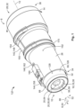
- Fig. 1 shows a perspective view of the electrical connector 1 according to one possible embodiment of the present disclosure.
- the electrical connector 1 may, in particular, be a high-voltage connector 2 e.g., for automotive applications.
- the electrical connector 1 is configured to be mated to a mating connector 4 (see Fig. 4 ), preferably along a mating direction 6.
- the electrical connector 1 comprises a housing assembly 8 and a core assembly 10, wherein the core assembly 10 is held rotatably within the housing assembly 8.
- the core assembly 10 is rotatable with respect to the housing assembly 8 about a rotational axis 12 parallel to said mating direction 6.
- the core assembly 10 may be rotatable with respect to the housing assembly 8 up to an angle of 360° or any multiple of 360° with an arbitrary integer.
- the core assembly 10 may be held fully and/or unrestrictedly rotatably within the housing assembly 8. This is indicated in Figs. 1 and 2 with arrows 14.
- the core assembly 10 comprises a contact assembly 16 with a contact 18 configured to electrically contact a mating contact (not shown) of the mating connector 4, a finger protection assembly 20 configured to at least partially cover the contact assembly 16, and a cable retention assembly 22 configured to be attached to an electrical cable 24.
- the housing assembly 8 may comprise a connector housing 26, through which a receptacle 28 extends along the mating direction 6 for receiving the electrical cable 24, preferably for receiving an end section 30 of the electrical cable 24. Further, the receptacle 28 may also be configured for receiving the core assembly 10. In particular, the receptacle 28 may be formed by a lead-through opening 32 extending through the connector housing 26. Thereby, the core assembly 10 is accessible to the mating connector 4 on one end 34 of the lead-through opening 32 and to the electrical cable 24 on the other end 36 of the lead-through opening 32.
- the contact 18 may be a turned, forged, cast or drawn contact element 38 made of copper or other electrically conductive material. Alternatively, the contact 18 may be a stamped and bent part. Further, the contact 18 may have a sleeve-shaped section 40 configured for electrical termination of the electrical cable 24. For example, the sleeve-shaped section 40 may be crimped onto an end section 42 of a conductor 44 of the electrical cable 24 (see Fig. 6 ). Alternatively, the sleeve-shaped section 40 may be soldered, welded or otherwise bonded to the end section 42 of the conductor 44.
- the contact 18 has a socket-shaped section 46 configured to receive and electrically contact a pin-shaped section (not shown) of the mating contact.
- the socket-shaped section 46 is positioned opposite to the sleeve-shaped section 40 with respect to the mating direction 6.
- the contact 18 may have a pin-shaped section configured to be inserted into a socket-shaped section of the mating contact, in order to establish electrical contacting therewith.
- the contact spring may optionally be arranged on the pin-shaped section of the contact.
- the finger protection assembly 20 may comprise an outer protection element 48 and a front protection element 50, which protect the contact 18 against unwanted touch by human fingers or other components besides the mating contact.
- the outer protection element 48 may surround the contact 18, in order to cover it in a radial direction 52 with respect to the mating direction 6, while the front protection element 50 may cover a front part 56 of the contact 18 in an axial direction 54, with respect to the mating direction.
- the front protection element 50 may cover a front end 58 of the contact 18 which extends towards the outside of the housing assembly 8.
- the outer protection element 48 and the front protection element 50 are monolithically connected to each other and form a protective collar 60 around the entire external surface 62 of the socket-shaped section 46 of the contact 18. Consequently, the front part 56 of the contact 18 may extend outwards of the housing assembly 8 and be covered by the protective collar 60.
- the protective collar 60 is also formed around the external surface of the sleeve-shaped section 40 of the contact 18. Accordingly, the socket-shaped section 46 and the sleeve-shaped section 40 of the contact 18 may be insertable into the protective collar 60.
- the protective collar 60 is press-fitted on the sleeve-shaped section 40 of the contact 18.
- the finger protection assembly 20 further comprises a spacer sleeve 61, which is insertable into the protective collar 60 after insertion of the contact 18.
- the spacer sleeve 61 is attached to the protective collar 60 by means of latching.
- the contact 18 is axially supported by the protective collar 60 and the spacer sleeve 61 from two opposing directions.
- the finger protection assembly 20 may further comprise an inner protection element 64 surrounded by the socket-shaped section 46 of the contact 18.
- the inner protection element 64 may be a cup-shaped or pillar-shaped body 66 inserted into the socket-shaped section 46 of the contact 18.
- the body 66 exhibits a cup-shaped segment 68 and a pillar-shaped segment 70.
- the front protection element may be a protective cap (not shown) attached to a tip of the pin-shaped section.
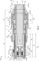
- the electrical connector may comprise a locking structure 72 which is configured to lock the core assembly 10 to the housing assembly 8, thereby blocking a translational relative movement between the core assembly 10 and the housing assembly 8.
- the locking structure 72 may comprise at least one pair of locking elements 74a, 74b that are in engagement with one another.
- One of the locking elements 74a may be, preferably continuous, a circumferential groove 76.
- the other one of the locking elements 74b may be at least one form-fit element 78, extending into the corresponding circumferential groove 76.
- the at least one form-fit element 78 may be formed on one of the housing assembly 8 and the core assembly 10. Accordingly, the corresponding circumferential groove 76 may be formed on the respective other one of the housing assembly 8 and core assembly 10.
- each circumferential groove 76 in the shown exemplary embodiment of Fig. 3 is formed on the housing assembly 8, while each form-fit element 58 is formed on the core assembly 10.
- the locking structure 72 comprises two pairs of locking elements 74a, 74b that are respectively in engagement with one another.
- two circumferential grooves 76a, 76b are formed on the housing assembly 8. More specifically, two circumferential grooves 76a, 76b are formed within the connector housing 26 adjacent to the receptacle 28.
- the core assembly 10 may further comprise a shield sleeve 80, in which the contact assembly 16 is at least partially received.
- the contact assembly 16 is entirely received in the shield sleeve 80.
- the finger protection assembly 20 and the cable retention assembly 22 are also entirely received in the shield sleeve 80.
- the cable retention assembly 22 is only partially received, while the contact assembly 16 and the finger protection assembly 20 are entirely received in the shield sleeve 80.
- the shield sleeve 80 may radially surround the contact 18 along the entire length 82 of the contact 18. Further, the shield sleeve 80 may be continuously spaced apart and insulated from the contact 18 by the outer protection element 48 of the finger protection assembly 20.
- the shield sleeve 80 may comprise at least one radially inwardly protruding section 84 engaging with one of the finger protection assembly 20 and the cable retention assembly 22.
- the at least one radially inwardly protruding section 84 may extend continuously or discontinuously around the shield sleeve 80 along a circumferential direction 86, with respect to the mating direction 6.
- the at least one radially inwardly protruding section 84 may be formed by a step, a flange, a shoulder or a taper 88 extending inwards of the shield sleeve 80.
- the at least one radially inwardly protruding section 84 may be formed by multiple latching tabs circumferentially distributed around the shield sleeve 80 and extending obliquely inwards of the shield sleeve.
- the shield sleeve 80 may further comprise at least one radially outwardly protruding section 90, engaging with the housing assembly 8.
- the at least one radially outwardly protruding section 90 may extend along the circumferential direction 86 around the shield sleeve 80 in a continuous or discontinuous manner.
- the at least one radially outwardly protruding section 90 may be formed by a step, a flange 92, a shoulder 94 or a taper extending outwards of the shield sleeve 80.
- the at least one radially outwardly protruding section 90 may be formed by multiple latching tabs 96, circumferentially distributed around the shield sleeve 80 and extending obliquely outwards of the shield sleeve 80.
- the shield sleeve 80 comprises one radially inwardly protruding section 84a in the form of the taper 88, for engaging with the finger protection assembly 20 and one radially inwardly protruding section 84b in the form of the taper 88, for engaging with the cable retention assembly 22.
- the shield sleeve 80 shown in Fig. 3 comprises one radially outwardly protruding section 90a in the form of the shoulder 94, one radially outwardly protruding section 90b in the form of the flange 92 and one radially outwardly protruding section 90c in the form of the multiple latching tabs 96.
- the flange 92 and the tabs 96 respectively engage with the housing assembly 8 in two mutually opposite directions.
- the shoulder 94 embodies the above-described form-fit element 78 and thus represents one of the locking elements 74b of the locking structure 72.
- the shoulder 94 extends into the circumferential groove 76a of the connector housing 26 as can be seen in Fig. 3 .
- the cable retention assembly 22 may comprise a cable fixation sleeve 98 configured to radially abut against a cable insulation 100 of the electrical cable 24.
- the cable fixation sleeve 98 may be sleeved over the end section 42 of the conductor 44, which is surrounded by the cable insulation 100.
- the cable fixation sleeve 98 may press radially against the cable insulation 100 and thus secure the electrical cable 24 in the axial direction 54.
- the cable fixation sleeve 98 may have a ring-shaped body 102 with a chamfered, barb-like circumferential bead 104.
- the circumferential bead 104 may be one of continuous and discontinuous and may extend into the circumferential groove 76b of the connector housing 26 as the at least one form-fit element 78.
- the chamfered property of the circumferential bead 104 facilitates the introduction into the corresponding circumferential groove 76b in an assembly direction 106.
- the barb-like property of the circumferential bead 104 prevents removal from the circumferential groove 76b in a direction opposite to the assembly direction 106.
- the cable fixation sleeve may comprise the circumferential groove as the locking element and the connector housing may comprise the circumferential bead as the other locking element, respectively.
- the cable retention assembly 22 may further comprise a shield support sleeve 108 configured to support a shield 110 of the electrical cable 24.
- the shield support sleeve 108 may radially support a contacting area 112 between the shield sleeve 80 and the shield 110 of the electrical cable 24.
- the shield support sleeve 108 provides a circumferential seating surface 114, on which the shield sleeve 80 and the shield 110 of the electrical cable 24 rest on top of each other.
- the shield support sleeve 108 is sleeved over the end section 30 of the electrical cable 24 and positioned under at least a layer of the shield 110 of the electrical cable 24.
- the shield 110 of the electrical cable 24 may be locally exposed, flared and rolled back over the shield support sleeve 108.
- the shield 110 of the electrical cable 24 may for example comprise a braid shield 110 and/or a foil shield, which is surrounded by the cable insulation 100.
- the shield 110 itself surrounds the conductor 44 of the electrical cable 24 and is spaced apart from the conductor 44 by an insulation layer 118 of the electrical cable 24.
- a difference between the outer diameter 120 of the shield support sleeve 108 and the inner diameter 122 of the shield sleeve 80 preferably allows the shield 110 of the electrical cable 24 to be sandwiched therebetween.
- a press-fit of the shield 110 between the shield sleeve 80 and the shield support sleeve 108 is even more preferable.
- the shield sleeve 80 may also be crimped onto the shield support sleeve 108.
- the shield support sleeve 108 may be arranged, preferably in the axial direction 54, between the cable fixation sleeve 98 and the finger protection assembly 20.
- the cable fixation sleeve 98, the shield support sleeve 108 and the finger protection assembly 20 may be coaxially aligned along the mating direction 6, as shown in Fig. 3 .
- the cable retention assembly 22 may comprise a sealing device 125 arranged between the cable fixation sleeve 98 and the shield support sleeve 108.
- the sealing device 125 comprises at least one sealing element 124, preferably having an annular shape, arranged between the cable fixation sleeve 98 and the shield support sleeve 108.
- the at least one sealing element 124 may radially abut against the shield sleeve 80 and the cable insulation 100, thus preventing moisture and/or dirt from passing through a gap between the shield sleeve 80 and the electrical cable 24.
- the at least one sealing element 124 may directly abut against the housing assembly 8, instead of the shield sleeve 80.
- the sealing device 125 comprises two sealing elements 124 and a seal support sleeve 123 with a higher rigidity than the two sealing elements 124.
- the seal support sleeve 123 is positioned between the cable fixation sleeve 98 and the shield support sleeve 108 to axially abut against the cable fixation sleeve 98 and the shield support sleeve 108, respectively.
- the two sealing elements 124 are arranged between the abutment area of the seal support sleeve 123 with the cable fixation sleeve 98 and the abutment area of the seal support sleeve 123 with the shield support sleeve 108.
- the two sealing elements 124 are arranged on opposite surfaces of the seal support sleeve 123.
- one of the two sealing elements 124 radially abuts against the seal support sleeve 123 and the housing assembly 8, while being positioned on an outer circumferential surface of the seal support sleeve 123 in a circumferential seal reception notch 121 formed on the outer circumferential surface of the seal support sleeve 123.
- the other one of the two sealing elements 124 is positioned on an inner circumferential surface of the seal support sleeve 123, while radially abutting against the seal support sleeve123 and the cable insulation 100.
- the cable fixation sleeve and the shield support sleeve may be monolithically connected with the seal support sleeve 123 of the sealing device 125 to form a single, sleeve-shaped component.
- the outer protection element 48 of the finger protection assembly 20 may be axially supported by the shield sleeve 80 and the cable retention assembly 22 from two opposing directions. This can be seen in the sectional view of Fig. 3 , where the outer protection element 48 abuts axially against the taper 88 of the shield sleeve 80, while also axially abutting against the shield 110 of the electrical cable 24 folded over the shield support sleeve 108 of the cable retention assembly 22.
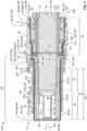
- the outer protection element 48 of the finger protection assembly 20 may be axially supported by the housing assembly 8 and the cable retention assembly 22 from two opposing directions, as shown in the embodiment of Fig. 6 .
- the housing assembly 8 in particular the connector housing 26, comprises an inward protrusion 29 forming a circumferential internal shoulder 25a at a front section 31 of the connector housing 26, the front section 31 of the connector housing 26 being situated adjacent to the front part 56 of the contact 18.
- the outer protection element 48 and the spacer sleeve 61 both abut axially against the shield 110 of the electrical cable 24 folded over the shield support sleeve 108 of the cable retention assembly 22.
- the housing assembly 8 may comprise a housing lid 27 in addition to the connector housing 26.
- the housing lid 27 may be a substantially hollow cylindrical structure sleeved over the electrical cable 24. Further, the housing lid 27 may at least partly encompass a rear section 33 of the connector housing 26, the rear section 33 of the connector housing 26 being situated opposite of the front section 31 of the connector housing 26 with respect to the mating direction 6.
- the housing lid 27 may be attached to the connector housing 26 along the mating direction 6 after insertion of the core assembly 10 into the receptacle 28 of the connector housing 26.
- the housing lid 27 is connected to the connector housing 26 by means of latching. Alternatively, clipping, gluing, welding and/or screws may be utilized.
- FIG. 6 The sectional view of Fig. 6 clearly shows how the connector housing 26 and housing lid 27 cooperate to hold captive the core assembly 10.
- the core assembly 10 is locked to the housing assembly 8 by means of the circumferential internal shoulder 25a of the connector housing 26 and another circumferential internal shoulder 25b formed on the housing lid 27 distal from the circumferential internal shoulder 25a of the connector housing 26.
- the circumferential shoulders 25a, 25b axially support the core assembly 10 from two opposing directions.
- the housing lid 27 may comprise a conical inner surface 35 having a smallest diameter 39 and widening in the mating direction 6, as shown in Fig. 6 .
- the cable fixation sleeve 98 may comprise a conical outer surfaces 37 having a biggest diameter 41 and widening in the mating direction 6.
- the smallest diameter 39 of the conical inner surface 35 is smaller than the biggest diameter 41 of the conical outer surface 37 such that these conical surfaces 35, 37 slide along each other, when attaching the housing lid 27 to the connector housing 26. Thereby, the radial pressure of the cable fixation sleeve 98 exerted onto the cable insulation 100 is gradually increased.
- the shield sleeve 80 may form an outer hull 126 of the core assembly 10.
- the shield sleeve 80 may provide an external bearing surface 128 for relative rotational movement between the core assembly 10 and the housing assembly 8.
- the shield sleeve 80 may provide an internal bearing surface 130 for relative rotational movement between the shield sleeve 80 and the contact assembly 16, the finger protection assembly 20 as well as the cable retention assembly 22.
- the internal and/or external bearing surfaces 128, 130 are rotationally symmetric with respect to the rotational axis 12, respectively.
- the receptacle may have an inner surface 132, which is rotationally symmetric with respect to the rotational axis 12.
- the contact 18, the outer protection element 48, the inner protection element 64, the front protection element 50, the cable fixation sleeve 98, the shield support sleeve 108 and/or the at least one sealing element 124 may be rotationally symmetric with respect to the rotational axis 12.
- a front section of the shield sleeve 80 may stick out of the housing assembly 8 and be configured for contacting a grounding contact (not shown) of the mating connector 4.
- a grounding contact (not shown) of the mating connector 4.
- at least one access slit 43 preferably multiple access slits 43 are provided on the housing assembly 8 to allow the grounding contact access to the shield sleeve 80. This will be described in further detail below.
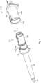
- the electrical connector 1 is shown together with an exemplary embodiment of the mating connector 4 in a ready-to-mate position.
- the mating connector 4 is shown as a socket 134 with a female connector face 136 configured to at least partially receive the electrical connector 1 along the mating direction 6.
- the mating contact (not shown) is arranged and accessible to the contact 18 of the electrical connector 1 upon mating.
- the connector housing 26 of the electrical connector 1 has an outer contour 138 which is rotationally asymmetric, with respect to the rotational axis 12.
- the female connector face 136 of the mating connector 4 has an inner contour 140 which is complementary to the outer contour 138.
- a certain relative angular orientation between the connector housing 26 and the female connector face 136 is required for mating the electrical connector 1 with the mating connector 4. Due to the above-described rotatably of the housing assembly 8 in general and the connector housing 26 in particular, the connector housing 26 can be oriented in the correct angular orientation with respect to the mating connector 4, without having to twist or otherwise rotate the electrical cable 24.
- the rotationally asymmetric outer contour 138 of the connector housing 26 may derive from at least one of a rotationally asymmetric locking feature 142, a rotationally asymmetric coding feature 144 and a rotationally asymmetric in the arranged circuitry element 146.
- the connector housing 26 comprises one of each of these features 142, 144, 146.
- the mating connector comprises complementarily features (not shown) for interaction with the features 142, 144, 146.
- the locking feature 142 may be a mechanical structure, such as a cantilever tab 148, for securing the connector housing 26 to the mating connector 4.
- the cantilever tab 148 may have a supported end 150 connected to the external surface 152 of the connector housing 26 and a free end 154 which extends obliquely away from the external surface 152, while pointing in or against the mating direction 6.
- the free end 154 may be configured to axially abut against an inner edge (not shown) formed within the female connector face 136 of the mating connector 4.
- the mating connector 4 may comprise an unlocking slider 156, for pushing the free end 154 out of abutment with the inner edge and thereby releasing the connector housing 26 from the mating connector 4.
- the coding feature 144 may be a mechanical structure, such as an axial fin 158, defining a certain relative angular orientation between the connector housing 26 and the mating connector 4, which is required for mating.
- the axial fin 158 may extend along the external surface 152 of the connector housing 26 in the mating direction 6.
- a slot (not shown) shaped complementarily to the axial fin 158 may be formed within the female connector face 136 of the mating connector 4 and configured to receive the axial fin 158.
- the coding feature 144 may also be utilized to prevent a mix-up of connectors by only allowing mating of the matching pairs according to a key-lock principle.
- the circuitry element 146 may be integrated in a circuitry container 160 formed on the external surface 152 of the connector housing 26.
- the mating connector 4 may comprise an open circuitry (not shown) of a monitoring circuit 162, wherein the circuitry element 146 may be a part of the monitoring circuit 162 which is configured for closing said open circuitry upon mating.
- the monitoring circuit 162 may, in particular, be a high-voltage interlock circuit for detecting a mated state as well as an unmated state of the electrical connector 1 and mating connector 4.
- the rotationally asymmetric outer contour 138 of the connector housing 26 may also derive from at least one rotationally asymmetric grounding feature 145.
- the grounding feature 145 may be the above-introduced at least one access slit 43.
- multiple such access slits 43 are formed by substantially rectangular, lateral slots 45 in the connector housing 26 extending along the mating direction 6 at overlapping positions with the shield sleeve 80. Through these access slits 43, the grounding contact of the mating connector 4 can pass and reach the shield sleeve 80 for grounding purposes. Further sealing elements may be provided in and on the electrical connector 1.
- one of the radially outwardly protruding section 90 and radially inwardly protruding section 84 of the shield sleeve 80 may provide a seat 164 for receiving a first additional sealing element 166 in the form of a seal ring 168.
- a second additional sealing element 170 may be provided on the external surface 152 of the connector housing 26.
- the second additional sealing element 170 may comprise an external sealing surface 172 which is configured to seal a gap between the connector housing 26 and the female connector face 136 of the mating connector.
- the external sealing surface 172 may extend outwards of the circuitry element 146, with respect to the receptacle 28. This is best shown in Fig. 2 , where for each point on the outer surface of the circuitry element 146 a point on the external sealing surface 172 exist, which has a greater distance from the receptacle 28.
Landscapes
- Details Of Connecting Devices For Male And Female Coupling (AREA)
Claims (12)
- Elektrischer Verbinder (1), der so konfiguriert ist, dass er mit einem Gegenverbinder (4) verbunden werden kann, wobei der elektrische Verbinder (1) eine Gehäuseanordnung (8) und eine Kernbaugruppe (10) umfasst, wobei die Kernbaugruppe (10) aufweist:eine Kontaktanordnung (16) mit einem Kontakt (18), der so konfiguriert ist, dass er einen Gegenkontakt des Gegenverbinders (4) elektrisch kontaktiert,eine Fingerschutzbaugruppe (20), die so konfiguriert ist, dass sie die Kontaktanordnung (16) zumindest teilweise abdeckt, undeine Kabelhaltebaugruppe (22), die so konfiguriert ist, dass sie an einem elektrischen Kabel (24) angebracht werden kann,wobei die Kernbaugruppe (10) drehbar in der Gehäusebaugruppe (8) gehalten wird, wobei die Kabelhaltebaugruppe (22) eine Kabelfixierhülse (98), die so konfiguriert ist, dass sie radial an einer Kabelisolierung (100) des elektrischen Kabels (24) anliegt, und eine Abschirmungsstützhülse (108) umfasst, die so konfiguriert ist, dass sie eine Abschirmung (110) des elektrischen Kabels (24) stützt, dadurch gekennzeichnet, dass die Kabelhaltebaugruppe (22) ferner eine Dichtungsvorrichtung (125) umfasst, die zwischen der Kabelfixierhülse (98) und der Abschirmungsstützhülse (108) angeordnet ist.
- Elektrischer Verbinder (1) gemäß Anspruch 1, wobei die Fingerschutzbaugruppe (20) ein äußeres Schutzelement (48) und ein vorderes Schutzelement (50) umfasst, wobei das äußere Schutzelement (48) den Kontakt (18) umgibt und das vordere Schutzelement (50) einen vorderen Teil (56) des Kontakts (18) abdeckt.
- Elektrischer Verbinder (1) nach Anspruch 1 oder 2, wobei der elektrische Verbinder (1) eine Verriegelungsstruktur (72) umfasst, die so konfiguriert ist, dass sie die Kernbaugruppe (10) an der Gehäusebaugruppe (8) verriegelt und eine translatorische Relativbewegung zwischen der Kernbaugruppe (10) und der Gehäusebaugruppe (8) blockiert.
- Elektrischer Verbinder (1) nach Anspruch 3, wobei die Verriegelungsstruktur (72) mindestens ein Paar Verriegelungselemente (74a, 74b) umfasst, die miteinander in Eingriff stehen, wobei eines der Verriegelungselemente (74a) eine Umfangsnut (76, 76a, 76b) ist und das andere der Verriegelungselemente (74b) mindestens ein Formschlusselement (78) ist, das sich in die entsprechende Umfangsnut (76, 76a, 76b) erstreckt, wobei das mindestens eine Formschlusselement (78) an einem von Gehäusebaugruppe (8) und Kernbaugruppe (10) ausgebildet ist und wobei die entsprechende Umfangsnut (76, 76a, 76b) an dem anderen von Gehäusebaugruppe (8) und Kernbaugruppe (10) ausgebildet ist.
- Elektrischer Verbinder (1) nach Anspruch 4, wobei das Verriegelungselement (74a, 74b) der Kernbaugruppe (10) an der Kabelhaltebaugruppe (22) angeordnet ist.
- Elektrischer Verbinder (1) nach einem der Ansprüche 1 bis 5, wobei die Kernbaugruppe (10) eine Abschirmhülse (80) umfasst, in der die Kontaktanordnung (16), die Fingerschutzbaugruppe (20) und die Kabelhaltebaugruppe (22) zumindest teilweise aufgenommen sind.
- Elektrischer Verbinder (1) nach Anspruch 6, wobei die Abschirmhülse (80) mindestens einen radial nach innen vorstehenden Abschnitt (84, 84a, 84b) umfasst, der mit einem der Fingerschutzbaugruppe (20) und der Kabelhaltebaugruppe (22) in Eingriff steht.
- Elektrischer Verbinder (1) nach Anspruch 6 oder 7, wobei die Abschirmhülse (80) mindestens einen radial nach außen vorstehenden Abschnitt (90, 90a, 90b, 90c) umfasst, der mit der Gehäuseanordnung (8) in Eingriff steht.
- Elektrischer Verbinder (1) nach einem der Ansprüche 6 bis 8, wobei die Abschirmhülse (80) eine äußere Hülle (126) der Kernbaugruppe (10) bildet.
- Elektrischer Verbinder (1) nach Anspruch 1, wobei die Abschirmungsstützhülse (108) zwischen der Kabelfixierhülse (98) und der Fingerschutzbaugruppe (20) angeordnet ist.
- Elektrischer Verbinder (1) gemäß einem der Ansprüche 1 bis 10, wobei die Gehäuseanordnung (8) ein Verbindergehäuse (26) umfasst, durch das sich eine Aufnahme (28) zum Aufnehmen des elektrischen Kabels (24) entlang einer Steckrichtung (6) erstreckt, und wobei das Verbindergehäuse (26) eine rotationsasymmetrische Außenkontur (138) in Bezug auf die Steckrichtung (6) aufweist.
- Elektrischer Verbinder (1) nach Anspruch 11, wobei die rotationsasymmetrische Außenkontur (138) des Verbindergehäuses (26) von mindestens einem rotationsasymmetrischen Verriegelungsmerkmal (142), einem rotationsasymmetrischen Kodiermerkmal (144), einem rotationsasymmetrischen Erdungsmerkmal (145) und einem rotationsasymmetrisch angeordneten Schaltungselement (146) abgeleitet ist.
Priority Applications (3)
| Application Number | Priority Date | Filing Date | Title |
|---|---|---|---|
| EP20199634.5A EP3979428B1 (de) | 2020-10-01 | 2020-10-01 | Elektrischer verbinder mit minimaler übertragung der torsionsbelastung |
| US17/463,674 US11923637B2 (en) | 2020-10-01 | 2021-09-01 | Electrical connector with minimal transfer of torsional load |
| CN202111140937.5A CN114267977B (zh) | 2020-10-01 | 2021-09-28 | 具有最小扭转载荷传递的电连接器 |
Applications Claiming Priority (1)
| Application Number | Priority Date | Filing Date | Title |
|---|---|---|---|
| EP20199634.5A EP3979428B1 (de) | 2020-10-01 | 2020-10-01 | Elektrischer verbinder mit minimaler übertragung der torsionsbelastung |
Publications (2)
| Publication Number | Publication Date |
|---|---|
| EP3979428A1 EP3979428A1 (de) | 2022-04-06 |
| EP3979428B1 true EP3979428B1 (de) | 2025-04-09 |
Family
ID=72717775
Family Applications (1)
| Application Number | Title | Priority Date | Filing Date |
|---|---|---|---|
| EP20199634.5A Active EP3979428B1 (de) | 2020-10-01 | 2020-10-01 | Elektrischer verbinder mit minimaler übertragung der torsionsbelastung |
Country Status (3)
| Country | Link |
|---|---|
| US (1) | US11923637B2 (de) |
| EP (1) | EP3979428B1 (de) |
| CN (1) | CN114267977B (de) |
Families Citing this family (6)
| Publication number | Priority date | Publication date | Assignee | Title |
|---|---|---|---|---|
| EP4387008A1 (de) * | 2022-12-16 | 2024-06-19 | Aptiv Technologies AG | Hochspannungsverbinder und verfahren zur bereitstellung einer hochspannungsverbindung |
| CN115967211A (zh) * | 2023-02-14 | 2023-04-14 | 蔚来动力科技(合肥)有限公司 | 电机定子及电机 |
| DE102023108963A1 (de) * | 2023-04-06 | 2024-10-10 | Te Connectivity Solutions Gmbh | Hochstromverbinder für ein elektrisches Fahrzeug |
| WO2025005918A1 (en) * | 2023-06-29 | 2025-01-02 | Itt Cannon Gmbh | Sensor connector with bayonet coupling |
| WO2025172071A1 (en) * | 2024-02-13 | 2025-08-21 | Huber+Suhner Ag | Plug connector |
| DE102024106165A1 (de) * | 2024-03-04 | 2025-09-04 | Te Connectivity Solutions Gmbh | Gehäuseanordnung für einen elektrischen Steckverbinder |
Citations (1)
| Publication number | Priority date | Publication date | Assignee | Title |
|---|---|---|---|---|
| US20190013626A1 (en) * | 2015-12-21 | 2019-01-10 | Amphenol Tuchel Electronics Gmbh | Shielded plug connection assembly |
Family Cites Families (16)
| Publication number | Priority date | Publication date | Assignee | Title |
|---|---|---|---|---|
| US4280749A (en) * | 1979-10-25 | 1981-07-28 | The Bendix Corporation | Socket and pin contacts for coaxial cable |
| JP3670495B2 (ja) * | 1998-11-09 | 2005-07-13 | 矢崎総業株式会社 | 端子 |
| JP2000171724A (ja) * | 1998-12-04 | 2000-06-23 | Olympus Optical Co Ltd | 電気的コネクタ |
| US6332815B1 (en) * | 1999-12-10 | 2001-12-25 | Litton Systems, Inc. | Clip ring for an electrical connector |
| GB2469487B (en) * | 2009-04-15 | 2012-08-15 | Tyco Electronics Ltd Uk | Coaxial cable connector and associated method |
| JP5375440B2 (ja) * | 2009-08-26 | 2013-12-25 | 住友電装株式会社 | 雄型コネクタ及びコネクタ装置 |
| US7980894B1 (en) * | 2010-08-23 | 2011-07-19 | Tyco Electronics Corporation | Coaxial connector with a cable receptor with an outer contact |
| US8734191B2 (en) * | 2011-10-06 | 2014-05-27 | Tyco Electronics Corporation | Power connector system |
| DK2777097T3 (da) * | 2011-11-10 | 2019-11-18 | Hirschmann Automation & Control Gmbh | Skærmet stikforbindelse og fremgangsmåde til fremstilling af en skærmet stikforbindelse |
| DE102013209690B4 (de) * | 2013-05-24 | 2023-08-03 | Te Connectivity Germany Gmbh | HV-Fingerschutz |
| US9837761B1 (en) * | 2016-09-22 | 2017-12-05 | Te Connectivity Corporation | Electrical cable connector with rotatable housing |
| EP3389146B1 (de) * | 2017-04-11 | 2020-08-05 | Yazaki Europe Ltd. | Elektrische verbinderanordnung |
| JP6913524B2 (ja) * | 2017-06-14 | 2021-08-04 | モレックス エルエルシー | 同軸コネクタ |
| DE102017210425A1 (de) * | 2017-06-21 | 2018-12-27 | Te Connectivity Germany Gmbh | Modulverbinder |
| JP6386138B1 (ja) * | 2017-07-14 | 2018-09-05 | 日本航空電子工業株式会社 | コネクタ |
| CN110197965B (zh) * | 2019-06-03 | 2024-01-19 | 核工业理化工程研究院 | 应用于30kV高压设备系统中带屏蔽和自锁功能的电连接器 |
-
2020
- 2020-10-01 EP EP20199634.5A patent/EP3979428B1/de active Active
-
2021
- 2021-09-01 US US17/463,674 patent/US11923637B2/en active Active
- 2021-09-28 CN CN202111140937.5A patent/CN114267977B/zh active Active
Patent Citations (1)
| Publication number | Priority date | Publication date | Assignee | Title |
|---|---|---|---|---|
| US20190013626A1 (en) * | 2015-12-21 | 2019-01-10 | Amphenol Tuchel Electronics Gmbh | Shielded plug connection assembly |
Also Published As
| Publication number | Publication date |
|---|---|
| CN114267977A (zh) | 2022-04-01 |
| US20220109270A1 (en) | 2022-04-07 |
| EP3979428A1 (de) | 2022-04-06 |
| US11923637B2 (en) | 2024-03-05 |
| CN114267977B (zh) | 2025-02-18 |
Similar Documents
| Publication | Publication Date | Title |
|---|---|---|
| EP3979428B1 (de) | Elektrischer verbinder mit minimaler übertragung der torsionsbelastung | |
| EP2415128B1 (de) | Koaxialverbinder mit innerer abschirmanordnung und verfahren zum zusammenbau eines solchen | |
| EP2681808B1 (de) | Verbinder mit gehäuse mit abstandshalter mit einem projektionspaar | |
| JP5808043B2 (ja) | 同軸ケーブルコネクタ | |
| US11664629B2 (en) | Assembly comprising a connector and a cable | |
| US20230223724A1 (en) | Contact member for electrical connector | |
| EP3203586B1 (de) | Elektrischer steckverbinder | |
| US11411352B2 (en) | Connector for automotive applications | |
| EP2419967A1 (de) | Coaxialverbinder und verfahren zum zusammenbau eines solchen | |
| US11462861B2 (en) | Electrical shielding member for a network connector | |
| WO2016126515A1 (en) | Right angle coaxial cable and connector assembly | |
| US20020039853A1 (en) | Connector | |
| CN117438815A (zh) | 屏蔽弹簧触头、插入式连接器和插入式连接器系统 | |
| US20090318020A1 (en) | Adapter for a coaxial cable connector | |
| US10784628B2 (en) | Electrical plug connector | |
| JP2025158082A (ja) | シールドコネクタ | |
| HK1024343A (en) | An electrical connector and earthing element |
Legal Events
| Date | Code | Title | Description |
|---|---|---|---|
| PUAI | Public reference made under article 153(3) epc to a published international application that has entered the european phase |
Free format text: ORIGINAL CODE: 0009012 |
|
| STAA | Information on the status of an ep patent application or granted ep patent |
Free format text: STATUS: THE APPLICATION HAS BEEN PUBLISHED |
|
| AK | Designated contracting states |
Kind code of ref document: A1 Designated state(s): AL AT BE BG CH CY CZ DE DK EE ES FI FR GB GR HR HU IE IS IT LI LT LU LV MC MK MT NL NO PL PT RO RS SE SI SK SM TR |
|
| STAA | Information on the status of an ep patent application or granted ep patent |
Free format text: STATUS: REQUEST FOR EXAMINATION WAS MADE |
|
| 17P | Request for examination filed |
Effective date: 20220930 |
|
| RBV | Designated contracting states (corrected) |
Designated state(s): AL AT BE BG CH CY CZ DE DK EE ES FI FR GB GR HR HU IE IS IT LI LT LU LV MC MK MT NL NO PL PT RO RS SE SI SK SM TR |
|
| RIN1 | Information on inventor provided before grant (corrected) |
Inventor name: SCHIEMER, BJOEM Inventor name: DOMKE, DANIEL Inventor name: BISCHOFF, DANIEL |
|
| STAA | Information on the status of an ep patent application or granted ep patent |
Free format text: STATUS: EXAMINATION IS IN PROGRESS |
|
| 17Q | First examination report despatched |
Effective date: 20240130 |
|
| RIC1 | Information provided on ipc code assigned before grant |
Ipc: H01R 101/00 20060101ALN20241010BHEP Ipc: H01R 24/42 20110101ALN20241010BHEP Ipc: H01R 24/00 20110101ALN20241010BHEP Ipc: H01R 24/38 20110101ALI20241010BHEP Ipc: H01R 13/648 20060101ALI20241010BHEP Ipc: H01R 13/516 20060101ALI20241010BHEP Ipc: H01R 13/434 20060101AFI20241010BHEP |
|
| GRAP | Despatch of communication of intention to grant a patent |
Free format text: ORIGINAL CODE: EPIDOSNIGR1 |
|
| STAA | Information on the status of an ep patent application or granted ep patent |
Free format text: STATUS: GRANT OF PATENT IS INTENDED |
|
| RIC1 | Information provided on ipc code assigned before grant |
Ipc: H01R 101/00 20060101ALN20241022BHEP Ipc: H01R 24/42 20110101ALN20241022BHEP Ipc: H01R 24/00 20110101ALN20241022BHEP Ipc: H01R 24/38 20110101ALI20241022BHEP Ipc: H01R 13/648 20060101ALI20241022BHEP Ipc: H01R 13/516 20060101ALI20241022BHEP Ipc: H01R 13/434 20060101AFI20241022BHEP |
|
| RIC1 | Information provided on ipc code assigned before grant |
Ipc: H01R 101/00 20060101ALN20241106BHEP Ipc: H01R 24/42 20110101ALN20241106BHEP Ipc: H01R 24/00 20110101ALN20241106BHEP Ipc: H01R 24/38 20110101ALI20241106BHEP Ipc: H01R 13/648 20060101ALI20241106BHEP Ipc: H01R 13/516 20060101ALI20241106BHEP Ipc: H01R 13/434 20060101AFI20241106BHEP |
|
| INTG | Intention to grant announced |
Effective date: 20241119 |
|
| RIN1 | Information on inventor provided before grant (corrected) |
Inventor name: SCHIEMER, BJOERN Inventor name: DOMKE, DANIEL Inventor name: BISCHOFF, DANIEL |
|
| GRAS | Grant fee paid |
Free format text: ORIGINAL CODE: EPIDOSNIGR3 |
|
| GRAA | (expected) grant |
Free format text: ORIGINAL CODE: 0009210 |
|
| STAA | Information on the status of an ep patent application or granted ep patent |
Free format text: STATUS: THE PATENT HAS BEEN GRANTED |
|
| AK | Designated contracting states |
Kind code of ref document: B1 Designated state(s): AL AT BE BG CH CY CZ DE DK EE ES FI FR GB GR HR HU IE IS IT LI LT LU LV MC MK MT NL NO PL PT RO RS SE SI SK SM TR |
|
| REG | Reference to a national code |
Ref country code: GB Ref legal event code: FG4D |
|
| RIN1 | Information on inventor provided before grant (corrected) |
Inventor name: SCHIEMER, BJOERN Inventor name: DOMKE, DANIEL Inventor name: BISCHOFF, DANIEL |
|
| REG | Reference to a national code |
Ref country code: CH Ref legal event code: EP |
|
| REG | Reference to a national code |
Ref country code: DE Ref legal event code: R096 Ref document number: 602020049015 Country of ref document: DE |
|
| REG | Reference to a national code |
Ref country code: IE Ref legal event code: FG4D |
|
| REG | Reference to a national code |
Ref country code: NL Ref legal event code: MP Effective date: 20250409 |
|
| PG25 | Lapsed in a contracting state [announced via postgrant information from national office to epo] |
Ref country code: NL Free format text: LAPSE BECAUSE OF FAILURE TO SUBMIT A TRANSLATION OF THE DESCRIPTION OR TO PAY THE FEE WITHIN THE PRESCRIBED TIME-LIMIT Effective date: 20250409 |
|
| REG | Reference to a national code |
Ref country code: AT Ref legal event code: MK05 Ref document number: 1784428 Country of ref document: AT Kind code of ref document: T Effective date: 20250409 |
|
| PG25 | Lapsed in a contracting state [announced via postgrant information from national office to epo] |
Ref country code: FI Free format text: LAPSE BECAUSE OF FAILURE TO SUBMIT A TRANSLATION OF THE DESCRIPTION OR TO PAY THE FEE WITHIN THE PRESCRIBED TIME-LIMIT Effective date: 20250409 Ref country code: ES Free format text: LAPSE BECAUSE OF FAILURE TO SUBMIT A TRANSLATION OF THE DESCRIPTION OR TO PAY THE FEE WITHIN THE PRESCRIBED TIME-LIMIT Effective date: 20250409 Ref country code: PT Free format text: LAPSE BECAUSE OF FAILURE TO SUBMIT A TRANSLATION OF THE DESCRIPTION OR TO PAY THE FEE WITHIN THE PRESCRIBED TIME-LIMIT Effective date: 20250811 |
|
| REG | Reference to a national code |
Ref country code: LT Ref legal event code: MG9D |
|
| PG25 | Lapsed in a contracting state [announced via postgrant information from national office to epo] |
Ref country code: NO Free format text: LAPSE BECAUSE OF FAILURE TO SUBMIT A TRANSLATION OF THE DESCRIPTION OR TO PAY THE FEE WITHIN THE PRESCRIBED TIME-LIMIT Effective date: 20250709 Ref country code: GR Free format text: LAPSE BECAUSE OF FAILURE TO SUBMIT A TRANSLATION OF THE DESCRIPTION OR TO PAY THE FEE WITHIN THE PRESCRIBED TIME-LIMIT Effective date: 20250710 |
|
| PG25 | Lapsed in a contracting state [announced via postgrant information from national office to epo] |
Ref country code: PL Free format text: LAPSE BECAUSE OF FAILURE TO SUBMIT A TRANSLATION OF THE DESCRIPTION OR TO PAY THE FEE WITHIN THE PRESCRIBED TIME-LIMIT Effective date: 20250409 |
|
| PG25 | Lapsed in a contracting state [announced via postgrant information from national office to epo] |
Ref country code: BG Free format text: LAPSE BECAUSE OF FAILURE TO SUBMIT A TRANSLATION OF THE DESCRIPTION OR TO PAY THE FEE WITHIN THE PRESCRIBED TIME-LIMIT Effective date: 20250409 |
|
| PGFP | Annual fee paid to national office [announced via postgrant information from national office to epo] |
Ref country code: GB Payment date: 20250904 Year of fee payment: 6 |
|
| PG25 | Lapsed in a contracting state [announced via postgrant information from national office to epo] |
Ref country code: HR Free format text: LAPSE BECAUSE OF FAILURE TO SUBMIT A TRANSLATION OF THE DESCRIPTION OR TO PAY THE FEE WITHIN THE PRESCRIBED TIME-LIMIT Effective date: 20250409 |
|
| PG25 | Lapsed in a contracting state [announced via postgrant information from national office to epo] |
Ref country code: AT Free format text: LAPSE BECAUSE OF FAILURE TO SUBMIT A TRANSLATION OF THE DESCRIPTION OR TO PAY THE FEE WITHIN THE PRESCRIBED TIME-LIMIT Effective date: 20250409 |
|
| PGFP | Annual fee paid to national office [announced via postgrant information from national office to epo] |
Ref country code: FR Payment date: 20250908 Year of fee payment: 6 |
|
| PG25 | Lapsed in a contracting state [announced via postgrant information from national office to epo] |
Ref country code: RS Free format text: LAPSE BECAUSE OF FAILURE TO SUBMIT A TRANSLATION OF THE DESCRIPTION OR TO PAY THE FEE WITHIN THE PRESCRIBED TIME-LIMIT Effective date: 20250709 |
|
| PG25 | Lapsed in a contracting state [announced via postgrant information from national office to epo] |
Ref country code: IS Free format text: LAPSE BECAUSE OF FAILURE TO SUBMIT A TRANSLATION OF THE DESCRIPTION OR TO PAY THE FEE WITHIN THE PRESCRIBED TIME-LIMIT Effective date: 20250809 |
|
| PG25 | Lapsed in a contracting state [announced via postgrant information from national office to epo] |
Ref country code: LV Free format text: LAPSE BECAUSE OF FAILURE TO SUBMIT A TRANSLATION OF THE DESCRIPTION OR TO PAY THE FEE WITHIN THE PRESCRIBED TIME-LIMIT Effective date: 20250409 |
|
| PGFP | Annual fee paid to national office [announced via postgrant information from national office to epo] |
Ref country code: DE Payment date: 20250902 Year of fee payment: 6 |
|
| REG | Reference to a national code |
Ref country code: DE Ref legal event code: R097 Ref document number: 602020049015 Country of ref document: DE |
|
| PG25 | Lapsed in a contracting state [announced via postgrant information from national office to epo] |
Ref country code: DK Free format text: LAPSE BECAUSE OF FAILURE TO SUBMIT A TRANSLATION OF THE DESCRIPTION OR TO PAY THE FEE WITHIN THE PRESCRIBED TIME-LIMIT Effective date: 20250409 Ref country code: SM Free format text: LAPSE BECAUSE OF FAILURE TO SUBMIT A TRANSLATION OF THE DESCRIPTION OR TO PAY THE FEE WITHIN THE PRESCRIBED TIME-LIMIT Effective date: 20250409 |
|
| PG25 | Lapsed in a contracting state [announced via postgrant information from national office to epo] |
Ref country code: CZ Free format text: LAPSE BECAUSE OF FAILURE TO SUBMIT A TRANSLATION OF THE DESCRIPTION OR TO PAY THE FEE WITHIN THE PRESCRIBED TIME-LIMIT Effective date: 20250409 |
|
| PG25 | Lapsed in a contracting state [announced via postgrant information from national office to epo] |
Ref country code: EE Free format text: LAPSE BECAUSE OF FAILURE TO SUBMIT A TRANSLATION OF THE DESCRIPTION OR TO PAY THE FEE WITHIN THE PRESCRIBED TIME-LIMIT Effective date: 20250409 |
|
| PG25 | Lapsed in a contracting state [announced via postgrant information from national office to epo] |
Ref country code: SK Free format text: LAPSE BECAUSE OF FAILURE TO SUBMIT A TRANSLATION OF THE DESCRIPTION OR TO PAY THE FEE WITHIN THE PRESCRIBED TIME-LIMIT Effective date: 20250409 Ref country code: RO Free format text: LAPSE BECAUSE OF FAILURE TO SUBMIT A TRANSLATION OF THE DESCRIPTION OR TO PAY THE FEE WITHIN THE PRESCRIBED TIME-LIMIT Effective date: 20250409 |
|
| PG25 | Lapsed in a contracting state [announced via postgrant information from national office to epo] |
Ref country code: IT Free format text: LAPSE BECAUSE OF FAILURE TO SUBMIT A TRANSLATION OF THE DESCRIPTION OR TO PAY THE FEE WITHIN THE PRESCRIBED TIME-LIMIT Effective date: 20250409 |
|
| PLBE | No opposition filed within time limit |
Free format text: ORIGINAL CODE: 0009261 |
|
| STAA | Information on the status of an ep patent application or granted ep patent |
Free format text: STATUS: NO OPPOSITION FILED WITHIN TIME LIMIT |
|
| REG | Reference to a national code |
Ref country code: CH Ref legal event code: L10 Free format text: ST27 STATUS EVENT CODE: U-0-0-L10-L00 (AS PROVIDED BY THE NATIONAL OFFICE) Effective date: 20260218 |
|
| 26N | No opposition filed |
Effective date: 20260112 |