EP3979397A1 - Positive electrode plate and electrochemical device and equipment associated therewith - Google Patents
Positive electrode plate and electrochemical device and equipment associated therewith Download PDFInfo
- Publication number
- EP3979397A1 EP3979397A1 EP20849080.5A EP20849080A EP3979397A1 EP 3979397 A1 EP3979397 A1 EP 3979397A1 EP 20849080 A EP20849080 A EP 20849080A EP 3979397 A1 EP3979397 A1 EP 3979397A1
- Authority
- EP
- European Patent Office
- Prior art keywords
- positive electrode
- derivatives
- electrode plate
- phosphate
- carbonate
- Prior art date
- Legal status (The legal status is an assumption and is not a legal conclusion. Google has not performed a legal analysis and makes no representation as to the accuracy of the status listed.)
- Granted
Links
Images

Classifications
-
- H—ELECTRICITY
- H01—ELECTRIC ELEMENTS
- H01M—PROCESSES OR MEANS, e.g. BATTERIES, FOR THE DIRECT CONVERSION OF CHEMICAL ENERGY INTO ELECTRICAL ENERGY
- H01M10/00—Secondary cells; Manufacture thereof
- H01M10/42—Methods or arrangements for servicing or maintenance of secondary cells or secondary half-cells
- H01M10/4235—Safety or regulating additives or arrangements in electrodes, separators or electrolyte
-
- H—ELECTRICITY
- H01—ELECTRIC ELEMENTS
- H01M—PROCESSES OR MEANS, e.g. BATTERIES, FOR THE DIRECT CONVERSION OF CHEMICAL ENERGY INTO ELECTRICAL ENERGY
- H01M10/00—Secondary cells; Manufacture thereof
- H01M10/05—Accumulators with non-aqueous electrolyte
- H01M10/052—Li-accumulators
- H01M10/0525—Rocking-chair batteries, i.e. batteries with lithium insertion or intercalation in both electrodes; Lithium-ion batteries
-
- H—ELECTRICITY
- H01—ELECTRIC ELEMENTS
- H01M—PROCESSES OR MEANS, e.g. BATTERIES, FOR THE DIRECT CONVERSION OF CHEMICAL ENERGY INTO ELECTRICAL ENERGY
- H01M4/00—Electrodes
- H01M4/02—Electrodes composed of, or comprising, active material
- H01M4/13—Electrodes for accumulators with non-aqueous electrolyte, e.g. for lithium-accumulators; Processes of manufacture thereof
-
- H—ELECTRICITY
- H01—ELECTRIC ELEMENTS
- H01M—PROCESSES OR MEANS, e.g. BATTERIES, FOR THE DIRECT CONVERSION OF CHEMICAL ENERGY INTO ELECTRICAL ENERGY
- H01M4/00—Electrodes
- H01M4/02—Electrodes composed of, or comprising, active material
- H01M4/62—Selection of inactive substances as ingredients for active masses, e.g. binders, fillers
- H01M4/624—Electric conductive fillers
- H01M4/625—Carbon or graphite
-
- H—ELECTRICITY
- H01—ELECTRIC ELEMENTS
- H01M—PROCESSES OR MEANS, e.g. BATTERIES, FOR THE DIRECT CONVERSION OF CHEMICAL ENERGY INTO ELECTRICAL ENERGY
- H01M4/00—Electrodes
- H01M4/02—Electrodes composed of, or comprising, active material
- H01M2004/026—Electrodes composed of, or comprising, active material characterised by the polarity
- H01M2004/028—Positive electrodes
-
- Y—GENERAL TAGGING OF NEW TECHNOLOGICAL DEVELOPMENTS; GENERAL TAGGING OF CROSS-SECTIONAL TECHNOLOGIES SPANNING OVER SEVERAL SECTIONS OF THE IPC; TECHNICAL SUBJECTS COVERED BY FORMER USPC CROSS-REFERENCE ART COLLECTIONS [XRACs] AND DIGESTS
- Y02—TECHNOLOGIES OR APPLICATIONS FOR MITIGATION OR ADAPTATION AGAINST CLIMATE CHANGE
- Y02E—REDUCTION OF GREENHOUSE GAS [GHG] EMISSIONS, RELATED TO ENERGY GENERATION, TRANSMISSION OR DISTRIBUTION
- Y02E60/00—Enabling technologies; Technologies with a potential or indirect contribution to GHG emissions mitigation
- Y02E60/10—Energy storage using batteries
Definitions
- This application relates to the electrochemical filed, and in particular to a positive electrode plate and an electrochemical apparatus and device associated therewith.
- Lithium-ion batteries are widely applied to electric vehicles and consumer electronic products due to their advantages such as high energy density, high output power, long cycle life, and low environmental pollution.
- lithium-ion batteries sometimes have safety issues such as fire and explosion during overcharge, which poses a great threat to the safety of people's lives and property.
- the recycling rate of lithium-ion batteries has also been questioned.
- Overcharge of a lithium-ion battery generally deteriorates its electrical performance, resulting in lithium precipitation on its negative electrode, which significantly deteriorates electrical performance such as cycling and capacity, and even causes short circuit in the battery. Results of a large number of experiments show that short circuit in the battery is the root cause of safety hazards of lithium-ion batteries.
- PTC Positive Temperature Coefficient
- a known typical practice to improve safety of a lithium-ion battery is adding a PTC material to an active material layer of the battery. As the battery temperature rises, resistance of the PTC material grows, increasing resistance of the entire active material layer, and even damaging the charge conducting path of the entire active material layer, thus cutting off the power and prohibiting further electrochemical reaction. However, experiments have shown that the PTC material added to the active material layer has an adverse effect on electrochemical performance of the battery.
- the PTC material layer is extremely easy to be taken to the edge because of squeezing, resulting in direct contact between the active material layer and the current collector, thereby failing to improve the safety performance.
- performances such as response speed and current blocking effect of the PTC material layer all need to be greatly improved.
- Some embodiments of this application provide a positive electrode plate with improved safety and electrical performance (such as cycling performance) and an electrochemical apparatus and device associated therewith.
- this application provides a positive electrode plate, including a positive electrode current collector, a positive electrode active material layer disposed on at least one surface of the positive electrode current collector, and a safety layer disposed between the positive electrode active material layer and the positive electrode current collector.
- the safety layer includes a binding substance, a conductive substance, and a special sensitive substance.
- Each molecule of the special sensitive substance includes monosaccharide structural units, and carbonate groups and/or phosphate groups; and at least part of the carbonate groups and/or phosphate groups are bonded to two or more of the monosaccharide structural units.
- this application provides an electrochemical apparatus, including the positive electrode plate according to the first aspect of this application.
- the positive electrode plate and the electrochemical apparatus including such positive electrode plate in this application undergo chemical changes first instead of physical changes at excessive high voltage and certain temperature, providing faster response, controllable response voltage, better overcharge safety and reliability, and improved electrical performance (such as cycling performance) of the electrochemical apparatus.
- the traditional PTC material whose volume swelling relies on changes in crystallinity only undergoes physical changes at high temperature. Such change is greatly affected by preparation processes of a material coating and the electrochemical apparatus.
- temperature and coating speed in the preparation process of the material coating and an electrolyte in the electrochemical apparatus all have an uncontrollable effect on crystallinity of the material.
- the electrochemical apparatus When the electrochemical apparatus is overcharged, the material may probably not be excited, and therefore the charging current cannot be cut off in time, posing a safety hazard.
- this application provides a battery module including the foregoing electrochemical apparatus.
- this application provides a battery pack including the foregoing battery module.
- this application provides a device including the foregoing electrochemical apparatus.
- the electrochemical apparatus can be used as a power source of the device or as an energy storage unit of the device.
- the battery module, battery pack, and device in this application include the electrochemical apparatus provided by this application, and therefore have at least the same advantages as the electrochemical device in this application.
- any lower limit may be combined with any upper limit to form a range not expressly recorded; any lower limit may be combined with any other lower limit to form a range not expressly recorded; and any upper limit may be combined with any other upper limit to form a range not expressly recorded.
- each point or individual value between endpoints of a range is included in the range. Therefore, each point or individual value may be used as its own lower limit or upper limit to be combined with any other point or individual value or combined with any other lower limit or upper limit to form a range not expressly recorded. It should be understood that the enumeration of numerical values is merely giving examples and should not be interpreted as exhaustive.
- a positive electrode plate including a positive electrode current collector, a positive electrode active material layer disposed on at least one surface of the positive electrode current collector, and a safety layer disposed between the positive electrode current collector and the positive electrode active material layer.
- the safety layer includes a special sensitive substance.
- the special sensitive substance includes at least one product of esterification of polysaccharide.
- the applicant has found that disposing the product of esterification of polysaccharide in the safety layer leads to an electrochemical degradation reaction at certain voltage or temperature to produce molecular fragments with monosaccharide structural units and ester groups. These molecular fragments have good affinity with an electrolyte.
- the degraded polysaccharide esterified product is dissolved or dispersed in the electrolyte, able to block the charging process.
- a weight-average molecular weight of the special sensitive substance cannot be excessively high or excessively low. Excessive high molecular weight affects the affinity of the special sensitive substance with the electrolyte and the solubility in preparing the safety layer, causing failure to respond quickly. Excessively low weight-average molecular weight would not only fail to maintain a charge conducting network in the safety layer but also lead to excessively low decomposition voltage or temperature so that the battery cannot function properly.
- the weight-average molecular weight M w of the special sensitive substance is from 1000 to 28000.
- the weight-average molecular weight M w of the special sensitive substance may be 1000, 1200, 1500, 2000, 2500, 3000, 3500, 4000, 4500, 5000, 5500, 6000, 6500, 7000, 7500, 8000, 8200, 8500, 9000, 9500, 10000, 11000, 12000, 13000, 14000, 15000, 16000, 17000, 18000, 19000, 20000, 25000, or 28000, including any and all ranges and sub-ranges thereof, for example, 1000 to 10000, 1000 to 20000, 1000 to 25000, 1200 to 10000, 1200 to 28000, 1200 to 19000, 1200 to 10000, 3000 to 10000, 3000 to 20000, 3000 to 28000, 5000 to 10000, 5000 to 11000, 5000 to 20000, or 5000 to 28000.
- the special sensitive substance includes at least one product of esterification of polysaccharide containing 2 to 80 monosaccharide units, for example, 2, 5, 10, 15, 20, 25, 30, 35, 40, 45, 50, 55, 60, 65, 70, 75, or 80, including any and all ranges and sub-ranges thereof, for example, 2 to 50, 2 to 40, 2 to 30, 5 to 10, 5 to 30, 10 to 30, 20 to 30, 30 to 40, 40 to 50, 50 to 60, 60 to 70, or 60 to 80.
- the quantity of monosaccharide units in the special sensitive substance is related to overcharge safety performance and electrical performance of the electrochemical apparatus using the positive electrode plate.
- the degree of esterification of the monosaccharide units in the special sensitive substance further affects the amount of its residual hydroxyl groups.
- These residual hydroxyl groups can activate and promote degradation of the special sensitive substance under certain voltage or temperature.
- excessive residual hydroxyl groups may deteriorate the electrical performance of the electrochemical apparatus.
- the degree of esterification of the monosaccharide units in the special sensitive substance is 35% to 98%, which is more conducive to affinity between the special sensitive substance and the electrolyte.
- the degree of esterification of monosaccharide units in the special sensitive substance may be 35%, 40%, 45%, 50%, 55%, 60%, 65%, 70%, 75%, 80%, 85%, 88%, 90%, 92%, or 98%, including any and all ranges and sub-ranges thereof, for example, 35% to 92%, 35% to 90%, 35% to 88%, 50% to 98%, 50% to 92%, 50% to 90%, 50% to 88%, 60% to 98%, 60% to 92%, 60% to 90%, or 60% to 88%.
- the product of esterification of polysaccharide is selected from at least one of the following: dextrin carbonate and its derivatives, dextrin phosphate and its derivatives, dextrin sulfate and its derivatives, chitosan carbonate and its derivatives, chitosan phosphate and its derivatives, chitosan sulfate and its derivatives, degraded cellulose carbonate and its derivatives, degraded cellulose phosphate and its derivatives, degraded cellulose sulfate and its derivatives, hyaluronic acid carbonate and its derivatives, hyaluronic acid phosphate and its derivatives, hyaluronic acid sulfate and its derivatives, chondroitin sulfate carbonate and its derivatives, chondroitin sulfate sulfate and its derivatives, chondroitin sulfate phosphate and its derivatives, sucrose carbonate and its derivatives, sucrose carbonate and its derivatives
- the product of esterification of polysaccharide is selected from at least one of the following: dextrin carbonate and its derivatives, dextrin phosphate and its derivatives, chitosan carbonate and its derivatives, chitosan phosphate and its derivatives, degraded cellulose carbonate and its derivatives, degraded cellulose sulfate and its derivatives, degraded cellulose phosphate and its derivatives, hyaluronic acid sulfate and its derivatives, or sucrose phosphate and its derivatives.
- the carbonate, sulfate, and phosphate groups in polysaccharide carbonated products, polysaccharide sulfated products, or polysaccharide phosphorylated products have good compatibility with carbonate groups in common electrolytes, favorable for infiltration of the electrolyte.
- the carbonate, sulfate, and phosphate groups contained in small molecules resulting from breakage due to overcharge have good affinity with the electrolyte, and are miscible in the electrolyte to become a colloidal state, thereby increasing response speed of the safety layer.
- the product of esterification of polysaccharide is selected from at least one of the following: dextrin methyl carbonate, dextrin ethyl carbonate, dextrin methyl phosphate, dextrin ethyl phosphate, chitosan methyl carbonate, chitosan ethyl carbonate, chitosan methyl phosphate, chitosan ethyl phosphate, degraded cellulose methyl carbonate, degraded cellulose ethyl carbonate, degraded cellulose methyl sulfate, degraded cellulose ethyl sulfate, degraded cellulose methyl phosphate, degraded cellulose ethyl phosphate, hyaluronic acid methyl sulfate, hyaluronic acid ethyl sulfate, sucrose methyl phosphate, or sucrose ethyl phosphate.
- the special sensitive substance accounts for 25% to 60% of total mass of the safety layer, for example, 25%, 30%, 35%, 37%, 40%, 45%, 50%, 54%, 55%, or 60%, including any and all ranges and sub-ranges thereof, for example, 20% to 55%, 20% to 50%, 20% to 40%, 30% to 60%, 30% to 55%, 30% to 50%, or 30% to 40%.
- the safety layer further includes a binding substance
- the binding substance includes one or more of polyvinylidene fluoride (PVDF), vinylidene fluoride-hexafluoropropylene copolymers, polyurethane, polyacrylonitrile, polyimide, epoxy resin, silicone resin, ethylene-vinyl acetate copolymers, sodium carboxymethyl cellulose (CMC), styrene-butadiene rubber (SBR), styrene-acrylic rubber, polyacrylic acid, polyacrylic acid-acrylate copolymers, and polyethylene-acrylate copolymers.
- PVDF polyvinylidene fluoride
- VDF vinylidene fluoride-hexafluoropropylene copolymers
- polyurethane polyacrylonitrile
- polyimide epoxy resin
- silicone resin ethylene-vinyl acetate copolymers
- SBR styrene-butadiene
- the binding substance includes one or more of polyvinylidene fluoride, vinylidene fluoride-hexafluoropropylene copolymers, styrene-butadiene rubber, and sodium carboxymethyl cellulose.
- a ratio of the binding substances is not particularly limited provided that the technical solution of this application can be implemented.
- a mass ratio therebetween may be 1:1, 2:8 or 8:2, 3:7 or 7:3, or 4:6 or 6:4.
- the binding substance accounts for 25% to 60% of total mass of the safety layer, for example, 25%, 28%, 30%, 32%, 35%, 40%, 45%, 50%, 53%, 54%, 55%, 57%, 58%, 59%, or 60%, including any and all ranges and sub-ranges thereof,
- the safety layer further includes a conductive substance, and the embodiments of this application impose no limitations on a type of the conductive substance.
- the conductive substance includes one or more of a metal conductive material, a carbon-based conductive material, and a conductive polymer material.
- the metal conductive material is selected from at least one of aluminum, aluminum alloy, copper, copper alloy, nickel, nickel alloy, titanium, or silver.
- the carbon-based conductive material is selected from at least one of Ketjen black, carbonaceous mesophase spherule, activated carbon, graphite, conductive carbon black (Super-P), acetylene black, carbon fiber, carbon nanotube (CNT), or graphene.
- the conductive polymer material includes at least one of polysulfur nitrides, aliphatic conjugated polymers, aromatic conjugated polymers, or aromatic heterocyclic conjugated polymers.
- a ratio of the conductive substances is not particularly limited provided that the technical solution of this application can be implemented. For example, in a case of two such conductive substances, a mass ratio therebetween may be 1:1, 2:8 or 8:2, 3:7 or 7:3, or 4:6 or 6:4.
- the conductive substance accounts for 4% to 20% of total mass of the safety layer, for example, 4%, 5%, 6%, 8%, 10%, 15%, 18%, or 20%, including any and all ranges and sub-ranges thereof, for example, 4% to 10%, 4% to 18%, 5% to 20%, 5% to 18%, 5% to 10%, 6% to 20%, 6% to 18%, or 6% to 10%.
- the positive electrode current collector is a conventional positive electrode current collector (such as aluminum foil) known in the art that can be used in a capacitor, a primary battery, or a secondary battery, and composition and preparation methods thereof are known in the art and are not limited or further described herein provided that the technical solution of this application can be implemented.
- a conventional positive electrode current collector such as aluminum foil
- composition and preparation methods thereof are known in the art and are not limited or further described herein provided that the technical solution of this application can be implemented.
- At least one surface of the positive electrode current collector is coated with a positive electrode active material layer.
- one or two surfaces of the positive electrode current collector are coated with the positive electrode active material layer.
- the safety layer is disposed between the positive electrode current collector and the positive electrode active material layer, and therefore the safety layer has the same quantity as the positive electrode active material layer.
- the positive electrode current collector has one safety layer; and if two surfaces of the positive electrode current collector are both coated with the positive electrode active material layer, the positive electrode current collector has two safety layers.
- the safety layer has no special requirements for thickness, and for example, its thickness may be 1 ⁇ m, 1.5 ⁇ m, 2 ⁇ m, 2.5 ⁇ m, or 3 ⁇ m, including any and all ranges and sub-ranges thereof, for example, 1 ⁇ m to 3 ⁇ m, 2 ⁇ m to 3 ⁇ m, or ⁇ 3 ⁇ m.
- the thickness is not limited or further described herein provided that the technical solution of this application can be implemented.
- the positive electrode active material layer used in this application can be selected from various positive electrode active material layers known in the art that are suitable for capacitors, primary batteries, or secondary batteries, and composition and preparation methods thereof are known in the art.
- the positive electrode active material layer includes a positive electrode active material, which may be a conventional positive electrode active material known in the art that can be used in a capacitor, a primary battery, or a secondary battery, for example, lithium-containing composite metal oxides, and specifically, for example, LiCoO 2 (LCO), LiNiO 2 (LNO), LiMn 2 O 4 (LMO), LiFePO 4 (LFP), one or more of lithium nickel cobalt manganese oxides (NCM) (such as NCM811, MCM523, and MCM622, 811, 523, and 622 for short), or one or more of lithium nickel manganese oxides (NCA), which is not limited or further described herein provided that the technical solution of this application can be implemented.
- NCM lithium nickel cobalt manganese oxides
- the positive electrode plate of this application can be prepared according to conventional methods in the art.
- the binding substance, conductive substance, and special sensitive substance are dissolved in a solvent at a ratio.
- the resulting mixture is thoroughly stirred and then applied evenly onto at least one surface of the positive electrode current collector, followed by drying to obtain a safety layer applied on the positive electrode current collector.
- the positive electrode active material is dissolved in the solvent to form a uniform positive electrode slurry, and the positive electrode slurry is evenly applied onto the surface of the positive electrode current collector that has been coated with the safety layer, and after drying and cold pressing, the positive electrode plate of this application is obtained.
- the solvent used in this application is not particularly limited provided that the technical solution of this application can be implemented.
- the solvent may be an organic solvent, for example, an ether, a hydrocarbon, an ester, a nitrile, an amide, an alcohol, a halogenated hydrocarbon, or the like.
- the ether is selected from at least one of diethyl ether, tetrahydrofuran, and ethylene glycol dimethyl ether;
- the hydrocarbon is selected from at least one of n-pentane, n-hexane, cyclohexane, toluene, or xylene, or trimethylbenzene;
- the ester is selected from at least one of ethyl acetate, methyl formate, and dimethyl phthalate;
- the nitriles are selected from acetonitrile;
- the amide is selected from N-methylpyrrolidone (NMP) and/or N,N-dimethylformamide (DMF);
- the alcohol is selected from at least one of ethanol or propanol; and
- the halogenated hydrocarbon is selected from methylene chloride and/or 1,2-dichloroethane.
- a high-capacity positive electrode plate generally undergoes thermal runaway at a faster rate under overcharge. Therefore, a positive electrode plate with appropriate capacity often has greater advantages in terms of fast charging reliability.
- Tests have shown that when a single-sided capacity per unit area of the positive electrode plate in this application is ⁇ 7 mAh/cm 2 , for example, ⁇ 7 mAh/cm 2 , 6.5 mAh/cm 2 , 6.2 mAh/cm 2 , 6 mAh/cm 2 , 5.5 mAh/cm 2 , 5 mAh/cm 2 , 4.5 mAh/cm 2 , 4.1 mAh/cm 2 , 4 mAh/cm 2 , 3.5 mAh/cm 2 , 3.12 mAh/cm 2 , 3 mAh/cm 2 , 2.5 mAh/cm 2 , 2 mAh/cm 2 , 1.5 mAh/cm 2 , 1.2 mAh/cm 2 , 1.0 mAh/cm 2 , or any value thereof
- the overcharge sensitive substance of the positive electrode plate is degraded at a charging voltage of ⁇ V and temperature of ⁇ °C, where 4.2 ⁇ 5.5, 4.2 ⁇ 4.5, 4.5 ⁇ 4.8, 4.8 ⁇ 5.2, 5.2 ⁇ 5.5, 5.5 ⁇ 6.0, or 6.0 ⁇ 6.5, and 35 ⁇ 80, 35 ⁇ 40, 40 ⁇ 45, 45 ⁇ 50, 50 ⁇ ⁇ 55, 55 ⁇ 60, 60 ⁇ 65, 65 ⁇ 70, 70 ⁇ 75, 75 ⁇ 80, 80 ⁇ 85, 85 ⁇ 90, or 90 ⁇ 95.
- a positive electrode plate with the above ⁇ and ⁇ ranges can ensure both normal use at normal voltage and temperature and reliability of safety performance under overcharge.
- this application further provides an electrochemical apparatus, including the positive electrode plate described above.
- the electrochemical apparatus may be a capacitor, a bare cell, or a primary or secondary battery containing a bare cell, for example, a lithium primary battery, a lithium-ion secondary battery, a sodium-ion battery, or a magnesium-ion battery, but is not limited thereto.
- the electrochemical apparatus In addition to including the positive electrode plate in this application, the electrochemical apparatus is known in the art in terms of construction and preparation method.
- the electrochemical apparatus has improved safety and electrical performance (such as cycling performance) because of use of the positive electrode plate in this application.
- the positive electrode plate in this application can be easily processed, and therefore manufacturing costs of the electrochemical apparatus using the positive electrode plate in this application can be reduced.
- the special sensitive substance in the safety layer undergoes a chemical reaction, which in turn causes conductive substance particles in the safety layer to separate and the charge conducting network to break, making internal resistance of the electrochemical apparatus increase sharply, thereby cutting off the charging current in time, effectively preventing the electrochemical apparatus from thermal runaway, and avoiding safety problems such as fire and explosion, which greatly improves the overcharge safety performance of the electrochemical apparatus.
- the safety layer including the special sensitive substance in this application has better reliability, allowing an electrochemical apparatus prepared by using a positive electrode plate including such safety layer, for example, a lithium-ion secondary battery, to have better safety.
- the traditional PTC material whose volume swelling relies on changes in crystallinity only undergoes physical changes at high temperature. Such change is greatly affected by preparation processes of a material coating and the electrochemical apparatus. For example, temperature and coating speed in the preparation process of the material coating and an electrolyte in the electrochemical apparatus all have an uncontrollable effect on crystallinity of the material. When the electrochemical apparatus is overcharged, the material may probably not be excited, and therefore the charging current cannot be cut off in time, posing a safety hazard.
- the electrochemical apparatus is a secondary battery.
- This application does not impose special limitations on a shape of the secondary battery, and the lithium-ion battery may be of a cylindrical shape, a square shape, or any other shapes.
- FIG. 3 is a secondary battery 5 of a square structure as an example.
- such secondary batteries may be combined to assemble a battery module.
- the battery module may include a plurality of secondary batteries whose quantity may be adjusted according to the use case and capacity of the battery module.
- FIG. 4 shows a battery module 4 used as an example.
- a plurality of secondary batteries 5 may be sequentially arranged along a length direction of the battery module 4.
- the plurality of lithium metal batteries 5 may be arranged in any other manners.
- the plurality of secondary batteries 5 may be fastened by using fasteners.
- the battery module 4 may further include a housing with an accommodating space, and the plurality of secondary batteries 5 are accommodated in the accommodating space.
- such battery modules may be further combined to assemble a battery pack, and a quantity of battery modules included in the battery pack may be adjusted based on the use case and capacity of the battery pack.
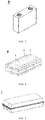
- FIG. 5 and FIG. 6 show a battery pack 1 as an example.
- the battery pack 1 may include a battery box and a plurality of battery modules 4 disposed in the battery box.
- the battery box includes an upper box body 2 and a lower box body 3, where the upper box body 2 can cover the lower box body 3 to form an enclosed space for accommodating the battery modules 4.
- the plurality of battery modules 4 may be arranged in the battery box in any manner.
- the device may be, but is not limited to, a mobile device (for example, a mobile phone or a notebook computer), an electric vehicle (for example, a battery electric vehicle, a hybrid electric vehicle, a plug-in hybrid electric vehicle, an electric bicycle, an electric scooter, an electric golf vehicle, or an electric truck), an electric train, a ship, a satellite, an energy storage system, and the like.
- a mobile device for example, a mobile phone or a notebook computer
- an electric vehicle for example, a battery electric vehicle, a hybrid electric vehicle, a plug-in hybrid electric vehicle, an electric bicycle, an electric scooter, an electric golf vehicle, or an electric truck
- an electric train for example, a ship, a satellite, an energy storage system, and the like.
- a secondary battery (cell), a battery module (module), or a battery pack (pack) may be selected for the device according to requirements for using the device.
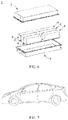
- FIG. 7 is a device as an example.
- the device is a battery electric vehicle, a hybrid electric vehicle, a plug-in hybrid electric vehicle, or the like.
- a battery pack or a battery module may be used.
- the device may be a mobile phone, a tablet computer, a notebook computer, or the like.
- Such device is generally required to be light and thin, and may use a secondary battery as its power source.
- a binding substance, a conductive substance, and a special sensitive substance were dissolved in a solvent at a ratio.
- the resulting mixture was thoroughly stirred and then evenly applied onto at least one surface of a positive electrode current collector, followed by drying to obtain a safety layer applied onto the positive electrode current collector.
- Positive electrode plate of this application A positive electrode active material and a solvent were mixed at a ratio. The resulting mixture was thoroughly stirred to obtain a uniform positive electrode slurry, and then the positive electrode slurry was evenly applied onto a the positive electrode current collector that has been coated with the safety layer in step 1), followed by drying and cold pressing to obtain a positive electrode plate.
- Positive electrode plate not of this application A positive electrode active material, a conductive substance, and a binding substance were mixed at a ratio and dissolved in a solvent. The resulting mixture was thoroughly stirred and evenly applied onto at least one surface of a positive electrode current collector, followed by drying and cold pressing to obtain a positive electrode plate.
- the solvents used in step 1) and step 2) could be N-methylpyrrolidone (NMP) and/or N,N-dimethylformamide (DMF), or other types of solvents previously described.
- NMP N-methylpyrrolidone
- DMF N,N-dimethylformamide
- Ethylene carbonate (EC), propylene carbonate (PC), and dimethyl carbonate (DMC) were mixed uniformly at a mass ratio of 1:1:1 to obtain a mixed organic solvent; then a lithium salt LiPF 6 was dissolved in the mixed organic solvent. The mixture was mixed uniformly to obtain an electrolyte. A concentration of LiPF 6 was 1 mol/L.
- the positive electrode plate, a separator porous polyethylene, and the negative electrode plate were stacked in order and the resulting stack was wound to obtain a battery cell; and the battery cell was placed in an outer package, the electrolyte was injected, and then the outer package was sealed to obtain a lithium-ion secondary battery.
- Lithium-ion secondary batteries of this application were prepared in the foregoing method according to specific components and proportions shown in Table 1.
- Lithium-ion secondary batteries not of this application were prepared in the foregoing method according to specific components and proportions shown in Table 1.
- the lithium-ion secondary battery was charged to 4.25V at a constant current rate of 1C, then charged to a current of 0.05C at a constant voltage of 4.25V, and then left standing for 30 minutes. Then, the battery was fixed with a clamper and placed on an overcharge safety test device with ambient temperature controlled within 25 ⁇ 2°C. After standing for 5 minutes, the fully charged battery was overcharged at a rate of 1C, and the real-time voltage and temperature changes of each battery were recorded until the battery caught a fire or exploded, or the charging stopped. Six samples of lithium-ion secondary batteries were tested for each of the examples and comparative examples. The test passed if no battery caught a fire or exploded, and otherwise failed.
- the lithium-ion secondary battery was charged to 4.25 V at a constant current of 1C, charged to a current of 0.05C at a constant voltage of 4.25V, left standing for 5 min, and then discharged to 2.8V at a constant current of 1C, which was one charge and discharge cycle. Discharge capacity of this cycle was discharge capacity of the 1st cycle.
- Example 1 Pass rate of overcharge safety performance test Capacity retention rate (%) after 200 cycles at 45°C
- Example 1 6/6 91.2
- Example 2 6/6 92.8
- Example 3 6/6 93.7
- Example 4 5/6 94.5
- Example 5 3/6 94.1
- Example 6 6/6 94.2
- Example 7 3/6 94
- Example 8 2/6 93.9
- Example 9 6/6 94.3
- Example 10 6/6 94.4
- Example 11 3/6 94.1
- Example 12 2/6 93.8
- Example 13 6/6 94.1
- Example 14 5/6 94.5
- Example 15 3/6 94.2
- Example 16 6/6 95.10
- Example 17 6/6 91.20
- Example 18 4/6 89.30
- Example 19 3/6 83.30
- Example 20 6/6 93.90
- Example 21 4/6 94.30
- Example 22 5/6 94.20
- Example 23 6/6 93.90
- Example 24 6/6 91.40
- Example 27 6/6 92.40
- Example 28 6/6 93.10
- Example 34 used a special sensitive substance with only a low degree of esterification (only 35%), and the safety performance of the lithium-ion battery was slightly improved and the electrical performance (such as cycling performance) was slightly deteriorated, but overall performance of the battery was still better than that of Comparative Examples 1 to 4.
- Examples 16 to 19 used positive electrode plates with different single-sided capacity per unit area, and it can be seen that as the single-sided capacity per unit area increased, the improvement of safety performance of the battery brought by the safety layer tended to drop and the electrical performance (such as cycling performance) declined, but the overall performance of the battery was still better than that of Comparative Examples 1 to 4.
- Table 1 and Table 2 it can be seen from Table 1 and Table 2 that the lithium-ion secondary battery manifested significantly improved safety and electrical performance (such as cycling performance) whether the safety layer containing the special sensitive substance in this application was applied onto one or two sides of the positive electrode current collector.
- FIG. 1 is a voltage-temperature-time curve of the lithium-ion secondary battery of Example 16 according to this application. It can be seen that when the battery was overcharged, the special sensitive substance in the safety layer could respond quickly to cut off external charging current and restrain the battery temperature from rising, thereby improving the overcharge safety performance of the battery.
- FIG. 2 is a voltage-temperature-time curve of the lithium-ion secondary battery of Comparative Example 4. It can be seen that when the battery was overcharged, the temperature of the battery rose sharply, and the battery failed due to thermal runaway, making the battery prone to safety risks such as fire and explosion. It can be seen from comparing FIG. 1 and FIG. 2 that the lithium-ion secondary battery prepared by adding a special sensitive substance in the safety layer had significantly improved overcharge safety performance.
Landscapes
- Chemical & Material Sciences (AREA)
- Engineering & Computer Science (AREA)
- Chemical Kinetics & Catalysis (AREA)
- Electrochemistry (AREA)
- General Chemical & Material Sciences (AREA)
- Manufacturing & Machinery (AREA)
- Materials Engineering (AREA)
- Secondary Cells (AREA)
- Battery Electrode And Active Subsutance (AREA)
Abstract
Description
- This application claims priority to
Chinese Patent Application No. 201910731214.9, filed with the China National Intellectual Property Administration on August 08, 2019 - This application relates to the electrochemical filed, and in particular to a positive electrode plate and an electrochemical apparatus and device associated therewith.
- Lithium-ion batteries are widely applied to electric vehicles and consumer electronic products due to their advantages such as high energy density, high output power, long cycle life, and low environmental pollution. However, lithium-ion batteries sometimes have safety issues such as fire and explosion during overcharge, which poses a great threat to the safety of people's lives and property. In addition, the recycling rate of lithium-ion batteries has also been questioned. Overcharge of a lithium-ion battery generally deteriorates its electrical performance, resulting in lithium precipitation on its negative electrode, which significantly deteriorates electrical performance such as cycling and capacity, and even causes short circuit in the battery. Results of a large number of experiments show that short circuit in the battery is the root cause of safety hazards of lithium-ion batteries. Researchers have tried to make improvements in many aspects in an attempt to avoid in-battery short circuit, including research on exploiting properties of PTC (Positive Temperature Coefficient) materials to improve safety performance of lithium-ion batteries. PTC materials, also referred to as positive temperature coefficient thermal materials, are characterized in having electric resistivity that increases with temperature. When the temperature exceeds a particular threshold, electric resistivity of a PTC material steps up rapidly.
- A known typical practice to improve safety of a lithium-ion battery is adding a PTC material to an active material layer of the battery. As the battery temperature rises, resistance of the PTC material grows, increasing resistance of the entire active material layer, and even damaging the charge conducting path of the entire active material layer, thus cutting off the power and prohibiting further electrochemical reaction. However, experiments have shown that the PTC material added to the active material layer has an adverse effect on electrochemical performance of the battery.
- It has also been reported that a separate PTC material layer could be disposed between a current collector and an active material layer of a lithium-ion battery. As the battery temperature rises, resistance of the PTC material layer grows, increasing resistance between the current collector and the active material layer, and even cutting off the power, thus prohibiting further electrochemical reaction. However, according to such method of improvement, when an active material slurry is applied onto a surface of the PTC material layer, a solvent in the slurry (such as NMP) will dissolve the PTC material in the PTC layer and enter an upper active material layer, which not only makes the PTC layer lose PTC effect but also deteriorates electrical performance of the lithium-ion battery. In addition, in a compaction step for preparing an electrode plate, the PTC material layer is extremely easy to be taken to the edge because of squeezing, resulting in direct contact between the active material layer and the current collector, thereby failing to improve the safety performance. In addition, performances such as response speed and current blocking effect of the PTC material layer all need to be greatly improved.
- Some embodiments of this application provide a positive electrode plate with improved safety and electrical performance (such as cycling performance) and an electrochemical apparatus and device associated therewith.
- According to one aspect, this application provides a positive electrode plate, including a positive electrode current collector, a positive electrode active material layer disposed on at least one surface of the positive electrode current collector, and a safety layer disposed between the positive electrode active material layer and the positive electrode current collector. The safety layer includes a binding substance, a conductive substance, and a special sensitive substance. Each molecule of the special sensitive substance includes monosaccharide structural units, and carbonate groups and/or phosphate groups; and at least part of the carbonate groups and/or phosphate groups are bonded to two or more of the monosaccharide structural units. According to another aspect, this application provides an electrochemical apparatus, including the positive electrode plate according to the first aspect of this application.
- According to this application, when overcharge occurs, excessive voltage and certain temperature will cause the special sensitive substance in the safety layer of the positive electrode plate to be degraded, thus damaging a charge conducting network in the safety layer, blocking electronic conduction between the positive electrode current collector and the positive electrode activity material layer, thereby cutting off a charging current in time, effectively preventing the electrochemical apparatus from thermal runaway, and avoiding safety problems such as fire and explosion, which greatly improves overcharge safety performance of the electrochemical apparatus.
- Compared with a positive electrode plate and an electrochemical apparatus that use a traditional PTC material as a safety layer or use an active material layer containing a PTC material, the positive electrode plate and the electrochemical apparatus including such positive electrode plate in this application undergo chemical changes first instead of physical changes at excessive high voltage and certain temperature, providing faster response, controllable response voltage, better overcharge safety and reliability, and improved electrical performance (such as cycling performance) of the electrochemical apparatus. The traditional PTC material whose volume swelling relies on changes in crystallinity only undergoes physical changes at high temperature. Such change is greatly affected by preparation processes of a material coating and the electrochemical apparatus. For example, temperature and coating speed in the preparation process of the material coating and an electrolyte in the electrochemical apparatus all have an uncontrollable effect on crystallinity of the material. When the electrochemical apparatus is overcharged, the material may probably not be excited, and therefore the charging current cannot be cut off in time, posing a safety hazard.
- According to another aspect, this application provides a battery module including the foregoing electrochemical apparatus.
- According to still another aspect, this application provides a battery pack including the foregoing battery module.
- According to a still further aspect, this application provides a device including the foregoing electrochemical apparatus. The electrochemical apparatus can be used as a power source of the device or as an energy storage unit of the device.
- The battery module, battery pack, and device in this application include the electrochemical apparatus provided by this application, and therefore have at least the same advantages as the electrochemical device in this application.
- To describe the technical solutions in the embodiments of this application more clearly, the following briefly describes the accompanying drawings required for describing the embodiments of this application. Apparently, the accompanying drawings in the following description show merely some embodiments of this application, and a person of ordinary skill in the art may still derive other drawings from these accompanying drawings without creative efforts.
-
FIG. 1 is a voltage-temperature-time curve of a lithium-ion secondary battery of Example 16 of this application; -
FIG. 2 is a voltage-temperature-time curve of a lithium-ion secondary battery of Comparative Example 4; -
FIG. 3 is a schematic diagram of an embodiment of a secondary battery; -
FIG. 4 is a schematic diagram of an embodiment of a battery module; -
FIG. 5 is a schematic diagram of an embodiment of a battery pack; -
FIG. 6 is an exploded view ofFIG. 5 ; and -
FIG. 7 is a schematic diagram of an embodiment of a device using a secondary battery as a power source. - Reference signs are as follows:
- 1.
- battery pack;
- 2.
- upper box body;
- 3.
- lower box body;
- 4.
- battery module; and
- 5.
- secondary battery.
- The following will describe this application in detail with reference to specific examples. It should be understood that the embodiments described in this specification are merely intended to interpret this application, but not intended to limit this application. The formulations and proportions in the embodiments can be selected as appropriate, but are still within the protection scope of this application.
- For simplicity, only some numerical ranges are exemplarily disclosed in this specification. However, any lower limit may be combined with any upper limit to form a range not expressly recorded; any lower limit may be combined with any other lower limit to form a range not expressly recorded; and any upper limit may be combined with any other upper limit to form a range not expressly recorded. In addition, although not expressly recorded, each point or individual value between endpoints of a range is included in the range. Therefore, each point or individual value may be used as its own lower limit or upper limit to be combined with any other point or individual value or combined with any other lower limit or upper limit to form a range not expressly recorded. It should be understood that the enumeration of numerical values is merely giving examples and should not be interpreted as exhaustive.
- In the descriptions of this specification, it should be noted that, unless otherwise stated, "more than", "less than", "≤", and "≥" are all inclusive of the present number, "at least one" means including one or more, and "more" in "one or more" means two or more than two.
- In an embodiment of this application, a positive electrode plate is provided, including a positive electrode current collector, a positive electrode active material layer disposed on at least one surface of the positive electrode current collector, and a safety layer disposed between the positive electrode current collector and the positive electrode active material layer. In a specific embodiment, the safety layer includes a special sensitive substance. In an embodiment of this application, the special sensitive substance includes at least one product of esterification of polysaccharide.
- The applicant has found that disposing the product of esterification of polysaccharide in the safety layer leads to an electrochemical degradation reaction at certain voltage or temperature to produce molecular fragments with monosaccharide structural units and ester groups. These molecular fragments have good affinity with an electrolyte. To be specific, the degraded polysaccharide esterified product is dissolved or dispersed in the electrolyte, able to block the charging process.
- According to this application, a weight-average molecular weight of the special sensitive substance cannot be excessively high or excessively low. Excessive high molecular weight affects the affinity of the special sensitive substance with the electrolyte and the solubility in preparing the safety layer, causing failure to respond quickly. Excessively low weight-average molecular weight would not only fail to maintain a charge conducting network in the safety layer but also lead to excessively low decomposition voltage or temperature so that the battery cannot function properly. In an embodiment of this application, the weight-average molecular weight Mw of the special sensitive substance is from 1000 to 28000. For example, the weight-average molecular weight Mw of the special sensitive substance may be 1000, 1200, 1500, 2000, 2500, 3000, 3500, 4000, 4500, 5000, 5500, 6000, 6500, 7000, 7500, 8000, 8200, 8500, 9000, 9500, 10000, 11000, 12000, 13000, 14000, 15000, 16000, 17000, 18000, 19000, 20000, 25000, or 28000, including any and all ranges and sub-ranges thereof, for example, 1000 to 10000, 1000 to 20000, 1000 to 25000, 1200 to 10000, 1200 to 28000, 1200 to 19000, 1200 to 10000, 3000 to 10000, 3000 to 20000, 3000 to 28000, 5000 to 10000, 5000 to 11000, 5000 to 20000, or 5000 to 28000.
- In a specific embodiment of this application, the special sensitive substance includes at least one product of esterification of polysaccharide containing 2 to 80 monosaccharide units, for example, 2, 5, 10, 15, 20, 25, 30, 35, 40, 45, 50, 55, 60, 65, 70, 75, or 80, including any and all ranges and sub-ranges thereof, for example, 2 to 50, 2 to 40, 2 to 30, 5 to 10, 5 to 30, 10 to 30, 20 to 30, 30 to 40, 40 to 50, 50 to 60, 60 to 70, or 60 to 80. The quantity of monosaccharide units in the special sensitive substance is related to overcharge safety performance and electrical performance of the electrochemical apparatus using the positive electrode plate.
- In addition, the applicant has also discovered that the degree of esterification of the monosaccharide units in the special sensitive substance further affects the amount of its residual hydroxyl groups. These residual hydroxyl groups can activate and promote degradation of the special sensitive substance under certain voltage or temperature. However, excessive residual hydroxyl groups may deteriorate the electrical performance of the electrochemical apparatus.
- In an embodiment of this application, the degree of esterification of the monosaccharide units in the special sensitive substance is 35% to 98%, which is more conducive to affinity between the special sensitive substance and the electrolyte. For example, the degree of esterification of monosaccharide units in the special sensitive substance may be 35%, 40%, 45%, 50%, 55%, 60%, 65%, 70%, 75%, 80%, 85%, 88%, 90%, 92%, or 98%, including any and all ranges and sub-ranges thereof, for example, 35% to 92%, 35% to 90%, 35% to 88%, 50% to 98%, 50% to 92%, 50% to 90%, 50% to 88%, 60% to 98%, 60% to 92%, 60% to 90%, or 60% to 88%.
- In an embodiment of this application, the product of esterification of polysaccharide is selected from at least one of the following: dextrin carbonate and its derivatives, dextrin phosphate and its derivatives, dextrin sulfate and its derivatives, chitosan carbonate and its derivatives, chitosan phosphate and its derivatives, chitosan sulfate and its derivatives, degraded cellulose carbonate and its derivatives, degraded cellulose phosphate and its derivatives, degraded cellulose sulfate and its derivatives, hyaluronic acid carbonate and its derivatives, hyaluronic acid phosphate and its derivatives, hyaluronic acid sulfate and its derivatives, chondroitin sulfate carbonate and its derivatives, chondroitin sulfate sulfate and its derivatives, chondroitin sulfate phosphate and its derivatives, sucrose carbonate and its derivatives, sucrose phosphate and its derivatives, sucrose sulfate and its derivatives, heparin carbonate and its derivatives, heparin sulfate and its derivatives, or heparin phosphate and its derivatives.
- In an embodiment of this application, the product of esterification of polysaccharide is selected from at least one of the following: dextrin carbonate and its derivatives, dextrin phosphate and its derivatives, chitosan carbonate and its derivatives, chitosan phosphate and its derivatives, degraded cellulose carbonate and its derivatives, degraded cellulose sulfate and its derivatives, degraded cellulose phosphate and its derivatives, hyaluronic acid sulfate and its derivatives, or sucrose phosphate and its derivatives.
- The carbonate, sulfate, and phosphate groups in polysaccharide carbonated products, polysaccharide sulfated products, or polysaccharide phosphorylated products have good compatibility with carbonate groups in common electrolytes, favorable for infiltration of the electrolyte. In addition, the carbonate, sulfate, and phosphate groups contained in small molecules resulting from breakage due to overcharge have good affinity with the electrolyte, and are miscible in the electrolyte to become a colloidal state, thereby increasing response speed of the safety layer. In a specific embodiment of this application, the product of esterification of polysaccharide is selected from at least one of the following: dextrin methyl carbonate, dextrin ethyl carbonate, dextrin methyl phosphate, dextrin ethyl phosphate, chitosan methyl carbonate, chitosan ethyl carbonate, chitosan methyl phosphate, chitosan ethyl phosphate, degraded cellulose methyl carbonate, degraded cellulose ethyl carbonate, degraded cellulose methyl sulfate, degraded cellulose ethyl sulfate, degraded cellulose methyl phosphate, degraded cellulose ethyl phosphate, hyaluronic acid methyl sulfate, hyaluronic acid ethyl sulfate, sucrose methyl phosphate, or sucrose ethyl phosphate.
- In order for the safety layer to better perform its role, in an embodiment of this application, the special sensitive substance accounts for 25% to 60% of total mass of the safety layer, for example, 25%, 30%, 35%, 37%, 40%, 45%, 50%, 54%, 55%, or 60%, including any and all ranges and sub-ranges thereof, for example, 20% to 55%, 20% to 50%, 20% to 40%, 30% to 60%, 30% to 55%, 30% to 50%, or 30% to 40%.
- According to this application, the safety layer further includes a binding substance, and the embodiments of this application impose no limitations on a type of the binding substance. As an example, in an embodiment of this application, the binding substance includes one or more of polyvinylidene fluoride (PVDF), vinylidene fluoride-hexafluoropropylene copolymers, polyurethane, polyacrylonitrile, polyimide, epoxy resin, silicone resin, ethylene-vinyl acetate copolymers, sodium carboxymethyl cellulose (CMC), styrene-butadiene rubber (SBR), styrene-acrylic rubber, polyacrylic acid, polyacrylic acid-acrylate copolymers, and polyethylene-acrylate copolymers. In a specific embodiment, the binding substance includes one or more of polyvinylidene fluoride, vinylidene fluoride-hexafluoropropylene copolymers, styrene-butadiene rubber, and sodium carboxymethyl cellulose. When the safety layer includes two or more binding substances, a ratio of the binding substances is not particularly limited provided that the technical solution of this application can be implemented. For example, in a case of two such binding substances, a mass ratio therebetween may be 1:1, 2:8 or 8:2, 3:7 or 7:3, or 4:6 or 6:4.
- In one embodiment, the binding substance accounts for 25% to 60% of total mass of the safety layer, for example, 25%, 28%, 30%, 32%, 35%, 40%, 45%, 50%, 53%, 54%, 55%, 57%, 58%, 59%, or 60%, including any and all ranges and sub-ranges thereof,
- for example, 25% to 59%, 25% to 58%, 25% to 57%, 25% to 55%, 25% to 53%, 25% to 50%, 28% to 60%, 28% to 55%, 28% to 50, 30% to 60%, 30% to 55%, or 30% to 50%.
- According to this application, the safety layer further includes a conductive substance, and the embodiments of this application impose no limitations on a type of the conductive substance. As an example, in an embodiment of this application, the conductive substance includes one or more of a metal conductive material, a carbon-based conductive material, and a conductive polymer material. In a specific embodiment, the metal conductive material is selected from at least one of aluminum, aluminum alloy, copper, copper alloy, nickel, nickel alloy, titanium, or silver. In a specific embodiment, the carbon-based conductive material is selected from at least one of Ketjen black, carbonaceous mesophase spherule, activated carbon, graphite, conductive carbon black (Super-P), acetylene black, carbon fiber, carbon nanotube (CNT), or graphene. In a specific embodiment, the conductive polymer material includes at least one of polysulfur nitrides, aliphatic conjugated polymers, aromatic conjugated polymers, or aromatic heterocyclic conjugated polymers. When the safety layer includes two or more conductive substances, a ratio of the conductive substances is not particularly limited provided that the technical solution of this application can be implemented. For example, in a case of two such conductive substances, a mass ratio therebetween may be 1:1, 2:8 or 8:2, 3:7 or 7:3, or 4:6 or 6:4.
- In one embodiment, the conductive substance accounts for 4% to 20% of total mass of the safety layer, for example, 4%, 5%, 6%, 8%, 10%, 15%, 18%, or 20%, including any and all ranges and sub-ranges thereof, for example, 4% to 10%, 4% to 18%, 5% to 20%, 5% to 18%, 5% to 10%, 6% to 20%, 6% to 18%, or 6% to 10%.
- According to this application, the positive electrode current collector is a conventional positive electrode current collector (such as aluminum foil) known in the art that can be used in a capacitor, a primary battery, or a secondary battery, and composition and preparation methods thereof are known in the art and are not limited or further described herein provided that the technical solution of this application can be implemented.
- According to this application, at least one surface of the positive electrode current collector is coated with a positive electrode active material layer. In a specific embodiment, one or two surfaces of the positive electrode current collector are coated with the positive electrode active material layer. It should be noted that the safety layer is disposed between the positive electrode current collector and the positive electrode active material layer, and therefore the safety layer has the same quantity as the positive electrode active material layer. To be specific, if one surface of the positive electrode current collector is coated with the positive electrode active material layer, the positive electrode current collector has one safety layer; and if two surfaces of the positive electrode current collector are both coated with the positive electrode active material layer, the positive electrode current collector has two safety layers. According to this application, the safety layer has no special requirements for thickness, and for example, its thickness may be 1 µm, 1.5 µm, 2 µm, 2.5 µm, or 3 µm, including any and all ranges and sub-ranges thereof, for example, 1 µm to 3 µm, 2 µm to 3 µm, or ≤3 µm. The thickness is not limited or further described herein provided that the technical solution of this application can be implemented.
- The positive electrode active material layer used in this application can be selected from various positive electrode active material layers known in the art that are suitable for capacitors, primary batteries, or secondary batteries, and composition and preparation methods thereof are known in the art. The positive electrode active material layer includes a positive electrode active material, which may be a conventional positive electrode active material known in the art that can be used in a capacitor, a primary battery, or a secondary battery, for example, lithium-containing composite metal oxides, and specifically, for example, LiCoO2(LCO), LiNiO2(LNO), LiMn2O4(LMO), LiFePO4(LFP), one or more of lithium nickel cobalt manganese oxides (NCM) (such as NCM811, MCM523, and MCM622, 811, 523, and 622 for short), or one or more of lithium nickel manganese oxides (NCA), which is not limited or further described herein provided that the technical solution of this application can be implemented.
- The positive electrode plate of this application can be prepared according to conventional methods in the art. As an example, the binding substance, conductive substance, and special sensitive substance are dissolved in a solvent at a ratio. The resulting mixture is thoroughly stirred and then applied evenly onto at least one surface of the positive electrode current collector, followed by drying to obtain a safety layer applied on the positive electrode current collector. Then, the positive electrode active material is dissolved in the solvent to form a uniform positive electrode slurry, and the positive electrode slurry is evenly applied onto the surface of the positive electrode current collector that has been coated with the safety layer, and after drying and cold pressing, the positive electrode plate of this application is obtained.
- The solvent used in this application is not particularly limited provided that the technical solution of this application can be implemented. For example, the solvent may be an organic solvent, for example, an ether, a hydrocarbon, an ester, a nitrile, an amide, an alcohol, a halogenated hydrocarbon, or the like. In a specific embodiment, the ether is selected from at least one of diethyl ether, tetrahydrofuran, and ethylene glycol dimethyl ether; the hydrocarbon is selected from at least one of n-pentane, n-hexane, cyclohexane, toluene, or xylene, or trimethylbenzene; the ester is selected from at least one of ethyl acetate, methyl formate, and dimethyl phthalate; the nitriles are selected from acetonitrile; the amide is selected from N-methylpyrrolidone (NMP) and/or N,N-dimethylformamide (DMF); the alcohol is selected from at least one of ethanol or propanol; and the halogenated hydrocarbon is selected from methylene chloride and/or 1,2-dichloroethane.
- A high-capacity positive electrode plate generally undergoes thermal runaway at a faster rate under overcharge. Therefore, a positive electrode plate with appropriate capacity often has greater advantages in terms of fast charging reliability. Tests have shown that when a single-sided capacity per unit area of the positive electrode plate in this application is ≤7 mAh/cm2, for example, ≤7 mAh/cm2, 6.5 mAh/cm2, 6.2 mAh/cm2, 6 mAh/cm2, 5.5 mAh/cm2, 5 mAh/cm2, 4.5 mAh/cm2, 4.1 mAh/cm2, 4 mAh/cm2, 3.5 mAh/cm2, 3.12 mAh/cm2, 3 mAh/cm2, 2.5 mAh/cm2, 2 mAh/cm2, 1.5 mAh/cm2, 1.2 mAh/cm2, 1.0 mAh/cm2, or any value thereof, the positive electrode plate manifests the best performance.
- The special sensitive substance is degraded by chemical reactions, and therefore its degradation conditions are related to both voltage and temperature, rather than single factor control of the PTC material. According to this application, the overcharge sensitive substance of the positive electrode plate is degraded at a charging voltage of α V and temperature of β°C, where 4.2≤α≤5.5, 4.2≤α≤4.5, 4.5≤α≤4.8, 4.8 ≤α≤5.2, 5.2≤α≤5.5, 5.5≤α≤6.0, or 6.0≤α≤6.5, and 35≤β≤80, 35≤β≤40, 40≤β≤45, 45≤β≤50, 50≤ β≤55, 55≤β≤60, 60≤β≤65, 65≤β≤70, 70≤β≤75, 75≤β≤80, 80≤β≤85, 85≤β≤90, or 90≤β≤ 95. A positive electrode plate with the above α and β ranges can ensure both normal use at normal voltage and temperature and reliability of safety performance under overcharge.
- In another aspect, this application further provides an electrochemical apparatus, including the positive electrode plate described above. In a specific embodiment, the electrochemical apparatus may be a capacitor, a bare cell, or a primary or secondary battery containing a bare cell, for example, a lithium primary battery, a lithium-ion secondary battery, a sodium-ion battery, or a magnesium-ion battery, but is not limited thereto.
- In addition to including the positive electrode plate in this application, the electrochemical apparatus is known in the art in terms of construction and preparation method. The electrochemical apparatus has improved safety and electrical performance (such as cycling performance) because of use of the positive electrode plate in this application. In addition, the positive electrode plate in this application can be easily processed, and therefore manufacturing costs of the electrochemical apparatus using the positive electrode plate in this application can be reduced.
- When the electrochemical apparatus in this application is overcharged, the special sensitive substance in the safety layer undergoes a chemical reaction, which in turn causes conductive substance particles in the safety layer to separate and the charge conducting network to break, making internal resistance of the electrochemical apparatus increase sharply, thereby cutting off the charging current in time, effectively preventing the electrochemical apparatus from thermal runaway, and avoiding safety problems such as fire and explosion, which greatly improves the overcharge safety performance of the electrochemical apparatus.
- Compared with the design of using a traditional PTC material as a safety layer, the safety layer including the special sensitive substance in this application has better reliability, allowing an electrochemical apparatus prepared by using a positive electrode plate including such safety layer, for example, a lithium-ion secondary battery, to have better safety. The traditional PTC material whose volume swelling relies on changes in crystallinity only undergoes physical changes at high temperature. Such change is greatly affected by preparation processes of a material coating and the electrochemical apparatus. For example, temperature and coating speed in the preparation process of the material coating and an electrolyte in the electrochemical apparatus all have an uncontrollable effect on crystallinity of the material. When the electrochemical apparatus is overcharged, the material may probably not be excited, and therefore the charging current cannot be cut off in time, posing a safety hazard.
- In a specific embodiment of this application, the electrochemical apparatus is a secondary battery. This application does not impose special limitations on a shape of the secondary battery, and the lithium-ion battery may be of a cylindrical shape, a square shape, or any other shapes.
FIG. 3 is asecondary battery 5 of a square structure as an example. - In some embodiments, such secondary batteries may be combined to assemble a battery module. The battery module may include a plurality of secondary batteries whose quantity may be adjusted according to the use case and capacity of the battery module.
-
FIG. 4 shows abattery module 4 used as an example. Referring toFIG. 4 , in thebattery module 4, a plurality ofsecondary batteries 5 may be sequentially arranged along a length direction of thebattery module 4. Certainly, the plurality oflithium metal batteries 5 may be arranged in any other manners. Further, the plurality ofsecondary batteries 5 may be fastened by using fasteners. - Optionally, the
battery module 4 may further include a housing with an accommodating space, and the plurality ofsecondary batteries 5 are accommodated in the accommodating space. - In some embodiments, such battery modules may be further combined to assemble a battery pack, and a quantity of battery modules included in the battery pack may be adjusted based on the use case and capacity of the battery pack.
-
FIG. 5 andFIG. 6 show abattery pack 1 as an example. Referring toFIG. 5 andFIG. 6 , thebattery pack 1 may include a battery box and a plurality ofbattery modules 4 disposed in the battery box. The battery box includes anupper box body 2 and alower box body 3, where theupper box body 2 can cover thelower box body 3 to form an enclosed space for accommodating thebattery modules 4. The plurality ofbattery modules 4 may be arranged in the battery box in any manner. - Another aspect of this application provides a device that includes the foregoing secondary battery, and the secondary battery can be used as a power source of the device or as an energy storage unit of the device. The device may be, but is not limited to, a mobile device (for example, a mobile phone or a notebook computer), an electric vehicle (for example, a battery electric vehicle, a hybrid electric vehicle, a plug-in hybrid electric vehicle, an electric bicycle, an electric scooter, an electric golf vehicle, or an electric truck), an electric train, a ship, a satellite, an energy storage system, and the like.
- A secondary battery (cell), a battery module (module), or a battery pack (pack) may be selected for the device according to requirements for using the device.
-
FIG. 7 is a device as an example. The device is a battery electric vehicle, a hybrid electric vehicle, a plug-in hybrid electric vehicle, or the like. To meet requirements of the device for high power and high energy density of secondary batteries, a battery pack or a battery module may be used. - In another example, the device may be a mobile phone, a tablet computer, a notebook computer, or the like. Such device is generally required to be light and thin, and may use a secondary battery as its power source.
- This application is further described with reference to specific examples. It should be understood that the following exemplary examples are only used for illustration but do not intend to limit this application. Unless otherwise stated, all percentages and ratios reported in the following examples are based on weight, all reagents used in the examples are commercially available or synthesized in a conventional manner, and can be used directly without further treatment. Experimental conditions not specified in the examples adopt conventional conditions, or adopt conditions recommended by material suppliers or equipment suppliers.
- A binding substance, a conductive substance, and a special sensitive substance were dissolved in a solvent at a ratio. The resulting mixture was thoroughly stirred and then evenly applied onto at least one surface of a positive electrode current collector, followed by drying to obtain a safety layer applied onto the positive electrode current collector.
- Positive electrode plate of this application: A positive electrode active material and a solvent were mixed at a ratio. The resulting mixture was thoroughly stirred to obtain a uniform positive electrode slurry, and then the positive electrode slurry was evenly applied onto a the positive electrode current collector that has been coated with the safety layer in step 1), followed by drying and cold pressing to obtain a positive electrode plate.
- Positive electrode plate not of this application: A positive electrode active material, a conductive substance, and a binding substance were mixed at a ratio and dissolved in a solvent. The resulting mixture was thoroughly stirred and evenly applied onto at least one surface of a positive electrode current collector, followed by drying and cold pressing to obtain a positive electrode plate.
- The solvents used in step 1) and step 2) could be N-methylpyrrolidone (NMP) and/or N,N-dimethylformamide (DMF), or other types of solvents previously described.
- Ethylene carbonate (EC), propylene carbonate (PC), and dimethyl carbonate (DMC) were mixed uniformly at a mass ratio of 1:1:1 to obtain a mixed organic solvent; then a lithium salt LiPF6 was dissolved in the mixed organic solvent. The mixture was mixed uniformly to obtain an electrolyte. A concentration of LiPF6 was 1 mol/L.
- The positive electrode plate, a separator porous polyethylene, and the negative electrode plate were stacked in order and the resulting stack was wound to obtain a battery cell; and the battery cell was placed in an outer package, the electrolyte was injected, and then the outer package was sealed to obtain a lithium-ion secondary battery.
- Lithium-ion secondary batteries of this application were prepared in the foregoing method according to specific components and proportions shown in Table 1.
- Lithium-ion secondary batteries not of this application were prepared in the foregoing method according to specific components and proportions shown in Table 1.


- At 25±2°C, the lithium-ion secondary battery was charged to 4.25V at a constant current rate of 1C, then charged to a current of 0.05C at a constant voltage of 4.25V, and then left standing for 30 minutes. Then, the battery was fixed with a clamper and placed on an overcharge safety test device with ambient temperature controlled within 25±2°C. After standing for 5 minutes, the fully charged battery was overcharged at a rate of 1C, and the real-time voltage and temperature changes of each battery were recorded until the battery caught a fire or exploded, or the charging stopped. Six samples of lithium-ion secondary batteries were tested for each of the examples and comparative examples. The test passed if no battery caught a fire or exploded, and otherwise failed.
- At 45±2°C, the lithium-ion secondary battery was charged to 4.25 V at a constant current of 1C, charged to a current of 0.05C at a constant voltage of 4.25V, left standing for 5 min, and then discharged to 2.8V at a constant current of 1C, which was one charge and discharge cycle. Discharge capacity of this cycle was discharge capacity of the 1st cycle. The lithium-ion secondary battery was tested according to the foregoing method for 100 charge and discharge cycles, and the discharge capacity of each cycle was recorded.

- The test results of Examples 1 to 33 and Comparative Examples 1 to 5 are shown in Table 2 below.
Table 2 Pass rate of overcharge safety performance test Capacity retention rate (%) after 200 cycles at 45°C Example 1 6/6 91.2 Example 2 6/6 92.8 Example 3 6/6 93.7 Example 4 5/6 94.5 Example 5 3/6 94.1 Example 6 6/6 94.2 Example 7 3/6 94 Example 8 2/6 93.9 Example 9 6/6 94.3 Example 10 6/6 94.4 Example 11 3/6 94.1 Example 12 2/6 93.8 Example 13 6/6 94.1 Example 14 5/6 94.5 Example 15 3/6 94.2 Example 16 6/6 95.10 Example 17 6/6 91.20 Example 18 4/6 89.30 Example 19 3/6 83.30 Example 20 6/6 93.90 Example 21 4/6 94.30 Example 22 5/6 94.20 Example 23 6/6 93.90 Example 24 6/6 91.40 Example 25 6/6 94.00 Example 26 4/6 94.20 Example 27 6/6 92.40 Example 28 6/6 93.20 Example 29 2/6 94.10 Example 30 4/6 93.7 Example 31 3/6 94 Example 32 5/6 94.2 Example 33 6/6 94.0 Example 34 2/6 88.0 Comparative Example 1 0/6 93.20 Comparative Example 2 0/6 93.80 Comparative Example 3 0/6 93.60 Comparative Example 4 0/6 93.20 - It can be seen from Table 1 and Table 2 that the lithium-ion secondary batteries of this application had obviously better safety and electrical performance (such as cycling performance) than Comparative Examples 1 to 4 that used no special sensitive substances. Example 34 used a special sensitive substance with only a low degree of esterification (only 35%), and the safety performance of the lithium-ion battery was slightly improved and the electrical performance (such as cycling performance) was slightly deteriorated, but overall performance of the battery was still better than that of Comparative Examples 1 to 4. Examples 16 to 19 used positive electrode plates with different single-sided capacity per unit area, and it can be seen that as the single-sided capacity per unit area increased, the improvement of safety performance of the battery brought by the safety layer tended to drop and the electrical performance (such as cycling performance) declined, but the overall performance of the battery was still better than that of Comparative Examples 1 to 4. In summary, it can be seen from Table 1 and Table 2 that the lithium-ion secondary battery manifested significantly improved safety and electrical performance (such as cycling performance) whether the safety layer containing the special sensitive substance in this application was applied onto one or two sides of the positive electrode current collector.
-
FIG. 1 is a voltage-temperature-time curve of the lithium-ion secondary battery of Example 16 according to this application. It can be seen that when the battery was overcharged, the special sensitive substance in the safety layer could respond quickly to cut off external charging current and restrain the battery temperature from rising, thereby improving the overcharge safety performance of the battery.FIG. 2 is a voltage-temperature-time curve of the lithium-ion secondary battery of Comparative Example 4. It can be seen that when the battery was overcharged, the temperature of the battery rose sharply, and the battery failed due to thermal runaway, making the battery prone to safety risks such as fire and explosion. It can be seen from comparingFIG. 1 and FIG. 2 that the lithium-ion secondary battery prepared by adding a special sensitive substance in the safety layer had significantly improved overcharge safety performance. - According to the disclosure and teaching of this specification, those skilled in the art may make further changes or modifications to the foregoing embodiments. Therefore, this application is not limited to the foregoing disclosure and the described embodiments, and some changes or modifications to this application shall also fall within the protection scope of the claims of this application. In addition, although some specific terms are used in this specification, these terms are used only for ease of description, and do not constitute any limitation on this application.
Claims (18)
- A positive electrode plate, comprising:a positive electrode current collector,a positive electrode active material layer disposed on at least one surface of the positive electrode current collector, anda safety layer disposed between the positive electrode current collector and the positive electrode active material layer;whereinthe safety layer comprises a binding substance, a conductive substance, and a special sensitive substance; andthe special sensitive substance comprises at least one product of esterification of polysaccharide.
- The positive electrode plate according to claim 1, wherein a weight-average molecular weight Mw of the special sensitive substance is from 1000 to 28000.
- The positive electrode plate according to claim 1 or 2, wherein the special sensitive substance comprises at least one product of esterification of polysaccharide containing 2 to 80 monosaccharide units.
- The positive electrode plate according to any one of claims 1 to 3, wherein a degree of esterification of monosaccharide units in the product of esterification of polysaccharide is 35% to 98%.
- The positive electrode plate according to any one of claims 1 to 4, wherein the product of esterification of polysaccharide is selected from one or more of the following: dextrin carbonate and its derivatives, dextrin phosphate and its derivatives, dextrin sulfate and its derivatives, chitosan carbonate and its derivatives, chitosan phosphate and its derivatives, chitosan sulfate and its derivatives, degraded cellulose carbonate and its derivatives, degraded cellulose phosphate and its derivatives, degraded cellulose sulfate and its derivatives, hyaluronic acid carbonate and its derivatives, hyaluronic acid phosphate and its derivatives, hyaluronic acid sulfate and its derivatives, chondroitin sulfate carbonate and its derivatives, chondroitin sulfate sulfate and its derivatives, chondroitin sulfate phosphate and its derivatives, sucrose carbonate and its derivatives, sucrose phosphate and its derivatives, sucrose sulfate and its derivatives, heparin carbonate and its derivatives, heparin sulfate and its derivatives, and heparin phosphate and its derivatives.
- The positive electrode plate according to any one of claims 1 to 5, wherein the product of esterification of polysaccharide is selected from one or more of the following: dextrin methyl carbonate, dextrin ethyl carbonate, dextrin methyl phosphate, dextrin ethyl phosphate, chitosan methyl carbonate, chitosan ethyl carbonate, chitosan methyl phosphate, chitosan ethyl phosphate, degraded cellulose methyl carbonate, degraded cellulose ethyl carbonate, degraded cellulose methyl sulfate, degraded cellulose ethyl sulfate, degraded cellulose methyl phosphate, degraded cellulose ethyl phosphate, hyaluronic acid methyl sulfate, hyaluronic acid ethyl sulfate, sucrose methyl phosphate, and sucrose ethyl phosphate.
- The positive electrode plate according to any one of claims 1 to 6, wherein the special sensitive substance accounts for 25% to 60% of total mass of the safety layer.
- The positive electrode plate according to any one of claims 1 to 7, wherein the binding substance comprises one or more of polyvinylidene fluoride, vinylidene fluoride-hexafluoropropylene copolymers, polyurethane, polyacrylonitrile, polyimide, epoxy resin, silicone resin, ethylene-vinyl acetate copolymers, styrene-butadiene rubber, styrene-acrylic rubber, polyacrylic acid, polyacrylic acid-acrylate copolymers, and polyethylene-acrylate copolymers.
- The positive electrode plate according to any one of claims 1 to 8, wherein the binding substance accounts for 25% to 60% of total mass of the safety layer.
- The positive electrode plate according to any one of claims 1 to 9, wherein the conductive substance comprises one or more of a metal conductive material, a carbon-based conductive material, and a conductive polymer material.
- The positive electrode plate according to any one of claims 1 to 10, wherein the metal conductive material comprises one or more of aluminum, aluminum alloy, copper, copper alloy, nickel, nickel alloy, titanium, and silver; the carbon-based conductive material comprises one or more of Ketjen black, carbonaceous mesophase spherule, activated carbon, graphite, conductive carbon black, acetylene black, carbon fiber, carbon nanotube, and graphene; and the conductive polymer material comprises one or more of polysulfur nitrides, aliphatic conjugated polymers, aromatic conjugated polymers, and aromatic heterocyclic conjugated polymers.
- The positive electrode plate according to any one of claims 1 to 11, wherein the conductive substance accounts for 4% to 20% of total mass of the safety layer.
- The positive electrode plate according to any one of claims 1 to 12, wherein a single-sided capacity per unit area of the positive electrode plate is ≤ 7 mAh/cm2.
- An electrochemical apparatus, comprising the positive electrode plate according to any one of the claims 1 to 13.
- The electrochemical apparatus according to claim 14, wherein the electrochemical apparatus may be a capacitor, a primary battery, or a secondary battery.
- A battery module, comprising the electrochemical apparatus according to claim 14 or 15.
- A battery pack, comprising the battery module according to claim 16.
- A device, comprising the electrochemical apparatus according to claim 14 or 15, wherein the device is selected from one or more of an electric vehicle, an electric ship, an electric tool, an electronic device, and an energy storage system.
Applications Claiming Priority (2)
| Application Number | Priority Date | Filing Date | Title |
|---|---|---|---|
| CN201910731214.9A CN110429240B (en) | 2019-08-08 | 2019-08-08 | Positive pole piece and electrochemical device including the positive pole piece |
| PCT/CN2020/106467 WO2021023133A1 (en) | 2019-08-08 | 2020-07-31 | Positive electrode plate and electrochemical device and equipment associated therewith |
Publications (3)
| Publication Number | Publication Date |
|---|---|
| EP3979397A1 true EP3979397A1 (en) | 2022-04-06 |
| EP3979397A4 EP3979397A4 (en) | 2022-07-27 |
| EP3979397B1 EP3979397B1 (en) | 2023-09-06 |
Family
ID=68413307
Family Applications (1)
| Application Number | Title | Priority Date | Filing Date |
|---|---|---|---|
| EP20849080.5A Active EP3979397B1 (en) | 2019-08-08 | 2020-07-31 | Positive electrode plate and electrochemical device and equipment associated therewith |
Country Status (4)
| Country | Link |
|---|---|
| US (1) | US11894524B2 (en) |
| EP (1) | EP3979397B1 (en) |
| CN (1) | CN110429240B (en) |
| WO (1) | WO2021023133A1 (en) |
Families Citing this family (4)
| Publication number | Priority date | Publication date | Assignee | Title |
|---|---|---|---|---|
| CN110429240B (en) * | 2019-08-08 | 2020-12-04 | 宁德时代新能源科技股份有限公司 | Positive pole piece and electrochemical device including the positive pole piece |
| CN110400933B (en) * | 2019-08-08 | 2020-12-04 | 宁德时代新能源科技股份有限公司 | Positive pole piece and electrochemical device including the positive pole piece |
| CN110444764B (en) * | 2019-08-08 | 2020-12-22 | 宁德时代新能源科技股份有限公司 | Positive pole piece and electrochemical energy storage device |
| CN114256518B (en) | 2020-09-25 | 2024-04-26 | 珠海冠宇电池股份有限公司 | A positive electrode sheet and a lithium ion battery comprising the positive electrode sheet |
Family Cites Families (32)
| Publication number | Priority date | Publication date | Assignee | Title |
|---|---|---|---|---|
| JPH08329978A (en) | 1995-05-30 | 1996-12-13 | Shin Kobe Electric Mach Co Ltd | Method of manufacturing alkaline storage battery |
| JP2000100437A (en) | 1998-09-24 | 2000-04-07 | Daicel Chem Ind Ltd | Binder, laminate and lithium secondary battery using the same |
| JP5249258B2 (en) * | 2005-02-10 | 2013-07-31 | 昭和電工株式会社 | Secondary battery current collector, secondary battery positive electrode, secondary battery negative electrode, secondary battery, and production method thereof |
| JP2010108716A (en) * | 2008-10-29 | 2010-05-13 | Toyota Motor Corp | Electrode, battery, and processing method thereof |
| JP2011210450A (en) | 2010-03-29 | 2011-10-20 | Panasonic Corp | Cell electrode plate and cell |
| CN103097472A (en) * | 2010-09-02 | 2013-05-08 | 昭和电工株式会社 | Coating liquid, current collector and production method of current collector |
| US20140065491A1 (en) * | 2011-04-26 | 2014-03-06 | Showa Denko K.K. | Secondary battery |
| JPWO2013005739A1 (en) | 2011-07-06 | 2015-02-23 | 昭和電工株式会社 | ELECTRODE FOR LITHIUM SECONDARY BATTERY, LITHIUM SECONDARY BATTERY, AND METHOD FOR PRODUCING ELECTRODE FOR LITHIUM SECONDARY BATTERY |
| WO2013108365A1 (en) | 2012-01-17 | 2013-07-25 | トヨタ自動車株式会社 | Sealed lithium secondary battery |
| KR101691757B1 (en) * | 2012-09-26 | 2016-12-30 | 쇼와 덴코 가부시키가이샤 | Negative electrode for secondary batteries, and secondary battery |
| JP6303785B2 (en) | 2014-05-09 | 2018-04-04 | 凸版印刷株式会社 | Positive electrode for lithium ion secondary battery, method for producing positive electrode for lithium ion secondary battery, and lithium ion secondary battery |
| JP6589267B2 (en) * | 2014-10-08 | 2019-10-16 | 凸版印刷株式会社 | Method for producing positive electrode of lithium ion battery |
| CN104409681A (en) | 2014-11-19 | 2015-03-11 | 上海航天电源技术有限责任公司 | Preparation method of lithium ion battery pole piece containing PTC coating |
| US10020487B2 (en) * | 2014-11-25 | 2018-07-10 | American Lithium Energy Corporation | Rechargeable battery with voltage activated current interrupter |
| CN105810885B (en) | 2016-04-27 | 2018-08-21 | 宁德时代新能源科技股份有限公司 | Positive pole piece and lithium ion battery |
| CN106099043A (en) | 2016-06-21 | 2016-11-09 | 上海产业技术研究院 | A kind of lithium ion battery negative preparation method Han PTC-element |
| CN107768589A (en) * | 2016-08-15 | 2018-03-06 | 万向二三股份公司 | A kind of high safety type lithium ion battery with high energy density |
| JPWO2018180742A1 (en) * | 2017-03-30 | 2020-02-06 | 昭和電工株式会社 | Positive electrode for lithium ion secondary battery and lithium ion secondary battery |
| CN109755463B (en) | 2017-11-08 | 2020-12-29 | 宁德时代新能源科技股份有限公司 | Electrode pole piece, electrochemical device and safety coating |
| CN109755466B (en) | 2017-11-08 | 2020-11-17 | 宁德时代新能源科技股份有限公司 | Positive pole piece, electrochemical device and safety coating |
| CN108091825A (en) * | 2017-11-16 | 2018-05-29 | 东莞市迈科新能源有限公司 | Lithium ion battery pole piece and battery thereof |
| CN108258249B (en) | 2017-12-15 | 2020-04-24 | 深圳宇锵新材料有限公司 | Current collector coating, slurry, preparation method of current collector coating and slurry, battery pole piece and lithium ion battery |
| JP2019114393A (en) * | 2017-12-22 | 2019-07-11 | 昭和電工株式会社 | Negative electrode for lithium ion secondary battery and lithium ion secondary battery |
| JP7276316B2 (en) | 2018-03-19 | 2023-05-18 | Tdk株式会社 | All-solid battery |
| CN208298924U (en) | 2018-04-27 | 2018-12-28 | 宁德新能源科技有限公司 | Pole piece and electrochemical appliance |
| CN108987666A (en) | 2018-06-29 | 2018-12-11 | 成都三乙医疗科技有限公司 | A kind of battery electrode piece preparation method |
| CN109786708B (en) | 2019-01-18 | 2022-03-01 | 中国科学院宁波材料技术与工程研究所 | Lithium metal negative electrode, preparation method thereof and lithium metal secondary battery |
| CN110265665B (en) * | 2019-05-24 | 2020-11-17 | 宁德时代新能源科技股份有限公司 | Positive current collector, positive pole piece and electrochemical device |
| CN110429240B (en) * | 2019-08-08 | 2020-12-04 | 宁德时代新能源科技股份有限公司 | Positive pole piece and electrochemical device including the positive pole piece |
| CN110400933B (en) | 2019-08-08 | 2020-12-04 | 宁德时代新能源科技股份有限公司 | Positive pole piece and electrochemical device including the positive pole piece |
| CN110444764B (en) * | 2019-08-08 | 2020-12-22 | 宁德时代新能源科技股份有限公司 | Positive pole piece and electrochemical energy storage device |
| CN110474114B (en) * | 2019-08-08 | 2020-11-10 | 宁德时代新能源科技股份有限公司 | Electrochemical energy storage device |
-
2019
- 2019-08-08 CN CN201910731214.9A patent/CN110429240B/en active Active
-
2020
- 2020-07-31 WO PCT/CN2020/106467 patent/WO2021023133A1/en not_active Ceased
- 2020-07-31 EP EP20849080.5A patent/EP3979397B1/en active Active
-
2022
- 2022-01-31 US US17/589,705 patent/US11894524B2/en active Active
Also Published As
| Publication number | Publication date |
|---|---|
| EP3979397B1 (en) | 2023-09-06 |
| WO2021023133A1 (en) | 2021-02-11 |
| CN110429240B (en) | 2020-12-04 |
| CN110429240A (en) | 2019-11-08 |
| US11894524B2 (en) | 2024-02-06 |
| US20220158257A1 (en) | 2022-05-19 |
| EP3979397A4 (en) | 2022-07-27 |
Similar Documents
| Publication | Publication Date | Title |
|---|---|---|
| EP3944365B1 (en) | Lithium metal battery and preparation method therefor, and apparatus comprising lithium metal battery and negative electrode plate | |
| EP3979372B1 (en) | Positive pole piece, and electrochemical device and equipment related thereto | |
| US11894524B2 (en) | Positive electrode plate, and electrochemical apparatus and device associated therewith | |
| US12176545B2 (en) | Positive electrode plate and related electrochemical energy storage apparatus and device | |
| JP7590414B2 (en) | Secondary battery, device including secondary battery, method for producing secondary battery, and adhesive composition | |
| US12040455B2 (en) | Electrochemical energy storage apparatus and device | |
| US20220093921A1 (en) | Secondary battery and battery module, battery pack and apparatus containing the same | |
| US20230124276A1 (en) | Lithium-Ion Battery | |
| US11791460B2 (en) | Electrode assembly, secondary battery, battery module, battery pack and power consuming device | |
| US20230197962A1 (en) | Secondary battery, preparation method thereof, apparatus containing same, and binder formula | |
| CN115832181B (en) | Positive electrode plate, preparation method thereof, secondary battery, battery module, battery pack and power utilization device | |
| EP4195349B1 (en) | Secondary battery | |
| US20230307644A1 (en) | Artificial graphite and preparation method thereof, secondary battery containing such artificial graphite, and electric apparatus | |
| EP4318726A1 (en) | Secondary battery and preparation method therefor, and battery module, battery pack and electric apparatus | |
| EP4507153B1 (en) | Internally serial battery and electric apparatus | |
| EP4318677A1 (en) | Pore-forming agent for secondary battery, preparation method for pore-forming agent, negative electrode sheet, electrode assembly, and secondary battery | |
| EP4668356A1 (en) | Positive electrode sheet and preparation method therefor, secondary battery, and electric device | |
| EP4564447A1 (en) | Battery cell and preparation method therefor, secondary battery, and electrical apparatus | |
| WO2024077476A1 (en) | Electrode sheet and preparation method therefor, secondary battery and preparation method therefor, battery module, battery pack, and electric device | |
| CN118120075A (en) | Electrode slurry, electrode plate, preparation method of electrode plate, secondary battery and electricity utilization device |
Legal Events
| Date | Code | Title | Description |
|---|---|---|---|
| STAA | Information on the status of an ep patent application or granted ep patent |
Free format text: STATUS: THE INTERNATIONAL PUBLICATION HAS BEEN MADE |
|
| PUAI | Public reference made under article 153(3) epc to a published international application that has entered the european phase |
Free format text: ORIGINAL CODE: 0009012 |
|
| STAA | Information on the status of an ep patent application or granted ep patent |
Free format text: STATUS: REQUEST FOR EXAMINATION WAS MADE |
|
| 17P | Request for examination filed |
Effective date: 20211230 |
|
| AK | Designated contracting states |
Kind code of ref document: A1 Designated state(s): AL AT BE BG CH CY CZ DE DK EE ES FI FR GB GR HR HU IE IS IT LI LT LU LV MC MK MT NL NO PL PT RO RS SE SI SK SM TR |
|
| A4 | Supplementary search report drawn up and despatched |
Effective date: 20220629 |
|
| RIC1 | Information provided on ipc code assigned before grant |
Ipc: H01M 4/02 20060101ALN20220623BHEP Ipc: H01M 10/42 20060101ALI20220623BHEP Ipc: H01M 4/62 20060101AFI20220623BHEP |
|
| STAA | Information on the status of an ep patent application or granted ep patent |
Free format text: STATUS: EXAMINATION IS IN PROGRESS |
|
| DAV | Request for validation of the european patent (deleted) | ||
| DAX | Request for extension of the european patent (deleted) | ||
| 17Q | First examination report despatched |
Effective date: 20221021 |
|
| REG | Reference to a national code |
Ref country code: DE Ref legal event code: R079 Free format text: PREVIOUS MAIN CLASS: H01M0010660000 Ipc: H01M0004620000 Ref country code: DE Ref legal event code: R079 Ref document number: 602020017430 Country of ref document: DE Free format text: PREVIOUS MAIN CLASS: H01M0010660000 Ipc: H01M0004620000 |
|
| GRAP | Despatch of communication of intention to grant a patent |
Free format text: ORIGINAL CODE: EPIDOSNIGR1 |
|
| STAA | Information on the status of an ep patent application or granted ep patent |
Free format text: STATUS: GRANT OF PATENT IS INTENDED |
|
| RIC1 | Information provided on ipc code assigned before grant |
Ipc: H01M 4/02 20060101ALN20230607BHEP Ipc: H01M 10/42 20060101ALI20230607BHEP Ipc: H01M 4/62 20060101AFI20230607BHEP |
|
| GRAS | Grant fee paid |
Free format text: ORIGINAL CODE: EPIDOSNIGR3 |
|
| INTG | Intention to grant announced |
Effective date: 20230626 |
|
| GRAA | (expected) grant |
Free format text: ORIGINAL CODE: 0009210 |
|
| STAA | Information on the status of an ep patent application or granted ep patent |
Free format text: STATUS: THE PATENT HAS BEEN GRANTED |
|
| AK | Designated contracting states |
Kind code of ref document: B1 Designated state(s): AL AT BE BG CH CY CZ DE DK EE ES FI FR GB GR HR HU IE IS IT LI LT LU LV MC MK MT NL NO PL PT RO RS SE SI SK SM TR |
|
| REG | Reference to a national code |
Ref country code: GB Ref legal event code: FG4D |
|
| REG | Reference to a national code |
Ref country code: CH Ref legal event code: EP |
|
| REG | Reference to a national code |
Ref country code: DE Ref legal event code: R096 Ref document number: 602020017430 Country of ref document: DE |
|
| REG | Reference to a national code |
Ref country code: IE Ref legal event code: FG4D |
|
| P01 | Opt-out of the competence of the unified patent court (upc) registered |
Effective date: 20230908 |
|
| REG | Reference to a national code |
Ref country code: LT Ref legal event code: MG9D |
|
| REG | Reference to a national code |
Ref country code: NL Ref legal event code: MP Effective date: 20230906 |
|
| PG25 | Lapsed in a contracting state [announced via postgrant information from national office to epo] |
Ref country code: GR Free format text: LAPSE BECAUSE OF FAILURE TO SUBMIT A TRANSLATION OF THE DESCRIPTION OR TO PAY THE FEE WITHIN THE PRESCRIBED TIME-LIMIT Effective date: 20231207 |
|
| PG25 | Lapsed in a contracting state [announced via postgrant information from national office to epo] |
Ref country code: SE Free format text: LAPSE BECAUSE OF FAILURE TO SUBMIT A TRANSLATION OF THE DESCRIPTION OR TO PAY THE FEE WITHIN THE PRESCRIBED TIME-LIMIT Effective date: 20230906 Ref country code: RS Free format text: LAPSE BECAUSE OF FAILURE TO SUBMIT A TRANSLATION OF THE DESCRIPTION OR TO PAY THE FEE WITHIN THE PRESCRIBED TIME-LIMIT Effective date: 20230906 Ref country code: NO Free format text: LAPSE BECAUSE OF FAILURE TO SUBMIT A TRANSLATION OF THE DESCRIPTION OR TO PAY THE FEE WITHIN THE PRESCRIBED TIME-LIMIT Effective date: 20231206 Ref country code: LV Free format text: LAPSE BECAUSE OF FAILURE TO SUBMIT A TRANSLATION OF THE DESCRIPTION OR TO PAY THE FEE WITHIN THE PRESCRIBED TIME-LIMIT Effective date: 20230906 Ref country code: LT Free format text: LAPSE BECAUSE OF FAILURE TO SUBMIT A TRANSLATION OF THE DESCRIPTION OR TO PAY THE FEE WITHIN THE PRESCRIBED TIME-LIMIT Effective date: 20230906 Ref country code: HR Free format text: LAPSE BECAUSE OF FAILURE TO SUBMIT A TRANSLATION OF THE DESCRIPTION OR TO PAY THE FEE WITHIN THE PRESCRIBED TIME-LIMIT Effective date: 20230906 Ref country code: GR Free format text: LAPSE BECAUSE OF FAILURE TO SUBMIT A TRANSLATION OF THE DESCRIPTION OR TO PAY THE FEE WITHIN THE PRESCRIBED TIME-LIMIT Effective date: 20231207 Ref country code: FI Free format text: LAPSE BECAUSE OF FAILURE TO SUBMIT A TRANSLATION OF THE DESCRIPTION OR TO PAY THE FEE WITHIN THE PRESCRIBED TIME-LIMIT Effective date: 20230906 |
|
| REG | Reference to a national code |
Ref country code: AT Ref legal event code: MK05 Ref document number: 1609730 Country of ref document: AT Kind code of ref document: T Effective date: 20230906 |
|
| PG25 | Lapsed in a contracting state [announced via postgrant information from national office to epo] |
Ref country code: NL Free format text: LAPSE BECAUSE OF FAILURE TO SUBMIT A TRANSLATION OF THE DESCRIPTION OR TO PAY THE FEE WITHIN THE PRESCRIBED TIME-LIMIT Effective date: 20230906 |
|
| PG25 | Lapsed in a contracting state [announced via postgrant information from national office to epo] |
Ref country code: IS Free format text: LAPSE BECAUSE OF FAILURE TO SUBMIT A TRANSLATION OF THE DESCRIPTION OR TO PAY THE FEE WITHIN THE PRESCRIBED TIME-LIMIT Effective date: 20240106 |
|
| PG25 | Lapsed in a contracting state [announced via postgrant information from national office to epo] |
Ref country code: AT Free format text: LAPSE BECAUSE OF FAILURE TO SUBMIT A TRANSLATION OF THE DESCRIPTION OR TO PAY THE FEE WITHIN THE PRESCRIBED TIME-LIMIT Effective date: 20230906 |
|
| PG25 | Lapsed in a contracting state [announced via postgrant information from national office to epo] |
Ref country code: ES Free format text: LAPSE BECAUSE OF FAILURE TO SUBMIT A TRANSLATION OF THE DESCRIPTION OR TO PAY THE FEE WITHIN THE PRESCRIBED TIME-LIMIT Effective date: 20230906 |
|
| PG25 | Lapsed in a contracting state [announced via postgrant information from national office to epo] |
Ref country code: SM Free format text: LAPSE BECAUSE OF FAILURE TO SUBMIT A TRANSLATION OF THE DESCRIPTION OR TO PAY THE FEE WITHIN THE PRESCRIBED TIME-LIMIT Effective date: 20230906 Ref country code: RO Free format text: LAPSE BECAUSE OF FAILURE TO SUBMIT A TRANSLATION OF THE DESCRIPTION OR TO PAY THE FEE WITHIN THE PRESCRIBED TIME-LIMIT Effective date: 20230906 Ref country code: IS Free format text: LAPSE BECAUSE OF FAILURE TO SUBMIT A TRANSLATION OF THE DESCRIPTION OR TO PAY THE FEE WITHIN THE PRESCRIBED TIME-LIMIT Effective date: 20240106 Ref country code: ES Free format text: LAPSE BECAUSE OF FAILURE TO SUBMIT A TRANSLATION OF THE DESCRIPTION OR TO PAY THE FEE WITHIN THE PRESCRIBED TIME-LIMIT Effective date: 20230906 Ref country code: EE Free format text: LAPSE BECAUSE OF FAILURE TO SUBMIT A TRANSLATION OF THE DESCRIPTION OR TO PAY THE FEE WITHIN THE PRESCRIBED TIME-LIMIT Effective date: 20230906 Ref country code: CZ Free format text: LAPSE BECAUSE OF FAILURE TO SUBMIT A TRANSLATION OF THE DESCRIPTION OR TO PAY THE FEE WITHIN THE PRESCRIBED TIME-LIMIT Effective date: 20230906 Ref country code: AT Free format text: LAPSE BECAUSE OF FAILURE TO SUBMIT A TRANSLATION OF THE DESCRIPTION OR TO PAY THE FEE WITHIN THE PRESCRIBED TIME-LIMIT Effective date: 20230906 Ref country code: SK Free format text: LAPSE BECAUSE OF FAILURE TO SUBMIT A TRANSLATION OF THE DESCRIPTION OR TO PAY THE FEE WITHIN THE PRESCRIBED TIME-LIMIT Effective date: 20230906 Ref country code: PT Free format text: LAPSE BECAUSE OF FAILURE TO SUBMIT A TRANSLATION OF THE DESCRIPTION OR TO PAY THE FEE WITHIN THE PRESCRIBED TIME-LIMIT Effective date: 20240108 |
|
| PG25 | Lapsed in a contracting state [announced via postgrant information from national office to epo] |
Ref country code: PL Free format text: LAPSE BECAUSE OF FAILURE TO SUBMIT A TRANSLATION OF THE DESCRIPTION OR TO PAY THE FEE WITHIN THE PRESCRIBED TIME-LIMIT Effective date: 20230906 Ref country code: IT Free format text: LAPSE BECAUSE OF FAILURE TO SUBMIT A TRANSLATION OF THE DESCRIPTION OR TO PAY THE FEE WITHIN THE PRESCRIBED TIME-LIMIT Effective date: 20230906 |
|
| REG | Reference to a national code |
Ref country code: DE Ref legal event code: R097 Ref document number: 602020017430 Country of ref document: DE |
|
| PG25 | Lapsed in a contracting state [announced via postgrant information from national office to epo] |
Ref country code: DK Free format text: LAPSE BECAUSE OF FAILURE TO SUBMIT A TRANSLATION OF THE DESCRIPTION OR TO PAY THE FEE WITHIN THE PRESCRIBED TIME-LIMIT Effective date: 20230906 |
|
| PLBE | No opposition filed within time limit |
Free format text: ORIGINAL CODE: 0009261 |
|
| STAA | Information on the status of an ep patent application or granted ep patent |
Free format text: STATUS: NO OPPOSITION FILED WITHIN TIME LIMIT |
|
| PG25 | Lapsed in a contracting state [announced via postgrant information from national office to epo] |
Ref country code: DK Free format text: LAPSE BECAUSE OF FAILURE TO SUBMIT A TRANSLATION OF THE DESCRIPTION OR TO PAY THE FEE WITHIN THE PRESCRIBED TIME-LIMIT Effective date: 20230906 Ref country code: SI Free format text: LAPSE BECAUSE OF FAILURE TO SUBMIT A TRANSLATION OF THE DESCRIPTION OR TO PAY THE FEE WITHIN THE PRESCRIBED TIME-LIMIT Effective date: 20230906 |
|
| REG | Reference to a national code |
Ref country code: DE Ref legal event code: R081 Ref document number: 602020017430 Country of ref document: DE Owner name: CONTEMPORARY AMPEREX TECHNOLOGY (HONG KONG) LI, HK Free format text: FORMER OWNER: CONTEMPORARY AMPEREX TECHNOLOGY CO., LIMITED, NINGDE, FUJIAN, CN |
|
| 26N | No opposition filed |
Effective date: 20240607 |
|
| REG | Reference to a national code |
Ref country code: GB Ref legal event code: 732E Free format text: REGISTERED BETWEEN 20240829 AND 20240904 |
|
| PG25 | Lapsed in a contracting state [announced via postgrant information from national office to epo] |
Ref country code: BG Free format text: LAPSE BECAUSE OF FAILURE TO SUBMIT A TRANSLATION OF THE DESCRIPTION OR TO PAY THE FEE WITHIN THE PRESCRIBED TIME-LIMIT Effective date: 20230906 |
|
| PG25 | Lapsed in a contracting state [announced via postgrant information from national office to epo] |
Ref country code: BG Free format text: LAPSE BECAUSE OF FAILURE TO SUBMIT A TRANSLATION OF THE DESCRIPTION OR TO PAY THE FEE WITHIN THE PRESCRIBED TIME-LIMIT Effective date: 20230906 |
|
| PG25 | Lapsed in a contracting state [announced via postgrant information from national office to epo] |
Ref country code: MC Free format text: LAPSE BECAUSE OF FAILURE TO SUBMIT A TRANSLATION OF THE DESCRIPTION OR TO PAY THE FEE WITHIN THE PRESCRIBED TIME-LIMIT Effective date: 20230906 |
|
| REG | Reference to a national code |
Ref country code: CH Ref legal event code: PL |
|
| PG25 | Lapsed in a contracting state [announced via postgrant information from national office to epo] |
Ref country code: LU Free format text: LAPSE BECAUSE OF NON-PAYMENT OF DUE FEES Effective date: 20240731 |
|
| PG25 | Lapsed in a contracting state [announced via postgrant information from national office to epo] |
Ref country code: LU Free format text: LAPSE BECAUSE OF NON-PAYMENT OF DUE FEES Effective date: 20240731 |
|
| PG25 | Lapsed in a contracting state [announced via postgrant information from national office to epo] |
Ref country code: BE Free format text: LAPSE BECAUSE OF NON-PAYMENT OF DUE FEES Effective date: 20240731 Ref country code: CH Free format text: LAPSE BECAUSE OF NON-PAYMENT OF DUE FEES Effective date: 20240731 |
|
| REG | Reference to a national code |
Ref country code: BE Ref legal event code: MM Effective date: 20240731 |
|
| PGFP | Annual fee paid to national office [announced via postgrant information from national office to epo] |
Ref country code: GB Payment date: 20250612 Year of fee payment: 6 |
|
| PGFP | Annual fee paid to national office [announced via postgrant information from national office to epo] |
Ref country code: FR Payment date: 20250610 Year of fee payment: 6 |
|
| PG25 | Lapsed in a contracting state [announced via postgrant information from national office to epo] |
Ref country code: IE Free format text: LAPSE BECAUSE OF NON-PAYMENT OF DUE FEES Effective date: 20240731 |
|
| PGFP | Annual fee paid to national office [announced via postgrant information from national office to epo] |
Ref country code: DE Payment date: 20250604 Year of fee payment: 6 |
|
| PG25 | Lapsed in a contracting state [announced via postgrant information from national office to epo] |
Ref country code: CY Free format text: LAPSE BECAUSE OF FAILURE TO SUBMIT A TRANSLATION OF THE DESCRIPTION OR TO PAY THE FEE WITHIN THE PRESCRIBED TIME-LIMIT; INVALID AB INITIO Effective date: 20200731 |
|
| PG25 | Lapsed in a contracting state [announced via postgrant information from national office to epo] |
Ref country code: HU Free format text: LAPSE BECAUSE OF FAILURE TO SUBMIT A TRANSLATION OF THE DESCRIPTION OR TO PAY THE FEE WITHIN THE PRESCRIBED TIME-LIMIT; INVALID AB INITIO Effective date: 20200731 |