WO2013108365A1 - Sealed lithium secondary battery - Google Patents
Sealed lithium secondary battery Download PDFInfo
- Publication number
- WO2013108365A1 WO2013108365A1 PCT/JP2012/050846 JP2012050846W WO2013108365A1 WO 2013108365 A1 WO2013108365 A1 WO 2013108365A1 JP 2012050846 W JP2012050846 W JP 2012050846W WO 2013108365 A1 WO2013108365 A1 WO 2013108365A1
- Authority
- WO
- WIPO (PCT)
- Prior art keywords
- lithium secondary
- electrolyte
- secondary battery
- battery
- mass
- Prior art date
Links
Images


Classifications
-
- H—ELECTRICITY
- H01—ELECTRIC ELEMENTS
- H01M—PROCESSES OR MEANS, e.g. BATTERIES, FOR THE DIRECT CONVERSION OF CHEMICAL ENERGY INTO ELECTRICAL ENERGY
- H01M10/00—Secondary cells; Manufacture thereof
- H01M10/42—Methods or arrangements for servicing or maintenance of secondary cells or secondary half-cells
- H01M10/4235—Safety or regulating additives or arrangements in electrodes, separators or electrolyte
-
- H—ELECTRICITY
- H01—ELECTRIC ELEMENTS
- H01M—PROCESSES OR MEANS, e.g. BATTERIES, FOR THE DIRECT CONVERSION OF CHEMICAL ENERGY INTO ELECTRICAL ENERGY
- H01M10/00—Secondary cells; Manufacture thereof
- H01M10/05—Accumulators with non-aqueous electrolyte
- H01M10/052—Li-accumulators
-
- H—ELECTRICITY
- H01—ELECTRIC ELEMENTS
- H01M—PROCESSES OR MEANS, e.g. BATTERIES, FOR THE DIRECT CONVERSION OF CHEMICAL ENERGY INTO ELECTRICAL ENERGY
- H01M10/00—Secondary cells; Manufacture thereof
- H01M10/05—Accumulators with non-aqueous electrolyte
- H01M10/052—Li-accumulators
- H01M10/0525—Rocking-chair batteries, i.e. batteries with lithium insertion or intercalation in both electrodes; Lithium-ion batteries
-
- H—ELECTRICITY
- H01—ELECTRIC ELEMENTS
- H01M—PROCESSES OR MEANS, e.g. BATTERIES, FOR THE DIRECT CONVERSION OF CHEMICAL ENERGY INTO ELECTRICAL ENERGY
- H01M10/00—Secondary cells; Manufacture thereof
- H01M10/05—Accumulators with non-aqueous electrolyte
- H01M10/056—Accumulators with non-aqueous electrolyte characterised by the materials used as electrolytes, e.g. mixed inorganic/organic electrolytes
- H01M10/0561—Accumulators with non-aqueous electrolyte characterised by the materials used as electrolytes, e.g. mixed inorganic/organic electrolytes the electrolyte being constituted of inorganic materials only
-
- H—ELECTRICITY
- H01—ELECTRIC ELEMENTS
- H01M—PROCESSES OR MEANS, e.g. BATTERIES, FOR THE DIRECT CONVERSION OF CHEMICAL ENERGY INTO ELECTRICAL ENERGY
- H01M10/00—Secondary cells; Manufacture thereof
- H01M10/05—Accumulators with non-aqueous electrolyte
- H01M10/056—Accumulators with non-aqueous electrolyte characterised by the materials used as electrolytes, e.g. mixed inorganic/organic electrolytes
- H01M10/0564—Accumulators with non-aqueous electrolyte characterised by the materials used as electrolytes, e.g. mixed inorganic/organic electrolytes the electrolyte being constituted of organic materials only
- H01M10/0566—Liquid materials
- H01M10/0567—Liquid materials characterised by the additives
-
- H—ELECTRICITY
- H01—ELECTRIC ELEMENTS
- H01M—PROCESSES OR MEANS, e.g. BATTERIES, FOR THE DIRECT CONVERSION OF CHEMICAL ENERGY INTO ELECTRICAL ENERGY
- H01M50/00—Constructional details or processes of manufacture of the non-active parts of electrochemical cells other than fuel cells, e.g. hybrid cells
- H01M50/20—Mountings; Secondary casings or frames; Racks, modules or packs; Suspension devices; Shock absorbers; Transport or carrying devices; Holders
-
- H—ELECTRICITY
- H01—ELECTRIC ELEMENTS
- H01M—PROCESSES OR MEANS, e.g. BATTERIES, FOR THE DIRECT CONVERSION OF CHEMICAL ENERGY INTO ELECTRICAL ENERGY
- H01M50/00—Constructional details or processes of manufacture of the non-active parts of electrochemical cells other than fuel cells, e.g. hybrid cells
- H01M50/50—Current conducting connections for cells or batteries
- H01M50/572—Means for preventing undesired use or discharge
- H01M50/574—Devices or arrangements for the interruption of current
- H01M50/578—Devices or arrangements for the interruption of current in response to pressure
-
- H—ELECTRICITY
- H01—ELECTRIC ELEMENTS
- H01M—PROCESSES OR MEANS, e.g. BATTERIES, FOR THE DIRECT CONVERSION OF CHEMICAL ENERGY INTO ELECTRICAL ENERGY
- H01M2220/00—Batteries for particular applications
- H01M2220/20—Batteries in motive systems, e.g. vehicle, ship, plane
-
- Y—GENERAL TAGGING OF NEW TECHNOLOGICAL DEVELOPMENTS; GENERAL TAGGING OF CROSS-SECTIONAL TECHNOLOGIES SPANNING OVER SEVERAL SECTIONS OF THE IPC; TECHNICAL SUBJECTS COVERED BY FORMER USPC CROSS-REFERENCE ART COLLECTIONS [XRACs] AND DIGESTS
- Y02—TECHNOLOGIES OR APPLICATIONS FOR MITIGATION OR ADAPTATION AGAINST CLIMATE CHANGE
- Y02E—REDUCTION OF GREENHOUSE GAS [GHG] EMISSIONS, RELATED TO ENERGY GENERATION, TRANSMISSION OR DISTRIBUTION
- Y02E60/00—Enabling technologies; Technologies with a potential or indirect contribution to GHG emissions mitigation
- Y02E60/10—Energy storage using batteries
-
- Y—GENERAL TAGGING OF NEW TECHNOLOGICAL DEVELOPMENTS; GENERAL TAGGING OF CROSS-SECTIONAL TECHNOLOGIES SPANNING OVER SEVERAL SECTIONS OF THE IPC; TECHNICAL SUBJECTS COVERED BY FORMER USPC CROSS-REFERENCE ART COLLECTIONS [XRACs] AND DIGESTS
- Y02—TECHNOLOGIES OR APPLICATIONS FOR MITIGATION OR ADAPTATION AGAINST CLIMATE CHANGE
- Y02T—CLIMATE CHANGE MITIGATION TECHNOLOGIES RELATED TO TRANSPORTATION
- Y02T10/00—Road transport of goods or passengers
- Y02T10/60—Other road transportation technologies with climate change mitigation effect
- Y02T10/70—Energy storage systems for electromobility, e.g. batteries
Definitions
- the present invention relates to a sealed lithium secondary battery (typically a sealed lithium ion secondary battery). Specifically, the present invention relates to a sealed lithium secondary battery provided with a current interrupting mechanism that operates by increasing internal pressure.
- a sealed lithium secondary battery typically a sealed lithium ion secondary battery.
- the present invention relates to a sealed lithium secondary battery provided with a current interrupting mechanism that operates by increasing internal pressure.
- Lithium ion batteries and other lithium secondary batteries are smaller, lighter, and have higher energy density and superior output density than existing batteries. For this reason, in recent years, it is preferably used as a so-called portable power source for personal computers and portable terminals, and a power source for driving vehicles.
- a sealed lithium secondary battery is typically mounted with a lid after an electrode body composed of positive and negative electrodes having a composite layer containing an active material is housed in a battery case together with an electrolyte (typically, an electrolyte). It is constructed by being sealed (sealed). Sealed lithium secondary batteries are generally used in a state where the voltage is controlled so as to be within a predetermined region (for example, 3.0 V or more and 4.2 V or less), but a current higher than usual is supplied to the battery due to an erroneous operation or the like. As a result, overcharging may occur beyond a predetermined voltage.
- a predetermined region for example, 3.0 V or more and 4.2 V or less
- a current interruption device (CID: Current Interrupt Device) that cuts off the charging current when the pressure in the battery case exceeds a predetermined value is widely used.
- CID Current Interrupt Device
- the nonaqueous solvent of the electrolyte is electrolyzed and gas is generated.
- the current interruption mechanism can cut off the charging path of the battery based on the gas generation, and can prevent further overcharge.
- an overcharge inhibitor having an oxidation potential lower than that of the non-aqueous solvent of the electrolyte (that is, a voltage at which the oxidative decomposition reaction starts is low) is used.
- an overcharge inhibitor is rapidly oxidized and decomposed on the surface of the positive electrode when the battery is overcharged to generate hydrogen ions (H + ).
- the hydrogen ions diffuse into the electrolyte and are reduced on the negative electrode to generate hydrogen gas (H 2 ). Since the internal pressure of the battery rises due to the generation of such hydrogen gas, the current interruption mechanism can be operated quickly.
- Patent Document 1 discloses a technology using cyclohexylbenzene (CHB) or biphenyl (BP) as an overcharge inhibitor.
- the present invention has been made in view of the above points, and an object of the present invention is a sealed lithium secondary battery including a current interrupting mechanism that operates due to a pressure increase in a battery case, and has high battery performance.
- An object of the present invention is to provide the battery having improved reliability (typically, safety under a wide temperature environment) as compared with the prior art.
- a sealed lithium secondary battery in which an electrode body including a positive electrode and a negative electrode and an electrolyte are accommodated in a predetermined battery case.
- the electrolyte includes a compound capable of suppressing a decrease in the viscosity of the electrolyte accompanying a temperature increase in a temperature range of 100 ° C. or less, an aromatic compound capable of generating hydrogen gas when exceeding a predetermined battery voltage,
- the battery case includes a current interrupting mechanism that operates when the pressure in the battery case increases with the generation of the hydrogen gas.
- viscosity modifier When a compound (hereinafter referred to as “viscosity modifier”) that can suppress a decrease in the viscosity of the electrolyte accompanying a temperature rise is included, the temperature is higher than room temperature (typically 100 ° C. or lower, for example, 25 ° C. or higher and 100 ° C. or lower). Even in the region, the redox shuttle reaction of the aromatic compound as the overcharge inhibitor can be suppressed. For this reason, even in a high-temperature environment (for example, 50 ° C. to 70 ° C.), the aromatic compound as the overcharge inhibitor is suitably decomposed, and a desired gas amount can be generated more stably than in the past.
- room temperature typically 100 ° C. or lower, for example, 25 ° C. or higher and 100 ° C. or lower.
- the sealed lithium secondary battery disclosed herein can improve reliability (safety in a wide temperature range (typically 100 ° C. or lower, for example, 0 ° C. to 70 ° C.)) as compared to the conventional case. it can.
- Patent Document 2 describes a lithium secondary battery including a “curdlan” used in the present invention.
- the conventional technique aims to suppress the decomposition reaction of the electrolyte by gelling the electrolyte, and to prevent the battery from being damaged by the ejection of the decomposition gas. Therefore, the present invention is used in a different application from the object and purpose of the present invention (that is, generating gas under a wide temperature environment and operating the current interrupting mechanism more reliably). There is no disclosure or suggestion regarding certain current interruption mechanisms or overcharge inhibitors. Moreover, as shown in the test examples to be described later, the problems and objects of the present application cannot be achieved only by such conventional technology.
- a preferred embodiment of the sealed lithium secondary battery disclosed herein includes at least a polysaccharide as a compound that can suppress a decrease in the viscosity of the electrolyte accompanying the temperature increase.
- a polysaccharide is contained as a viscosity modifier, the effect of the present invention (improvement of safety under a wide temperature environment) can be effectively exhibited.
- the polysaccharide is excellent in biodegradability as it is used as a food additive, it is preferable from the viewpoint of safety and environmental protection.
- a preferred embodiment of the sealed lithium secondary battery disclosed herein includes at least curdlan as the polysaccharide.
- curdlan is contained as a polysaccharide, the effect of the present invention can be exhibited at a higher level.
- the electrolyte has a viscosity (V 25 ) at 25 ° C. and a viscosity at 60 ° C. measured at a shear rate of 100 s ⁇ 1 by a rheometer.
- the ratio (V 60 / V 25 ) with the viscosity (V 60 ) is 0.8 or more and 10 or less.
- the decomposition reaction of the aromatic compound is promoted, and an amount of hydrogen gas necessary for reliably operating the current interrupting device can be stably obtained. Therefore, the effect of the present invention (that is, improvement in safety under a wide range of temperature environments) can be exhibited more effectively.
- the amount of the compound that can suppress the decrease in the viscosity of the electrolyte accompanying the temperature increase is 0.1 mass relative to 100 mass% of the electrolyte. % Or more and 10% by mass or less.
- the addition amount of the viscosity modifier is in the above range, the aromatic compound as the overcharge preventing agent is suitably decomposed even in a high temperature environment, and the amount of gas necessary for reliably operating the current interrupting device can be obtained. it can. Furthermore, since the decomposition reaction is accelerated as compared with the conventional case, the amount of the compound added can be kept low. Therefore, the effect of the present invention (that is, improvement in safety under a wide temperature environment) and excellent battery performance (for example, high power density) can be achieved at a high level.
- the aromatic compound includes cyclohexylbenzene and / or biphenyl. Since cyclohexylbenzene and biphenyl have an oxidation potential of about 4.5 V to 4.6 V, for example, in a battery having an upper limit charging voltage of about 4.1 V to 4.2 V, it is rapidly oxidized and decomposed when overcharged, and hydrogen gas Can occur. For this reason, a current interruption mechanism can be operated more rapidly.
- the amount of the aromatic compound added is 0.5% by mass or more and 5% by mass or less with respect to 100% by mass of the electrolyte. It is done.
- hydrogen gas can be generated more stably than in the prior art even in a high-temperature environment (for example, 50 ° C. to 70 ° C.), so that the current interrupting device can be operated more reliably. Therefore, since the amount of the overcharge inhibitor added can be reduced as compared with the conventional case, the effect of the present invention (that is, improvement in safety under a wide temperature environment) and excellent battery performance (for example, reduction in battery resistance) ) At a higher level.
- an assembled battery in which a plurality of sealed lithium secondary batteries (single cells) disclosed herein are combined is provided. Since the sealed lithium secondary battery disclosed herein has improved reliability (typically, safety under a wide temperature environment), it can be suitably used as an assembled battery.
- the vehicle provided with the said assembled battery as a drive power supply by this invention is provided.
- the sealed lithium secondary battery disclosed herein is improved in reliability (safety under a wide temperature environment) and excellent battery performance (for example, battery resistance). Reduction) at a high level. Therefore, it can be used particularly suitably in applications where high energy density and power density are required, and in applications where use and / or storage conditions can be high.
- a power source for driving a motor mounted on a vehicle (typically, an electric motor such as a plug-in hybrid vehicle (PHV), a hybrid vehicle (HV), or an electric vehicle (EV)).
- PGV plug-in hybrid vehicle
- HV hybrid vehicle
- EV electric vehicle
- FIG. 1 is a perspective view schematically showing an outer shape of a sealed lithium secondary battery according to an embodiment of the present invention.
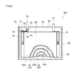
- FIG. 2 is a diagram schematically showing a cross-sectional structure taken along line II-II of the sealed lithium secondary battery of FIG.
- FIG. 3 is a schematic diagram illustrating a configuration of a wound electrode body of a sealed lithium secondary battery according to an embodiment of the present invention.
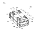
- FIG. 4 is a perspective view schematically showing an assembled battery in which a plurality of sealed lithium secondary batteries (unit cells) according to an embodiment of the present invention are combined.
- FIG. 5 is a side view showing a vehicle (automobile) including an assembled battery according to an embodiment of the present invention.
- FIG. 6 is a graph showing the relationship between the viscosity (mPa ⁇ sec) of the electrolyte and the temperature (° C.).
- the “lithium secondary battery” refers to a secondary battery that uses lithium ions as electrolyte ions and is charged and discharged by the movement of charges accompanying the lithium ions between the positive and negative electrodes.
- a power storage element generally referred to as a lithium ion battery (or a lithium ion secondary battery), a lithium polymer battery, a lithium ion capacitor, or the like is a typical example included in the lithium secondary battery in this specification.
- the “active material” refers to a substance (compound) involved in power storage on the positive electrode side or the negative electrode side. That is, it refers to a substance that is involved in the insertion and extraction of electrons during battery charge / discharge.
- the “overcharge state” refers to a state in which the charge depth (SOC) exceeds 100%.
- SOC is a charge state (that is, a fully charged state) in which an upper limit voltage is obtained in an operating voltage range that can be reversibly charged and discharged, and a charge state (that is, a lower limit voltage is obtained).
- the state of not being charged shows the state of charge when 0%.
- a positive electrode active material, a conductive material, a binder (binder) and the like are mixed in an appropriate solvent to form a slurry (a paste or an ink) (Hereinafter referred to as “positive electrode mixture slurry”), and the slurry is applied onto the positive electrode current collector to form a positive electrode mixture layer (also referred to as a positive electrode active material layer).
- a slurry a paste or an ink
- positive electrode mixture slurry a paste or an ink
- the positive electrode active material layer also referred to as a positive electrode active material layer
- the formed form is used.
- the positive electrode active material, the conductive material, and the binder may be kneaded at a time, or may be kneaded stepwise in several steps.
- the solid content concentration (NV) of the positive electrode mixture slurry can be about 50% to 75% (preferably 55% to 65%, more preferably 55% to 60%).
- the positive electrode mixture slurry is applied to one or both surfaces of the positive electrode current collector with a conventionally known coating device (for example, a slit coater, a die coater, a comma coater, a gravure coater, etc.).
- a conventionally known coating device for example, a slit coater, a die coater, a comma coater, a gravure coater, etc.
- a method of applying an appropriate amount using and drying can be preferably employed.
- Examples of the material for the positive electrode current collector include aluminum, nickel, titanium, and stainless steel.
- the shape of the current collector can be different depending on the shape of the battery to be constructed, and is not particularly limited.
- a rod-like body, a plate-like body, a foil-like body, a net-like body, or the like can be used.
- a foil-like body is mainly used.
- the thickness of the foil-shaped current collector is not particularly limited, but about 5 ⁇ m to 50 ⁇ m (more preferably 8 ⁇ m to 30 ⁇ m) can be preferably used in consideration of the capacity density of the battery and the strength of the current collector.
- an oxide containing lithium and a transition metal element as constituent metal elements such as lithium nickel oxide (for example, LiNiO 2 ), lithium cobalt oxide (for example, LiCoO 2 ), and lithium manganese oxide (for example, LiMn 2 O 4 ).
- LiNiO 2 lithium nickel oxide
- LiCoO 2 lithium cobalt oxide
- LiMn 2 O 4 lithium manganese oxide
- phosphates including lithium and transition metal elements such as lithium manganese phosphate (LiMnPO 4 ) and lithium iron phosphate (LiFePO 4 ) as constituent metal elements.
- a positive electrode active material (typical) mainly composed of a lithium nickel cobalt manganese composite oxide (for example, LiNi 1/3 Co 1/3 Mn 1/3 O 2 ) having a layered structure represented by the general formula: LiNiCoMnO 2
- the positive electrode active material substantially consisting of lithium nickel cobalt manganese composite oxide is preferably used because of its excellent thermal stability and high energy density.
- the proportion of the positive electrode active material in the entire positive electrode mixture layer is typically about 50% by mass or more (typically 70% to 99% by mass), and about 80% by mass. % To 99% by mass is preferable.
- the lithium nickel cobalt manganese composite oxide is an oxide having Li, Ni, Co, and Mn as constituent metal elements, and at least one other metal element (Li, Ni, Co, and Mn) in addition to Li, Ni, Co, and Mn.
- the meaning also includes oxides containing transition metal elements and / or typical metal elements other than Ni, Co, and Mn.
- Such metal elements include, for example, magnesium (Mg), calcium (Ca), strontium (Sr), titanium (Ti), zirconium (Zr), vanadium (V), niobium (Nb), chromium (Cr), molybdenum (Mo ), Tungsten (W), iron (Fe), rhodium (Rh), palladium (Pb), platinum (Pt), copper (Cu), zinc (Zn), boron (B), aluminum (Al), gallium (Ga) ), Indium (In), tin (Sn), lanthanum (La), and cerium (Ce).
- the amount of the substitutional constituent element is not particularly limited.
- a lithium transition metal oxide typically in particulate form
- a lithium transition metal oxide powder prepared by a conventionally known method can be used as it is.
- the particle size of the powder is not particularly limited, but can be, for example, about 1 ⁇ m to 25 ⁇ m (preferably 2 ⁇ m to 10 ⁇ m).
- particle size means a particle size corresponding to 50% cumulative from the fine particle side in a volume-based particle size distribution measured by particle size distribution measurement based on a general laser diffraction / light scattering method. D 50 particle diameter, also referred to as median diameter).
- the solvent one or more of the solvents conventionally used in lithium secondary batteries can be used without any particular limitation.
- a solvent is roughly classified into an aqueous solvent and an organic solvent.
- the organic solvent include amide, alcohol, ketone, ester, amine, ether, nitrile, cyclic ether, and aromatic hydrocarbon.
- N-methyl-2-pyrrolidone N, N-dimethylformamide (DMF), N, N-dimethylacetamide, 2-propanol, ethanol, methanol, acetone, methyl ethyl ketone, methyl propenoate, Cyclohexanone, methyl acetate, ethyl acetate, methyl acrylate, diethyltriamine, N, N-dimethylaminopropylamine, acetonitrile, ethylene oxide, tetrahydrofuran (THF), dioxane, benzene, toluene, ethylbenzene, xylene dimethyl sulfoxide (DMSO), dichloromethane, Examples thereof include trichloromethane and dichloroethane, and N-methyl-2-pyrrolidone (NMP) can be preferably used.
- NMP N-methyl-2-pyrrolidone
- DMF N-dimethylformamide
- the aqueous solvent is preferably water or a mixed solvent mainly composed of water.
- the solvent other than water constituting the mixed solvent one or more organic solvents (lower alcohol, lower ketone, etc.) that can be uniformly mixed with water can be appropriately selected and used.
- a particularly preferable example is an aqueous solvent (for example, water) substantially consisting of water.
- the conductive material one kind or two or more kinds of substances conventionally used in lithium secondary batteries can be used without any particular limitation.
- carbon black for example, acetylene black, furnace black, ketjen black, channel black, lamp black, thermal black, etc.
- coke graphite (natural graphite and modified products thereof, artificial graphite), carbon fiber (PAN-based, 1 type or 2 types or more selected from carbon materials, such as a pitch type
- metal fibers eg, Al, SUS, etc.
- conductive metal powders eg, Ag, Ni, Cu, etc.
- metal oxides eg, ZnO, SnO 2, etc.
- a preferable conductive material is carbon black (typically acetylene black) having a small particle size and a large specific surface area.
- the proportion of the conductive material in the entire positive electrode mixture layer can be, for example, approximately 0.1% by mass to 15% by mass, and approximately 1% by mass to 10% by mass (more preferably Is preferably 2 mass% to 6 mass%).
- the binder is a compound that can be uniformly dissolved or dispersed in the above-described solvent, and one or more kinds of substances conventionally used in lithium secondary batteries can be used without any particular limitation.
- a polymer material that is dispersed or dissolved in an organic solvent is preferably employed.
- the polymer material include polyvinylidene fluoride (PVdF), polyvinylidene chloride (PVdC), polyethylene oxide (PEO), and the like.
- a polymer material that is dissolved or dispersed in water can be preferably employed.
- examples of such polymer materials include cellulose polymers, fluorine resins, vinyl acetate copolymers, rubbers, and the like. More specifically, carboxymethylcellulose (CMC), hydroxypropylmethylcellulose (HPMC), polyvinyl alcohol (PVA), polytetrafluoroethylene (PTFE), tetrafluoroethylene-hexafluoropropylene copolymer (FEP), styrene butadiene rubber (SBR), acrylic acid-modified SBR resin (SBR latex), and the like.
- the proportion of the binder in the entire positive electrode mixture layer can be, for example, 0.1% by mass to 10% by mass (preferably 1% by mass to 5% by mass).
- the positive electrode mixture slurry prepared here has various additives (for example, an inorganic compound that generates gas during overcharge and a material that can function as a dispersant, as long as the effects of the present invention are not significantly impaired. ) Etc. can also be added.
- the inorganic compound that generates a gas during the overcharge include carbonates, oxalates, and nitrates.
- lithium carbonate and lithium oxalate are preferably used.
- the dispersant a high molecular compound having a hydrophobic chain and a hydrophilic group (for example, alkali salt, typically sodium salt), an anionic compound having sulfate, sulfonate, phosphate, etc.
- CMC carboxymethyl cellulose
- methyl cellulose methyl cellulose
- ethyl cellulose hydroxyethyl cellulose
- hydroxypropyl cellulose butyral
- polyvinyl alcohol modified polyvinyl alcohol
- polyethylene oxide polyvinyl pyrrolidone
- polyacrylic acid polycarboxylic acid and the like
- the positive electrode mixture layer is dried by an appropriate drying means, and the solvent contained in the positive electrode mixture slurry is removed.
- an appropriate drying means natural drying, hot air, low-humidity air, vacuum, infrared rays, far infrared rays, electron beams, or the like can be used alone or in combination.
- the thickness of the positive electrode mixture layer and the like can be appropriately determined by applying press treatment (for example, various conventionally known press methods such as a roll press method and a flat plate press method). The density can be adjusted. When the density of the positive electrode mixture layer formed on the positive electrode current collector is extremely low, the capacity per unit volume may decrease.
- the density of the positive electrode mixture layer is, for example, 2.0 g / cm 3 or more (typically 2.5 g / cm 3 or more) and 4.2 g / cm 3 or less (typically 4. g / cm 3 or more). 0 g / cm 3 or less).
- a negative electrode active material and a binder or the like are mixed in a suitable solvent to form a slurry (including paste and ink) compositions.
- a slurry including paste and ink
- negative electrode mixture slurry is prepared, and the slurry is applied onto the negative electrode current collector to form a negative electrode mixture layer (also referred to as negative electrode active material layer).
- a method for forming the negative electrode mixture layer it is preferable to employ a method in which an appropriate amount of the negative electrode mixture slurry is applied to one or both surfaces of the negative electrode current collector and dried, as in the case of the positive electrode described above. it can.
- Examples of the material for the negative electrode current collector include copper, nickel, titanium, and stainless steel.
- this form is not specifically limited, A rod-shaped body, a plate-shaped body, a foil-shaped body, a net-like body, etc. can be used.
- a battery having a wound electrode body to be described later uses a foil shape.
- the thickness of the foil-shaped current collector is not particularly limited, but about 5 ⁇ m to 50 ⁇ m (more preferably 8 ⁇ m to 30 ⁇ m) can be preferably used in consideration of the capacity density of the battery and the strength of the current collector.
- one type or two or more types of materials conventionally used in lithium secondary batteries can be used without any particular limitation.
- natural graphite (graphite) and its modified products and graphite (artificial graphite) such as artificial graphite manufactured from petroleum or coal-based materials; hard carbon (non-graphitizable carbon), soft carbon (graphitizable carbon), Carbon nanotubes and other carbon materials having a graphite structure (layered structure) at least partially, such as carbon nanotubes; metal oxides such as lithium titanium composite oxides; tin (Sn), silicon (Si) and lithium alloys, etc.
- graphite graphite
- its modified products and graphite artificial graphite manufactured from petroleum or coal-based materials
- hard carbon non-graphitizable carbon
- soft carbon graphitizable carbon
- metal oxides such as lithium titanium composite oxides
- a graphitic carbon material (typically, graphite) that can obtain a large capacity can be preferably used.
- the proportion of the negative electrode active material in the whole negative electrode mixture layer is not particularly limited, but it is usually suitably about 50% by mass or more, preferably about 90% by mass to 99% by mass (for example, about 95% by mass to 99% by mass).
- an appropriate material can be selected from the polymer materials exemplified as the binder for the positive electrode mixture layer.
- SBR styrene butadiene rubber
- PVdF polyvinylidene fluoride
- PTFE polytetrafluoroethylene
- the proportion of the binder in the entire negative electrode mixture layer may be appropriately selected according to the type and amount of the negative electrode active material, and is, for example, 1% by mass to 10% by mass (preferably 2% by mass to 5% by mass). Can do.
- various additives for example, an inorganic compound that generates gas during overcharge, a polymer material that can function as a dispersant), a conductive material, and the like can be used as appropriate.
- the negative electrode After the drying of the negative electrode mixture slurry, similarly to the case of the positive electrode, the negative electrode is appropriately subjected to press treatment (for example, various conventionally known pressing methods such as a roll press method and a flat plate pressing method can be adopted).
- press treatment for example, various conventionally known pressing methods such as a roll press method and a flat plate pressing method can be adopted.
- the thickness and density of the composite material layer can be adjusted.
- the density of the negative electrode mixture layer is, for example, 1.1 g / cm 3 or more (typically 1.2 g / cm 3 or more, for example, 1.3 g / cm 3 or more), and 1.5 g / cm 3 or less. (Typically 1.49 g / cm 3 or less).
- the above positive electrode and negative electrode are laminated to produce an electrode body.
- the shape of the electrode body is not particularly limited.
- a long positive electrode current collector layer having a predetermined width is formed on the long positive electrode current collector along the longitudinal direction of the current collector.
- a positive electrode and a long negative electrode in which a negative electrode mixture layer having a predetermined width is formed along the longitudinal direction of the current collector are laminated on the long negative electrode current collector.
- the battery disclosed herein can stably generate a desired amount of gas under a wide range of temperature environments, the current interruption mechanism can be more reliably operated even in such a case.
- the case is provided with a current interruption mechanism (a mechanism capable of interrupting the current in response to an increase in the case internal pressure caused by the generation of the gas when the battery is overcharged) as a safety mechanism.
- a current interruption mechanism a mechanism capable of interrupting the current in response to an increase in the case internal pressure caused by the generation of the gas when the battery is overcharged
- a separator is interposed between the positive electrode and the negative electrode.
- the separator various porous sheets similar to those conventionally used for lithium secondary batteries can be used.
- the separator is made of a resin such as polyethylene (PE), polypropylene (PP), polyester, cellulose, or polyamide.
- PE polyethylene
- PP polypropylene
- polyester polyester
- cellulose or polyamide.
- a porous resin sheet film, nonwoven fabric, etc.
- Such a porous resin sheet may have a single layer structure, or may have a two or more layers structure (for example, a three-layer structure in which a PP layer is laminated on both sides of a PE layer).
- the electrolyte may also serve as a separator.
- the battery case materials and shapes used in conventional lithium secondary batteries can be used.
- the material of the case include relatively light metal materials such as aluminum and steel, and resin materials such as PPS and polyimide resin.
- the shape (outer shape of the container) is not particularly limited, and may be, for example, a cylindrical shape, a rectangular shape, a rectangular parallelepiped shape, a coin shape, a bag shape, or the like.
- the electrolyte one kind or two or more kinds similar to the nonaqueous electrolyte used in the conventional lithium secondary battery can be used without any particular limitation.
- a non-aqueous electrolyte typically has a composition in which a supporting salt (lithium salt) is contained in an appropriate non-aqueous solvent.
- a polymer is added to a liquid electrolyte to form a solid (typically a so-called gel).
- Electrolyte As the non-aqueous solvent, aprotic solvents such as carbonates, esters, ethers, nitriles, sulfones, and lactones can be used.
- ethylene carbonate (EC), propylene carbonate (PC), diethyl carbonate (DEC), dimethyl carbonate (DMC), ethyl methyl carbonate (EMC), 1,2-dimethoxyethane, 1,2-diethoxyethane, tetrahydrofuran examples include 2-methyltetrahydrofuran, dioxane, 1,3-dioxolane, diethylene glycol dimethyl ether, ethylene glycol dimethyl ether, acetonitrile, propionitrile, nitromethane, N, N-dimethylformamide, dimethyl sulfoxide, sulfolane, and ⁇ -butyrolactone.
- a non-aqueous solvent mainly composed of carbonates is preferable because it can form a coating (SEI: Solid Electrolyte Interface) on the surface of the negative electrode active material, and in particular, EC having a high relative dielectric constant and a high standard oxidation potential (that is, DMC and EMC having a wide potential window can be preferably used.
- the nonaqueous solvent contains one or more carbonates, and the total volume of these carbonates is 60% by volume or more (more preferably 75% by volume or more, and further preferably 90% by volume or more) of the total volume of the nonaqueous solvent. And a non-aqueous solvent occupying substantially 100% by volume) is preferably used.
- Examples of the supporting salt include LiPF 6 , LiBF 4 , LiClO 4 , LiN (SO 2 CF 3 ) 2 , LiN (SO 2 C 2 F 5 ) 2 , LiCF 3 SO 3 , LiC 4 F 9 SO 3 , LiC ( SO 2 CF 3 ) 3 , LiClO 4 and the like are exemplified. Of these, LiPF 6 is preferably used.
- the concentration of the electrolyte is not particularly limited, but if the concentration of the electrolyte is too low, the amount of lithium ions contained in the electrolyte is insufficient, and the ionic conductivity tends to decrease.
- a nonaqueous electrolyte containing an electrolyte at a concentration of about 0.1 mol / L to 5 mol / L (preferably about 0.8 mol / L to 1.5 mol / L) is preferably used.
- the electrolyte of the sealed lithium secondary battery disclosed herein exceeded a predetermined battery voltage with a compound (viscosity modifier) that can suppress a decrease in the viscosity of the electrolyte accompanying a temperature increase in a temperature range of 100 ° C. or lower.
- a compound viscosity modifier
- an aromatic compound capable of generating hydrogen gas is added.
- a viscosity modifier included, a decrease in the viscosity of the electrolyte can be suppressed in a temperature range higher than room temperature (typically 20 ° C. or higher). Therefore, even in a high temperature environment (typically 50 ° C. to 100 ° C., for example, 50 ° C.
- the aromatic compound as an overcharge inhibitor is suitably decomposed, and the desired gas is more stable than in the past. Amount can be generated. Since the generation of such gas may cause a pressure increase in the battery case, the sealed lithium secondary battery disclosed herein has a wider temperature environment (typically 100 ° C. or less, for example, 0 ° C.). The current interruption mechanism can be more reliably operated at a temperature between 0 ° C. and 70 ° C.
- the electrolyte preferably has a ratio (V 60 / V 25 ) of a viscosity (V 25 ) at 25 ° C. to a viscosity (V 60 ) at 60 ° C. of 0.8 or more and 10 or less.
- viscosity refers to a viscosity (mPa ⁇ sec) measured with a general rheometer at a shear rate of 100 s ⁇ 1 unless otherwise specified. The method for measuring the viscosity will be described in detail in Examples described later.
- a compound (viscosity modifier) that can suppress a decrease in the viscosity of the electrolyte accompanying an increase in temperature it is a compound that uniformly dissolves or disperses in the electrolyte used, and the viscosity increases (gels) as the environmental temperature increases.
- One or two or more of the compounds to be included can be used as appropriate.
- Such a compound is not particularly limited, but for example, a polymer obtained from nature (natural polymer) by a known method or a process (typically physical or chemical modification) of the obtained polymer.
- a polymer compound in which a plurality of monosaccharides (monosaccharide and derivatives thereof) are bonded by a glucoside bond (for example, 10 or more) can be preferably used.
- the electrolyte contains a polysaccharide, the effect of the present invention (improvement of safety under a wide temperature environment) can be suitably exhibited while maintaining excellent battery performance (for example, high power density).
- the polysaccharide is excellent in biodegradability as it is used as a food additive, it is preferable from the viewpoint of safety and environmental protection.
- curdlan More specifically, curdlan, starch, dextrin, glucomannan, agarose, carrageenan, guar gum, locust bean gum, tragacanth gum, quinseed gum, xanthan gum, gum arabic, pullulan, agar, konjac mannan, etc.
- a curdlan (1,3-glucan) glucoside-bonded at the C1 and C3 positions of D-glucose can be preferably used.
- the qualitative analysis and quantitative analysis of the viscosity modifier contained in the electrolyte can be performed, for example, by a general high performance liquid chromatography (HPLC: High Performance Liquid Chromatography) method.
- the addition amount of the viscosity modifier is not particularly limited, but is, for example, 0.1% by mass or more (for example, 1% by mass or more) and 10% by mass or less (typically 10% by mass) with respect to 100% by mass of the electrolyte. Less than mass%, preferably 5 mass% or less).
- the aromatic compound as the overcharge inhibitor is suitably decomposed even in a high temperature environment, and the amount of gas necessary for reliably operating the current interrupting device can be obtained. Therefore, as shown in Examples described later, the effects of the present invention (that is, improvement in safety under a wide range of temperature environments) and excellent battery performance can be achieved at a high level.
- the molecular weight of the polymer compound is not particularly limited, but generally, when the weight average molecular weight (Mw) of the polymer compound used is extremely small, the viscosity is insufficient and dispersion becomes unstable. On the other hand, if the molecular weight of the polymer compound used is extremely large, the movement of lithium ions associated with the battery reaction is hindered, so that battery performance may be reduced (typically, battery resistance increases).
- the value of the weight average molecular weight (Mw) calculated using the formula (1) It can be 10,000 or more and 500,000 or less (preferably 50,000 or more and 300,000 or less).
- M i molecular weight of the i-th eluted component W i ; weight of the i-th eluted component W; total weight of the component H i ; peak height of the i-th eluted component
- Aromatic compounds are one type of substances conventionally used in lithium secondary batteries as long as the oxidation potential is equal to or higher than the operating voltage of the lithium secondary battery and decomposes in an overcharged state to generate gas.
- two or more kinds can be used without any particular limitation. Specifically, for example, when the battery is used in an operating range of 3.0 V to 4.1 V, an oxidation potential that is higher by about the above operating upper limit voltage +0.1 V (typically +0.2 V, for example +0.3 V). It is preferable that two or more compounds having different oxidation potentials are mixed.
- biphenyl compounds alkylbiphenyl compounds, cycloalkylbenzene compounds, alkylbenzene compounds, organic phosphorus compounds, fluorine atom-substituted aromatic compounds, carbonate compounds, cyclic carbamate compounds, and alicyclic hydrocarbons.
- biphenyl cyclohexylbenzene (CHB), trans-butylcyclohexylbenzene, cyclopentylbenzene, t-butylbenzene, t-aminobenzene, terphenyl, 2-fluorobiphenyl, 3-fluorobiphenyl, 4 -Fluorobiphenyl, 4,4'-difluorobiphenyl, o-cyclohexyl fluorobenzene, p-cyclohexyl fluorobenzene, tris- (t-butylphenyl) phosphate, phenyl fluoride, 4-fluorophenyl acetate, diphenyl carbonate, methylphenyl carbonate , Bicterary butyl phenyl carbonate, diphenyl ether, dibenzofuran and the like.
- an aromatic compound such as cyclohexylbenzene (CHB) or biphenyl (BP) having a relatively low oxidation potential of about 4.5 to 4.6 V is preferable. It can be used, and it is more preferable to mix both.
- the amount of the aromatic compound added to the electrolyte is not particularly limited. However, if the amount added is too small, the amount of gas generated during overcharge decreases, and the current interrupt mechanism may not operate normally. Moreover, if an excessive amount that places importance on safety is added, battery performance may be reduced (for example, increase in battery resistance or deterioration in cycle characteristics). Therefore, the amount of the aromatic compound added to 100% by mass of the electrolyte is, for example, about 0.1% by mass or more (typically 0.5% by mass or more, for example, 1% by mass or more), and 5% by mass or less ( Typically, it can be 4% by mass or less, for example, 3% by mass or less, preferably 2% by mass or less.
- hydrogen gas can be generated more stably than in the prior art even in a high-temperature environment (for example, 50 ° C. to 70 ° C.), so that the current interrupting device can be operated more reliably. Therefore, since the amount of the overcharge inhibitor added can be reduced as compared with the conventional case, excellent battery performance (for example, reduction in battery resistance) and the effect of the present invention (that is, improvement in safety under a wide temperature environment) ) At a higher level.
- a high-temperature environment for example, 50 ° C. to 70 ° C.
- the current interrupting mechanism is not particularly limited as long as the current can be interrupted according to the increase in pressure in the battery case (that is, using the increase in internal pressure as a trigger for operation), and the current provided in this type of battery is not limited.
- a mechanism similar to any conventionally known blocking mechanism can be appropriately employed.
- a configuration shown in FIG. 2 described later can be preferably used. In such a configuration, when the internal pressure of the battery case rises, the member constituting the conductive path from the electrode terminal to the electrode body is deformed, and the conductive path is cut by being separated from the other.
- a flatly wound electrode body (winded electrode body) and a non-aqueous electrolyte are shown in a flat rectangular parallelepiped (box) container as an example, and a schematic configuration is shown in FIGS.
- FIGS. In the following drawings, members / parts having the same action are denoted by the same reference numerals, and redundant description may be omitted or simplified.
- the dimensional relationship (length, width, thickness, etc.) in each figure does not reflect the actual dimensional relationship.
- FIG. 1 is a perspective view schematically showing the outer shape of a sealed lithium secondary battery 100 according to an embodiment of the present invention.
- FIG. 2 is a diagram schematically showing a cross-sectional structure taken along line II-II of the sealed lithium secondary battery shown in FIG.
- the sealed lithium secondary battery 100 according to the present embodiment includes a wound electrode body 80 and a hard case (outer container) 50.
- the hard case 50 includes a flat cuboid (box-shaped) hard case main body 52 having an open upper end, and a lid 54 that closes the opening.
- a positive electrode terminal 70 that is electrically connected to the positive electrode sheet of the wound electrode body 80 and a negative electrode terminal 72 that is electrically connected to the negative electrode sheet of the electrode body are provided on the upper surface of the hard case 50 (that is, the lid 54).
- the lid 54 is provided with a safety valve 55 for discharging gas generated inside the battery case to the outside of the case, similarly to the hard case of the conventional sealed lithium secondary battery.
- the safety valve 55 is typically set to be opened at a pressure higher than the pressure at which the current interrupt mechanism 30 operates.
- a long positive electrode sheet 10 and a long negative electrode sheet 20 are long separators 40A and 40B.
- the electrode body (winding electrode body) 80 wound in a flat shape is accommodated together with a non-aqueous electrolyte (not shown).
- the positive electrode sheet 10 is formed such that the positive electrode mixture layer 14 is not provided (or removed) at one end portion along the longitudinal direction, and the positive electrode current collector 12 is exposed.
- the wound negative electrode sheet 20 is not provided with (or removed from) the negative electrode mixture layer 24 at one end along the longitudinal direction, so that the negative electrode current collector 22 is exposed. Is formed.
- a positive electrode current collector plate 74 is attached to the exposed end of the positive electrode current collector 12, and a negative electrode current collector plate 76 is attached to the exposed end of the negative electrode current collector 22. Each is electrically connected to the negative terminal 72.
- a current interrupting mechanism 30 that is activated by an increase in the internal pressure of the battery case is provided inside the battery case 50.
- the current interruption mechanism 30 only needs to be configured to cut a conductive path (for example, a charging path) from at least one electrode terminal to the electrode body 80 when the internal pressure of the battery case 50 increases, and has a specific shape. It is not limited to.
- the current interruption mechanism 30 is provided between the positive electrode terminal 70 fixed to the lid body 54 and the electrode body 80, and reaches from the positive electrode terminal 70 to the electrode body 80 when the internal pressure of the battery case 50 rises.
- the conductive path is configured to be cut.
- the current interrupt mechanism 30 may include a first member 32 and a second member 34, for example.
- the first member 32 is a deformed metal plate
- the second member 34 is a connection metal plate joined to the deformed metal plate 32.
- the deformed metal plate (first member) 32 has an arch shape in which a central portion is curved downward, and a peripheral portion thereof is connected to the lower surface of the positive electrode terminal 70 via a current collecting lead terminal 35. Further, the tip of the curved portion 33 of the deformed metal plate 32 is joined to the upper surface of the connection metal plate 34.
- a positive current collector plate 74 is joined to the lower surface (back surface) of the connection metal plate 34, and the positive current collector plate 74 is connected to the positive electrode 10 of the electrode body 80. In this way, a conductive path from the positive electrode terminal 70 to the electrode body 80 is formed.
- the current interrupt mechanism 30 includes an insulating case 38 made of plastic or the like.
- the insulating case 38 is provided so as to surround the deformed metal plate 32 and hermetically seals the upper surface of the deformed metal plate 32.
- the internal pressure of the battery case 50 does not act on the upper surface of the hermetically sealed curved portion 33.
- the insulating case 38 has an opening into which the curved portion 33 of the deformed metal plate 32 is fitted, and the lower surface of the curved portion 33 is exposed from the opening to the inside of the battery case 50.
- the internal pressure of the battery case 50 acts on the lower surface of the curved portion 33 exposed inside the battery case 50.
- the current interrupt mechanism 30 having such a configuration, when the internal pressure of the battery case 50 increases, the internal pressure acts on the lower surface of the curved portion 33 of the deformed metal plate 32, and the curved portion 33 curved downward is pushed upward.
- the upward push of the curved portion 33 increases as the internal pressure of the battery case 50 increases.
- the curved portion 33 is turned upside down and deformed so as to bend upward. Due to the deformation of the curved portion 33, the joint point 36 between the deformed metal plate 32 and the connection metal plate 34 is cut. As a result, the conductive path from the positive electrode terminal 70 to the electrode body 80 is cut, and the overcharge current is cut off.
- the electric current interruption mechanism 30 may be provided not only in the positive electrode terminal 70 side but in the negative electrode terminal 72 side.
- the current interrupt mechanism 30 is not limited to the mechanical cutting accompanied by the deformation of the deformed metal plate 32 described above.
- the internal pressure of the battery case 50 is detected by a sensor, and the internal pressure detected by the sensor sets the set pressure.
- An external circuit that cuts off the charging current when exceeded can be provided as a current cut-off mechanism.
- FIG. 3 is a diagram schematically showing a long sheet structure (electrode sheet) in a stage before assembling the wound electrode body 80.
- a positive electrode sheet 10 in which a positive electrode mixture layer 14 is formed along the longitudinal direction on one or both surfaces (typically both surfaces) of a long positive electrode current collector 12, and a long negative electrode current collector 22.
- the negative electrode sheet 20 on which the negative electrode mixture layer 24 is formed along the longitudinal direction on one side or both sides (typically both sides) is overlapped with the long separators 40A and 40B and wound in the longitudinal direction.
- a wound electrode body is prepared.
- a flat wound electrode body 80 is obtained by squashing and winding the wound electrode body from the side surface direction.
- a battery including a wound electrode body has a high capacity among lithium secondary batteries, it is particularly important to improve reliability (for example, safety measures in the case of malfunction). According to the technology disclosed herein, the safety of such a battery (for example, safety when an overcharge or an internal short-circuit occurs) can be improved as compared with the related art.
- FIG. 4 shows an example of an assembled battery (typically, an assembled battery in which a plurality of single cells are connected in series and / or in parallel) 200 including a plurality of the sealed lithium secondary batteries (single cells) 100.
- the assembled battery 200 includes a plurality of (typically 10 or more, preferably about 10 to 30, for example, 20) sealed lithium secondary batteries (unit cells) 100, each having a positive electrode terminal 70 and a negative electrode. While the terminals 72 are inverted one by one so as to be alternately arranged, the wide surfaces of the hard case 50 are arranged in the facing direction (stacking direction).
- a cooling plate 110 having a predetermined shape is sandwiched between the arranged cells 100.
- the cooling plate 110 functions as a heat dissipating member for efficiently dissipating heat generated in each unit cell 100 during use, and preferably a cooling fluid (typically between the unit cells 100). Air) (for example, a shape in which a plurality of parallel grooves extending vertically from one side of the rectangular cooling plate to the opposite side are provided on the surface).
- a cooling plate made of metal having good thermal conductivity or lightweight and hard polypropylene or other synthetic resin is suitable.
- a pair of end plates (restraint plates) 120 are arranged at both ends of the unit cells 100 and the cooling plate 110 arranged as described above.
- One or a plurality of sheet-like spacer members 150 as length adjusting means may be sandwiched between the cooling plate 110 and the end plate 120.
- the unit cell 100, the cooling plate 110, and the spacer member 150 arranged in the above manner are applied with a predetermined restraining pressure in the stacking direction by a fastening restraint band 130 attached so as to bridge between both end plates. It is restrained. More specifically, by tightening and fixing the end portion of the restraining band 130 to the end plate 120 with screws 155, the unit cells and the like are restrained so that a predetermined restraining pressure is applied in the arrangement direction.
- the sealed lithium secondary battery disclosed herein can be used for various applications, but is characterized by improved safety in a wide range of temperature environments (for example, 50 to 70 ° C.). Therefore, it can be particularly suitably used for applications that require high energy density and power density, and applications that can be used and / or left to stand at high temperatures. Therefore, a battery pack 200 formed by connecting a plurality of sealed lithium secondary batteries disclosed herein is a power source (drive power source) for a motor mounted on a vehicle 1 such as an automobile as shown in FIG. ) Can be preferably used. Although the kind of vehicle 1 is not specifically limited, Typically, a plug-in hybrid vehicle (PHV), a hybrid vehicle (HV), and an electric vehicle (EV) are mentioned. In addition, although the assembled battery 200 was used here, of course, the single battery 100 can also be used independently.
- a plug-in hybrid vehicle (PHV), a hybrid vehicle (HV), and an electric vehicle (EV) are mentioned.
- the assembled battery 200 was used here, of course, the single battery 100
- Example 1 A kneader (LiCoO 2 powder as a positive electrode active material powder, acetylene black as a conductive material, and polyvinylidene fluoride (PVdF) as a binder so that the mass ratio of these materials is approximately 93: 4: 3.
- the mixture was put into a planetary mixer and kneaded while adjusting the viscosity with N-methylpyrrolidone (NMP) so that the solid content concentration (NV) was about 50% by mass to prepare a positive electrode mixture slurry.
- NMP N-methylpyrrolidone
- This slurry was applied on a long aluminum foil (thickness 15 ⁇ m, width 78 mm, Sumitomo Light Metals 1085) as a positive electrode current collector with a width of 58.0 mm, and dried to form a positive electrode mixture layer. .
- the obtained positive electrode was roll-pressed to produce a sheet-like positive electrode (positive electrode sheet).
- the produced positive electrode sheet and negative electrode sheet were passed through two sheet-like separators (here, a single layer structure made of polyethylene (PE) having a width of 63.0 mm was used). And then rolled. The obtained wound electrode body was crushed from the side surface direction and crushed to produce a flat wound electrode body. Then, an aluminum positive electrode terminal is provided at the end of the positive electrode current collector (exposed portion of the current collector) of the electrode body, and a copper negative electrode terminal is provided at the end of the negative electrode current collector (exposed portion of the current collector). Each was joined by welding.
- PE polyethylene
- the wound electrode body is accommodated in a rectangular battery case (75 mm long, 120 mm wide, 15 mm high), a current interrupting mechanism (CID) is installed near the opening of the battery case, and a lid is attached And welded and sealed.
- a current interrupting mechanism CID
- EC ethylene carbonate
- EMC ethyl methyl carbonate
- DEC diethyl carbonate
- EMC EMC
- DEC 3: 5: 2
- curdlan trade name “curdlan NS” used as a viscosity modifier
- LiPF 6 as an electrolyte dissolved at a concentration of about 1.0 mol / L.
- Example 2 a sealed lithium secondary battery (Example 2) was constructed in the same manner as in Example 1 except that curdlan was contained in the electrolyte at a concentration of 1.0% by mass.
- Example 3 a sealed lithium secondary battery (Example 3) was constructed in the same manner as in Example 1 except that curdlan was contained in the electrolyte at a concentration of 5.0% by mass.
- Example 4 a sealed lithium secondary battery (Example 4) was constructed in the same manner as in Example 1 except that curdlan was contained in the electrolyte at a concentration of 10% by mass.
- Comparative Example 1 a sealed lithium secondary battery (Comparative Example 1) was constructed in the same manner as in Example 1 except that no curdlan was used.
- Comparative Example 2 a sealed lithium secondary battery (Comparative Example 2) was constructed in the same manner as in Example 4 except that biphenyl was not used.
- Comparative Example 3 a sealed lithium secondary battery (Comparative Example 3) was constructed in the same manner as Comparative Example 2 except that curdlan was contained in the electrolyte at a concentration of 20% by mass. Table 1 summarizes the characteristics of the battery constructed as described above.
- Each of the constructed batteries (Examples 1 to 4 and Comparative Examples 1 to 3) is charged with a constant current up to 4.1 V at a charging rate of 0.2 C under a temperature environment of 25 ° C.
- an aging process here, 4.1V at a charge rate of 0.2C
- the battery was charged at a constant current until it was held for 48 hours (left).
- Examples 1 to 3 that is, the addition ratio of the viscosity modifier is 0.1% by mass to 5% by mass
- the battery capacity is hardly decreased, and the effect of the present invention (the safety in a wide temperature environment) Improved) and excellent battery performance (for example, high power density) at a high level.
- the sealed lithium secondary battery disclosed here achieves both higher reliability (safety under a wide range of temperature environments) and superior battery performance (for example, reduced battery resistance) at a higher level. It is characterized by that. Therefore, in applications that require high energy density and output density, and applications that can be used and / or left to stand at high temperatures (for example, power sources (drive power supplies) for motors mounted on vehicles such as automobiles). It can be preferably used.
- the type of such a vehicle is not particularly limited, but typically includes a plug-in hybrid vehicle (PHV), a hybrid vehicle (HV), an electric vehicle (EV), and the like.
Abstract
Description
温度上昇に伴う電解質の粘度低下を抑制し得る化合物(以下、「粘度調整剤」という。)を含む場合、室温より高温(典型的には100℃以下、例えば25℃以上100℃以下)の温度域においても、過充電防止剤たる芳香族化合物のレドックスシャトル反応を抑えることができる。このため、高温環境下(例えば、50℃~70℃)においても、過充電防止剤たる芳香族化合物が好適に分解され、従来に比べ安定的に所望のガス量を発生させることができる。そして、かかるガスの発生により電池ケース内に圧力上昇を生じ得るため、電流遮断機構をより確実に作動させることができる。従って、ここで開示される密閉型リチウム二次電池では、従来に比べ信頼性(広範な温度域(典型的には100℃以下、例えば0℃~70℃)における安全性)を向上させることができる。 In order to achieve the above object, there is provided a sealed lithium secondary battery in which an electrode body including a positive electrode and a negative electrode and an electrolyte are accommodated in a predetermined battery case. The electrolyte includes a compound capable of suppressing a decrease in the viscosity of the electrolyte accompanying a temperature increase in a temperature range of 100 ° C. or less, an aromatic compound capable of generating hydrogen gas when exceeding a predetermined battery voltage, The battery case includes a current interrupting mechanism that operates when the pressure in the battery case increases with the generation of the hydrogen gas.
When a compound (hereinafter referred to as “viscosity modifier”) that can suppress a decrease in the viscosity of the electrolyte accompanying a temperature rise is included, the temperature is higher than room temperature (typically 100 ° C. or lower, for example, 25 ° C. or higher and 100 ° C. or lower). Even in the region, the redox shuttle reaction of the aromatic compound as the overcharge inhibitor can be suppressed. For this reason, even in a high-temperature environment (for example, 50 ° C. to 70 ° C.), the aromatic compound as the overcharge inhibitor is suitably decomposed, and a desired gas amount can be generated more stably than in the past. And since generation | occurrence | production of this gas can produce a pressure rise in a battery case, a current interruption | blocking mechanism can be operated more reliably. Therefore, the sealed lithium secondary battery disclosed herein can improve reliability (safety in a wide temperature range (typically 100 ° C. or lower, for example, 0 ° C. to 70 ° C.)) as compared to the conventional case. it can.
粘度調整剤として多糖類を含む場合、本発明の効果(広範な温度環境下における安全性の向上)を効果的に発揮することができる。更に、多糖類は食品添加物として用いられるほど生分解性に優れているため、安全性や環境保護の観点からも好ましい。 A preferred embodiment of the sealed lithium secondary battery disclosed herein includes at least a polysaccharide as a compound that can suppress a decrease in the viscosity of the electrolyte accompanying the temperature increase.
When a polysaccharide is contained as a viscosity modifier, the effect of the present invention (improvement of safety under a wide temperature environment) can be effectively exhibited. Furthermore, since the polysaccharide is excellent in biodegradability as it is used as a food additive, it is preferable from the viewpoint of safety and environmental protection.
多糖類としてカードランを含む場合、本発明の効果をより一層高いレベルで発揮することができる。 A preferred embodiment of the sealed lithium secondary battery disclosed herein includes at least curdlan as the polysaccharide.
When curdlan is contained as a polysaccharide, the effect of the present invention can be exhibited at a higher level.
電解質の粘度が上記範囲にある場合、高温環境下においても過充電防止剤たる芳香族化合物のレドックスシャトル反応を好適に抑制し得る。このため、上記芳香族化合物の分解反応が促進され、電流遮断装置を確実に作動させるために必要な量の水素ガスを安定して得ることができる。従って、本発明の効果(即ち、広範な温度環境下における安全性の向上)をより効果的に発揮することができる。 As a preferred embodiment of the sealed lithium secondary battery disclosed herein, the electrolyte has a viscosity (V 25 ) at 25 ° C. and a viscosity at 60 ° C. measured at a shear rate of 100 s −1 by a rheometer. The ratio (V 60 / V 25 ) with the viscosity (V 60 ) is 0.8 or more and 10 or less.
When the viscosity of the electrolyte is within the above range, the redox shuttle reaction of the aromatic compound serving as the overcharge inhibitor can be suitably suppressed even in a high temperature environment. For this reason, the decomposition reaction of the aromatic compound is promoted, and an amount of hydrogen gas necessary for reliably operating the current interrupting device can be stably obtained. Therefore, the effect of the present invention (that is, improvement in safety under a wide range of temperature environments) can be exhibited more effectively.
粘度調整剤の添加量が上記範囲にある場合、高温環境下においても過充電防止剤たる芳香族化合物が好適に分解され、電流遮断装置を確実に作動させるために必要なガス量を得ることができる。更に、従来に比べ分解反応が促進されることで、上記化合物の添加量を低く抑えることができる。従って、本発明の効果(即ち、広範な温度環境下における安全性の向上)と、優れた電池性能(例えば、高い出力密度)と、を高いレベルで両立させることができる。 As a preferred embodiment of the sealed lithium secondary battery disclosed herein, the amount of the compound that can suppress the decrease in the viscosity of the electrolyte accompanying the temperature increase is 0.1 mass relative to 100 mass% of the electrolyte. % Or more and 10% by mass or less.
When the addition amount of the viscosity modifier is in the above range, the aromatic compound as the overcharge preventing agent is suitably decomposed even in a high temperature environment, and the amount of gas necessary for reliably operating the current interrupting device can be obtained. it can. Furthermore, since the decomposition reaction is accelerated as compared with the conventional case, the amount of the compound added can be kept low. Therefore, the effect of the present invention (that is, improvement in safety under a wide temperature environment) and excellent battery performance (for example, high power density) can be achieved at a high level.
シクロヘキシルベンゼンやビフェニルは、酸化電位が凡そ4.5V~4.6Vであるため、例えば凡そ4.1V~4.2Vを上限充電電圧とする電池では、過充電時に速やかに酸化分解され、水素ガスを発生し得る。このため、電流遮断機構をより迅速に作動させることができる。 As a preferable embodiment of the sealed lithium secondary battery disclosed herein, the aromatic compound includes cyclohexylbenzene and / or biphenyl.
Since cyclohexylbenzene and biphenyl have an oxidation potential of about 4.5 V to 4.6 V, for example, in a battery having an upper limit charging voltage of about 4.1 V to 4.2 V, it is rapidly oxidized and decomposed when overcharged, and hydrogen gas Can occur. For this reason, a current interruption mechanism can be operated more rapidly.
ここで開示される技術では、高温環境下(例えば、50℃~70℃)においても従来に比べ安定的に水素ガスを発生させることができるため、電流遮断装置をより確実に作動させ得る。従って、従来に比べ過充電防止剤の添加量を削減することができるため、本発明の効果(即ち、広範な温度環境下における安全性の向上)と優れた電池性能(例えば、電池抵抗の低減)とをより高いレベルで両立させることができる。 As a preferred embodiment of the sealed lithium secondary battery disclosed herein, the amount of the aromatic compound added is 0.5% by mass or more and 5% by mass or less with respect to 100% by mass of the electrolyte. It is done.
In the technique disclosed herein, hydrogen gas can be generated more stably than in the prior art even in a high-temperature environment (for example, 50 ° C. to 70 ° C.), so that the current interrupting device can be operated more reliably. Therefore, since the amount of the overcharge inhibitor added can be reduced as compared with the conventional case, the effect of the present invention (that is, improvement in safety under a wide temperature environment) and excellent battery performance (for example, reduction in battery resistance) ) At a higher level.
ここで開示される密閉型リチウム二次電池は、ここで開示される密閉型リチウム二次電池は、信頼性(広範な温度環境下における安全性)の向上と優れた電池性能(例えば、電池抵抗の低減)とを高いレベルで両立していることを特徴とする。従って、高いエネルギー密度や出力密度が要求される用途や、使用および/または放置環境が高温になり得る用途で特に好適に使用し得る。よって、例えば車両(典型的には、プラグインハイブリッド自動車(PHV)、ハイブリッド自動車(HV)、電気自動車(EV)のような電動機)に搭載されるモーター駆動のための動力源(駆動用電源)として好適に用いることができる。 Furthermore, the vehicle provided with the said assembled battery as a drive power supply by this invention is provided.
The sealed lithium secondary battery disclosed herein is improved in reliability (safety under a wide temperature environment) and excellent battery performance (for example, battery resistance). Reduction) at a high level. Therefore, it can be used particularly suitably in applications where high energy density and power density are required, and in applications where use and / or storage conditions can be high. Thus, for example, a power source (drive power source) for driving a motor mounted on a vehicle (typically, an electric motor such as a plug-in hybrid vehicle (PHV), a hybrid vehicle (HV), or an electric vehicle (EV)). Can be suitably used.
なお、本明細書において、「過充電状態」とは、充電深度(SOC:State of Charge)が100%を超えた状態をいう。SOCとは、可逆的に充放電可能な稼動電圧の範囲において、その上限となる電圧が得られる充電状態(即ち、満充電状態)を100%とし、下限となる電圧が得られる充電状態(即ち、充電されていない状態)を0%としたときの充電状態を示すものである。 In the present specification, the “lithium secondary battery” refers to a secondary battery that uses lithium ions as electrolyte ions and is charged and discharged by the movement of charges accompanying the lithium ions between the positive and negative electrodes. A power storage element generally referred to as a lithium ion battery (or a lithium ion secondary battery), a lithium polymer battery, a lithium ion capacitor, or the like is a typical example included in the lithium secondary battery in this specification. Further, in this specification, the “active material” refers to a substance (compound) involved in power storage on the positive electrode side or the negative electrode side. That is, it refers to a substance that is involved in the insertion and extraction of electrons during battery charge / discharge.
In the present specification, the “overcharge state” refers to a state in which the charge depth (SOC) exceeds 100%. The SOC is a charge state (that is, a fully charged state) in which an upper limit voltage is obtained in an operating voltage range that can be reversibly charged and discharged, and a charge state (that is, a lower limit voltage is obtained). , The state of not being charged) shows the state of charge when 0%.
正極合材スラリーを調製する方法としては、上記正極活物質と導電材とバインダとを一度に混練してもよく、何回かに分けて段階的に混練してもよい。特に限定されるものではないが、正極合材スラリーの固形分濃度(NV)は凡そ50%~75%(好ましくは55%~65%、より好ましくは55%~60%)とすることができる。また、正極合材層を形成する方法としては、上記正極合材スラリーを正極集電体の片面または両面に、従来公知の塗布装置(例えば、スリットコーター、ダイコーター、コンマコーター、グラビアコーター等)を用いて適量塗布し、乾燥させる方法を好ましく採用することができる。 As a positive electrode of the sealed lithium secondary battery disclosed herein, a positive electrode active material, a conductive material, a binder (binder) and the like are mixed in an appropriate solvent to form a slurry (a paste or an ink) (Hereinafter referred to as “positive electrode mixture slurry”), and the slurry is applied onto the positive electrode current collector to form a positive electrode mixture layer (also referred to as a positive electrode active material layer). The formed form is used.
As a method for preparing the positive electrode mixture slurry, the positive electrode active material, the conductive material, and the binder may be kneaded at a time, or may be kneaded stepwise in several steps. Although not particularly limited, the solid content concentration (NV) of the positive electrode mixture slurry can be about 50% to 75% (preferably 55% to 65%, more preferably 55% to 60%). . In addition, as a method of forming the positive electrode mixture layer, the positive electrode mixture slurry is applied to one or both surfaces of the positive electrode current collector with a conventionally known coating device (for example, a slit coater, a die coater, a comma coater, a gravure coater, etc.). A method of applying an appropriate amount using and drying can be preferably employed.
このようなリチウム遷移金属酸化物(典型的には粒子状)としては、例えば従来公知の方法で調製されるリチウム遷移金属酸化物粉末をそのまま使用することができる。かかる粉末の粒径は、特に限定するものではないが、例えば、凡そ1μm~25μm(好ましくは2μm~10μm)とすることができる。なお、本明細書において「粒径」とは一般的なレーザー回折・光散乱法に基づく粒度分布測定により測定した体積基準の粒度分布おいて、微粒子側からの累積50%に相当する粒径(D50粒径、メジアン径ともいう。)を示す。 Here, the lithium nickel cobalt manganese composite oxide is an oxide having Li, Ni, Co, and Mn as constituent metal elements, and at least one other metal element (Li, Ni, Co, and Mn) in addition to Li, Ni, Co, and Mn. The meaning also includes oxides containing transition metal elements and / or typical metal elements other than Ni, Co, and Mn. Such metal elements include, for example, magnesium (Mg), calcium (Ca), strontium (Sr), titanium (Ti), zirconium (Zr), vanadium (V), niobium (Nb), chromium (Cr), molybdenum (Mo ), Tungsten (W), iron (Fe), rhodium (Rh), palladium (Pb), platinum (Pt), copper (Cu), zinc (Zn), boron (B), aluminum (Al), gallium (Ga) ), Indium (In), tin (Sn), lanthanum (La), and cerium (Ce). The same applies to lithium nickel oxide, lithium cobalt oxide, and lithium manganese oxide. The amount of the substitutional constituent element is not particularly limited. For example, it is 0.1% by mass or more (typically 0.2% by mass with respect to a total of 100% by mass of the substitution element, Ni, Co, and Mn. % Or more, for example 0.3% by mass or more), and 1.0% by mass or less (typically 0.8% by mass or less, for example 0.7% by mass or less).
As such a lithium transition metal oxide (typically in particulate form), for example, a lithium transition metal oxide powder prepared by a conventionally known method can be used as it is. The particle size of the powder is not particularly limited, but can be, for example, about 1 μm to 25 μm (preferably 2 μm to 10 μm). In the present specification, “particle size” means a particle size corresponding to 50% cumulative from the fine particle side in a volume-based particle size distribution measured by particle size distribution measurement based on a general laser diffraction / light scattering method. D 50 particle diameter, also referred to as median diameter).
正極合材スラリーの乾燥後は、適宜プレス処理(例えば、ロールプレス法、平板プレス法等の従来公知の各種プレス方法を採用することができる。)を施すことによって、正極合材層の厚みや密度を調整することができる。正極集電体上に形成された正極合材層の密度が極端に低い場合は、単位体積当たりの容量が低下する虞がある。また、該正極合材層の密度が極端に高い場合は、特に大電流充放電時や低温下での充放電時において内部抵抗が上昇する傾向にある。このため、正極合材層の密度は、例えば2.0g/cm3以上(典型的には2.5g/cm3以上)であって、4.2g/cm3以下(典型的には4.0g/cm3以下)とすることができる。 Thereafter, the positive electrode mixture layer is dried by an appropriate drying means, and the solvent contained in the positive electrode mixture slurry is removed. As such a method, natural drying, hot air, low-humidity air, vacuum, infrared rays, far infrared rays, electron beams, or the like can be used alone or in combination.
After drying of the positive electrode mixture slurry, the thickness of the positive electrode mixture layer and the like can be appropriately determined by applying press treatment (for example, various conventionally known press methods such as a roll press method and a flat plate press method). The density can be adjusted. When the density of the positive electrode mixture layer formed on the positive electrode current collector is extremely low, the capacity per unit volume may decrease. Further, when the density of the positive electrode mixture layer is extremely high, the internal resistance tends to increase particularly during large current charge / discharge or charge / discharge at a low temperature. For this reason, the density of the positive electrode mixture layer is, for example, 2.0 g / cm 3 or more (typically 2.5 g / cm 3 or more) and 4.2 g / cm 3 or less (typically 4. g / cm 3 or more). 0 g / cm 3 or less).
その他、既に上述した各種添加剤(例えば、過充電時においてガスを発生させる無機化合物や、分散剤として機能し得るポリマー材料)や導電材等を適宜使用することができる。 As the binder, an appropriate material can be selected from the polymer materials exemplified as the binder for the positive electrode mixture layer. For example, styrene butadiene rubber (SBR), polyvinylidene fluoride (PVdF), polytetrafluoroethylene (PTFE) and the like are exemplified. The proportion of the binder in the entire negative electrode mixture layer may be appropriately selected according to the type and amount of the negative electrode active material, and is, for example, 1% by mass to 10% by mass (preferably 2% by mass to 5% by mass). Can do.
In addition, the above-described various additives (for example, an inorganic compound that generates gas during overcharge, a polymer material that can function as a dispersant), a conductive material, and the like can be used as appropriate.
該非水溶媒としては、カーボネート類、エステル類、エーテル類、ニトリル類、スルホン類、ラクトン類等の非プロトン性溶媒を用いることができる。例えば、エチレンカーボネート(EC)、プロピレンカーボネート(PC)、ジエチルカーボネート(DEC)、ジメチルカーボネート(DMC)、エチルメチルカーボネート(EMC)、1,2-ジメトキシエタン、1,2-ジエトキシエタン、テトラヒドロフラン、2-メチルテトラヒドロフラン、ジオキサン、1,3-ジオキソラン、ジエチレングリコールジメチルエーテル、エチレングリコールジメチルエーテル、アセトニトリル、プロピオニトリル、ニトロメタン、N,N-ジメチルホルムアミド、ジメチルスルホキシド、スルホラン、γ-ブチロラクトン等が挙げられる。例えば、カーボネート類を主体とする非水溶媒は、負極活物質表面に被膜(SEI:Solid Electrolyte Interphase)を形成し得るため好ましく、なかでも比誘電率の高いECや、標準酸化電位が高い(即ち、電位窓の広い)DMCおよびEMC等を好ましく用いることができる。例えば非水溶媒として一種または二種以上のカーボネート類を含み、それらカーボネート類の合計体積が非水溶媒全体の体積の60体積%以上(より好ましくは75体積%以上、さらに好ましくは90体積%以上であり、実質的に100体積%であってもよい。)を占める非水溶媒が好ましく用いられる。 As the electrolyte, one kind or two or more kinds similar to the nonaqueous electrolyte used in the conventional lithium secondary battery can be used without any particular limitation. Such a non-aqueous electrolyte typically has a composition in which a supporting salt (lithium salt) is contained in an appropriate non-aqueous solvent. However, a polymer is added to a liquid electrolyte to form a solid (typically a so-called gel). Electrolyte).
As the non-aqueous solvent, aprotic solvents such as carbonates, esters, ethers, nitriles, sulfones, and lactones can be used. For example, ethylene carbonate (EC), propylene carbonate (PC), diethyl carbonate (DEC), dimethyl carbonate (DMC), ethyl methyl carbonate (EMC), 1,2-dimethoxyethane, 1,2-diethoxyethane, tetrahydrofuran, Examples include 2-methyltetrahydrofuran, dioxane, 1,3-dioxolane, diethylene glycol dimethyl ether, ethylene glycol dimethyl ether, acetonitrile, propionitrile, nitromethane, N, N-dimethylformamide, dimethyl sulfoxide, sulfolane, and γ-butyrolactone. For example, a non-aqueous solvent mainly composed of carbonates is preferable because it can form a coating (SEI: Solid Electrolyte Interface) on the surface of the negative electrode active material, and in particular, EC having a high relative dielectric constant and a high standard oxidation potential (that is, DMC and EMC having a wide potential window can be preferably used. For example, the nonaqueous solvent contains one or more carbonates, and the total volume of these carbonates is 60% by volume or more (more preferably 75% by volume or more, and further preferably 90% by volume or more) of the total volume of the nonaqueous solvent. And a non-aqueous solvent occupying substantially 100% by volume) is preferably used.
なお、本明細書において「粘度」とは、特に言及しない限り、一般的なレオメータによって、せん断速度100s-1の条件で測定した粘度(mPa・sec)を示す。上記粘度の測定方法については、後述する実施例において詳細に述べる。 Further, the electrolyte preferably has a ratio (V 60 / V 25 ) of a viscosity (V 25 ) at 25 ° C. to a viscosity (V 60 ) at 60 ° C. of 0.8 or more and 10 or less. When the viscosity of the electrolyte is in the above range, the redox shuttle reaction of the aromatic compound serving as the overcharge inhibitor can be suppressed even in a high temperature environment. For this reason, the said aromatic compound is decomposed | disassembled suitably and the amount of hydrogen gas required in order to operate | move an electric current interruption apparatus reliably can be obtained stably. Therefore, the effect of the present invention (that is, improvement in safety under a wide range of temperature environments) can be exhibited more effectively.
In the present specification, “viscosity” refers to a viscosity (mPa · sec) measured with a general rheometer at a shear rate of 100 s −1 unless otherwise specified. The method for measuring the viscosity will be described in detail in Examples described later.
Mw=Σ(Mi×Wi)/W =Σ(Mi×Hi)/ΣHi (1)
ただし、Mi;i番目に溶出した成分の分子量
Wi;i番目に溶出した成分の重量
W ;成分の総重量
Hi;i番目に溶出した成分のピークの高さ Further, the molecular weight of the polymer compound is not particularly limited, but generally, when the weight average molecular weight (Mw) of the polymer compound used is extremely small, the viscosity is insufficient and dispersion becomes unstable. On the other hand, if the molecular weight of the polymer compound used is extremely large, the movement of lithium ions associated with the battery reaction is hindered, so that battery performance may be reduced (typically, battery resistance increases). Therefore, for example, from the molecular weight distribution obtained by GPC (Gel Permeation Chromatography) -RI (Refractive Index; differential refractive index detector), the value of the weight average molecular weight (Mw) calculated using the formula (1), It can be 10,000 or more and 500,000 or less (preferably 50,000 or more and 300,000 or less).
Mw = Σ (M i × W i ) / W = Σ (M i × H i ) / ΣH i (1)
Where M i ; molecular weight of the i-th eluted component W i ; weight of the i-th eluted component W; total weight of the component H i ; peak height of the i-th eluted component
具体的には、例えば、ビフェニル化合物、アルキルビフェニル化合物、シクロアルキルベンゼン化合物、アルキルベンゼン化合物、有機リン化合物、フッ素原子置換芳香族化合物、カーボネート化合物、環状カルバメート化合物、脂環式炭化水素等が挙げられる。より具体的には、ビフェニル(BP)、シクロヘキシルベンゼン(CHB)、trans-ブチルシクロヘキシルベンゼン、シクロペンチルベンゼン、t-ブチルベンゼン、t-アミノベンゼン、ターフェニル、2-フルオロビフェニル、3-フルオロビフェニル、4-フルオロビフェニル、4,4’-ジフルオロビフェニル、o-シクロヘキシルフルオロベンゼン、p-シクロヘキシルフルオロベンゼン、tris-(t-ブチルフェニル)ホスフェート、フェニルフルオライド、4-フルオロフェニルアセテート、ジフェニルカーボネート、メチルフェニルカーボネート、ビスターシャリーブチルフェニルカーボネート、ジフェニルエーテル、ジベンゾフラン等が挙げられる。例えば4.1V~4.2Vを上限充電電圧とする電池では、酸化電位が凡そ4.5~4.6Vと比較的低い、シクロヘキシルベンゼン(CHB)やビフェニル(BP)等の芳香族化合物を好ましく用いることができ、両者を混在させることがより好ましい。 Aromatic compounds are one type of substances conventionally used in lithium secondary batteries as long as the oxidation potential is equal to or higher than the operating voltage of the lithium secondary battery and decomposes in an overcharged state to generate gas. Alternatively, two or more kinds can be used without any particular limitation. Specifically, for example, when the battery is used in an operating range of 3.0 V to 4.1 V, an oxidation potential that is higher by about the above operating upper limit voltage +0.1 V (typically +0.2 V, for example +0.3 V). It is preferable that two or more compounds having different oxidation potentials are mixed.
Specific examples include biphenyl compounds, alkylbiphenyl compounds, cycloalkylbenzene compounds, alkylbenzene compounds, organic phosphorus compounds, fluorine atom-substituted aromatic compounds, carbonate compounds, cyclic carbamate compounds, and alicyclic hydrocarbons. More specifically, biphenyl (BP), cyclohexylbenzene (CHB), trans-butylcyclohexylbenzene, cyclopentylbenzene, t-butylbenzene, t-aminobenzene, terphenyl, 2-fluorobiphenyl, 3-fluorobiphenyl, 4 -Fluorobiphenyl, 4,4'-difluorobiphenyl, o-cyclohexyl fluorobenzene, p-cyclohexyl fluorobenzene, tris- (t-butylphenyl) phosphate, phenyl fluoride, 4-fluorophenyl acetate, diphenyl carbonate, methylphenyl carbonate , Bicterary butyl phenyl carbonate, diphenyl ether, dibenzofuran and the like. For example, in a battery having an upper limit charging voltage of 4.1 V to 4.2 V, an aromatic compound such as cyclohexylbenzene (CHB) or biphenyl (BP) having a relatively low oxidation potential of about 4.5 to 4.6 V is preferable. It can be used, and it is more preferable to mix both.
図1および図2に示すように、本実施形態に係る密閉型リチウム二次電池100は、捲回電極体80と、ハードケース(外容器)50とを備える。このハードケース50は、上端が開放された扁平な直方体形状(箱型)のハードケース本体52と、その開口部を塞ぐ蓋体54とを備える。ハードケース50の上面(すなわち蓋体54)には、捲回電極体80の正極シートと電気的に接続する正極端子70および該電極体の負極シートと電気的に接続する負極端子72が設けられている。また、蓋体54には、従来の密閉型リチウム二次電池のハードケースと同様に、電池ケース内部で発生したガスをケースの外部に排出するための安全弁55が備えられている。かかる安全弁55は、典型的には電流遮断機構30の作動する圧力以上で開放されるよう設定されている。 FIG. 1 is a perspective view schematically showing the outer shape of a sealed lithium
As shown in FIGS. 1 and 2, the sealed lithium
そして、隣接する単電池100間において、一方の正極端子70と他方の負極端子72とが、接続部材(バスバー)140によって電気的に接続されている。このように各単電池100を直列に接続することにより、所望する電圧の組電池200が構築されている。 A pair of end plates (restraint plates) 120 are arranged at both ends of the
Then, between the
<実施例1>
正極活物質粉末としてのLiCoO2粉末と、導電材としてのアセチレンブラックと、バインダとしてのポリフッ化ビニリデン(PVdF)とを、これら材料の質量比率が凡そ93:4:3となるよう、混練機(プラネタリーミキサー)に投入し、固形分濃度(NV)が凡そ50質量%となるようにN-メチルピロリドン(NMP)で粘度を調製しながら混練し、正極合材スラリーを調製した。このスラリーを、正極集電体としての長尺状のアルミニウム箔(厚み15μm、幅78mm、住友軽金属製1085)の上に幅58.0mmで塗布し、乾燥することで正極合材層を形成した。得られた正極をロールプレスし、シート状の正極(正極シート)を作製した。 [Construction of sealed lithium secondary battery]
<Example 1>
A kneader (LiCoO 2 powder as a positive electrode active material powder, acetylene black as a conductive material, and polyvinylidene fluoride (PVdF) as a binder so that the mass ratio of these materials is approximately 93: 4: 3. The mixture was put into a planetary mixer and kneaded while adjusting the viscosity with N-methylpyrrolidone (NMP) so that the solid content concentration (NV) was about 50% by mass to prepare a positive electrode mixture slurry. This slurry was applied on a long aluminum foil (thickness 15 μm, width 78 mm, Sumitomo Light Metals 1085) as a positive electrode current collector with a width of 58.0 mm, and dried to form a positive electrode mixture layer. . The obtained positive electrode was roll-pressed to produce a sheet-like positive electrode (positive electrode sheet).
かかる捲回電極体と、を角型の電池ケース(縦75mm、横120mm、高さ15mm)に収容し、該電池ケースの開口部付近に電流遮断機構(CID)を設置し、蓋体を装着して溶接し、封口した。かかる電池ケースの注液口から、調製した非水電解質(ここでは、エチレンカーボネート(EC)とエチルメチルカーボネート(EMC)とジエチルカーボネート(DEC)とを、EC:EMC:DEC=3:5:2の体積比で含む混合溶媒に、電解質としてのLiPF6を凡そ1.0mol/Lの濃度で溶解させたものを用いた。)と、粘度調整剤としてのカードラン(商品名「カードランNS」、キリン協和フーズ株式会社製)と、過充電防止剤としてのビフェニル(BP)とを、それぞれ0.1質量%と3.0質量%の濃度で含有させた電解質を用いた。)を120ml注入し、レーザー溶接して接合することにより定格容量4Ahの密閉型リチウム二次電池(実施例1)を5個構築した。 And the produced positive electrode sheet and negative electrode sheet were passed through two sheet-like separators (here, a single layer structure made of polyethylene (PE) having a width of 63.0 mm was used). And then rolled. The obtained wound electrode body was crushed from the side surface direction and crushed to produce a flat wound electrode body. Then, an aluminum positive electrode terminal is provided at the end of the positive electrode current collector (exposed portion of the current collector) of the electrode body, and a copper negative electrode terminal is provided at the end of the negative electrode current collector (exposed portion of the current collector). Each was joined by welding.
The wound electrode body is accommodated in a rectangular battery case (75 mm long, 120 mm wide, 15 mm high), a current interrupting mechanism (CID) is installed near the opening of the battery case, and a lid is attached And welded and sealed. From the injection hole of such a battery case, the prepared nonaqueous electrolyte (here, ethylene carbonate (EC), ethyl methyl carbonate (EMC), and diethyl carbonate (DEC), EC: EMC: DEC = 3: 5: 2). And a curdlan (trade name “curdlan NS”) used as a viscosity modifier, and a LiPF 6 as an electrolyte dissolved at a concentration of about 1.0 mol / L. , Manufactured by Kirin Kyowa Foods Co., Ltd.) and biphenyl (BP) as an overcharge inhibitor were used at concentrations of 0.1 mass% and 3.0 mass%, respectively. ) Was injected, and laser sealed and joined to form five sealed lithium secondary batteries (Example 1) with a rated capacity of 4 Ah.
実施例2では、カードランを1.0質量%の濃度で電解質に含有させたこと以外は実施例1と同様に、密閉型リチウム二次電池(実施例2)を構築した。 <Example 2>
In Example 2, a sealed lithium secondary battery (Example 2) was constructed in the same manner as in Example 1 except that curdlan was contained in the electrolyte at a concentration of 1.0% by mass.
実施例3では、カードランを5.0質量%の濃度で電解質に含有させたこと以外は実施例1と同様に、密閉型リチウム二次電池(実施例3)を構築した。 <Example 3>
In Example 3, a sealed lithium secondary battery (Example 3) was constructed in the same manner as in Example 1 except that curdlan was contained in the electrolyte at a concentration of 5.0% by mass.
実施例4では、カードランを10質量%の濃度で電解質に含有させたこと以外は実施例1と同様に、密閉型リチウム二次電池(実施例4)を構築した。 <Example 4>
In Example 4, a sealed lithium secondary battery (Example 4) was constructed in the same manner as in Example 1 except that curdlan was contained in the electrolyte at a concentration of 10% by mass.
比較例1では、カードランを用いなかったこと以外は実施例1と同様に、密閉型リチウム二次電池(比較例1)を構築した。 <Comparative Example 1>
In Comparative Example 1, a sealed lithium secondary battery (Comparative Example 1) was constructed in the same manner as in Example 1 except that no curdlan was used.
比較例2では、ビフェニルを用いなかったこと以外は実施例4と同様に、密閉型リチウム二次電池(比較例2)を構築した。 <Comparative example 2>
In Comparative Example 2, a sealed lithium secondary battery (Comparative Example 2) was constructed in the same manner as in Example 4 except that biphenyl was not used.
比較例3では、カードランを20質量%の濃度で電解質に含有させたこと以外は比較例2と同様に、密閉型リチウム二次電池(比較例3)を構築した。
上記構築した電池の特徴を表1に纏める。 <Comparative Example 3>
In Comparative Example 3, a sealed lithium secondary battery (Comparative Example 3) was constructed in the same manner as Comparative Example 2 except that curdlan was contained in the electrolyte at a concentration of 20% by mass.
Table 1 summarizes the characteristics of the battery constructed as described above.

上記エージング処理後の各電池に対し、25℃の環境下で、1Cの充電レートで4.1Vまで定電流で充電(CC充電)し5分休止する操作と、1Cの放電レートで3.0Vまで定電流で放電(CC放電)し5分休止する操作を行い、かかるCC放電の際の放電容量を初期容量とした。得られた初期容量の値を、比較例1の電池の初期容量で除して規格化した値(相対値)を、表2の該当箇所に示す。その後、該電池を1Cの放電レートで3.0Vまで定電流で放電し、放電電流が0.1Cになるまで定電圧で放電(CC-CV放電)させた。 [Measurement of initial capacity]
For each battery after the above aging treatment, in an environment of 25 ° C., an operation of charging at a constant current up to 4.1 V at a charging rate of 1 C (CC charging) and resting for 5 minutes, and a discharging rate of 1 C at 3.0 V The operation was performed with a constant current (CC discharge) until it was stopped for 5 minutes, and the discharge capacity at the time of such CC discharge was defined as the initial capacity. Values obtained by dividing the obtained initial capacity value by the initial capacity of the battery of Comparative Example 1 (relative values) are shown in the corresponding portions of Table 2. Thereafter, the battery was discharged at a constant current up to 3.0 V at a discharge rate of 1 C, and discharged at a constant voltage (CC-CV discharge) until the discharge current reached 0.1 C.
上記初期容量測定後の各電池を、表2に示す所定の環境温度(0℃、20℃、40℃、60℃)に設定した恒温槽に5時間以上静置した。かかる電池に対して1Cの定電流(ここでは、上記CC放電時の放電容量とCC-CV放電時の放電容量との合計を100%として、1Cの電流値を算出した。)で、SOCが160%になるまで充電を行い、安全化機構(CIDの作動もしくは電流遮断)が正常に機能するか否かを確認した。
得られた測定結果を表2の該当箇所に示す。なお、表2中の「安全に停止したセルの個数」の欄は、それぞれ5つ構築した電池(N=5)のうち、過充電試験中の外観変化(具体的には、急速な温度上昇を伴う電池の発熱やケースの変形等)がなく、正常に安全化機構(CIDの作動もしくは電流遮断)が機能した電池の個数を示している。 [Overcharge test]
Each battery after the initial capacity measurement was allowed to stand for 5 hours or longer in a thermostat set to a predetermined environmental temperature (0 ° C., 20 ° C., 40 ° C., 60 ° C.) shown in Table 2. With respect to such a battery, the SOC was 1C constant current (here, the current value of 1C was calculated with the sum of the discharge capacity during CC discharge and the discharge capacity during CC-CV discharge as 100%). The battery was charged until it reached 160%, and it was confirmed whether or not the safety mechanism (CID operation or current interruption) functions normally.
The obtained measurement results are shown in the corresponding places in Table 2. In addition, the column of “Number of safely stopped cells” in Table 2 shows the change in appearance during the overcharge test (specifically, rapid temperature increase) among the five batteries (N = 5) each constructed. This shows the number of batteries in which the safety mechanism (CID operation or current interruption) functions normally without any heat generation or deformation of the case.

一方、本発明に係る実施例1~4では全ての温度域(0℃~70℃)においてCIDが安定的に作動し、比較例1と比べて過充電時の安全性が向上していた。この理由としては、温度上昇に伴って生じる電解質の粘度低下が抑制されたことで、高温環境下においても過充電防止剤たる芳香族化合物のレドックスシャトル反応を抑えられたことが考えられる。このため、上記芳香族化合物が好適に分解され、電流遮断装置を確実に作動させるために必要な量の水素ガスを、安定して得ることができた。かかる結果は、本発明と従来技術との作用効果の差異を示すものである。即ち、本発明によって、従来に比べ広範な温度環境下における電池の信頼性(安全性)を向上し得ることが示された。更に実施例1~3(即ち、粘度調整剤の添加割合が、0.1質量%~5質量%)では、電池容量の低下も少なく、本発明の効果(広範な温度環境下における安全性の向上)と、優れた電池性能(例えば、高い出力密度)と、を高いレベルで両立していた。 As shown in Table 2, in Comparative Example 1 (prior art), the CID operated normally up to the room temperature environment (that is, 0 ° C. and 20 ° C.), but the operation failed as the environmental temperature increased. It became stable and did not work at all in an environment of 60 ° C. This is because the redox shuttle reaction of the aromatic compound occurs preferentially as the environmental temperature rises, the decomposition reaction of the aromatic compound is suppressed (that is, the gas generation amount is reduced), and the current interruption mechanism is activated. This is probably because the internal pressure did not rise sufficiently.
On the other hand, in Examples 1 to 4 according to the present invention, CID stably operated in all temperature ranges (0 ° C. to 70 ° C.), and safety during overcharge was improved as compared with Comparative Example 1. The reason for this is considered that the redox shuttle reaction of the aromatic compound, which is an overcharge inhibitor, can be suppressed even under a high temperature environment by suppressing the decrease in the viscosity of the electrolyte that occurs as the temperature rises. For this reason, the said aromatic compound was decomposed | disassembled suitably and the amount of hydrogen gas required in order to operate a current interrupting device reliably could be obtained stably. This result shows the difference in the effect between the present invention and the prior art. That is, it was shown that the present invention can improve the reliability (safety) of the battery in a wider temperature environment than in the past. Further, in Examples 1 to 3 (that is, the addition ratio of the viscosity modifier is 0.1% by mass to 5% by mass), the battery capacity is hardly decreased, and the effect of the present invention (the safety in a wide temperature environment) Improved) and excellent battery performance (for example, high power density) at a high level.
更に、温度上昇に伴う電解質の粘度変化について検討した。具体的には、ここで用いた電解質(エチレンカーボネート(EC)とエチルメチルカーボネート(EMC)とジエチルカーボネート(DEC)とを3:5:2の体積比で含む混合溶媒に、電解質としてのLiPF6を凡そ1.0mol/Lの濃度で溶解さたもの)に、粘度調整剤としてのカードランを0質量%、0.1質量%、1質量%添加した溶液をそれぞれ作製し、環境温度を変化させた時の粘度変化を測定した。なお、粘度測定には、レオメータ(TA Instruments社製)を用い、せん断速度100sec-1にて測定を行った。結果を図6に示す。 [Viscosity measurement]
Furthermore, changes in the viscosity of the electrolyte with increasing temperature were examined. Specifically, the electrolyte used here (LiPF 6 as an electrolyte in a mixed solvent containing ethylene carbonate (EC), ethyl methyl carbonate (EMC), and diethyl carbonate (DEC) in a volume ratio of 3: 5: 2). Are dissolved at a concentration of about 1.0 mol / L), and 0%, 0.1%, and 1% by weight of curdlan as a viscosity modifier are prepared, and the ambient temperature is changed. The change in viscosity was measured. The viscosity was measured using a rheometer (manufactured by TA Instruments) at a shear rate of 100 sec −1 . The results are shown in FIG.
10 正極シート(正極)
12 正極集電体
14 正極合材層
20 負極シート(負極)
22 負極集電体
24 負極合材層
30 電流遮断機構
32 変形金属板(第一部材)
34 接続金属板(第二部材)
38 絶縁ケース
40A、40B セパレータシート
50 ハードケース
52 ケース本体
54 蓋体
55 安全弁
70 正極端子
72 負極端子
80 捲回電極体
90 平板
100 密閉型リチウム二次電池
110 冷却板
120 エンドプレート
130 拘束バンド
140 接続部材
150 スペーサ部材
155 ビス
200 組電池 1 Automobile (vehicle)
10 Positive electrode sheet (positive electrode)
12 Positive electrode
22 Negative electrode
34 Connection metal plate (second member)
38
Claims (9)
- 正極と負極とを備えた電極体と、電解質とが所定の電池ケース内に収容された密閉型リチウム二次電池であって、
ここで、前記電解質には、100℃以下の温度域において温度上昇に伴う前記電解質の粘度低下を抑制し得る化合物と、所定の電池電圧を超えた際に水素ガスを発生し得る芳香族化合物と、が含まれており、
前記電池ケースは、前記水素ガスの発生に伴って、前記電池ケース内の圧力が上昇した際に作動する電流遮断機構を備えている、密閉型リチウム二次電池。 A sealed lithium secondary battery in which an electrode body including a positive electrode and a negative electrode, and an electrolyte are housed in a predetermined battery case,
Here, the electrolyte includes a compound capable of suppressing a decrease in the viscosity of the electrolyte accompanying a temperature increase in a temperature range of 100 ° C. or less, and an aromatic compound capable of generating hydrogen gas when a predetermined battery voltage is exceeded. , And
The said battery case is a sealed lithium secondary battery provided with the electric current interruption mechanism which operate | moves when the pressure in the said battery case rises with generation | occurrence | production of the said hydrogen gas. - 前記温度上昇に伴う前記電解質の粘度低下を抑制し得る化合物として、少なくとも多糖類を含む、請求項1に記載の密閉型リチウム二次電池。 2. The sealed lithium secondary battery according to claim 1, comprising at least a polysaccharide as a compound capable of suppressing a decrease in the viscosity of the electrolyte accompanying the temperature increase.
- 前記多糖類として、少なくともカードランを含む、請求項2に記載の密閉型リチウム二次電池。 The sealed lithium secondary battery according to claim 2, wherein the polysaccharide includes at least a curdlan.
- 前記電解質は、レオメータによりせん断速度100s-1の条件で測定される、25℃での粘度(V25)と60℃での粘度(V60)との比(V60/V25)が、0.8以上10以下である、請求項1から3のいずれか一項に記載の密閉型リチウム二次電池。 The electrolyte has a ratio (V 60 / V 25 ) of a viscosity at 25 ° C. (V 25 ) and a viscosity at 60 ° C. (V 60 ) of 0 (measured with a rheometer at a shear rate of 100 s −1 ) of 0. The sealed lithium secondary battery according to any one of claims 1 to 3, which is from 8 to 10.
- 前記温度上昇に伴う前記電解質の粘度低下を抑制し得る化合物の添加量が、前記電解質100質量%に対し、0.1質量%以上10質量%以下である、請求項1から4のいずれか一項に記載の密閉型リチウム二次電池。 The amount of the compound that can suppress the decrease in the viscosity of the electrolyte accompanying the temperature increase is 0.1% by mass or more and 10% by mass or less with respect to 100% by mass of the electrolyte. The sealed lithium secondary battery according to item.
- 前記芳香族化合物として、シクロヘキシルベンゼンおよび/またはビフェニルを含む、請求項1から5のいずれか一項に記載の密閉型リチウム二次電池。 The sealed lithium secondary battery according to any one of claims 1 to 5, comprising cyclohexylbenzene and / or biphenyl as the aromatic compound.
- 前記芳香族化合物の添加量が、前記電解質100質量%に対し、0.5質量%以上5質量%以下である、請求項1から6のいずれか一項に記載の密閉型リチウム二次電池。 The sealed lithium secondary battery according to any one of claims 1 to 6, wherein an addition amount of the aromatic compound is 0.5% by mass or more and 5% by mass or less with respect to 100% by mass of the electrolyte.
- 請求項1から7のいずれか一項に記載の密閉型リチウム二次電池を複数個組み合わせた組電池。 An assembled battery in which a plurality of sealed lithium secondary batteries according to any one of claims 1 to 7 are combined.
- 請求項8に記載の組電池を駆動用電源として備える車両。
A vehicle comprising the assembled battery according to claim 8 as a driving power source.
Priority Applications (6)
| Application Number | Priority Date | Filing Date | Title |
|---|---|---|---|
| US14/372,299 US9559383B2 (en) | 2012-01-17 | 2012-01-17 | Sealed lithium secondary battery |
| PCT/JP2012/050846 WO2013108365A1 (en) | 2012-01-17 | 2012-01-17 | Sealed lithium secondary battery |
| JP2013554116A JP5854292B2 (en) | 2012-01-17 | 2012-01-17 | Sealed lithium secondary battery |
| DE112012005691.4T DE112012005691B4 (en) | 2012-01-17 | 2012-01-17 | Sealed lithium secondary battery |
| KR1020147022511A KR101674779B1 (en) | 2012-01-17 | 2012-01-17 | Sealed lithium secondary battery |
| CN201280067214.XA CN104054207B (en) | 2012-01-17 | 2012-01-17 | Sealed lithium secondary battery |
Applications Claiming Priority (1)
| Application Number | Priority Date | Filing Date | Title |
|---|---|---|---|
| PCT/JP2012/050846 WO2013108365A1 (en) | 2012-01-17 | 2012-01-17 | Sealed lithium secondary battery |
Publications (1)
| Publication Number | Publication Date |
|---|---|
| WO2013108365A1 true WO2013108365A1 (en) | 2013-07-25 |
Family
ID=48798815
Family Applications (1)
| Application Number | Title | Priority Date | Filing Date |
|---|---|---|---|
| PCT/JP2012/050846 WO2013108365A1 (en) | 2012-01-17 | 2012-01-17 | Sealed lithium secondary battery |
Country Status (6)
| Country | Link |
|---|---|
| US (1) | US9559383B2 (en) |
| JP (1) | JP5854292B2 (en) |
| KR (1) | KR101674779B1 (en) |
| CN (1) | CN104054207B (en) |
| DE (1) | DE112012005691B4 (en) |
| WO (1) | WO2013108365A1 (en) |
Cited By (3)
| Publication number | Priority date | Publication date | Assignee | Title |
|---|---|---|---|---|
| JP2015128052A (en) * | 2013-11-28 | 2015-07-09 | 株式会社Gsユアサ | Electricity storage element |
| CN105047990A (en) * | 2014-04-21 | 2015-11-11 | 丰田自动车株式会社 | Non-aqueous electrolyte secondary battery |
| JP2017147073A (en) * | 2016-02-16 | 2017-08-24 | トヨタ自動車株式会社 | Movable body mounted with battery |
Families Citing this family (17)
| Publication number | Priority date | Publication date | Assignee | Title |
|---|---|---|---|---|
| JP5896218B2 (en) | 2012-02-23 | 2016-03-30 | トヨタ自動車株式会社 | Sealed non-aqueous electrolyte secondary battery |
| JP6442966B2 (en) * | 2013-10-31 | 2018-12-26 | 株式会社村田製作所 | Secondary battery, battery pack, electric vehicle, power storage system, electric tool and electronic device |
| JP6358466B2 (en) | 2014-10-10 | 2018-07-18 | トヨタ自動車株式会社 | Non-aqueous electrolyte secondary battery |
| US10707526B2 (en) | 2015-03-27 | 2020-07-07 | New Dominion Enterprises Inc. | All-inorganic solvents for electrolytes |
| CN106549158A (en) * | 2015-09-16 | 2017-03-29 | 深圳市比克动力电池有限公司 | Lithium ion battery negative material, anode plate for lithium ionic cell and lithium ion battery |
| CN106920968A (en) * | 2015-12-25 | 2017-07-04 | 深圳市比克动力电池有限公司 | Lithium ion battery negative batch mixing, negative pole and lithium ion battery |
| US20190044152A1 (en) * | 2016-02-26 | 2019-02-07 | Sanyo Electric Co., Ltd. | Nonaqueous electrolyte secondary cell |
| US10707531B1 (en) | 2016-09-27 | 2020-07-07 | New Dominion Enterprises Inc. | All-inorganic solvents for electrolytes |
| CN106887641A (en) * | 2017-01-09 | 2017-06-23 | 北京鼎能开源电池科技股份有限公司 | A kind of ternary battery Overcharge prevention electrolyte and preparation method thereof |
| CN108666519B (en) * | 2017-03-31 | 2020-07-10 | 比亚迪股份有限公司 | Battery cover plate assembly, single battery, battery module, power battery pack and electric automobile |
| WO2019216018A1 (en) * | 2018-05-07 | 2019-11-14 | 本田技研工業株式会社 | Non-aqueous electrolyte secondary battery |
| CN109037778A (en) * | 2018-08-01 | 2018-12-18 | 桑德集团有限公司 | A kind of electrolysis additive and electrolyte, lithium ion battery and equipment containing it |
| CN110474114B (en) * | 2019-08-08 | 2020-11-10 | 宁德时代新能源科技股份有限公司 | Electrochemical energy storage device |
| CN110429240B (en) | 2019-08-08 | 2020-12-04 | 宁德时代新能源科技股份有限公司 | Positive pole piece and electrochemical device comprising same |
| CN110444764B (en) * | 2019-08-08 | 2020-12-22 | 宁德时代新能源科技股份有限公司 | Positive pole piece and electrochemical energy storage device |
| KR102317345B1 (en) * | 2020-01-03 | 2021-10-25 | 세종대학교산학협력단 | Battery electrolyte and manufacturing method for the same |
| CN116544615A (en) * | 2023-07-03 | 2023-08-04 | 宁德时代新能源科技股份有限公司 | Separator, lithium secondary battery, and electricity-using device |
Citations (3)
| Publication number | Priority date | Publication date | Assignee | Title |
|---|---|---|---|---|
| JP2001085057A (en) * | 1999-09-13 | 2001-03-30 | Toshiba Battery Co Ltd | Secondary battery |
| JP2006324235A (en) * | 2005-04-20 | 2006-11-30 | Matsushita Electric Ind Co Ltd | Nonaqueous electrolyte secondary battery |
| JP2010507213A (en) * | 2006-10-16 | 2010-03-04 | エルジー・ケム・リミテッド | Electrolyte having high temperature characteristics and overcharge prevention characteristics and secondary battery using the same |
Family Cites Families (5)
| Publication number | Priority date | Publication date | Assignee | Title |
|---|---|---|---|---|
| JP3346739B2 (en) * | 1998-06-30 | 2002-11-18 | 新神戸電機株式会社 | Non-aqueous electrolyte secondary battery |
| JP3113652B1 (en) * | 1999-06-30 | 2000-12-04 | 三洋電機株式会社 | Lithium secondary battery |
| EP1905118B1 (en) | 2005-07-13 | 2018-09-05 | LG Chem, Ltd. | Lithium secondary battery containing capsule for controlled-release of additives |
| KR100976862B1 (en) | 2007-11-21 | 2010-08-23 | 주식회사 엘지화학 | secondary battery with improved storage characteristics and method for manufacturing the same |
| JP2010135170A (en) * | 2008-12-04 | 2010-06-17 | Hitachi Vehicle Energy Ltd | Lithium secondary battery, secondary battery module, and secondary battery pack |
-
2012
- 2012-01-17 US US14/372,299 patent/US9559383B2/en active Active
- 2012-01-17 KR KR1020147022511A patent/KR101674779B1/en active IP Right Grant
- 2012-01-17 JP JP2013554116A patent/JP5854292B2/en active Active
- 2012-01-17 DE DE112012005691.4T patent/DE112012005691B4/en active Active
- 2012-01-17 WO PCT/JP2012/050846 patent/WO2013108365A1/en active Application Filing
- 2012-01-17 CN CN201280067214.XA patent/CN104054207B/en active Active
Patent Citations (3)
| Publication number | Priority date | Publication date | Assignee | Title |
|---|---|---|---|---|
| JP2001085057A (en) * | 1999-09-13 | 2001-03-30 | Toshiba Battery Co Ltd | Secondary battery |
| JP2006324235A (en) * | 2005-04-20 | 2006-11-30 | Matsushita Electric Ind Co Ltd | Nonaqueous electrolyte secondary battery |
| JP2010507213A (en) * | 2006-10-16 | 2010-03-04 | エルジー・ケム・リミテッド | Electrolyte having high temperature characteristics and overcharge prevention characteristics and secondary battery using the same |
Cited By (4)
| Publication number | Priority date | Publication date | Assignee | Title |
|---|---|---|---|---|
| JP2015128052A (en) * | 2013-11-28 | 2015-07-09 | 株式会社Gsユアサ | Electricity storage element |
| CN105047990A (en) * | 2014-04-21 | 2015-11-11 | 丰田自动车株式会社 | Non-aqueous electrolyte secondary battery |
| JP2017147073A (en) * | 2016-02-16 | 2017-08-24 | トヨタ自動車株式会社 | Movable body mounted with battery |
| US10381629B2 (en) | 2016-02-16 | 2019-08-13 | Toyota Jidosha Kabushiki Kaisha | Movable body equipped with battery |
Also Published As
| Publication number | Publication date |
|---|---|
| CN104054207A (en) | 2014-09-17 |
| KR20140116924A (en) | 2014-10-06 |
| DE112012005691B4 (en) | 2021-11-25 |
| US20140342200A1 (en) | 2014-11-20 |
| US9559383B2 (en) | 2017-01-31 |
| CN104054207B (en) | 2017-02-22 |
| DE112012005691T5 (en) | 2014-10-02 |
| JP5854292B2 (en) | 2016-02-09 |
| JPWO2013108365A1 (en) | 2015-05-11 |
| KR101674779B1 (en) | 2016-11-09 |
Similar Documents
| Publication | Publication Date | Title |
|---|---|---|
| JP5854292B2 (en) | Sealed lithium secondary battery | |
| JP5896218B2 (en) | Sealed non-aqueous electrolyte secondary battery | |
| JP5822089B2 (en) | Sealed lithium secondary battery | |
| JP5930331B2 (en) | Method for producing non-aqueous electrolyte secondary battery | |
| JP2013235653A (en) | Sealed nonaqueous electrolyte secondary battery | |
| JP2018085286A (en) | Lithium ion secondary battery and method for manufacturing the same | |
| EP3301749B1 (en) | Method for producing secondary battery | |
| JP5704409B2 (en) | Sealed lithium secondary battery | |
| JP2014036010A (en) | Nonaqueous electrolyte secondary battery | |
| JP5924529B2 (en) | Sealed non-aqueous electrolyte secondary battery | |
| US10340525B2 (en) | Non-aqueous electrolyte secondary battery positive electrode and non-aqueous electrolyte secondary battery | |
| US20150263334A1 (en) | Non-aqueous electrolyte secondary battery | |
| JP5835617B2 (en) | Sealed lithium secondary battery | |
| JP2023542195A (en) | Positive electrode for secondary batteries and secondary batteries containing the same | |
| JP2013182778A (en) | Sealed type nonaqueous electrolyte secondary battery | |
| JP5618156B2 (en) | Manufacturing method of sealed lithium secondary battery | |
| KR101858334B1 (en) | Non-aqueous electrolyte secondary battery | |
| JP6120065B2 (en) | Nonaqueous electrolyte secondary battery and manufacturing method thereof | |
| JP5725381B2 (en) | Nonaqueous electrolyte secondary battery and manufacturing method thereof | |
| JP2010192185A (en) | Lithium secondary cell and manufacturing method therefor | |
| JP2013157219A (en) | Nonaqueous electrolyte secondary battery | |
| JP2014010989A (en) | Nonaqueous electrolyte secondary battery |
Legal Events
| Date | Code | Title | Description |
|---|---|---|---|
| 121 | Ep: the epo has been informed by wipo that ep was designated in this application |
Ref document number: 12865930 Country of ref document: EP Kind code of ref document: A1 |
|
| ENP | Entry into the national phase |
Ref document number: 2013554116 Country of ref document: JP Kind code of ref document: A |
|
| WWE | Wipo information: entry into national phase |
Ref document number: 112012005691 Country of ref document: DE Ref document number: 1120120056914 Country of ref document: DE Ref document number: 14372299 Country of ref document: US |
|
| ENP | Entry into the national phase |
Ref document number: 20147022511 Country of ref document: KR Kind code of ref document: A |
|
| 122 | Ep: pct application non-entry in european phase |
Ref document number: 12865930 Country of ref document: EP Kind code of ref document: A1 |