EP3979393A1 - Energiespeichersystem mit temperiereinrichtung - Google Patents
Energiespeichersystem mit temperiereinrichtung Download PDFInfo
- Publication number
- EP3979393A1 EP3979393A1 EP20199326.8A EP20199326A EP3979393A1 EP 3979393 A1 EP3979393 A1 EP 3979393A1 EP 20199326 A EP20199326 A EP 20199326A EP 3979393 A1 EP3979393 A1 EP 3979393A1
- Authority
- EP
- European Patent Office
- Prior art keywords
- energy storage
- temperature control
- control device
- storage system
- storage cells
- Prior art date
- Legal status (The legal status is an assumption and is not a legal conclusion. Google has not performed a legal analysis and makes no representation as to the accuracy of the status listed.)
- Granted
Links
Images

Classifications
-
- H—ELECTRICITY
- H01—ELECTRIC ELEMENTS
- H01M—PROCESSES OR MEANS, e.g. BATTERIES, FOR THE DIRECT CONVERSION OF CHEMICAL ENERGY INTO ELECTRICAL ENERGY
- H01M10/00—Secondary cells; Manufacture thereof
- H01M10/60—Heating or cooling; Temperature control
- H01M10/65—Means for temperature control structurally associated with the cells
-
- H—ELECTRICITY
- H01—ELECTRIC ELEMENTS
- H01M—PROCESSES OR MEANS, e.g. BATTERIES, FOR THE DIRECT CONVERSION OF CHEMICAL ENERGY INTO ELECTRICAL ENERGY
- H01M10/00—Secondary cells; Manufacture thereof
- H01M10/60—Heating or cooling; Temperature control
-
- H—ELECTRICITY
- H01—ELECTRIC ELEMENTS
- H01M—PROCESSES OR MEANS, e.g. BATTERIES, FOR THE DIRECT CONVERSION OF CHEMICAL ENERGY INTO ELECTRICAL ENERGY
- H01M10/00—Secondary cells; Manufacture thereof
- H01M10/60—Heating or cooling; Temperature control
- H01M10/62—Heating or cooling; Temperature control specially adapted for specific applications
- H01M10/625—Vehicles
-
- H—ELECTRICITY
- H01—ELECTRIC ELEMENTS
- H01M—PROCESSES OR MEANS, e.g. BATTERIES, FOR THE DIRECT CONVERSION OF CHEMICAL ENERGY INTO ELECTRICAL ENERGY
- H01M10/00—Secondary cells; Manufacture thereof
- H01M10/60—Heating or cooling; Temperature control
- H01M10/64—Heating or cooling; Temperature control characterised by the shape of the cells
- H01M10/643—Cylindrical cells
-
- H—ELECTRICITY
- H01—ELECTRIC ELEMENTS
- H01M—PROCESSES OR MEANS, e.g. BATTERIES, FOR THE DIRECT CONVERSION OF CHEMICAL ENERGY INTO ELECTRICAL ENERGY
- H01M10/00—Secondary cells; Manufacture thereof
- H01M10/60—Heating or cooling; Temperature control
- H01M10/64—Heating or cooling; Temperature control characterised by the shape of the cells
- H01M10/647—Prismatic or flat cells, e.g. pouch cells
-
- H—ELECTRICITY
- H01—ELECTRIC ELEMENTS
- H01M—PROCESSES OR MEANS, e.g. BATTERIES, FOR THE DIRECT CONVERSION OF CHEMICAL ENERGY INTO ELECTRICAL ENERGY
- H01M10/00—Secondary cells; Manufacture thereof
- H01M10/60—Heating or cooling; Temperature control
- H01M10/65—Means for temperature control structurally associated with the cells
- H01M10/655—Solid structures for heat exchange or heat conduction
- H01M10/6556—Solid parts with flow channel passages or pipes for heat exchange
- H01M10/6557—Solid parts with flow channel passages or pipes for heat exchange arranged between the cells
-
- H—ELECTRICITY
- H01—ELECTRIC ELEMENTS
- H01M—PROCESSES OR MEANS, e.g. BATTERIES, FOR THE DIRECT CONVERSION OF CHEMICAL ENERGY INTO ELECTRICAL ENERGY
- H01M10/00—Secondary cells; Manufacture thereof
- H01M10/60—Heating or cooling; Temperature control
- H01M10/66—Heat-exchange relationships between the cells and other systems, e.g. central heating systems or fuel cells
-
- H—ELECTRICITY
- H01—ELECTRIC ELEMENTS
- H01M—PROCESSES OR MEANS, e.g. BATTERIES, FOR THE DIRECT CONVERSION OF CHEMICAL ENERGY INTO ELECTRICAL ENERGY
- H01M2220/00—Batteries for particular applications
- H01M2220/20—Batteries in motive systems, e.g. vehicle, ship, plane
-
- Y—GENERAL TAGGING OF NEW TECHNOLOGICAL DEVELOPMENTS; GENERAL TAGGING OF CROSS-SECTIONAL TECHNOLOGIES SPANNING OVER SEVERAL SECTIONS OF THE IPC; TECHNICAL SUBJECTS COVERED BY FORMER USPC CROSS-REFERENCE ART COLLECTIONS [XRACs] AND DIGESTS
- Y02—TECHNOLOGIES OR APPLICATIONS FOR MITIGATION OR ADAPTATION AGAINST CLIMATE CHANGE
- Y02E—REDUCTION OF GREENHOUSE GAS [GHG] EMISSIONS, RELATED TO ENERGY GENERATION, TRANSMISSION OR DISTRIBUTION
- Y02E60/00—Enabling technologies; Technologies with a potential or indirect contribution to GHG emissions mitigation
- Y02E60/10—Energy storage using batteries
Definitions
- the invention relates to an energy storage system, comprising a housing in which a plurality of energy storage cells are arranged, a temperature control device being arranged in the housing, the temperature control device contacting the energy storage cells at least in sections, the temperature control device having a shape that is adapted at least in sections to the shape of the energy storage cells.
- the invention also relates to a vehicle with such an energy storage system.
- Such an energy storage system is, for example, from WO 2019/046871 A1 famous.
- Energy storage systems of this type are particularly suitable for stationary systems and for use in mobile systems, for example in vehicles with a purely electric or additionally electrified drive.
- An energy storage system that is frequently used for electric mobility comprises rechargeable energy storage cells in the form of accumulators, with lithium-ion accumulators being used particularly frequently.
- Such accumulators are composed of several energy storage cells, which are installed together in one housing. In this case, the housing, which accommodates a plurality of energy storage cells, forms an energy storage module.
- Electrochemical accumulators such as lithium-ion accumulators, have the highest possible capacity only in a small temperature range. It is therefore necessary, depending on the ambient conditions, to cool or heat the energy storage cells arranged in the housing.
- a temperature control device with hoses in the housing, with the hoses being placed between the energy storage cells.
- the hoses are flexible and nestle against the energy storage cells when a pressurized Tempering medium is promoted by the tempering device.
- a mechanical force can be exerted on the energy storage cells by the hose-like temperature control device, in particular when a pressurized temperature control medium is conveyed through the temperature control device.
- the object of the invention is to provide a temperature control device for an energy storage system which, while being easy to assemble, enables high heat transfer with good mechanical properties at the same time.
- the energy storage system comprises a housing in which a plurality of energy storage cells are arranged, with a temperature control device being arranged in the housing, the temperature control device contacting the energy storage cells at least in sections, the temperature control device having a shape that is adapted at least in sections to the shape of the energy storage cells, the temperature control device is designed as a blow molding. Accordingly, the temperature control device is made from a dimensionally stable plastic, preferably a dimensionally stable thermoplastic.
- the temperature control device is shaped in situ within the housing and between the energy storage cells.
- a preform is arranged between the energy storage cells and shaped by means of blow molding. The snuggles up Preform to the energy storage cells, so that a particularly large contact area between energy storage cells and temperature control is formed. This in turn results in a particularly good heat transfer.
- the temperature control device is dimensionally stable, as a result of which no mechanical loads are transferred to the energy storage cells, particularly during operation of the energy storage system.
- the temperature control device Due to the fact that the temperature control device is dimensionally stable, it can also act as a support device and fix the energy storage cells in place. Furthermore, the fact that the temperature control device is in the form of a blow-moulded part results in great flexibility with regard to the arrangement and design of the energy storage cells. In particular, it is not necessary to change the shape of the temperature control device depending on the arrangement of the energy storage cells and the configuration of the energy storage cells. The temperature control device is shaped automatically during the blow molding process, so that a large variety of shapes can be realized for the temperature control device.
- the energy storage cells can be designed as round cells. Such energy storage cells are cylindrical and are arranged upright or lying down in the housing.
- the temperature control device nestles against the circumference of the cylindrical round cells.
- the temperature control device formed in the course of blow molding means that the temperature control device contacts the cylindrical wall of the round cells over a large area. In this case, the diameter and also the height of the round cells are irrelevant, since the temperature control device is shaped automatically depending on the shape of the energy storage cells.
- the energy storage cells can also be designed as pouch cells or as prismatic cells, for example.
- the temperature control device can have at least one flow channel.
- the temperature control device is designed as a hollow body with a flow channel. Temperature control medium can flow through the temperature control device through the flow channel flow and thereby absorb heat emitted by the energy storage cells or give off heat to the energy storage cells.
- a flow channel it is also conceivable for a flow channel to be divided into a number of sub-channels which are separated from one another, for example, by a membrane or a wall.
- the temperature control device can have contact sections, the contact sections clinging to the outer contour of the energy storage cells. This results in a particularly large-area contact between the temperature control device and the energy storage cells.
- the temperature control device can have several flow channels.
- a plurality of preforms which are formed separately from one another are arranged between the energy stores, with each preform forming a flow channel in each case.
- the flow channels have a simple shape and the preforms are easy to assemble.
- a temperature control medium adapted to the heating or cooling requirement flows through the flow channels.
- the adjacent flow channels are subjected to a high volume flow of temperature control medium flowing through them or to a colder temperature control medium.
- the flow channels can be connected to a collector on the inflow side and/or on the outflow side. As a result, all or at least some of the flow channels can be easily supplied with temperature control medium.
- switchable valves can be arranged between the collector and the flow channels in order to control the volume flow of the temperature control medium flowing through the flow channels.
- the collectors can also be designed as blow molded parts.
- the energy storage system can be part of a vehicle.
- the energy storage system provides electrical energy for an electrical drive.
- the inventive design of the temperature control in the form of a blow molding is particularly advantageous in this context because the Temperature control device is adapted to the shape of the energy storage cells. On the one hand, this results in a planar and efficient heat transfer between the temperature control device and energy storage cells and, on the other hand, the temperature control device can absorb forces acting on the energy storage cells during driving, especially when braking and cornering.
- the collector can be operatively connected to the cooling circuit of a vehicle.
- the temperature control device of the energy storage system is connected to the powerful cooling circuit of the vehicle.
- the collector can be connected directly or indirectly to the cooling circuit.
- the temperature control device can be designed in a meandering shape.
- the temperature control device surrounds a plurality of energy storage cells in an arc, which can be arranged regularly and are separated into a number of rows by the temperature control device.
- the temperature control device can be made of thermoplastic material.
- Thermoplastics are easy to process using blow molding.
- the thermoplastic can be provided with additives. Possible additives are, for example, metallic or carbonaceous particles.
- the matrix of the thermoplastic can be provided with a fiber reinforcement to improve the mechanical properties.
- a vehicle according to the invention comprises an at least auxiliary electric drive and an energy storage system with a temperature control device as described above.
- the object of the invention is also achieved by a method for producing a temperature control device for an energy storage device, comprising an arrangement of energy storage cells, in which a preform is arranged in the arrangement of energy storage cells and the temperature control device is formed from the preform by means of blow molding.
- a method for producing a temperature control device for an energy storage device comprising an arrangement of energy storage cells, in which a preform is arranged in the arrangement of energy storage cells and the temperature control device is formed from the preform by means of blow molding.
- the material of the preform is heated and put under pressure, as a result of which the preform is plastically deformed and partially nestles against the energy storage cells. This results in a large contact area between the temperature control device and the energy storage cells.
- the temperature control device is dimensionally stable and, in addition to the temperature control function, can also form a support for the energy storage cells.
- At least one functional element can be formed or arranged in the temperature control device during the blow molding.
- Flow channels of temperature control circuits can contain several functional elements required for the functionality of the temperature control device. These are, for example, throttle valves, check valves, switchable valves, pumps, flow sensors and/or temperature sensors.
- at least one of the functional elements described above can be arranged in the temperature control device, for example within a flow channel, so that the functional element is in contact with the temperature control medium.
- the functional element By arranging the functional element within the energy storage system, between the energy storage cells, state parameters of the tempering medium can be recorded and also influenced directly in the areas to be tempered.
- the functional element can be formed directly from the base body, which is particularly suitable for passive elements such as throttle valves.
- functional elements can be arranged in the preform in such a way that they are arranged in the correct position in the temperature control device after blow molding.
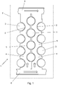
- the figures show an energy storage system 1 comprising a housing 2 in which a plurality of energy storage cells 3 are arranged.
- the energy storage cells 3 can be designed as round cells in a first embodiment and as pouch cells in a second embodiment. Alternatively, the energy storage cells 3 can also be designed in the form of prismatic cells.
- the energy storage system 1 described here stores electrical energy for the electrical drive and for ancillary units of an electric vehicle.
- a temperature control device 4 is arranged in the housing 2 , the temperature control device 4 making contact with the energy storage cells 3 at least in sections.
- the temperature control device 4 has a shape that is adapted in sections to the shape of the energy storage cells 3 .
- the energy storage cells 3 are in the form of round cells and are placed in a housing 2 in an upright position.
- a temperature control device 4 comprising a plurality of flow channels 6 is also arranged in the housing 2 .
- the flow channels 6 are arranged between the energy storage cells 3 in such a way that the energy storage cells 3 are arranged in rows.
- the temperature control device 4 in the form of the flow channels 6 has contact sections 5 , the contact sections 5 nestling against the outer contour of the energy storage cells 3 .
- the flow channels 6 are connected to a collector 8 on the inflow side and on the outflow side. On the inflow side, the temperature control medium is conveyed in the direction of the flow channels 6 via the collector 8 and the temperature control medium is transported away from the flow channels 6 via the collector 8 arranged on the outflow side.
- the collectors 8, like the flow channels 6, are designed as blow molded parts.
- the collector 8 is operatively connected to the cooling circuit of the electrically driven vehicle.
- the temperature control device 4 with flow channels 6 and collector 8 consists of thermoplastic material.
- the matrix of the thermoplastic material is provided with thermally conductive particles in the form of metal or carbon powder.
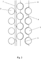
- FIG 2 shows an alternative embodiment of the in figure 1 described energy storage system 1.
- the temperature control device 4 includes a flow channel 6, which is designed in a meandering shape and runs in an arc between the energy storage cells 3.
- FIG 3 shows a method for producing the energy storage system 1 provided with the temperature control device 4 .
- the energy storage cells 3 are initially arranged in the housing 2 .
- the energy storage cells 3 are in the form of round cells, which are arranged in the housing 2 in an upright position.
- preforms 7 are arranged between the energy storage cells 3, the preforms 7 being arranged such that the energy storage cells 3 are arranged in rows between the preforms 7.
- the preforms 7 are elongated hollow bodies.
- a functional element for example a temperature and/or flow sensor, can be arranged in at least one preform 7 .
- the temperature control device 4 is formed from the preforms 7 by means of blow molding.
- the preforms 7 expand and thus come into contact with the energy storage cells 3.
- the preforms 7, or the temperature control device 4 with flow channels 6 produced from the preforms 7, nestle against the circumference of the energy storage cells 3.
- Contact sections 5 are formed from the flow channels 6 and are formed congruently with the circumference of the energy storage cells 3 . This results in a large-area contact between temperature control device 4 and energy storage cells 3.
- the functional element is positioned in the correct position in temperature control device 4. Furthermore, a functional element can be molded directly from preform 7 during blow molding.
- the flow channels 6 are then connected to the collectors 8 . In the present case, this takes place in a cohesive manner by means of a welded connection.
- the energy storage system 1 with the preform 7 arranged between the energy storage cells 3 can be seen in the left-hand section of the illustration.
- the temperature control device 4 formed from the preform 7 can be seen, which is arranged between the energy storage cells 3 and is adapted to the shape of the energy storage cells 3 .
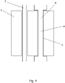
- FIG. 1 shows an alternative method for producing an energy storage system 1 according to FIG figure 3 .
- the energy storage cells 3 are in the form of prismatic cells.
- preforms 7 are arranged between energy storage cells 3 and the temperature control device 4 is formed from the preforms 7 by means of blow molding. During this process, the preforms 7 nestle against the outer contour of the energy storage cells 3 present as prismatic cells, resulting in a large-area contact between the temperature control device 4 and the energy storage cells 3 .
- a comparable configuration results when using energy storage cells 3 in the form of pouch cells.
Landscapes
- Engineering & Computer Science (AREA)
- Manufacturing & Machinery (AREA)
- Chemical & Material Sciences (AREA)
- Chemical Kinetics & Catalysis (AREA)
- Electrochemistry (AREA)
- General Chemical & Material Sciences (AREA)
- Blow-Moulding Or Thermoforming Of Plastics Or The Like (AREA)
Abstract
Description
- Die Erfindung betrifft ein Energiespeichersystem, umfassend ein Gehäuse, in welchem mehrere Energiespeicherzellen angeordnet sind, wobei in dem Gehäuse eine Temperiereinrichtung angeordnet ist, wobei die Temperiereinrichtung die Energiespeicherzellen zumindest abschnittsweise kontaktiert, wobei die Temperiereinrichtung eine zumindest abschnittsweise an die Form der Energiespeicherzellen angepasste Gestalt aufweist. Die Erfindung betrifft auch ein Fahrzeug mit einem derartigen Energiespeichersystem.
- Ein derartiges Energiespeichersystem ist beispielsweise aus der
WO 2019/046871 A1 bekannt. Derartige Energiespeichersysteme eignen sich insbesondere für stationäre Systeme und für den Einsatz in mobilen Systemen, beispielsweise in Fahrzeugen mit rein elektrischem oder ergänzend elektrifiziertem Antrieb. Ein für die Elektromobilität häufig eingesetztes Energiespeichersystem umfasst wiederaufladbare Energiespeicherzellen in Form von Akkumulatoren, wobei Lithium-Ionen-Akkumulatoren besonders häufig eingesetzt werden. Derartige Akkumulatoren setzen sich aus mehreren Energiespeicherzellen zusammen, welche gemeinsam in einem Gehäuse verbaut sind. Dabei bildet das Gehäuse, welches mehrere Energiespeicherzellen aufnimmt, ein Energiespeichermodul. - Elektrochemische Akkumulatoren, wie beispielsweise Lithium-Ionen-Akkumulatoren, weisen die höchstmögliche Kapazität nur in einem kleinen Temperaturspektrum auf. Daher ist es je nach Umgebungsbedingungen erforderlich, die in dem Gehäuse angeordneten Energiespeicherzellen zu kühlen oder zu erwärmen. Hierzu ist es aus dem oben genannten Stand der Technik bekannt, in dem Gehäuse eine Temperiereinrichtung mit Schläuchen anzuordnen, wobei die Schläuche zwischen den Energiespeicherzellen plaziert sind. Dabei sind die Schläuche flexibel und schmiegen sich an die Energiespeicherzellen an, wenn ein unter Druck stehendes Temperiermedium durch die Temperiereinrichtung gefördert wird. Hierbei ist aber problematisch, dass durch die schlauchartige Temperiereinrichtung eine mechanische Kraft auf die Energiespeicherzellen ausgeübt werden kann, insbesondere, wenn ein unter Druck stehendes Temperiermedium durch die Temperiereinrichtung gefördert wird. Mechanische Kräfte können auch aus Bremsvorgängen oder Kurvenfahrten resultieren und Schäden an dem Energiespeichersystem hervorrufen. Des Weiteren ist problematisch, dass sich in Abhängigkeit der Druckverhältnisse im Inneren der Temperiereinrichtung die Kontaktfläche zwischen Temperiereinrichtung und Energiespeicherzellen verringern kann, was zu lokalen Überhitzungen und Beschädigungen führen kann.
- Der Erfindung liegt die Aufgabe zugrunde, eine Temperiereinrichtung für ein Energiespeichersystem bereitzustellen, welches bei einfacher Montierbarkeit eine hohe Wärmeübertragung bei gleichzeitig guten mechanischen Eigenschaften ermöglicht.
- Diese Aufgabe wird mit den Merkmalen von Anspruch 1 gelöst. Auf vorteilhafte Ausgestaltungen nehmen die Unteransprüche Bezug.
- Das erfindungsgemäße Energiespeichersystem umfasst ein Gehäuse, in welchem mehrere Energiespeicherzellen angeordnet sind, wobei in dem Gehäuse eine Temperiereinrichtung angeordnet ist, wobei die Temperiereinrichtung die Energiespeicherzellen zumindest abschnittsweise kontaktiert, wobei die Temperiereinrichtung eine zumindest abschnittsweise an die Form der Energiespeicherzellen angepasste Gestalt aufweist, wobei die Temperiereinrichtung als Blasformteil ausgebildet ist. Dementsprechend ist die Temperiereinrichtung aus einem formstabilen Kunststoff, vorzugsweise einem formstabilen thermoplastischen Kunststoff, ausgebildet.
- Die Formgebung der Temperiereinrichtung erfolgt an Ort und Stelle innerhalb des Gehäuses und zwischen den Energiespeicherzellen. Zur Herstellung der Temperiereinrichtung wird zwischen den Energiespeicherzellen ein Vorformling angeordnet und mittels Blasformen in Form gebracht. Dabei schmiegt sich der Vorformling an die Energiespeicherzellen an, so dass eine besonders große Kontaktfläche zwischen Energiespeicherzellen und Temperiereinrichtung entsteht. Daraus wiederum resultiert ein besonders guter Wärmeübergang. Nach Abschluss des Blasformvorgangs ist die Temperiereinrichtung formstabil, wodurch insbesondere im Betrieb des Energiespeichersystems keine mechanischen Lasten auf die Energiespeicherzellen übertragen werden.
- Dadurch, dass die Temperiereinrichtung formstabil ist, kann diese aber auch als Stützeinrichtung fungieren und die Energiespeicherzellen an Ort und Stelle fixieren. Des Weiteren ergibt sich dadurch, dass die Temperiereinrichtung als Blasformteil ausgebildet ist, eine große Flexibilität hinsichtlich der Anordnung und der Ausgestaltung der Energiespeicherzellen. Insbesondere ist es nicht erforderlich, je nach Anordnung der Energiespeicherzellen und Ausgestaltung der Energiespeicherzellen die Gestalt der Temperiereinrichtung zu ändern. Die Formgebung der Temperiereinrichtung erfolgt selbsttätig während des Blasformvorgangs, so dass eine große Formenvielfalt für die Temperiereinrichtung realisierbar ist.
- Die Energiespeicherzellen können als Rundzellen ausgebildet sein. Derartige Energiespeicherzellen sind zylindrisch ausgebildet und werden aufrecht stehend oder liegend in dem Gehäuse angeordnet. Die Temperiereinrichtung schmiegt sich dabei an den Umfang der zylindrisch ausgebildeten Rundzellen an. Durch die im Zuge des Blasformens ausgeformte Temperiereinrichtung ist dabei ein großflächiger Kontakt der Temperiereinrichtung an die zylindrische Wand der Rundzellen gegeben. Dabei ist der Durchmesser und auch die Höhe der Rundzellen unerheblich, da die Formgebung der Temperiereinrichtung in Abhängigkeit der Gestalt der Energiespeicherzellen selbsttätig erfolgt. In alternativen Ausgestaltungen können die Energiespeicherzellen beispielsweise auch als Pouch-Zellen oder als prismatische Zellen ausgebildet sein.
- Die Temperiereinrichtung kann zumindest einen Strömungskanal aufweisen. Dazu ist die Temperiereinrichtung als Hohlkörper mit einem Strömungskanal ausgebildet. Durch den Strömungskanal kann Temperiermedium durch die Temperiereinrichtung strömen und dabei von den Energiespeicherzellen emittierte Wärme aufnehmen oder Wärme an die Energiespeicherzellen abgeben. In vorteilhaften Ausgestaltungen ist auch denkbar, dass ein Strömungskanal in mehrere Teilkanäle aufgeteilt ist, welche beispielsweise durch eine Membran oder eine Wand voneinander getrennt sind.
- Die Temperiereinrichtung kann Kontaktabschnitte aufweisen, wobei sich die Kontaktabschnitte an die Außenkontur der Energiespeicherzellen anschmiegen. Dadurch ergibt sich ein besonders großflächiger Kontakt zwischen Temperiereinrichtung und Energiespeicherzellen.
- Die Temperiereinrichtung kann mehrere Strömungskanäle aufweisen. Bei dieser Ausgestaltung werden zwischen den Energiespeichern mehrere separat voneinander ausgebildete Vorformlinge angeordnet, wobei jeder Vorformling jeweils einen Strömungskanal bildet. Dadurch weisen die Strömungskanäle eine einfache Gestalt auf und die Vorformlinge sind einfach montierbar. Des Weiteren ist denkbar, dass durch die Strömungskanäle ein an den Wärme- oder Kältebedarf angepasstes Temperiermedium strömt. In diesem Zusammenhang ist beispielsweise denkbar, dass in einem lokal begrenzten Störfall die angrenzenden Strömungskanäle mit einem hohen Volumenstrom durchströmenden Temperiermediums oder mit einem kälteren Temperiermedium beaufschlagt werden.
- Die Strömungskanäle können einströmseitig und/oder ausströmseitig mit einem Sammler verbunden sein. Dadurch können alle oder zumindest ein Teil der Strömungskanäle einfach mit Temperiermedium versorgt werden. Zwischen Sammler und Strömungskanälen können dabei zur Steuerung des Volumenstroms des die Strömungskanäle durchströmenden Temperiermediums schaltbare Ventile angeordnet sein. Ebenso wie die Strömungskanäle können auch die Sammler als Blasformteile ausgebildet sein.
- Das Energiespeichersystem kann Bestandteil eines Fahrzeugs sein. Dabei stellt das Energiespeichersystem elektrische Energie für einen elektrischen Antrieb bereit. Die erfindungsgemäße Ausgestaltung der Temperiereinrichtung in Form eines Blasformteils ist in diesem Zusammenhang besonders vorteilhaft, weil die Temperiereinrichtung an die Gestalt der Energiespeicherzellen angepasst ist. Dadurch ist zum einen ein flächiger und leistungsfähiger Wärmeübergang zwischen Temperiereinrichtung und Energiespeicherzellen gegeben und zum anderen kann die Temperiereinrichtung auf die Energiespeicherzellen während des Fahrbetriebs einwirkende Kräfte, insbesondere beim Bremsen und bei Kurvenfahrten, abfangen.
- Der Sammler kann mit dem Kühlkreislauf eines Fahrzeugs in Wirkverbindung stehen. Bei dieser Ausgestaltung ist die Temperiereinrichtung des Energiespeichersystems an den leistungsfähigen Kühlkreislauf des Fahrzeugs angebunden. Dabei kann der Sammler direkt oder indirekt mit dem Kühlkreislauf verbunden sein.
- Die Temperiereinrichtung kann mäanderförmig ausgebildet sein. Dabei umgibt die Temperiereinrichtung bogenförmig mehrere Energiespeicherzellen, die regelmäßig angeordnet sein können und durch die Temperiereinrichtung in mehrere Reihen getrennt werden.
- Die Temperiereinrichtung kann aus thermoplastischem Kunststoff ausgebildet sein. Thermoplastische Kunststoffe sind einfach mittels Blasformen verarbeitbar. Zur Verbesserung der Wärmeleitfähigkeit kann der thermoplastische Kunststoff mit Additiven versehen sein. Mögliche Additive sind beispielsweise metallische oder kohlenstoffhaltige Partikel. Des Weiteren kann die Matrix des thermoplastischen Kunststoffs zur Verbesserung der mechanischen Eigenschaften mit einer Faserverstärkung versehen sein.
- Ein erfindungsgemäßes Fahrzeug umfasst einen zumindest unterstützenden elektrischen Antrieb und ein Energiespeichersystem mit einer Temperiereinrichtung wie zuvor beschrieben.
- Die Aufgabe der Erfindung wird auch gelöst durch ein Verfahren zur Herstellung einer Temperiereinrichtung für einen Energiespeicher, umfassend eine Anordnung von Energiespeicherzellen, bei welchem ein Vorformling in der Anordnung von Energiespeicherzellen angeordnet wird und die Temperiereinrichtung mittels Blasformen aus dem Vorformling ausgebildet wird. Dementsprechend werden bei dem erfindungsgemäßen Verfahren zunächst die Energiespeicherzellen in dem Gehäuse angeordnet und gegebenenfalls in dem Gehäuse befestigt. Anschließend wird der Vorformling zwischen den Energiespeicherzellen angeordnet, wobei die Anordnung des Vorformlings mäanderförmig erfolgen kann. Alternativ können mehrere Vorformlinge zwischen den Energiespeicherzellen angeordnet werden. Anschließend erfolgt die Formgebung der Temperiereinrichtung mittels Blasformen. Dabei wird das Material des Vorformlings erwärmt und unter Druck gesetzt, wodurch sich der Vorformling plastisch verformt und schmiegt sich teilweise an die Energiespeicherzellen an. Daraus resultiert eine große Kontaktfläche zwischen Temperiereinrichtung und Energiespeicherzellen. Nach Abschluss des Blasformverfahrens ist die Temperiereinrichtung formstabil und kann neben der Temperierfunktion gleichzeitig eine Abstützung für die Energiespeicherzellen bilden.
- Während des Blasformens kann zumindest ein Funktionselement in die Temperiereinrichtung eingeformt oder angeordnet werden. Strömungskanäle von Temperierkreisläufen können mehrere für die Funktionsfähigkeit der Temperiereinrichtung erforderliche Funktionselemente enthalten. Dies sind beispielsweise Drosselventile, Rückschlagventile, schaltbare Ventile, Pumpen, Durchflusssensoren und/oder Temperatursensoren. Bei dem erfindungsgemäßen Energiespeichersystem kann zumindest eines der zuvor beschriebenen Funktionselemente in der Temperiereinrichtung, beispielsweise innerhalb eines Strömungskanals, angeordnet sein, so dass das Funktionselement mit dem Temperiermedium in Kontakt steht.
- Durch die Anordnung des Funktionselementes innerhalb des Energiespeichersystems, zwischen den Energiespeicherzellen, können Zustandsparameter des Temperiermediums direkt in den zu temperierenden Bereichen erfasst und auch beeinflusst werden. Dabei kann das Funktionselement gemäß einer ersten Ausgestaltung direkt aus dem Grundkörper ausgeformt sein, was insbesondere für passive Elemente wie Drosselventile in Betracht kommt. Alternativ können Funktionselemente in dem Vorformling so angeordnet werden, dass diese nach dem Blasformen positionsrichtig in der Temperiereinrichtung angeordnet sind.
- Einige der Ausgestaltungen des erfindungsgemäßen Energiespeichersystems werden nachfolgend anhand der Figuren näher erläutert. Diese zeigen, jeweils schematisch:
- Fig. 1
- ein Energiespeichersystem mit mehreren Strömungskanälen;
- Fig. 2
- ein Energiespeichersystem mit einer mäanderförmigen Temperiereinrichtung;
- Fig. 3
- die Herstellung eines Energiespeichersystems gemäß
Fig. 1 ; - Fig. 4
- die Herstellung eines Energiespeichersystems mit Energiespeicherzellen in Form von prismatischen Zellen.
- Die Figuren zeigen ein Energiespeichersystem 1, umfassend ein Gehäuse 2, in welchem mehrere Energiespeicherzellen 3 angeordnet sind. Dabei können die Energiespeicherzellen 3 in einer ersten Ausgestaltung als Rundzellen und in einer zweiten Ausgestaltung als Pouch-Zellen ausgebildet sein. Alternativ können die Energiespeicherzellen 3 aber auch in Form von prismatischen Zellen ausgebildet sein. Das hier beschriebene Energiespeichersystem 1 speichert elektrische Energie für den elektrischen Antrieb und von Nebenaggregaten eines Elektrofahrzeugs.
- In dem Gehäuse 2 ist eine Temperiereinrichtung 4 angeordnet, wobei die Temperiereinrichtung 4 die Energiespeicherzellen 3 zumindest abschnittsweise kontaktiert. Dabei weist die Temperiereinrichtung 4 eine abschnittsweise an die Form der Energiespeicherzellen 3 angepasste Gestalt auf.
- Bei der Ausgestaltung gemäß
Figur 1 sind die Energiespeicherzellen 3 in Form von Rundzellen ausgebildet und aufrecht stehend in einem Gehäuse 2 plaziert. In dem Gehäuse 2 ist ferner eine Temperiereinrichtung 4 umfassend mehrere Strömungskanäle 6 angeordnet. Dabei sind die Strömungskanäle 6 so zwischen den Energiespeicherzellen 3 angeordnet, dass die Energiespeicherzellen 3 in Reihen angeordnet sind. Die Temperiereinrichtung 4 in Form der Strömungskanäle 6 weist Kontaktabschnitte 5 auf, wobei sich die Kontaktabschnitte 5 an die Außenkontur der Energiespeicherzellen 3 anschmiegen. - Die Strömungskanäle 6 sind einströmseitig und ausströmseitig mit einem Sammler 8 verbunden. Einströmseitig wird über den Sammler 8 Temperiermedium in Richtung der Strömungskanäle 6 gefördert und über den ausströmseitig angeordneten Sammler 8 wird das Temperiermedium aus den Strömungskanälen 6 wegtransportiert. Die Sammler 8 sind, ebenso wie die Strömungskanäle 6, als Blasformteil ausgebildet. Der Sammler 8 steht mit dem Kühlkreislauf des elektrisch angetriebenen Fahrzeugs in Wirkverbindung.
- Die Temperiereinrichtung 4 mit Strömungskanälen 6 und Sammler 8 besteht aus thermoplastischem Werkstoff. Zur Verbesserung der Wärmeleitfähigkeit ist die Matrix des thermoplastischen Werkstoffs mit wärmeleitenden Partikeln in Form von Metall- oder Kohlenstoffpulver versehen.
-
Figur 2 zeigt eine alternative Ausgestaltung des inFigur 1 beschriebenen Energiespeichersystems 1. Bei der vorliegenden Ausgestaltung umfasst die Temperiereinrichtung 4 einen Strömungskanal 6, welcher mäanderförmig ausgebildet ist und bogenförmig zwischen den Energiespeicherzellen 3 verläuft. -
Figur 3 zeigt ein Verfahren zur Herstellung des mit der Temperiereinrichtung 4 versehenen Energiespeichersystems 1. Dabei werden zunächst die Energiespeicherzellen 3 in dem Gehäuse 2 angeordnet. Bei der vorliegenden Ausgestaltung liegen die Energiespeicherzellen 3 in Form von Rundzellen vor, welche aufrecht stehend in dem Gehäuse 2 angeordnet werden. - In einem zweiten Schritt werden Vorformlinge 7 zwischen den Energiespeicherzellen 3 angeordnet, wobei die Anordnung der Vorformlinge 7 so erfolgt, dass die Energiespeicherzellen 3 zwischen den Vorformlingen 7 in Reihen angeordnet sind. Die Vorformlinge 7 sind länglich ausgebildete Hohlkörper. In zumindest einem Vorformling 7 kann ein Funktionselement, beispielsweise ein Temperatur- und/oder Durchflusssensor, angeordnet werden.
- Im nächsten Schritt wird aus den Vorformlingen 7 mittels Blasformen die Temperiereinrichtung 4 ausgebildet. Durch die während des Blasformens erfolgende plastische Verformung der Vorformlinge 7 dehnen sich die Vorformlinge 7 aus und gelangen dadurch in Kontakt mit den Energiespeicherzellen 3. Dabei schmiegen sich die Vorformlinge 7, beziehungsweise die aus den Vorformlingen 7 entstehende Temperiereinrichtung 4 mit Strömungskanälen 6, an den Umfang der Energiespeicherzellen 3 an. Aus den Strömungskanälen 6 bilden sich Kontaktabschnitte 5 aus, welche kongruent zu dem Umfang der Energiespeicherzellen 3 ausgebildet sind. Dadurch ergibt sich ein großflächiger Kontakt zwischen Temperiereinrichtung 4 und Energiespeicherzellen 3. Während des Blasformens positioniert sich das Funktionselement lagerichtig in der Temperiereinrichtung 4. Des Weiteren kann ein Funktionselement während des Blasformens direkt aus dem Vorformling 7 ausgeformt werden.
- Die Strömungskanäle 6 werden anschließend mit den Sammlern 8 verbunden. Dies erfolgt vorliegend stoffschlüssig mittels einer Schweißverbindung.
- Im linken Abschnitt der Darstellung ist das Energiespeichersystem 1 mit zwischen den Energiespeicherzellen 3 angeordnetem Vorformling 7 zu erkennen. In der rechten Darstellung ist die aus dem Vorformling 7 ausgeformte Temperiereinrichtung 4 zu erkennen, welche zwischen den Energiespeicherzellen 3 angeordnet und an die Form der Energiespeicherzellen 3 angepasst ist.
-
Figur 4 zeigt ein alternatives Verfahren zur Herstellung eines Energiespeichersystems 1 gemäßFigur 3 . Bei der vorliegenden Ausgestaltung sind die Energiespeicherzellen 3 in Form von prismatischen Zellen ausgebildet. Auch bei dieser Ausgestaltung werden Vorformlinge 7 zwischen Energiespeicherzellen 3 angeordnet und die Temperiereinrichtung 4 mittels Blasformen aus den Vorformlingen 7 ausgebildet. Bei diesem Vorgang schmiegen sich die Vorformlinge 7 an die Außenkontur der als prismatischen Zellen vorliegenden Energiespeicherzellen 3 an, woraus ein großflächiger Kontakt zwischen Temperiereinrichtung 4 und Energiespeicherzellen 3 resultiert. Eine vergleichbare Ausgestaltung ergibt sich bei Verwendung von Energiespeicherzellen 3 in Form von Pouch-Zellen.
Claims (14)
- Energiespeichersystem (1), umfassend ein Gehäuse (2) in welchem mehrere Energiespeicherzellen (3) angeordnet sind, wobei in dem Gehäuse (2) eine Temperiereinrichtung (4) angeordnet ist, wobei die Temperiereinrichtung (4) die Energiespeicherzellen (3) zumindest abschnittsweise kontaktiert, wobei die Temperiereinrichtung (4) eine zumindest abschnittsweise an die Form der Energiespeicherzellen (3) angepasste Gestalt aufweist, dadurch gekennzeichnet, dass die Temperiereinrichtung (4) als Blasformteil ausgebildet ist.
- Energiespeichersystem nach Anspruch 1, dadurch gekennzeichnet, dass die Energiespeicherzellen (3) als Rundzellen ausgebildet sind.
- Energiespeichersystem nach Anspruch 1, dadurch gekennzeichnet, dass die Energiespeicherzellen (3) als prismatische Zellen oder als Pouch-Zellen ausgebildet sind.
- Energiespeichersystem nach einem der Ansprüche 1 bis 3, dadurch gekennzeichnet, dass die Temperiereinrichtung (4) zumindest einen Strömungskanal (6) aufweist.
- Energiespeichersystem nach einem der Ansprüche 1 bis 4, dadurch gekennzeichnet, dass die Temperiereinrichtung (4) Kontaktabschnitte (5) aufweist, welche sich an die Außenkontur der Energiespeicherzellen (3) anschmiegen.
- Energiespeichersystem nach einem der Ansprüche 1 bis 5, dadurch gekennzeichnet, dass die Temperiereinrichtung (4) mehrere Strömungskanäle (6) aufweist
- Energiespeichersystem nach Anspruch 6, dadurch gekennzeichnet, dass die Strömungskanäle (6) einströmseitig und ausströmseitig mit einem Sammler (8) verbunden sind.
- Energiespeichersystem nach einem der Ansprüche 1 bis 7, dadurch gekennzeichnet, dass das Energiespeichersystem (1) Bestandteil eines Fahrzeugs ist.
- Energiespeichersystem nach Anspruch 7 oder 8, dadurch gekennzeichnet, dass der Sammler (8) mit dem Kühlkreislauf eines Fahrzeugs in Wirkverbindung steht.
- Energiespeichersystem nach einem der Ansprüche 1 bis 9, dadurch gekennzeichnet, dass die Temperiereinrichtung (4) mäanderförmig ausgebildet ist.
- Energiespeichersystem nach einem der Ansprüche 1 bis 10, dadurch gekennzeichnet, dass die Temperiereinrichtung (4) aus thermoplastischem Kunststoff ausgebildet ist.
- Fahrzeug, umfassend einen zumindest unterstützenden elektrischen Antrieb und ein Energiespeichersystem (1) nach einem der vorherigen Ansprüche.
- Verfahren zur Herstellung eines Energiespeichersystems (1), umfassend ein Gehäuse (2), in welchem mehrere Energiespeicherzellen (3) angeordnet sind, bei welchem Energiespeicherzellen (3) in einem Gehäuse (2) angeordnet werden, anschließend ein Vorformling (7) zwischen den Energiespeicherzellen (3) angeordnet wird und die Temperiereinrichtung (4) mittels Blasformen aus dem Vorformling (7) ausgebildet wird.
- Verfahren nach Anspruch 13, dadurch gekennzeichnet, dass während des Blasformens ein Funktionselement in die Temperiereinrichtung (4) eingeformt oder angeordnet wird.
Priority Applications (7)
| Application Number | Priority Date | Filing Date | Title |
|---|---|---|---|
| EP20199326.8A EP3979393B1 (de) | 2020-09-30 | 2020-09-30 | Energiespeichersystem mit temperiereinrichtung |
| KR1020217041288A KR20230079299A (ko) | 2020-09-30 | 2021-09-29 | 온도 제어 유닛을 갖는 에너지 저장 시스템 |
| JP2021560748A JP7353386B2 (ja) | 2020-09-30 | 2021-09-29 | 温度制御ユニットを有するエネルギー貯蔵システム |
| PCT/IB2021/058966 WO2022070114A1 (en) | 2020-09-30 | 2021-09-29 | Energy storage system with temperature control unit |
| CN202180003409.7A CN114788070A (zh) | 2020-09-30 | 2021-09-29 | 具有温度控制单元的储能系统 |
| MX2021012703A MX2021012703A (es) | 2020-09-30 | 2021-09-29 | Sistema de almacenamiento de energia con unidad de control de temperatura. |
| US17/553,203 US20220109202A1 (en) | 2020-09-30 | 2021-12-16 | Energy storage system with temperature control unit |
Applications Claiming Priority (1)
| Application Number | Priority Date | Filing Date | Title |
|---|---|---|---|
| EP20199326.8A EP3979393B1 (de) | 2020-09-30 | 2020-09-30 | Energiespeichersystem mit temperiereinrichtung |
Publications (2)
| Publication Number | Publication Date |
|---|---|
| EP3979393A1 true EP3979393A1 (de) | 2022-04-06 |
| EP3979393B1 EP3979393B1 (de) | 2022-12-21 |
Family
ID=72709142
Family Applications (1)
| Application Number | Title | Priority Date | Filing Date |
|---|---|---|---|
| EP20199326.8A Active EP3979393B1 (de) | 2020-09-30 | 2020-09-30 | Energiespeichersystem mit temperiereinrichtung |
Country Status (2)
| Country | Link |
|---|---|
| EP (1) | EP3979393B1 (de) |
| WO (1) | WO2022070114A1 (de) |
Citations (4)
| Publication number | Priority date | Publication date | Assignee | Title |
|---|---|---|---|---|
| FR2782399A1 (fr) * | 1998-08-13 | 2000-02-18 | Plastiques De France Ind | Dispositif et procede de regulation thermique, par exemple pour le refroidissement de batteries d'accumulateurs de vehicules electriques |
| US20080311468A1 (en) * | 2007-06-18 | 2008-12-18 | Weston Arthur Hermann | Optimized cooling tube geometry for intimate thermal contact with cells |
| DE102015221272A1 (de) * | 2015-10-30 | 2017-05-04 | Bayerische Motoren Werke Aktiengesellschaft | Temperiereinheit und Batteriemodul mit einer solchen |
| WO2019046871A1 (de) | 2017-09-05 | 2019-03-14 | Miba Aktiengesellschaft | Akkumulator |
-
2020
- 2020-09-30 EP EP20199326.8A patent/EP3979393B1/de active Active
-
2021
- 2021-09-29 WO PCT/IB2021/058966 patent/WO2022070114A1/en not_active Ceased
Patent Citations (4)
| Publication number | Priority date | Publication date | Assignee | Title |
|---|---|---|---|---|
| FR2782399A1 (fr) * | 1998-08-13 | 2000-02-18 | Plastiques De France Ind | Dispositif et procede de regulation thermique, par exemple pour le refroidissement de batteries d'accumulateurs de vehicules electriques |
| US20080311468A1 (en) * | 2007-06-18 | 2008-12-18 | Weston Arthur Hermann | Optimized cooling tube geometry for intimate thermal contact with cells |
| DE102015221272A1 (de) * | 2015-10-30 | 2017-05-04 | Bayerische Motoren Werke Aktiengesellschaft | Temperiereinheit und Batteriemodul mit einer solchen |
| WO2019046871A1 (de) | 2017-09-05 | 2019-03-14 | Miba Aktiengesellschaft | Akkumulator |
Also Published As
| Publication number | Publication date |
|---|---|
| WO2022070114A1 (en) | 2022-04-07 |
| EP3979393B1 (de) | 2022-12-21 |
Similar Documents
| Publication | Publication Date | Title |
|---|---|---|
| DE102008059955B4 (de) | Verfahren zur Herstellung einer Kühlplatte mit einem integrierten Kühlkanal für eine Batterie und Verwendung einer Kühlplatte | |
| EP3295509B1 (de) | Energiespeicher eines kraftfahrzeugs | |
| DE102008059969B4 (de) | Vorrichtung zur Kühlung einer Batterie und Verwendung der Vorrichtung | |
| EP3919299B1 (de) | Rohranordnung für den transport von temperiermedium | |
| DE102008034695B4 (de) | Batterie, insbesondere Fahrzeugbatterie | |
| EP2950366B1 (de) | Batterieeinheit mit einer mehrzahl von batteriezellen sowie batteriemodul mit einer mehrzahl solcher batterieeinheiten | |
| DE102018219461A1 (de) | Batteriemodulanordnung für ein Kraftfahrzeug und Kraftfahrzeug | |
| DE102018117482A1 (de) | Verfahren zur herstellung einer rohranordnung | |
| EP4067048B1 (de) | Verfahren zur herstellung einer anordnung für den transport von medien und anordnung | |
| EP3979393B1 (de) | Energiespeichersystem mit temperiereinrichtung | |
| EP3919262A1 (de) | Verfahren zur herstellung einer rohranordnung für den transport von temperiermedium | |
| DE102019130801A1 (de) | Speichereinrichtung zum Speichern von elektrischer Energie für ein Kraftfahrzeug sowie Kraftfahrzeug | |
| WO2023280522A1 (de) | Verfahren zum herstellen eines konditionierelements, konditionierelement sowie elektrischer energiespeicher | |
| DE102013105401B4 (de) | Bearbeitungswerkzeug zum thermischen Bearbeiten von Bauteilen | |
| DE102008034878A1 (de) | Batterie mit einer Wärmeleitplatte zum Temperieren der Batterie | |
| EP1777062B1 (de) | Verfahren und Vorrichtung zum Verschweissen von Kunststoffhohlkörpern | |
| EP4631126A1 (de) | Energiespeichervorrichtung für ein kraftfahrzeug | |
| EP3347193B1 (de) | Verfahren zum herstellen eines fmv-hybridbauteils und fmv-hybridbauteil | |
| DE102018123972A1 (de) | Kühlplatte und Verfahren zur Herstellung einer Kühlplatte | |
| DE102019133417A1 (de) | Elektrischer Energiespeicher für ein Kraftfahrzeug sowie Verfahren zum Herstellen eines solchen Energiespeichers | |
| EP4067667A1 (de) | Anordnung für den transport von medien und verfahren zu deren herstellung | |
| DE102021005260A1 (de) | Kühleinrichtung für einen elektrischen Energiespeicher eines Kraftfahrzeugs, insbesondere eines Kraftwagens | |
| DE102016118751A1 (de) | Energiespeichersystem, energiespeichermodul und -anordnung sowie verfahren zum zusammenbau eines energiespeichermoduls | |
| DE102021111737B4 (de) | Batteriezelle | |
| DE102020124738A1 (de) | Verfahren und Stützvorrichtung zum Stützen eines Batteriegehäuses beim Einsetzen eines Batteriemoduls |
Legal Events
| Date | Code | Title | Description |
|---|---|---|---|
| PUAI | Public reference made under article 153(3) epc to a published international application that has entered the european phase |
Free format text: ORIGINAL CODE: 0009012 |
|
| STAA | Information on the status of an ep patent application or granted ep patent |
Free format text: STATUS: REQUEST FOR EXAMINATION WAS MADE |
|
| 17P | Request for examination filed |
Effective date: 20210630 |
|
| AK | Designated contracting states |
Kind code of ref document: A1 Designated state(s): AL AT BE BG CH CY CZ DE DK EE ES FI FR GB GR HR HU IE IS IT LI LT LU LV MC MK MT NL NO PL PT RO RS SE SI SK SM TR |
|
| GRAP | Despatch of communication of intention to grant a patent |
Free format text: ORIGINAL CODE: EPIDOSNIGR1 |
|
| STAA | Information on the status of an ep patent application or granted ep patent |
Free format text: STATUS: GRANT OF PATENT IS INTENDED |
|
| INTG | Intention to grant announced |
Effective date: 20220801 |
|
| GRAS | Grant fee paid |
Free format text: ORIGINAL CODE: EPIDOSNIGR3 |
|
| GRAA | (expected) grant |
Free format text: ORIGINAL CODE: 0009210 |
|
| STAA | Information on the status of an ep patent application or granted ep patent |
Free format text: STATUS: THE PATENT HAS BEEN GRANTED |
|
| AK | Designated contracting states |
Kind code of ref document: B1 Designated state(s): AL AT BE BG CH CY CZ DE DK EE ES FI FR GB GR HR HU IE IS IT LI LT LU LV MC MK MT NL NO PL PT RO RS SE SI SK SM TR |
|
| REG | Reference to a national code |
Ref country code: GB Ref legal event code: FG4D Free format text: NOT ENGLISH |
|
| REG | Reference to a national code |
Ref country code: DE Ref legal event code: R096 Ref document number: 502020002225 Country of ref document: DE |
|
| REG | Reference to a national code |
Ref country code: CH Ref legal event code: EP |
|
| REG | Reference to a national code |
Ref country code: AT Ref legal event code: REF Ref document number: 1539597 Country of ref document: AT Kind code of ref document: T Effective date: 20230115 |
|
| REG | Reference to a national code |
Ref country code: IE Ref legal event code: FG4D Free format text: LANGUAGE OF EP DOCUMENT: GERMAN |
|
| REG | Reference to a national code |
Ref country code: LT Ref legal event code: MG9D |
|
| REG | Reference to a national code |
Ref country code: NL Ref legal event code: MP Effective date: 20221221 |
|
| PG25 | Lapsed in a contracting state [announced via postgrant information from national office to epo] |
Ref country code: SE Free format text: LAPSE BECAUSE OF FAILURE TO SUBMIT A TRANSLATION OF THE DESCRIPTION OR TO PAY THE FEE WITHIN THE PRESCRIBED TIME-LIMIT Effective date: 20221221 Ref country code: NO Free format text: LAPSE BECAUSE OF FAILURE TO SUBMIT A TRANSLATION OF THE DESCRIPTION OR TO PAY THE FEE WITHIN THE PRESCRIBED TIME-LIMIT Effective date: 20230321 Ref country code: LT Free format text: LAPSE BECAUSE OF FAILURE TO SUBMIT A TRANSLATION OF THE DESCRIPTION OR TO PAY THE FEE WITHIN THE PRESCRIBED TIME-LIMIT Effective date: 20221221 Ref country code: FI Free format text: LAPSE BECAUSE OF FAILURE TO SUBMIT A TRANSLATION OF THE DESCRIPTION OR TO PAY THE FEE WITHIN THE PRESCRIBED TIME-LIMIT Effective date: 20221221 |
|
| PG25 | Lapsed in a contracting state [announced via postgrant information from national office to epo] |
Ref country code: RS Free format text: LAPSE BECAUSE OF FAILURE TO SUBMIT A TRANSLATION OF THE DESCRIPTION OR TO PAY THE FEE WITHIN THE PRESCRIBED TIME-LIMIT Effective date: 20221221 Ref country code: LV Free format text: LAPSE BECAUSE OF FAILURE TO SUBMIT A TRANSLATION OF THE DESCRIPTION OR TO PAY THE FEE WITHIN THE PRESCRIBED TIME-LIMIT Effective date: 20221221 Ref country code: HR Free format text: LAPSE BECAUSE OF FAILURE TO SUBMIT A TRANSLATION OF THE DESCRIPTION OR TO PAY THE FEE WITHIN THE PRESCRIBED TIME-LIMIT Effective date: 20221221 Ref country code: GR Free format text: LAPSE BECAUSE OF FAILURE TO SUBMIT A TRANSLATION OF THE DESCRIPTION OR TO PAY THE FEE WITHIN THE PRESCRIBED TIME-LIMIT Effective date: 20230322 |
|
| P01 | Opt-out of the competence of the unified patent court (upc) registered |
Effective date: 20230524 |
|
| PG25 | Lapsed in a contracting state [announced via postgrant information from national office to epo] |
Ref country code: NL Free format text: LAPSE BECAUSE OF FAILURE TO SUBMIT A TRANSLATION OF THE DESCRIPTION OR TO PAY THE FEE WITHIN THE PRESCRIBED TIME-LIMIT Effective date: 20221221 |
|
| PG25 | Lapsed in a contracting state [announced via postgrant information from national office to epo] |
Ref country code: SM Free format text: LAPSE BECAUSE OF FAILURE TO SUBMIT A TRANSLATION OF THE DESCRIPTION OR TO PAY THE FEE WITHIN THE PRESCRIBED TIME-LIMIT Effective date: 20221221 Ref country code: RO Free format text: LAPSE BECAUSE OF FAILURE TO SUBMIT A TRANSLATION OF THE DESCRIPTION OR TO PAY THE FEE WITHIN THE PRESCRIBED TIME-LIMIT Effective date: 20221221 Ref country code: PT Free format text: LAPSE BECAUSE OF FAILURE TO SUBMIT A TRANSLATION OF THE DESCRIPTION OR TO PAY THE FEE WITHIN THE PRESCRIBED TIME-LIMIT Effective date: 20230421 Ref country code: ES Free format text: LAPSE BECAUSE OF FAILURE TO SUBMIT A TRANSLATION OF THE DESCRIPTION OR TO PAY THE FEE WITHIN THE PRESCRIBED TIME-LIMIT Effective date: 20221221 Ref country code: EE Free format text: LAPSE BECAUSE OF FAILURE TO SUBMIT A TRANSLATION OF THE DESCRIPTION OR TO PAY THE FEE WITHIN THE PRESCRIBED TIME-LIMIT Effective date: 20221221 Ref country code: CZ Free format text: LAPSE BECAUSE OF FAILURE TO SUBMIT A TRANSLATION OF THE DESCRIPTION OR TO PAY THE FEE WITHIN THE PRESCRIBED TIME-LIMIT Effective date: 20221221 |
|
| PG25 | Lapsed in a contracting state [announced via postgrant information from national office to epo] |
Ref country code: SK Free format text: LAPSE BECAUSE OF FAILURE TO SUBMIT A TRANSLATION OF THE DESCRIPTION OR TO PAY THE FEE WITHIN THE PRESCRIBED TIME-LIMIT Effective date: 20221221 Ref country code: PL Free format text: LAPSE BECAUSE OF FAILURE TO SUBMIT A TRANSLATION OF THE DESCRIPTION OR TO PAY THE FEE WITHIN THE PRESCRIBED TIME-LIMIT Effective date: 20221221 Ref country code: IS Free format text: LAPSE BECAUSE OF FAILURE TO SUBMIT A TRANSLATION OF THE DESCRIPTION OR TO PAY THE FEE WITHIN THE PRESCRIBED TIME-LIMIT Effective date: 20230421 Ref country code: AL Free format text: LAPSE BECAUSE OF FAILURE TO SUBMIT A TRANSLATION OF THE DESCRIPTION OR TO PAY THE FEE WITHIN THE PRESCRIBED TIME-LIMIT Effective date: 20221221 |
|
| REG | Reference to a national code |
Ref country code: DE Ref legal event code: R097 Ref document number: 502020002225 Country of ref document: DE |
|
| PLBE | No opposition filed within time limit |
Free format text: ORIGINAL CODE: 0009261 |
|
| STAA | Information on the status of an ep patent application or granted ep patent |
Free format text: STATUS: NO OPPOSITION FILED WITHIN TIME LIMIT |
|
| PG25 | Lapsed in a contracting state [announced via postgrant information from national office to epo] |
Ref country code: DK Free format text: LAPSE BECAUSE OF FAILURE TO SUBMIT A TRANSLATION OF THE DESCRIPTION OR TO PAY THE FEE WITHIN THE PRESCRIBED TIME-LIMIT Effective date: 20221221 |
|
| 26N | No opposition filed |
Effective date: 20230922 |
|
| PG25 | Lapsed in a contracting state [announced via postgrant information from national office to epo] |
Ref country code: SI Free format text: LAPSE BECAUSE OF FAILURE TO SUBMIT A TRANSLATION OF THE DESCRIPTION OR TO PAY THE FEE WITHIN THE PRESCRIBED TIME-LIMIT Effective date: 20221221 |
|
| REG | Reference to a national code |
Ref country code: CH Ref legal event code: PL |
|
| PG25 | Lapsed in a contracting state [announced via postgrant information from national office to epo] |
Ref country code: LU Free format text: LAPSE BECAUSE OF NON-PAYMENT OF DUE FEES Effective date: 20230930 |
|
| REG | Reference to a national code |
Ref country code: BE Ref legal event code: MM Effective date: 20230930 |
|
| PG25 | Lapsed in a contracting state [announced via postgrant information from national office to epo] |
Ref country code: LU Free format text: LAPSE BECAUSE OF NON-PAYMENT OF DUE FEES Effective date: 20230930 Ref country code: IT Free format text: LAPSE BECAUSE OF FAILURE TO SUBMIT A TRANSLATION OF THE DESCRIPTION OR TO PAY THE FEE WITHIN THE PRESCRIBED TIME-LIMIT Effective date: 20221221 Ref country code: MC Free format text: LAPSE BECAUSE OF FAILURE TO SUBMIT A TRANSLATION OF THE DESCRIPTION OR TO PAY THE FEE WITHIN THE PRESCRIBED TIME-LIMIT Effective date: 20221221 |
|
| REG | Reference to a national code |
Ref country code: IE Ref legal event code: MM4A |
|
| PG25 | Lapsed in a contracting state [announced via postgrant information from national office to epo] |
Ref country code: IE Free format text: LAPSE BECAUSE OF NON-PAYMENT OF DUE FEES Effective date: 20230930 |
|
| PG25 | Lapsed in a contracting state [announced via postgrant information from national office to epo] |
Ref country code: CH Free format text: LAPSE BECAUSE OF NON-PAYMENT OF DUE FEES Effective date: 20230930 |
|
| PG25 | Lapsed in a contracting state [announced via postgrant information from national office to epo] |
Ref country code: IE Free format text: LAPSE BECAUSE OF NON-PAYMENT OF DUE FEES Effective date: 20230930 Ref country code: CH Free format text: LAPSE BECAUSE OF NON-PAYMENT OF DUE FEES Effective date: 20230930 |
|
| PG25 | Lapsed in a contracting state [announced via postgrant information from national office to epo] |
Ref country code: BE Free format text: LAPSE BECAUSE OF NON-PAYMENT OF DUE FEES Effective date: 20230930 |
|
| PGFP | Annual fee paid to national office [announced via postgrant information from national office to epo] |
Ref country code: DE Payment date: 20240919 Year of fee payment: 5 |
|
| PGFP | Annual fee paid to national office [announced via postgrant information from national office to epo] |
Ref country code: FR Payment date: 20240917 Year of fee payment: 5 |
|
| PG25 | Lapsed in a contracting state [announced via postgrant information from national office to epo] |
Ref country code: BG Free format text: LAPSE BECAUSE OF FAILURE TO SUBMIT A TRANSLATION OF THE DESCRIPTION OR TO PAY THE FEE WITHIN THE PRESCRIBED TIME-LIMIT Effective date: 20221221 |
|
| PG25 | Lapsed in a contracting state [announced via postgrant information from national office to epo] |
Ref country code: BG Free format text: LAPSE BECAUSE OF FAILURE TO SUBMIT A TRANSLATION OF THE DESCRIPTION OR TO PAY THE FEE WITHIN THE PRESCRIBED TIME-LIMIT Effective date: 20221221 |
|
| GBPC | Gb: european patent ceased through non-payment of renewal fee |
Effective date: 20240930 |
|
| PG25 | Lapsed in a contracting state [announced via postgrant information from national office to epo] |
Ref country code: GB Free format text: LAPSE BECAUSE OF NON-PAYMENT OF DUE FEES Effective date: 20240930 |
|
| PG25 | Lapsed in a contracting state [announced via postgrant information from national office to epo] |
Ref country code: CY Free format text: LAPSE BECAUSE OF FAILURE TO SUBMIT A TRANSLATION OF THE DESCRIPTION OR TO PAY THE FEE WITHIN THE PRESCRIBED TIME-LIMIT; INVALID AB INITIO Effective date: 20200930 |
|
| PG25 | Lapsed in a contracting state [announced via postgrant information from national office to epo] |
Ref country code: HU Free format text: LAPSE BECAUSE OF FAILURE TO SUBMIT A TRANSLATION OF THE DESCRIPTION OR TO PAY THE FEE WITHIN THE PRESCRIBED TIME-LIMIT; INVALID AB INITIO Effective date: 20200930 |
|
| PGFP | Annual fee paid to national office [announced via postgrant information from national office to epo] |
Ref country code: AT Payment date: 20251020 Year of fee payment: 5 |
|
| PG25 | Lapsed in a contracting state [announced via postgrant information from national office to epo] |
Ref country code: TR Free format text: LAPSE BECAUSE OF FAILURE TO SUBMIT A TRANSLATION OF THE DESCRIPTION OR TO PAY THE FEE WITHIN THE PRESCRIBED TIME-LIMIT Effective date: 20221221 |