EP3979015A1 - Machine tool, tool load display method for machine tool, and program for machine tool - Google Patents
Machine tool, tool load display method for machine tool, and program for machine tool Download PDFInfo
- Publication number
- EP3979015A1 EP3979015A1 EP19940324.7A EP19940324A EP3979015A1 EP 3979015 A1 EP3979015 A1 EP 3979015A1 EP 19940324 A EP19940324 A EP 19940324A EP 3979015 A1 EP3979015 A1 EP 3979015A1
- Authority
- EP
- European Patent Office
- Prior art keywords
- tool
- machining
- machining process
- cutting
- program
- Prior art date
- Legal status (The legal status is an assumption and is not a legal conclusion. Google has not performed a legal analysis and makes no representation as to the accuracy of the status listed.)
- Granted
Links
Images







Classifications
-
- G—PHYSICS
- G05—CONTROLLING; REGULATING
- G05B—CONTROL OR REGULATING SYSTEMS IN GENERAL; FUNCTIONAL ELEMENTS OF SUCH SYSTEMS; MONITORING OR TESTING ARRANGEMENTS FOR SUCH SYSTEMS OR ELEMENTS
- G05B19/00—Program-control systems
- G05B19/02—Program-control systems electric
- G05B19/18—Numerical control [NC], i.e. automatically operating machines, in particular machine tools, e.g. in a manufacturing environment, so as to execute positioning, movement or co-ordinated operations by means of program data in numerical form
- G05B19/406—Numerical control [NC], i.e. automatically operating machines, in particular machine tools, e.g. in a manufacturing environment, so as to execute positioning, movement or co-ordinated operations by means of program data in numerical form characterised by monitoring or safety
- G05B19/4065—Monitoring tool breakage, life or condition
-
- G—PHYSICS
- G05—CONTROLLING; REGULATING
- G05B—CONTROL OR REGULATING SYSTEMS IN GENERAL; FUNCTIONAL ELEMENTS OF SUCH SYSTEMS; MONITORING OR TESTING ARRANGEMENTS FOR SUCH SYSTEMS OR ELEMENTS
- G05B19/00—Program-control systems
- G05B19/02—Program-control systems electric
- G05B19/18—Numerical control [NC], i.e. automatically operating machines, in particular machine tools, e.g. in a manufacturing environment, so as to execute positioning, movement or co-ordinated operations by means of program data in numerical form
- G05B19/406—Numerical control [NC], i.e. automatically operating machines, in particular machine tools, e.g. in a manufacturing environment, so as to execute positioning, movement or co-ordinated operations by means of program data in numerical form characterised by monitoring or safety
- G05B19/4063—Monitoring general control system
-
- G—PHYSICS
- G05—CONTROLLING; REGULATING
- G05B—CONTROL OR REGULATING SYSTEMS IN GENERAL; FUNCTIONAL ELEMENTS OF SUCH SYSTEMS; MONITORING OR TESTING ARRANGEMENTS FOR SUCH SYSTEMS OR ELEMENTS
- G05B19/00—Program-control systems
- G05B19/02—Program-control systems electric
- G05B19/18—Numerical control [NC], i.e. automatically operating machines, in particular machine tools, e.g. in a manufacturing environment, so as to execute positioning, movement or co-ordinated operations by means of program data in numerical form
- G05B19/406—Numerical control [NC], i.e. automatically operating machines, in particular machine tools, e.g. in a manufacturing environment, so as to execute positioning, movement or co-ordinated operations by means of program data in numerical form characterised by monitoring or safety
- G05B19/4069—Simulating machining process on screen
-
- G—PHYSICS
- G05—CONTROLLING; REGULATING
- G05B—CONTROL OR REGULATING SYSTEMS IN GENERAL; FUNCTIONAL ELEMENTS OF SUCH SYSTEMS; MONITORING OR TESTING ARRANGEMENTS FOR SUCH SYSTEMS OR ELEMENTS
- G05B19/00—Program-control systems
- G05B19/02—Program-control systems electric
- G05B19/18—Numerical control [NC], i.e. automatically operating machines, in particular machine tools, e.g. in a manufacturing environment, so as to execute positioning, movement or co-ordinated operations by means of program data in numerical form
- G05B19/409—Numerical control [NC], i.e. automatically operating machines, in particular machine tools, e.g. in a manufacturing environment, so as to execute positioning, movement or co-ordinated operations by means of program data in numerical form characterised by using manual data input [MDI] or by using control panel, e.g. controlling functions with the panel; characterised by control panel details or by setting parameters
-
- G—PHYSICS
- G05—CONTROLLING; REGULATING
- G05B—CONTROL OR REGULATING SYSTEMS IN GENERAL; FUNCTIONAL ELEMENTS OF SUCH SYSTEMS; MONITORING OR TESTING ARRANGEMENTS FOR SUCH SYSTEMS OR ELEMENTS
- G05B2219/00—Program-control systems
- G05B2219/20—Pc systems
- G05B2219/24—Pc safety
- G05B2219/24015—Monitoring
-
- G—PHYSICS
- G05—CONTROLLING; REGULATING
- G05B—CONTROL OR REGULATING SYSTEMS IN GENERAL; FUNCTIONAL ELEMENTS OF SUCH SYSTEMS; MONITORING OR TESTING ARRANGEMENTS FOR SUCH SYSTEMS OR ELEMENTS
- G05B2219/00—Program-control systems
- G05B2219/30—Nc systems
- G05B2219/35—Nc in input of data, input till input file format
- G05B2219/35287—Verify, check program by drawing, display part, testpiece
-
- G—PHYSICS
- G06—COMPUTING OR CALCULATING; COUNTING
- G06F—ELECTRIC DIGITAL DATA PROCESSING
- G06F3/00—Input arrangements for transferring data to be processed into a form capable of being handled by the computer; Output arrangements for transferring data from processing unit to output unit, e.g. interface arrangements
- G06F3/01—Input arrangements or combined input and output arrangements for interaction between user and computer
- G06F3/048—Interaction techniques based on graphical user interfaces [GUI]
- G06F3/0484—Interaction techniques based on graphical user interfaces [GUI] for the control of specific functions or operations, e.g. selecting or manipulating an object, an image or a displayed text element, setting a parameter value or selecting a range
Definitions
- the tool load display method further includes, upon selection of the selected machining process displayed as one of the at least one machining process, displaying a characteristic of an in-use tool used in the selected machining process.
- the tool load display method further includes: calculating at least one piece of load information in the at least one machining process performed using the each tool; obtaining a sum of values of the selected load information on an each-tool basis; and displaying the plurality of tools in turn based on the sum.
- the processor is configured to display, on the display and next to the each tool of the plurality of tools, the at least one machining process performed using the each tool.
- the program according to the forty-ninth embodiment further includes processing of, upon selection of the selected machining process displayed as one of the at least one machining process, displaying at least one of the cutting depth, the feed rate, the cutting speed, and the rotational speed of the spindle in association with the selected machining process.
- machining tool is intended to mean a concept encompassing a turning tool, a milling tool, a drilling tool, a threading tool, and a spot facing tool.
- the machine tool 100 further includes a tool exchanger, not illustrated, that exchanges the tool Ta with another tool.
- the tool Ta is exchanged as necessary, that is, based on the kind of machining performed on the workpiece W1.
- the change in the cutting speed 351 may be restricted so that the spindle rotational speed does not exceed the upper-limit rotational speed 368.
- the cutting speed 351 is changed using an interface other than the imaginary mouse wheel 356.
- the input interface 250 which is an input device such as a keyboard
- the maximum value of the spindle rotational speed exceeds the upper-limit rotational speed 368.
- the cutting speed 351 may be automatically corrected so that the maximum value of the spindle rotational speed becomes the upper-limit rotational speed 368.
- the processor (210) (151) Upon receipt of a change in a numerical value, the processor (210) (151) performs processing of changing into a correction value the value of at least one parameter of the displayed cutting parameters (the displayed item 351 to 354).
- the movement path can be calculated using, for example: coordinate values specified by X, Y, Z, U, V, W, A, B, and C during the time between calling of a T-numbered M06 command and calling of a next T-numbered M06 command; and/or a linear interpolation and/or a circular interpolation specified by a G01 command, a G02 command, and a G03 command.
- the tool load time-series graph 380 is identical to the tool load time-series graph 380 according to the first embodiment. It is to be noted, however, that the cutting power parameter cannot be calculated in the second embodiment.
Landscapes
- Engineering & Computer Science (AREA)
- Human Computer Interaction (AREA)
- Manufacturing & Machinery (AREA)
- Physics & Mathematics (AREA)
- General Physics & Mathematics (AREA)
- Automation & Control Theory (AREA)
- Numerical Control (AREA)
- Machine Tool Sensing Apparatuses (AREA)
Abstract
Description
- The present invention relates to a machine tool, a tool load displaying method for the machine tool, and a program for the machine tool.
-
Patent document 1 discloses a numerical controller for a machine tool. The numerical controller includes a tool database and performs a simulation of an operation to indicate load information of a tool used in the operation. - Patent Document 1:
JP 11-296414A - An object of the technique disclosed in the present application is to make it easier for an operator to find a high-load tool from among tools used in an operation and find a reason why the load is high on the tool.
- According to a first embodiment of the present disclosure, a tool load displaying method for a machine tool includes: inputting a machining program that specifies a plurality of tools used in machining work and at least one machining process included in the machining work performed using each tool of the plurality of tools; calculating at least one piece of load information for the each tool based on the machining program; and displaying the plurality of tools in turn based on a value of selected load information that is one of the at least one piece of load information.
- According to a second embodiment of the present disclosure, the tool load display method according to the first embodiment further includes displaying, next to the each tool of the plurality of tools, the at least one machining process performed using the each tool.
- According to a third embodiment of the present disclosure, in the tool load display method according to the second embodiment, at least one definition is included in the at least one machining process, the at least one definition including a definition of a cutting depth of the each tool relative to a workpiece, a definition of a feed rate of the workpiece, a definition of a cutting speed of cutting the workpiece, and a definition of a rotational speed of a spindle configured to rotate the workpiece or the each tool.
- According to a fourth embodiment of the present disclosure, the tool load display method according to the third embodiment further includes, upon selection of the selected machining process displayed as one of the at least one machining process, displaying at least one of the cutting depth, the feed rate, the cutting speed, and the rotational speed of the spindle in association with the selected machining process.
- According to a fifth embodiment of the present disclosure, the tool load display method according to the third embodiment or the fourth embodiment further includes displaying the cutting speed and the feed rate corresponding to the selected machining process and the cutting speed and the feed rate corresponding to a different machining process different from the selected machining process in which the each tool is used wherein the cutting speeds and the feed rates are displayed in such a form that the cutting speeds are comparable with each other and the feed rates are comparable with each other.
- According to a sixth embodiment of the present disclosure, the tool load display method according to any one of the third to fifth embodiments further includes displaying a graph that shows, in a time-series manner, a cutting power parameter corresponding to cutting power applied to the each tool between a start and an end of the machining program.
- According to a seventh embodiment of the present disclosure, the tool load display method according to the sixth embodiment further includes, upon selection of the selected machining process displayed as one of the at least one machining process, highlighting a period of time in which the selected machining process is performed.
- According to an eighth embodiment of the present disclosure, the tool load display method according to the seventh embodiment further includes, upon selection of a selected tool displayed as one of the plurality of tools, highlighting a period of time in which all machining processes in which the selected tool is used are performed.
- According to a ninth embodiment of the present disclosure, the tool load display method according to any one of the fourth embodiment, the sixth embodiment, the seventh embodiment, and the eighth embodiment further includes calculating, based on the cutting depth, the feed rate, and the cutting speed, a cutting power parameter corresponding to cutting power applied to the each tool.
- According to a tenth embodiment of the present disclosure, the tool load display method according to any one of the second to ninth embodiments further includes displaying, upon selection of the selected machining process displayed as one of the at least one machining process: a movement path of an in-use tool used in the selected machining process; or a machined part of a workpiece machined using the in-use tool in the selected machining process.
- According to an eleventh aspect of the present disclosure, the tool load display method according to the tenth embodiment further includes displaying, upon selection of a selected tool displayed as one of the plurality of tools: movement paths of the selected tool in all machining processes in which the selected tool is used; or the machined part of the workpiece machined using the selected tool.
- According to a twelfth embodiment of the present disclosure, the tool load display method according to any one of the first to eleventh embodiments further includes displaying, upon selection of a selected tool displayed as one of the plurality of tools, a characteristic of the selected tool.
- According to a thirteenth embodiment of the present disclosure, the tool load display method according to the twelfth embodiment further includes displaying, together with the characteristic of the selected tool, at least one of a lifetime of the selected tool and a number indicating how many times the machining program has been executed using the selected tool.
- According to a fourteenth embodiment of the present disclosure, the tool load display method according to any one of the first to thirteenth embodiments further includes, upon selection of the selected machining process displayed as one of the at least one machining process, displaying a characteristic of an in-use tool used in the selected machining process.
- According to a fifteenth embodiment of the present disclosure, the tool load display method according to the fourteenth embodiment further includes displaying, together with the characteristic of the in-use tool, at least one of a lifetime of the in-use tool and a number indicating how many times the machining program has been executed using the selected tool.
- According to a sixteenth embodiment of the present disclosure, the tool load display method according to the sixth embodiment further includes: managing, using the graph, at least one period of time in which at least one machining process is performed; and upon selection of a selected period of time as one of the at least one period of time, highlighting a machining process corresponding to the selected period of time.
- According to a seventeenth embodiment of the present disclosure, the tool load display method according to the sixteenth embodiment further includes displaying at least one of the cutting depth, the feed rate, the cutting speed, and the rotational speed of the spindle in association with the machining process corresponding to the selected period of time.
- According to an eighteenth embodiment of the present disclosure, the tool load display method according to the sixteenth embodiment or the seventeenth embodiment further includes displaying: a movement path of an in-use tool used in the machining process corresponding to the selected period of time; or a machined part of a workpiece machined using the in-use tool in the machining process corresponding to the selected period of time.
- According to a nineteenth embodiment of the present disclosure, the tool load display method according to any one of the sixteenth to eighteenth embodiments further includes displaying a characteristic of the tool used in the machining process corresponding to the selected period of time.
- According to a twentieth embodiment of the present disclosure, in the tool load display method according to any one of the first to nineteenth embodiments, the at least one piece of load information includes at least one of: usage time for which the each tool is used in the machining process; a volume of a cut part that is cut by the each tool in the machining process; a length of a path of the each tool in the machining process; an average value of the cutting power parameter corresponding to cutting power applied to the tools in the machining process; and a maximum value of the cutting power parameter in the machining process.
- According to a twenty-first embodiment of the present disclosure, the tool load display method according to any one of the sixth embodiment, the ninth embodiment, and the twentieth embodiment, the cutting power parameter is a ratio between continuous rated power of a motor configured to provide the cutting power to the each tool and output power necessary for the motor to provide the cutting power.
- According to a twenty-second embodiment of the present disclosure, the tool load display method according to any one of the first to twenty-first embodiments further includes calculating at least one piece of load information in the at least one machining process performed using the each tool; obtaining a maximum value of values of the selected load information in all the at least one machining process performed using the tools; and displaying the plurality of tools in turn based on the maximum value.
- According to a twenty-third embodiment of the present disclosure, the tool load display method according to any one of the first to twenty-second embodiments further includes: calculating at least one piece of load information in the at least one machining process performed using the each tool; obtaining a sum of values of the selected load information on an each-tool basis; and displaying the plurality of tools in turn based on the sum.
- According to a twenty-fourth embodiment of the present disclosure, a machine tool includes a display; a memory storing a machining program that specifies a plurality of tools used in machining work and at least one machining process included in the machining work performed using each tool of the plurality of tools; and a processor configured to: calculate at least one piece of load information for the each tool based on the machining program; and display the plurality of tools in turn on the display based on a value of selected load information that is one of the at least one piece of load information.
- According to a twenty-fifth embodiment of the present disclosure, in the machine tool according to the twenty-fourth embodiment, the processor is configured to display, on the display and next to the each tool of the plurality of tools, the at least one machining process performed using the each tool.
- According to a twenty-sixth embodiment of the present disclosure, in the machine tool according to the twenty-fifth embodiment, at least one definition is included in the at least one machining process, the at least one definition including a definition of a cutting depth of the each tool relative to a workpiece, a definition of a feed rate of the workpiece, a definition of a cutting speed of cutting the workpiece, and a definition of a rotational speed of a spindle configured to rotate the workpiece or the each tool.
- According to a twenty-seventh embodiment of the present disclosure, in the machine tool according to the twenty-sixth embodiment, upon selection of the selected machining process displayed as one of the at least one machining process, the processor is configured to display, on the display, at least one of the cutting depth, the feed rate, the cutting speed, and the rotational speed of the spindle in association with the selected machining process.
- According to a twenty-eighth embodiment of the present disclosure, in the machine tool according to the twenty-sixth embodiment or the twenty-seventh embodiment, the processor is configured to display, on the display, the cutting speed and the feed rate corresponding to the selected machining process and the cutting speed and the feed rate corresponding to a different machining process different from the selected machining process in which the each tool is used wherein the cutting speeds and the feed rates are displayed in such a form that the cutting speeds are comparable with each other and the feed rates are comparable with each other.
- According to a twenty-ninth embodiment of the present disclosure, in the machine tool according to any one of the twenty-sixth to twenty-eighth embodiments, the processor is configured to display, on the display, a graph that shows, in a time-series manner, a cutting power parameter corresponding to cutting power applied to the each tool between a start and an end of the machining program.
- According to a thirtieth embodiment of the present disclosure, in the machine tool according to the twenty-ninth embodiment, upon selection of the selected machining process displayed as one of the at least one machining process, the processor is configured to highlight, on the display, a period of time in which the selected machining process is performed.
- According to a thirty-first embodiment of the present disclosure, in the machine tool according to the thirtieth embodiment, upon selection of a selected tool displayed as one of the plurality of tools, the processor is configured to highlight, on the display, a period of time in which all machining processes in which the selected tool is used are performed.
- According to a thirty-second embodiment of the present disclosure, in the machine tool according to any one of the twenty-seventh embodiment, the twenty-ninth embodiment, the thirtieth embodiment, and the thirty-first embodiment, the processor is configured to calculate, based on the cutting depth, the feed rate, and the cutting speed, a cutting power parameter corresponding to cutting power applied to the each tool.
- According to a thirty-third embodiment of the present disclosure, in the machine tool according to any one of the twenty-fifth to thirty-second embodiments, upon selection of the selected machining process displayed as one of the at least one machining process, the processor is configured to display, on the display: a movement path of an in-use tool used in the selected machining process; or a machined part of a workpiece machined using the in-use tool in the selected machining process.
- According to a thirty-fourth embodiment of the present disclosure, in the machine tool according to the thirty-third embodiment, upon selection of a selected tool displayed as one of the plurality of tools, the processor is configured to display, on the display: movement paths of the selected tool in all machining processes in which the selected tool is used; or the machined part of the workpiece machined using the selected tool.
- According to a thirty-fifth embodiment of the present disclosure, in the machine tool according to any one of the twenty-fourth to thirty-fourth embodiments, upon selection of a selected tool displayed as one of the plurality of tools, the processor is configured to display a characteristic of the selected tool on the display.
- According to a thirty-sixth embodiment of the present disclosure, in the machine tool according to the thirty-fifth embodiment, the processor is configured to display, on the display and together with characteristic of the selected tool, at least one of a lifetime of the selected tool and a number indicating how many times the machining program has been executed using the selected tool.
- According to a thirty-seventh embodiment of the present disclosure, in the machine tool according to any one of the twenty-fourth to thirty-sixth embodiments, upon selection of the selected machining process displayed as one of the at least one machining process, the processor is configured to display, on the display, a characteristic of an in-use tool used in the selected machining process.
- According to a thirty-eighth embodiment of the present disclosure, in the machine tool according to the thirty-seventh embodiment, the processor is configured to display, on the display and together with the characteristic of the in-use tool, at least one of a lifetime of the in-use tool and a number indicating how many times the machining program has been executed using the selected tool.
- According to a thirty-ninth embodiment of the present disclosure, in the machine tool according to the twenty-ninth embodiment, the processor is configured to manage, using the graph, at least one period of time in which at least one machining process is performed. Upon selection of a selected period of time as one of the at least one period of time, the processor is configured to highlight, on the display, the machining process corresponding to the selected period of time.
- According to a fortieth embodiment of the present disclosure, in the machine tool according to the thirty-ninth embodiment, the processor is configured to display, on the display, at least one of the cutting depth, the feed rate, the cutting speed, and the rotational speed of the spindle in association with the machining process corresponding to the selected period of time.
- According to a forty-first embodiment of the present disclosure, in the machine tool according to the thirty-ninth embodiment or the fortieth embodiment, the processor is configured to display, on the display: a movement path of an in-use tool used in the machining process corresponding to the selected period of time; or a machined part of a workpiece machined using the in-use tool in the machining process corresponding to the selected period of time.
- According to a forty-second embodiment of the present disclosure, in the machine tool according to any one of the thirty-ninth to forty-first embodiments, the processor is configured to display, on the display, a characteristic of the tool used in the machining process corresponding to the selected period of time.
- According to a forty-third embodiment of the present disclosure, in the machine tool according to any one of the twenty-fourth to forty-second embodiments, the at least one piece of load information includes at least one of: usage time for which the each tool is used in the machining process; a volume of a cut part that is cut by the each tool in the machining process; a length of a path of the each tool in the machining process; an average value of the cutting power parameter corresponding to cutting power applied to the tools in the machining process; and a maximum value of the cutting power parameter in the machining process.
- According to a forty-fourth embodiment of the present disclosure, in the machine tool according to any one of the twenty-ninth embodiment, the thirty-second embodiment, and the forty-third embodiment, the cutting power parameter is a ratio between continuous rated power of a motor configured to provide the cutting power to the each tool and output power necessary for the motor to provide the cutting power.
- According to a forty-fifth embodiment of the present disclosure, in the machine tool according to any one of the twenty-fourth to forty-fourth embodiments, the processor is configured to: calculate at least one piece of load information in the at least one machining process performed using the each tool; obtain a maximum value of values of the selected load information in all the at least one machining process performed using the tools; and display the plurality of tools in turn based on the maximum value.
- According to a forty-sixth embodiment of the present disclosure, in the machine tool according to any one of the twenty-fourth to forty-fifth embodiments, the processor is configured to calculate at least one piece of load information in the at least one machining process performed using the each tool; obtain a sum of values of the selected load information on an each-tool basis; and display the plurality of tools in turn based on the sum.
- According to a forty-seventh embodiment of the present disclosure, a program for a machine tool is for performing processing including: inputting a machining program that specifies a plurality of tools used in machining work and at least one machining process included in the machining work performed using each tool of the plurality of tools; calculating at least one piece of load information for the each tool based on the machining program; and displaying the plurality of tools in turn based on a value of selected load information that is one of the at least one piece of load information.
- According to a forty-eighth embodiment of the present disclosure, the program according to the forty-seventh embodiment further includes processing of displaying, next to the each tool of the plurality of tools, the at least one machining process performed using the each tool.
- According to a forty-ninth embodiment of the present disclosure, in the program according to the forty-eighth embodiment, at least one definition is included in the at least one machining process, the at least one definition including a definition of a cutting depth of the each tool relative to a workpiece, a definition of a feed rate of the workpiece, a definition of a cutting speed of cutting the workpiece, and a definition of a rotational speed of a spindle configured to rotate the workpiece or the each tool.
- According to a fiftieth embodiment of the present disclosure, the program according to the forty-ninth embodiment further includes processing of, upon selection of the selected machining process displayed as one of the at least one machining process, displaying at least one of the cutting depth, the feed rate, the cutting speed, and the rotational speed of the spindle in association with the selected machining process.
- According to a fifty-first embodiment of the present disclosure, the program according to the forty-ninth embodiment or the fiftieth embodiment further includes processing of displaying the cutting speed and the feed rate corresponding to the selected machining process and the cutting speed and the feed rate corresponding to a different machining process different from the selected machining process in which the each tool is used wherein the cutting speeds and the feed rates are displayed in such a form that the cutting speeds are comparable with each other and the feed rates are comparable with each other.
- According to a fifty-second embodiment of the present disclosure, the program according to any one of the forty-ninth to fifty-first embodiments further includes processing of displaying a graph that shows, in a time-series manner, a cutting power parameter corresponding to cutting power applied to the each tool between a start and an end of the machining program.
- According to a fifty-third embodiment of the present disclosure, the program according to the fifty-second embodiment further includes processing of, upon selection of the selected machining process displayed as one of the at least one machining process, highlighting a period of time in which the selected machining process is performed.
- According to a fifty-fourth embodiment of the present disclosure, the program according to the fifty-third embodiment further includes processing of, upon selection of a selected tool displayed as one of the plurality of tools, highlighting a period of time in which all machining processes in which the selected tool is used are performed.
- According to a fifty-fifth embodiment of the present disclosure, the program according to any one of the fiftieth embodiment, the fifty-second embodiment, the fifty-third embodiment, and the fifty-fourth embodiment further includes processing of calculating, based on the cutting depth, the feed rate, and the cutting speed, a cutting power parameter corresponding to cutting power applied to the each tool.
- According to a fifty-sixth embodiment of the present disclosure, the program according to any one of the forty-eighth to fifty-fifth embodiments further includes processing of displaying, upon selection of the selected machining process displayed as one of the at least one machining process: a movement path of an in-use tool used in the selected machining process; or a machined part of a workpiece machined using the in-use tool in the selected machining process.
- According to a fifty-seventh embodiment of the present disclosure, the program according to the fifty-sixth embodiment further includes processing of, upon selection of a selected tool displayed as one of the plurality of tools, displaying: movement paths of the selected tool in all machining processes in which the selected tool is used; or the machined part of the workpiece machined using the selected tool.
- According to a fifty-eighth embodiment of the present disclosure, the program according to any one of the forty-seventh to fifty-seventh embodiments further includes processing of, upon selection of a selected tool displayed as one of the plurality of tools, displaying a characteristic of the selected tool.
- According to a fifty-ninth embodiment of the present disclosure, the program according to the fifty-eighth embodiment further includes processing of displaying, together with the characteristic of the selected tool, at least one of a lifetime of the selected tool and a number indicating how many times the machining program has been executed using the selected tool.
- According to a sixtieth embodiment of the present disclosure, the program according to any one of the forty-seventh to fifty-ninth embodiments further includes processing of, upon selection of the selected machining process displayed as one of the at least one machining process, displaying a characteristic of an in-use tool used in the selected machining process.
- According to a sixty-first embodiment of the present disclosure, the program according to the sixtieth embodiment further includes processing of displaying, together with the characteristic of the in-use tool, display at least one of a lifetime of the in-use tool and a number indicating how many times the machining program has been executed using the selected tool.
- According to a sixty-second embodiment of the present disclosure, the program according to the fifty-second embodiment further includes processing of: managing, using the graph, at least one period of time in which at least one machining process is performed; and upon selection of a selected period of time as one of the at least one period of time, highlighting the machining process corresponding to the selected period of time.
- According to a sixty-third embodiment of the present disclosure, the program according to the sixty-second embodiment further includes processing of displaying at least one of the cutting depth, the feed rate, the cutting speed, and the rotational speed of the spindle in association with the machining process corresponding to the selected period of time.
- According to a sixty-fourth embodiment of the present disclosure, the program according to the sixty-second embodiment or the sixty-third embodiment further includes processing of displaying: a movement path of an in-use tool used in the machining process corresponding to the selected period of time; or a machined part of a workpiece machined using the in-use tool in the machining process corresponding to the selected period of time.
- According to a sixty-fifth embodiment of the present disclosure, the program according to any one of the sixty-second to sixty-fourth embodiments further includes processing of displaying a characteristic of the tool used in the machining process corresponding to the selected period of time.
- According to a sixty-sixth embodiment of the present disclosure, in the program according to any one of the forty-seventh to sixty-fifth embodiments, the at least one piece of load information includes at least one of: usage time for which the each tool is used in the machining process; a volume of a cut part that is cut by the each tool in the machining process; a length of a path of the each tool in the machining process; an average value of the cutting power parameter corresponding to cutting power applied to the tools in the machining process; and a maximum value of the cutting power parameter in the machining process.
- According to a sixty-seventh embodiment of the present disclosure, in the program according to any one of the forty-seventh to sixty-fifth embodiments, the cutting power parameter is a ratio between continuous rated power of a motor configured to provide the cutting power to the each tool and output power necessary for the motor to provide the cutting power.
- According to a sixty-eighth embodiment of the present disclosure, the program according to any one of the forty-seventh to sixty-seventh embodiments further includes processing of: calculating at least one piece of load information in the at least one machining process performed using the each tool; obtaining a maximum value of values of the selected load information in all the at least one machining process performed using the tools; and displaying the plurality of tools in turn based on the maximum value.
- According to a sixty-ninth embodiment of the present disclosure, the program according to any one of the forty-seventh to the sixty-eighth embodiment further includes processing of: calculating at least one piece of load information in the at least one machining process performed using the each tool; obtaining a sum of values of the selected load information on an each-tool basis; and displaying the plurality of tools in turn based on the sum.
- The tool load displaying method according to the first embodiment in a machine tool, the machine tool according to the twenty-fourth embodiment, and the program according to the forty-seventh embodiment for the machine tool make it easier to find a high-load tool in a machining program.
- The second embodiment, the twenty-fifth embodiment, and the forty-eighth embodiment make it easier to find a machining process that needs improving in a machining program.
- Regarding the third embodiment, the twenty-sixth embodiment, and the forty-ninth embodiment, the cutting depth, the feed rate, the cutting speed, and the rotational speed of the spindle affect both the tool usage time and the tool cutting power. In light of this fact, by ensuring that an analysis can be made for each machining process in which these parameters are managed, the machining program can be more easily studied for improvements.
- In the fourth embodiment, the twenty-seventh embodiment, and the fiftieth embodiment, at least one of the cutting depth, the feed rate, the cutting speed, and the rotational speed of the spindle that correspond to the selected machining process is displayed. This makes it even easier to study the machining program for improvements.
- In the fifth embodiment, the twenty-eighth embodiment, and the fifty-first embodiment, the cutting speed and the feed rate in the selected machining process and the cutting speed and the feed rate in a different machining process can be compared with each other. This makes it easier to consider the degree of adjustment of the cutting speed and the feed rate in the selected machining process.
- The sixth embodiment, the twenty-ninth embodiment, and the fifty-second embodiment make it easier to find a machining process that has a higher cutting power parameter in the machining program as a whole.
- The seventh embodiment, the thirtieth embodiment, and the fifty-third embodiment make it easier to determine whether there is a machining process for which an adjustment should be considered over the selected machining process.
- The eighth embodiment, the thirty-first embodiment, and the fifty-fourth embodiment make it easier to determine whether the selected tool has been used for a long period of time in the machining program and/or whether a load has concentrated on the selected tool. This makes it easier to determine whether it is necessary to exchange the selected tool with another tool in some machining process.
- The ninth embodiment, the thirty-second embodiment, and the fifty-fifth embodiment ensure that even if the machining program has not been executed in the machine tool yet, a graph that shows a cutting power parameter in a time-series manner can be generated, and/or the tools can be sorted based on the cutting power parameter.
- In the tenth embodiment, the thirty-third embodiment, and the fifty-sixth embodiment, a machining way in which the workpiece is machined in the selected machining process can be displayed. This makes it even easier to determine whether it is necessary to exchange the tool and/or it is necessary to change the machining process.
- In the eleventh embodiment, the thirty-fourth embodiment, the fifty-seventh embodiment, all machining ways in which the workpiece is machined using the selected tool can be displayed. This makes it even easier to determine whether it is necessary to exchange the tool.
- The twelfth embodiment, the fourteenth embodiment, the thirty-fifth embodiment, the thirty-seventh embodiment, the fifty-eighth embodiment, and the sixtieth embodiment make it even easier to determine whether it is necessary to exchange the tool with reference to a characteristic of the selected tool or the in-use tool.
- The thirteenth embodiment, the fifteenth embodiment, the thirty-sixth embodiment, the thirty-eighth embodiment, the fifty-ninth embodiment, and the sixty-first embodiment make it even easier to determine whether it is necessary to exchange the tool with reference to at least one of: the lifetime of the selected tool or the in-use tool; and a number indicating how many times the selected tool or the in-use tool is usable in the machining program.
- In the sixteenth embodiment, the thirty-ninth embodiment, and the sixty-second embodiment, a period of time in which the cutting power parameter is high can be selected from the graph, and the corresponding machining process can be displayed. This further increases the efficiency with which the machining program is examined for improvements.
- The seventeenth embodiment, the fortieth embodiment, and the sixty-third embodiment make it easier to consider whether to change at least one of the cutting depth, the feed rate, the cutting speed, and the rotational speed of the spindle in the machining process corresponding to the period of time in which the cutting power parameter is high.
- In the eighteenth embodiment, the forty-first embodiment, and the sixty-fourth embodiment, a machining way in which the workpiece is machined in the machining process corresponding to the period of time in which the cutting power parameter is high can be displayed. This makes it even easier to determine whether it is necessary to exchange the tool and/or it is necessary to change the machining process.
- The nineteenth embodiment, the forty-second embodiment, and the sixty-fifth embodiment make it even easier to determine whether it is necessary to exchange the tool with reference to a characteristic of the tool used in the machining process corresponding to the period of time in which the cutting power parameter is high.
- The twentieth embodiment, the forty-third embodiment, and the sixty-sixth embodiment make it easier to find, in the machining program, at least one of a tool having a long period of usage time, a tool that cuts a large volume of cut part, a tool having a long path length, a tool having a large average value of the cutting power parameter, a tool having a large maximum value of the cutting power parameter. This further improves users' convenience.
- The twenty-first embodiment, the forty-fourth embodiment, and the sixty-seventh embodiment make it easier to determine a limitation of the cutting speed with reference to the above-described output power ratio.
- In the twenty-second embodiment, the forty-fifth embodiment, and the sixty-eighth embodiment, the plurality of tools are displayed in turn based on the maximum value of load information of the machining processes in which the tools are used. This makes it easier to find a machining process in which the value of the load information is high.
- In the twenty-third embodiment, the forty-sixth embodiment, and the sixty-ninth embodiment, the plurality of tools are displayed in turn based on the sum of the load information of the machining processes in which the tools are used. This make it easier to intuitively find a tool having a large value of load information.
- The technique disclosed in the present application makes it easier for an operator to, for example, find a high-load tool from among tools used in an operation and find a reason why the load is high on the tool.
-
- [
FIG. 1] FIG. 1 illustrates a schematic configuration of a system that includes: a machine tool according to an embodiment; and a computer that displays load information of tools used in the machine tool. - [
FIG. 2] FIG. 2 is a hardware block diagram of a controller. - [
FIG. 3] FIG. 3 is a hardware block diagram of a computer. - [
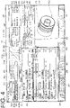
FIG. 4] FIG. 4 illustrates an example display screen of a load display program according to a first embodiment. - [
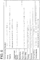
FIG. 5] FIG. 5 is an enlarged view of a sorting criterion selection interface, an order specifying interface, and a tool list window. - [
FIG. 6] FIG. 6 illustrates a cutting power calculation method assigned on a machiningmethod basis. - [
FIG. 7] FIG. 7 illustrates another example display screen of the load display program according to the first embodiment. - [
FIG. 8] FIG. 8 is a flowchart of processing of generating a display screen in a load display method and the load display program. - [
FIG. 9] FIG. 9 illustrates how a tool load time-series graph cooperates with other windows. - [
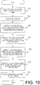
FIG. 10] FIG. 10 is a flowchart of cooperation processing starting from the tool load time-series graph in the load display method and the load display program. - [
FIG. 11] FIG. 11 is a flowchart of processing of changing a cutting condition in the load display method according to the first embodiment and in the load display program. - [
FIG. 12] FIG. 12 illustrates an example window displayed in changing of the cutting condition in the first embodiment. - [
FIG. 13] FIG. 13 is a flowchart of tool exchanging processing in the load display method according to the first embodiment and in the load display program. - [
FIG. 14] FIG. 14 illustrates an example tool data window. - [
FIG. 15] FIG. 15 illustrates part of tool information of a machining tool. - [
FIG. 16] FIG. 16 illustrates an example machining process selection window. - [
FIG. 17] FIG. 17 illustrates an example display screen of a load display program according to a second embodiment. - [
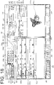
FIG. 18] FIG. 18 illustrates another example display screen of the load display program according to the second embodiment. - [
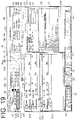
FIG. 19] FIG. 19 illustrates an example window displayed in changing of a cutting condition in the second embodiment. - The present invention will now be described with reference to the accompanying drawings, wherein like reference numerals designate corresponding or identical elements throughout the various drawings.
-
FIG. 1 illustrates a schematic configuration of according to asystem 10 according to this embodiment of the present invention. Thesystem 10 includes amachine tool 100, acomputer 200, and anetwork 290. Thenetwork 290 connects themachine tool 100 and thecomputer 200 to each other. A non-limiting example of thenetwork 290 is a LAN (local area network) provided in a factory, a plant, or another industrial facility. While thenetwork 290 illustrated is a wired network, thenetwork 290 may be a wireless network. It is to be noted that as illustrated inFIG. 1 , the X axis is along the height direction of themachine tool 100, the Y axis is along the depth direction of themachine tool 100, and the Z axis is along the width direction of themachine tool 100. This embodiment is in accordance with a JIS standard in that the Z axis is an axis parallel to rotation axis A3 of afirst spindle 122, which holds a workpiece. In this embodiment, this coordinate system will be referred to as workpiece coordinate system. - The
machine tool 100 performs machining on a workpiece W1. The machining includes at least one of turning, milling, drilling, threading, and spot facing. As illustrated inFIG. 1 , themachine tool 100 includes acolumn 110, afirst headstock 120, and asecond headstock 121. Thecolumn 110, thefirst headstock 120, and thesecond headstock 121 are provided on abase 140. - The
column 110 is movable in the Y axis direction and the Z axis direction on thebase 140. Atool headstock 112 is mounted on thecolumn 110. Thetool headstock 112 is movable in the X axis direction relative to thecolumn 110. Thetool headstock 112 is swingable, relative to thecolumn 110, about a swinging axis A1, which is along the Y axis direction. Atool spindle 114 is mounted on thetool headstock 112. Thetool spindle 114 is rotatable about a rotation axis A2 relative to thetool headstock 112. The rotation axis A2 is orthogonal to the swinging axis A1. Thetool spindle 114 is holding a tool Ta, which is a machining tool. As used herein, the term "machining tool" is intended to mean a concept encompassing a turning tool, a milling tool, a drilling tool, a threading tool, and a spot facing tool. Themachine tool 100 further includes a tool exchanger, not illustrated, that exchanges the tool Ta with another tool. The tool Ta is exchanged as necessary, that is, based on the kind of machining performed on the workpiece W1. - In this embodiment, the intersection between the
axis A 1 and theaxis A 2 will be referred to as machine origin Om; the rotation axis A2 will be referred to as Zm axis; the swinging axis A1 will be referred to as Ym axis; an axis perpendicular to the Zm axis and the Ym axis will be referred to as Xm axis; and a coordinate system defined by these axes will be referred to as machine coordinate system. The direction extending from the machine origin Om toward the leading end of a first tool T1 will be regarded as positive direction of the Zm axis. The X axis of the workpiece coordinate system is rotated about the Y axis such that the positive direction of the X axis of the workpiece coordinate system is identical to the positive direction of the Xm axis of the machine coordinate system. This makes the positive direction of the Z axis of the workpiece coordinate system identical to the positive direction of the Zm axis of the machine coordinate system. The positive direction of the Y axis of the workpiece coordinate system will be regarded as the positive direction of the Ym axis of the machine coordinate system. - The
first headstock 120 is fixed on thebase 140. Thefirst headstock 120 includes thefirst spindle 122. Thefirst spindle 122 is rotatable about the rotation axis A3. The rotation axis A3 is along the Z axis direction. Thefirst spindle 122 includes afirst chuck 124. Thefirst chuck 124 holds a first end of the workpiece W1. Thesecond headstock 121 is provided on thebase 140 and movable on the base 140 in directions parallel to the Z axis direction. Thesecond headstock 121 includes asecond spindle 123. Thesecond spindle 123 is rotatable about the rotation axis A3. Thesecond spindle 123 includes asecond chuck 125. Thesecond chuck 125 holds a second end of the workpiece W1. The second end is opposite to the first end of the workpiece W1 in the Z axis direction. When themachine tool 100 machines the second end of the workpiece W1, thefirst chuck 124 holds the workpiece W1. When themachine tool 100 machines the first end of the workpiece W1, thesecond chuck 125 holds the workpiece W1. - The
machine tool 100 includes acontroller 150. Thecontroller 150 controls rotational motions about the rotation axes, swinging motions about the swinging axis, and movements in the axis directions. Thecontroller 150 is connected to thebase 140. It is to be noted that thecontroller 150 may be connected to another portion of themachine tool 100, or may be provided at a position apart from the base 140 insofar as thecontroller 150 is capable of transmitting control signals and/or receiving detection results. -
FIG. 2 is a hardware block diagram of thecontroller 150. As illustrated inFIG. 2 , thecontroller 150 includes aprocessor 151, amemory 152, acommunication circuit 153, and a touch panel-equippeddisplay 154. Theprocessor 151, thememory 152, thecommunication circuit 153, and the touch panel-equippeddisplay 154 are connected to each other via abus 155. Thememory 152 is a computer-readable storage medium that stores programs necessary for machining, programs necessary for load display, and data necessary for these programs. Thememory 152 may be provided inside thecontroller 150 or may be removable from thecontroller 150. Theprocessor 151 reads a program stored in thememory 152 and executes the program that has been read. In this manner, the functions of thecontroller 150 are implemented. The functions implemented by thecontroller 150 include control of machining. Specifically, thememory 152 stores amachining program 157. Themachining program 157 includes a control command for performing machining. Themachining program 157 is usually edited in thecomputer 200, transmitted to thecontroller 150 via thenetwork 290, and stored in thememory 152. Thecommunication circuit 153 has functions necessary for communicating with thecomputer 200 via thenetwork 290; specifically, a function of converting a communication packet into data, a function of converting data into a communication packet, and a function of transmitting and receiving communication packets. - In this embodiment, the
memory 152stores tool information 158, which is about tools Ta mountable on themachine tool 100. Thetool information 158 includes T numbers corresponding to respective tools Ta, names of respective tools Ta, materials of respective tools Ta, dimensions of respective tools Ta, and usage states (wear states) of respective tools Ta. As used herein, the term "dimensions" of a tool Ta are intended to encompass nominal diameter of the tool Ta, tool length, tool diameter, axial offset, radial offset, teeth count, and cutting edge width. As used herein, the term "tool length" is intended to mean the length of the tool Ta in a direction along the rotation axis A2 (this direction will be hereinafter referred to as axial direction), assuming that the tool Ta is mounted on thetool spindle 114 and that the tool Ta is not worn (that is, the tool Ta is a new tool Ta). In other words, the tool length is the length of the tool Ta in the Zm axis direction in the machine coordinate system. As used herein, the term "tool diameter" is intended to mean the diameter of the tool Ta in a direction perpendicular to the rotation axis A2 (this direction will be hereinafter referred to as radial direction), assuming that the tool Ta is mounted on thetool spindle 114 and that the tool Ta is not worn (that is, the tool Ta is a new tool Ta). As used herein, the term "axial offset" is intended to mean the distance between the tool base of the tool Ta and the tool tip of the tool Ta in the axial direction, assuming that the tool Ta is mounted on thetool spindle 114 and that the tool Ta is not worn (that is, the tool Ta is a new tool Ta). As used herein, the term "tool base" of the tool Ta is intended to mean (assuming that the tool Ta is mounted on the tool spindle 114) one of two end points of the tool Ta in the axial direction that belongs to the portion of the tool Ta held by thetool spindle 114. In other words, the axial offset is the distance in the Zm axis direction between the tool base and the tool tip of the tool Ta in the machine coordinate system. As used herein, the term "radial offset" is intended to mean a coordinate value equivalent to the distance between the tool base of the tool Ta and the cutting edge of the tool Ta in the radial direction, assuming that the tool Ta is mounted on thetool spindle 114 and that the tool Ta is not worn (that is, the tool Ta is a new tool Ta). This coordinate value is the Xm coordinate value of the cutting edge of the tool Ta, assuming that thetool headstock 112 is taking the posture illustrated inFIG. 1 and that the tool Ta is mounted on thetool spindle 114. In order to determine the time to exchange the tool Ta, a user is able to determine the lifetime of the tool Ta and/or tool Ta-duration program count and store lifetime and/or the count in thetool information 158. As used herein, the term "lifetime of the tool Ta" is intended to mean a cumulative total value of the time for which the tool Ta has been used. The cumulative total value is used as a standard of tool Ta exchanging time. As used herein, the term "tool Ta-duration program count" is intended to mean a number indicating how many times themachining program 157 has been executed. The count is used as a standard of tool Ta exchanging time. No matter what kind of program themachining program 157 is, the tool Ta-duration program count is decremented by 1 per execution of themachining program 157 using the tool Ta. - The
memory 152 also includesmaterial information 161, machineconstant data 162, andmachining experience data 163. Thematerial information 161 includes: reference information of the material of the workpiece W1 to be machined (examples including name, material symbol, and ID); and the specific machining resistance value, kc, and the tapping resistivity factor, Kr, of the material. The machineconstant data 162 is a parameter unique to themachine tool 100 used in calculating the load information of the tool Ta. The machineconstant data 162 includes: mechanical efficiency η; motive power correction factor Kc; percentage of thread engagement Pte; thread flank angle α; and thread tapping shape factor K. Themachining experience data 163 is data that records the load that the tool Ta receives when themachining program 157 is executed. Themachining experience data 163 will not be limited to themachining program 157 but may be log data of the tool Ta recorded from the activation time of themachine tool 100. Thetool information 158 and themachining experience data 163 are transmitted by thecommunication circuit 153 to thecomputer 200 via thenetwork 290. Thetool information 158, thematerial information 161, the machineconstant data 162, and themachining experience data 163 are read from thememory 152 at the time when aload display program 156, described later, is executed. - The
load display program 156 further has a function of rewriting part of themachining program 157. Theload display program 156 may have a function of a simulator of themachining program 157. At the time when theprocessor 151 executes theload display program 156, theprocessor 151 may output, as machiningsimulation data 164, a result of a simulation of themachining program 157. Thememory 152 stores themachining simulation data 164. Thememory 152 may have a volatile memory, and themachining simulation data 164 may be stored in the volatile memory. It is to be noted that operations of theload display program 156 will be detailed later. - The touch panel-equipped
display 154 may be asingle display 154 or may be a combination of a plurality of displays. It is to be noted that the "display" of the touch panel-equippeddisplay 154 is a display example, and the "touch panel" of the touch panel-equippeddisplay 154 is an interface example. It is also to be noted that the touch panel-equippeddisplay 154 may be substituted with a combination of: a display without a touch panel; and input devices provided around the display, examples including buttons, switches, a lever, and a pointing device. In this case, the input devices are interface examples. -
FIG. 3 is a hardware block diagram of thecomputer 200. As illustrated inFIG. 3 , thecomputer 200 includes aprocessor 210, amemory 220, acommunication circuit 230, adisplay 240, and aninput interface 250. Theprocessor 210, thememory 220, thecommunication circuit 230, thedisplay 240, and theinput interface 250 are connected to each other via abus 260. Theinput interface 250 is an interface example. For example, theinput interface 250 is a pointing device such as a keyboard and a mouse. It is to be noted that thecomputer 200 may be a combination in which thedisplay 240 and theinput interface 250 are integral to each other. A non-limiting example of such combination is a tablet computer provided with a touch panel-equipped display. It is also to be noted that thedisplay 240 may be a combination of a plurality of displays. - The
memory 220 is a computer 200-readable storage medium that stores themachining program 157, thetool information 158, thematerial information 161, the machineconstant data 162, themachining experience data 163, themachining simulation data 164, aload display program 221, and a program such as an operating system. Thememory 220 may be provided inside thecomputer 200 or may be removable from thecomputer 200. Theload display program 221 has functions substantially identical to the functions of theload display program 156. It is to be noted, however, that the screen display method for displaying theload display program 221 may be partially different from the screen display method for displaying theload display program 156. Theprocessor 210 reads a program stored in thememory 220 and executes the program that has been read. Thememory 220 may have a volatile memory, and themachining simulation data 164 may be stored in the volatile memory. Thecommunication circuit 230 has functions necessary for communicating with thecomputer 200 via thenetwork 290; specifically, a function of converting a communication packet into data, a function of converting data into a communication packet, and a function of transmitting and receiving communication packets. - The
machining program 157 is rewritten using theload display program 221, and thecomputer 200 transmits themachining program 157 thus rewritten to thecontroller 150 using thecommunication circuit 230. Upon execution of theload display program 221, thecomputer 200 receiveslatest tool information 158 and latestmachining experience data 163 from thecontroller 150 using thecommunication circuit 230, and updates thetool information 158 and themachining experience data 163 stored in thememory 220. - Next, content of the
machining program 157 will be described. In this specification, themachining program 157 according to the first embodiment and themachining program 157a according to the second embodiment are described in different program languages and thus use different methods for specifying tools, specifying workpiece motions (rotation and feed rate), and specifying tool motions (linear and curved movements, rotation). Under the circumstances, description will be first made with regard to those respects that are common to themachining program 157 according to the first embodiment and themachining program 157a according to the second embodiment. Then, details of themachining program 157 according to the first embodiment will be described. Details of themachining program 157a will be described in the second embodiment. - Generally, a machining program specifies a tool to be used and specifies motions of the workpiece and the tool for implementing machining using the tool. In this specification, a series of machining work specified by motions of a workpiece and a tool and performed during the time between the calling of the tool by the machining program and the calling of a next tool will be referred to as a machining process. As detailed in the second embodiment, in the
machining program 157a according to the second embodiment, when a tool is called by the machining program and used to cut a workpiece, cutting conditions may change during the time between the calling of the tool and the calling of a next tool. The cutting conditions are defined by the cutting speed at which the tool cuts the workpiece, the cutting depth by which the tool cuts the workpiece, and the feed rate of the workpiece. In this case, among a series of machining work, those machining work performed under the same cutting conditions may be referred to as a machining process. It is to be noted that in themachining program 157 according to the first embodiment, the cutting conditions remain unchanged during the time between the calling of a tool by the machining program and the calling of a next tool. - In the first embodiment, at least the following content is defined in the
machining program 157. - (1) Common unit: Material and shape of pre-machined workpiece W1.
- (2) Basic coordinate unit: Method for setting the workpiece coordinate system and the machine coordinate system.
- (3) Machining unit: Machining methods and machined shapes of parts of final machined shape.
- The common unit, the basic coordinate unit, and the machining unit each include a unit number. The machining unit includes: information for identifying machining content; a tool sequence for setting a tool Ta and cutting conditions of the tool Ta; and a shape sequence for specifying a machined shape obtained in the machining unit. As used herein, the term "tool sequence" is intended to mean a series of machining stages necessary for forming a machined shape (for example, one bar material and one screw hole) of a part specified in the machining unit (examples of the series of machining stages include: a series of stages of rough processing and finishing processing; and in the case of threading, a series of stages of spotting, prepared hole processing, and tapping). In each machining stage, one tool is specified, and cutting conditions are specified. Therefore, in the first embodiment, one stage of the tool sequence corresponds to the above-described machining process. As used herein, the term "shape sequence" is intended to mean a code defining a target shape in the machining unit. For example, in turning, the shape sequence means an aggregation of segments defined by parameters for determining a machined shape, such as: a start point and an end point of the cutting edge of a tool in the workpiece coordinate system; and a connection relationship indicating how the start point and the end point are connected to each other (such as by way of a line or an arc). It is to be noted, however, that the thread pitch is specified in information for identifying the machining content of the machining unit. In the
machining program 157, motions of the workpiece W1 are specified by the machining processes of the tool sequence, and motions of the tool Ta are automatically calculated by themachine tool 100 based on: the tool kind and cutting conditions specified by the machining processes of the tool sequence; the unit name of the machining unit; and the shape sequence. - Thus, the
machining program 157 specifies a plurality of tools Ta used in machining work and at least one machining process included in the machining work performed using each tool of the plurality of tools Ta. In the machining process, the tool Ta and the cutting conditions of the tool Ta for implementing the process of the machining stage are defined. In the at least one machining process, at least one of the following is defined: the cutting depth of the each tool of the plurality of tools Ta relative to the workpiece; the feed rate of the workpiece; the cutting speed of cutting the workpiece; and the rotational speed (spindle rotational speed) of the spindle configured to rotate the workpiece or the each tool. The cutting conditions of the tool Ta in the first embodiment will be defined in more detail. The cutting conditions of the tool Ta include cutting speed Vc, tool rotational speed n, feed rate, and cutting depth. The cutting conditions may be referred to as cutting parameters. The cutting speed Vc (m/min) is obtained from the equation "Vc = π × D nw/1000", where nw (min-1) denotes workpiece spindle rotational speed and D (mm) denotes workpiece diameter. Thus, the cutting conditions of the tool Ta may be regarded as including the workpiece spindle rotational speed nw. The tool rotational speed n and the workpiece spindle rotational speed nw will be collectively and simply referred to as spindle rotational speed. The feed rate includes feed per revolution fr and feed per minute Vf of the spindle. The cutting depth includes at least one of: the axial cutting depth, ap, of the workpiece rotation axis or the tool rotation axis; and the radial cutting depth, ae, of the workpiece rotation axis or the tool rotation axis. Thus, in the first embodiment, the parameters defining the machining process include the tool Ta used, a sign indicating the machining stage, the cutting speed Vc, the spindle rotational speed nw, the tool rotational speed n, the feed rates fr and Vf, and the cutting depths ap and ae. The parameters defining the machining process further include: information for identifying the stage of the machining process (examples including rough processing, finishing processing, spotting, prepared hole processing, and tapping); and a number indicating the order in which the machining process is performed in the machining unit to which the machining process belongs (this number will be hereinafter occasionally referred to as tool sequence number). For example, assume that in themachining program 157, the machining process of rough processing is defined asnumber 1 in the tool sequence and that the machining process of finishing processing is defined asnumber 2 in the tool sequence. Under this assumption, the machining process of rough processing is performed first, and then the machining process of finishing processing is performed. Also, the tool Ta and the cutting conditions of the tool Ta defined in the machining process are applied to the entirety of the shape sequence in the same machining unit. -
FIG. 4 illustrates anexample display screen 30 of theload display program 221 according to this embodiment. Thedisplay screen 30 is displayed on thedisplay 240. It is to be noted that a display screen showing theload display program 156 in the touch panel-equippeddisplay 154 of thecontroller 150 is substantially identical to thedisplay screen 30, with an exception described later. Thedisplay screen 30 includes amachining program name 301, adata status indicator 302, adata selector 303, a datacreation time indicator 304, a sortingcriterion selection interface 305, anorder specifying interface 306, a machiningprocess display interface 307, a machiningprocess non-display interface 308, atool list window 310, a tool characteristics displaywindow 340, a cutting conditions displaywindow 350, a cutpart display window 370, and a tool load time-series graph 380. InFIG. 4 and some later drawings, namely,FIGs. 5 ,7 ,9 ,12 ,14 ,16 ,17 ,18 , and19 , a quadrangle is indicated by dotted lines. This quadrangle is added for display content identifying purposes, and is not displayed on the display 240 (154) in actual situations. - The
machining program name 301 indicates a file name of themachining program 157. At the start time of execution of the load display program 221 (156), a window for specifying themachining program 157 is displayed, and the file name of themachining program 157 specified is displayed as themachining program name 301 on thedisplay screen 30. It is to be noted, however, that when thecontroller 150 and thecomputer 200 include additional information for identifying themachining program 157, themachining program name 301 may be this additional information, instead of the file name. - The
data status indicator 302 indicates whether the update dates of themachining experience data 163 and themachining simulation data 164 are new or old, instead of indicating the update date of themachining program 157 identified by the machining program name 301 (when a reference is made to themachining program 157 in the following description of thedisplay screen 30, themachining program 157 is intended as themachining program 157 identified by themachining program name 301, unless noted otherwise). It is to be noted, however, that when themachining experience data 163 and themachining simulation data 164 do not exist, the update dates are regarded as old.FIG. 4 illustrates a case where while the update date of themachining simulation data 164 is newer than the update date of themachining program 157, themachining experience data 163 does not exist. In thedata status indicator 302, statuses of the update dates of themachining experience data 163 and themachining simulation data 164 are indicated by predetermined pictorial symbols. It is possible, however, to indicate the presence and absence of the data using any other pictorial symbols or text. Also, when none of themachining experience data 163 and themachining simulation data 164 exists, the processor (210) (151) may perform a simulation of themachining program 157 at the start time of execution of the load display program 221 (156), and generate themachining simulation data 164. - The
data selector 303 is an interface for specifying whether to use themachining experience data 163 or themachining simulation data 164 to obtain the load information of the tool Ta.FIG. 4 illustrates a state in which abutton 303a, which is for selecting themachining simulation data 164, and abutton 303b, which is for selecting themachining experience data 163, are displayed as selectable and in which thebutton 303a is selected. It is to be noted, however, that thedata selector 303 may be any other interface insofar as either themachining experience data 163 or themachining simulation data 164 is selectable on the interface. For example, thedata selector 303 may be a graphic user interface (GUI) such as a radio button, a drop-down list, and a list box. - The data
creation time indicator 304 indicates creation date-time 304a of themachining program 157, creation date-time 304b of themachining simulation data 164, and creation date-time 304c of themachining experience data 163. In the example illustrated inFIG. 4 , themachining experience data 163 is not created yet, and its creation date-time 304c is indicated by dashes. - The sorting
criterion selection interface 305 is an interface for selecting a sorting criterion specifying the display order in which the tools Ta are displayed in thetool list window 310.FIG. 5 is an enlarged view of the sortingcriterion selection interface 305 and of theorder specifying interface 306 and thetool list window 310, which will be described later.FIGs. 4 and5 illustrate an example in which the sortingcriterion selection interface 305 is a drop-down list from which any one of the following is selectable: the usage time for which the tool Ta is used; the volume of the cut part that is cut by the tool Ta; the path length of the tool Ta for cutting work; the average value of the cutting power parameter; the peak value of the cutting power parameter; and the cutting work order. It is to be noted, however, that the sortingcriterion selection interface 305 may be any other interface on which the sorting criterion is selectable from any one of the usage time, the volume, the total path length, the average output, the maximum output, and the cutting work order (for example, a radio button, a list box, and a button for selecting one of the above-described options). At the time of activation of the load display program 221 (156), a default value of the sorting criterion is selected. For example, the default value may be the above-described cutting work order, or a prior sorting criterion selected as of the end of execution of the previous load display program 221 (156). In this embodiment, the usage time of tool Ta, the volume of the cut part that is cut by the tool Ta, the path length of the tool Ta for cutting work, the average value of the cutting power parameter corresponding to cutting power applied to tool Ta, and the peak value of the cutting power parameter will be collectively referred to as load information of tool Ta. That is, at least one piece of load information of tool Ta includes at least one of: the usage time for which each tool is used in the machining process; the volume of a cut part that is cut by each tool in the machining process; the length of a path of each tool in the machining process; the average value of the cutting power parameter corresponding to cutting power applied to the tools in the machining process; and the maximum value of the cutting power parameter in the machining process. The usage time and the path length are values affecting the machining time as a whole, and the average value of the cutting power parameter and the peak value of the cutting power parameter are values affecting the tool lifetime. In light of this fact, these values are important for reviewing the machining process. It is to be noted that the load information of the tool Ta selected on the sortingcriterion selection interface 305 will be referred to as selected load information. - The cutting power parameter is a general concept encompassing: an estimated value of the cutting power applied to the tool Ta; and power ratio, which is a ratio between a continuous rated output of a motor that applies the cutting power to the tool Ta and actual output power of the motor for applying the cutting power. That is, the cutting power parameter includes at least one of the estimated value of the cutting power and the power ratio. The cutting power is a value affecting the tool lifetime, and the power ratio is a value that not only affects the tool lifetime but also is helpful in determining whether there is room for increasing the output power of the motor in order to shorten the machining time as a whole. The estimated value of the cutting power applied to tool Ta can be calculated in the manner described below. The nominal diameter of the tool Ta, the tool diameter, the teeth count, Z, and the cutting edge width, which are stored as the
tool information 158, will be denoted as D, Ds, Z, and De, respectively. The specific machining resistance value and the tapping resistivity factor, which are stored as thematerial information 161, will be denoted as kc and Kr, respectively. The mechanical efficiency, the motive power correction factor, the percentage of thread engagement, the flank angle, and the tapping shape factor, which are stored as the machineconstant data 162, will be denoted as η, Kc, Pte, α, and K, respectively. The cutting speed, the feed per revolution, the axial cutting depth of the workpiece rotation axis or the tool rotation axis, and the radial cutting depth of the workpiece rotation axis or the tool rotation axis, which are defined in the machining process, will be denoted as Vc, fr, ap, and ae, respectively. The thread pitch set in the information for identifying the machining content of the machining unit will be denoted as M. With relevant items thus denoted, the estimated value P of the cutting power can be calculated on a machining-kind basis as illustrated inFIG. 6 . That is, the processor (210) (151) is able to calculate the cutting power parameter based on the cutting depths ap and ae, the feed rate fr, and the cutting speed Vc. It is to be noted that the kind of machining is identifiable from the information for identifying the machining content of the machining unit. In performing a simulation of themachining program 157, the processor (210) (151) outputs the estimated value of the cutting power thus calculated to themachining simulation data 164. - The power ratio is obtained in the manner described below. In turning, the cutting power applied to the tool Ta is generated by the motor that rotates one of the
first spindle 122 and thesecond spindle 123 that is holding the workpiece W1. Thus, in turning, the motor that rotates one of thefirst spindle 122 and thesecond spindle 123 that is holding the workpiece W1 is the motor that applies the cutting power to the tool Ta. In this case, the ratio of the output power of this motor to its continuous rated output can be calculated as the power ratio. In milling, drilling, threading, and spot facing, the cutting power applied to tool Ta is generated by the motor that rotates thetool spindle 114. Thus, in milling, drilling, threading, and spot facing, the motor that rotates thetool spindle 114 is the motor that applies the cutting power to the tool Ta. In this case, the ratio of the output power of this motor to its continuous rated output can be calculated as the power ratio. It is to be noted that in milling, drilling, threading, and spot facing, in order to maintain the posture of the workpiece W1 during machining, an output is made also from the motor that rotates one of thefirst spindle 122 and thesecond spindle 123 that is holding the workpiece W1. In this case, themachine tool 100 may: calculate a power ratio for each of the motors that rotate therespective spindles machining experience data 163. - When one of the estimated value of the cutting power and the power ratio is known, the processor (210) (151) may convert the other one of the estimated value of the cutting power and the power ratio in the following manner. In the
machine tool 100, the continuous rated output of each of the motors that rotate therespective spindles constant data 162 includes a table that shows a relationship between the continuous rated output and the rotational speed of each of the motors that rotate therespective spindles spindles machining program 157; or detecting a rotational speed from the output value of a sensor that detects the rotational speed of each of thespindles machine tool 100. The processor (210) (151) may refer to the table to obtain the continuous rated output from the rotational speed obtained. Thus, when the estimated value of the cutting power is known, the processor (210) (151) may obtain the power ratio by dividing the estimated value of the cutting power by the continuous rated output obtained. When the power ratio is known, the processor (210) (151) may obtain the estimated value of the cutting power by multiplying the obtained power ratio by the continuous rated output obtained. That is, the cutting power parameter may be a concept further encompassing the estimated value of the cutting power obtained by multiplying the power ratio output from themachine tool 100 by the continuous rated output. - Upon selection of the average value of the cutting power parameter on the sorting
criterion selection interface 305 with themachining experience data 163 in selected state, the processor (210) (151) reads the power ratio from themachining experience data 163, and obtains the average value of the cutting power parameter for each of all the machining processes performed per execution of themachining program 157. Another possible example is that the processor (210) (151) may read the power ratio from themachining experience data 163, calculate an estimated value of the cutting power, and obtain an average value of the estimated value. Upon selection of the average value of the cutting power parameter on the sortingcriterion selection interface 305 with themachining simulation data 164 in selected state, the processor (210) (151) reads, from themachining simulation data 164, an estimated value of the cutting power or a converted value of the power ratio, and obtains the average value of the cutting power parameter for each of all the machining processes performed per execution of themachining program 157. Then, based on the tool Ta used in the machining process, the processor (210) (151) assigns the obtained average value on a tool-Ta basis. Then, the processor (210) (151) determines the display order in which the tools Ta are displayed in thetool list window 310. In determining the display order, the processor (210) (151) uses, as a reference, the largest value of average values of more than one machining process assigned on a tool-Ta basis. Thus, the processor (210) (151) performs processing of: calculating at least one piece of load information in the at least one machining process performed using each tool; obtaining a maximum value of values of the selected load information in all the at least one machining process performed using the tools; and displaying the plurality of tools in turn based on the maximum value. Obtaining a sum of average values of the selected load information may result in a large value of sum if there is a large number of machining processes, even if the average value of the selected load information in an individual machining process is small. In this case, it is difficult to review the machining process. In light of this, the maximum value of average values assigned on a tool-Ta basis is used as a reference. This makes it easier to find a machining process to be reviewed. - In the case where the peak value of the cutting power parameter is selected on the sorting
criterion selection interface 305, the processing performed is approximately the same as the processing performed in the case where the average value of the cutting power parameter is selected. The processor (210) (151) obtains the cutting power parameter for each of all the machining processes performed per execution of themachining program 157. In obtaining the cutting power parameter, the processor (210) (151) uses a method similar to the method used when the average value of the cutting power parameter is selected from themachining experience data 163 or themachining simulation data 164. Then, the processor (210) (151) obtains the peak value of the obtained cutting power parameter for each of all the machining processes performed per execution of themachining program 157. Then, based on the tool Ta used in the machining process, the processor (210) (151) assigns the obtained peak value on a tool-Ta basis. The processor (210) (151) determines the display order in which the tools Ta are displayed in thetool list window 310. In determining the display order, the processor (210) (151) uses, as a reference, the largest value of the peak values of more than one machining process assigned on a tool-Ta basis. In this case as well, theprocessor 210 can be regarded as performing processing of: calculating at least one piece of load information in the at least one machining process performed using each tool; obtaining a maximum value of values of the selected load information in all the at least one machining process performed using the tools; and displaying the plurality of tools in turn based on the maximum value. This case is also similar to the above-described case in that the effect of making it easier to find a machining process to be reviewed is provided. - The volume of the cut part that is cut by the tool Ta is calculated from: the shape of a 3D model of the post-machined workpiece W1 related to the machining unit; and the shape of the pre-machined workpiece W1 defined in the common unit. In executing the
machining program 157, themachine tool 100 outputs the value of the volume as themachining experience data 163. In performing a simulation of themachining program 157, the processor (210) (151) outputs the volume of the cut part thus calculated to themachining simulation data 164. Thus, when the volume of the cut part that is cut by the tool Ta is selected on the sortingcriterion selection interface 305, the processor (210) (151) extracts, from themachining experience data 163 or themachining simulation data 164, volumes of cut parts for all the machining processes performed per execution of themachining program 157. Then, the processor (210) (151) assigns the volumes on a tool-Ta basis. Then, the display order in which the tools Ta are displayed in thetool list window 310 is determined based on the sum of the volumes of the cut part assigned on a tool-Ta basis.
the path length of the tool Ta for cutting work can be calculated from: the shape of the pre-machined workpiece W1 defined in the common unit; the cutting depths ap and ae obtained from the machining process in which the tool Ta is used; the dimensions and worn state of the tool Ta obtained from thetool information 158; and the post-machined surface shape obtained from the shape sequence included in the same machining unit in which the tool sequence in which the tool Ta is used is included. For example, as recited inJP 2006- 053945A machining program 157, themachine tool 100 outputs an actual tool path as themachining experience data 163. In performing a simulation of themachining program 157, the processor (210) (151) outputs the above-determined tool path to themachining simulation data 164. Thus, when the path length of the tool Ta for cutting work is selected on the sortingcriterion selection interface 305, the processor (210) (151) reads the actual path of the tool Ta from themachining experience data 163 or reads, from themachining simulation data 164, the tool path obtained by a calculation. Then, the processor (210) (151) obtains tool paths for all the machining processes performed per execution of themachining program 157, and obtains path lengths of the respective tool paths. Then, the processor (210) (151) assigns the obtained path lengths on a tool-Ta basis. Then, the display order in which the tools Ta are displayed in thetool list window 310 is determined based on the sum of the path lengths assigned on a tool-Ta basis. - The usage time of tool Ta may be calculated by dividing the above-described path length by the feed per minute Vf. Thus, when the usage time of tool Ta is selected on the sorting
criterion selection interface 305, the processor (210) (151) may calculate the path length by the above-described method for each of all the machining processes performed per execution of themachining program 157, and obtain the usage time from the path length based on the feed per minute Vf. Another possible example is that in executing themachining program 157, themachine tool 100 may relate an actual tool position to the work time and output them as themachining experience data 163. Thus, the processor (210) (151) may read themachining experience data 163 and obtain the usage time for each of all the machining processes performed per execution of themachining program 157. Then, the processor (210) (151) assigns the obtained usage time on a tool-Ta basis. Then, the display order in which the tools Ta are displayed in thetool list window 310 is determined based on the sum of the usage times assigned on a tool-Ta basis. - The cutting work order in the machining processes is determined by the machining unit calling order in the
machining program 157 and a number indicating the order in which the machining processes in the machining unit are performed. While the machining unit calling order in themachining program 157 is generally in unit numerical order of themachining program 157, the machining unit calling order may not necessarily be in this order. Thus, when the cutting work order is selected on the sortingcriterion selection interface 305, the processor (210) (151) assigns the cutting work order determined by the above-described method on a tool-Ta basis for each of all the machining processes performed per execution of themachining program 157. Then, the display order in which the tools Ta are displayed in thetool list window 310 is determined based on the earliest work order among the work orders assigned on a tool-Ta basis. - The
order specifying interface 306 is an interface for specifying, based on the sorting criterion selected on the sortingcriterion selection interface 305, the order (decreasing order/ascending order) in which the tools Ta are displayed in thetool list window 310. At the time of activation of the load display program 221 (156), the order selected as a default value is, for example, decreasing order or a prior order selected as of the end of execution of the previous load display program 221 (156).FIGs. 4 and5 illustrate an example in which the usage time of tool Ta is selected as the sorting criterion on the sortingcriterion selection interface 305, and decreasing order is specified on theorder specifying interface 306. In these figures, theorder specifying interface 306 is displayed in the form of an icon of a pointing-down triangle. Upon manipulation of theorder specifying interface 306 by way of an operation such as tapping and clicking, an icon of a pointing-up triangle is displayed and ascending order is specified. It is to be noted that theorder specifying interface 306 will not be limited to the display form illustrated inFIGs. 4 and5 but may be displayed in any other GUI form such as radio button, drop-down list, and list box. - Referring to
FIG. 5 , thetool list window 310 includes a tooloverview display window 311 and a machiningprocess display window 312. The tooloverview display window 311 displays: thetool information 158 of each tool Ta; the sum of the usage times for which the tools Ta have been used in the machining process; the sum of the volumes of the cut parts cut using the tools Ta in the machining process; and the largest value of the average values of the cutting power parameter in the machining process in which the tools Ta are used. The tooloverview display window 311 may display information other than the above-described information. For example, the tooloverview display window 311 may display the largest value of the peak values of the cutting power parameter in the machining process in which the tools Ta are used. - In an upper left corner portion of the
tool list window 310,T numbers 313 are displayed. The T numbers 313 correspond to the respective tools Ta. On the right side of theT numbers 313,symbols 314 are displayed. Thesymbols 314 schematically show the respective tools Ta. Thesymbols 314 may be omitted. On the right side of thesymbols 314,tool names 315 of the respective tools Ta are displayed. For some of the tools, such as a turning tool, aname 316 of a machined part is displayed on the right side of eachtool name 315. On the right side of the tool names 315 (or thenames 316, when there are names 316),numerical values 317 are displayed. Eachnumerical value 317 is a value of the size or nominal diameter of each tool Ta. A decimal point is added at the end of eachnumerical value 317, meaning that the part of the value on the left side of the decimal point is in mm units. In the example illustrated inFIGs. 4 and5 , size is displayed at the turning tool and the touch sensor (which are displayed inwindows numerical value 317 depends on the kind of the tool. - Some tools Ta use different cutting edges to allow for different kinds of machining. In order to manage such cutting edges, it is possible to: identify the tool Ta using the integer part of the T number (or predetermined digits from the left); and specify a different end surface using the decimal point and the right side of the decimal point (or digits after the predetermined digits). A sign specifying such end surface will be referred to as suffix. Another possible example is to combine the numerical value of a T number and the suffix and use the combination to specify one tool Ta. In
FIG. 5 ,suffixes 318 are displayed on the right side of thenumerical values 317. While thesuffixes 318 are in alphabetical notation, when thesuffixes 318 are input into the program code as T numbers, ABC ... Z are respectively converted into "01", "02", "03" ... "26", or ABC ... Z are respectively converted into "61", "62", "63" ... " 86". - In a lower half portion of the
tool list window 310, bar charts are 319, 320, and 321 are displayed. In thebar chart 319, a maximum value is displayed that corresponds to the sum (maximum total usage time) of the usage times of the tool that is used for the longest time in themachining program 157. In thebar chart 320, a maximum value is displayed that corresponds to the sum (maximum total cutting volume) of the volumes of cut parts of the workpiece W1 cut by the tool is used to cut the largest volume of the workpiece W1 in themachining program 157. In thebar chart 321, a maximum value is displayed that corresponds topower ratio 200%, among the cutting power parameters. The bar length of thebar chart 319, the bar length of thebar chart 320, and the bar length of thebar chart 321 respectively correspond to: a ratio of the sum of the usage times of the tool Ta used in each machining process to the maximum total usage time; a ratio of the sum of the volumes of the cut part in each machining process in which the tool Ta is used to the maximum total cutting volume; and a ratio of the largest value of the average values of the cutting power parameter in the machining process in which the tool Ta is used topower ratio 200%. It is to be noted that as indicated bylegend 403 inFIG. 16 , it is possible to display, in thetool list window 310, a bar chart of a ratio of the largest value of the peak values of the cutting power parameter in the machining process in which each tool Ta is used topower ratio 200%. - In the example illustrated in
FIG. 5 , the usage time of the end mill is maximum, and thus it is at the end mill that the bar length of thebar chart 319 is at its maximum value. The bar length of thebar chart 319 in each tool of the other tools is determined based on a ratio of the total usage time of the each tool to the total usage time of the end mill. Further, in the example illustrated inFIG. 5 , the volume of the cut part that is cut by the face mill is maximum, and thus it is at the face mill that the bar length of thebar chart 320 is at its maximum value. The bar length of thebar chart 320 in each tool of the other tools is determined based on a ratio of the sum of the volumes of the cut part that is cut by the each tool to the sum of the volumes of the cut part that is cut by the face mill. By displaying thebar charts bar chart 321, it becomes unnecessary for the user to refer to the machiningprocess display window 312 in obtaining knowledge of, in the machining process associated with each tool Ta, relative magnitude of the load information in the bar charts. - In a upper right end portion of the tool
overview display window 311, a machining process display/non-display interface 322 is displayed. For the tools in the tooloverview display windows process display window 312 is displayed. For these windows, machiningprocess display interfaces 322a are displayed. The machiningprocess display interface 322a is an interface for displaying the machiningprocess display window 312. Upon manipulation of the machiningprocess display interfaces 322a by way of an operation such as tapping and clicking, the machiningprocess display window 312 of the tool corresponding to the tooloverview display window 311 is displayed, as in the tooloverview display window 311b. - For the tool of the tool
overview display window 311b, the machiningprocess display window 312 is displayed. For thewindow 311b, a machiningprocess non-display interface 322b is displayed. The machiningprocess non-display interface 322b is an interface for making the machiningprocess display window 312 into non-display (hidden) state. Upon manipulation of the machiningprocess non-display interface 322b by way of an operation such as tapping and clicking, the machiningprocess display window 312 displayed disappears. - Above the
tool list window 310, the machiningprocess display interface 307 and the machiningprocess non-display interface 308 are displayed. The machiningprocess display interface 307 is an interface for the machiningprocess display windows 312 of all tools. The machiningprocess non-display interface 308 is an interface for making the machiningprocess display windows 312 of all tools into non-display state. Upon manipulation of the machiningprocess display interface 307 by way of an operation such as tapping and clicking, all the tools displayed in the tool list window 310 (all the tools used in the machining program 157) are displayed in the machiningprocess display window 312. Upon manipulation of the machiningprocess non-display interface 308 by way of an operation such as tapping and clicking, the machiningprocess display windows 312 of all the tools displayed in the tool list window 310 (all the tools used in the machining program 157) disappear. - In
FIGs. 4 and5 , the machining process display interfaces 307 and 322a are icons of pointing-down arrow heads, and the machining processnon-display interfaces non-display interfaces - When one tool is used in a plurality of machining processes, a plurality of machining
process display windows 312 are displayed according to the sorting criterion selected on the sortingcriterion selection interface 305 in the machining process and in the order specified by theorder specifying interface 306. In the example illustrated inFIG. 5 , the usage time of tool Ta is selected as the criterion and decreasing order is specified. In this respect, the machiningprocess display window 312a is a window for one machining process that is one of two machining processes in which the turning tool ofT number 7 is used and that has a longer usage time. Accordingly, the machiningprocess display window 312a is displayed at a position upper than the machiningprocess display window 312b, which is a window for the other machining process having a shorter usage time. - In the machining
process display window 312, ausage time 323 is displayed under thebar chart 319. Theusage time 323 is the time for which the corresponding tool Ta is used in the machining process. Under thebar chart 321, a cuttingpower parameter 324 in the machining process is displayed. While inFIGs. 4 and5 power ratio is displayed as the cutting power parameter, a conversion value of cutting power may be displayed. While no item is displayed under thebar chart 320, the volume of the cut part in the machining process may be displayed. - On the right side of the cutting
power parameter 324, aspindle number 325 is displayed. Thespindle number 325 indicates whether the workpiece W1 is held by thefirst spindle 122 or thesecond spindle 123. As thespindle number 325, a number (for example, "1") identifying thefirst spindle 122 or a number (for example, "2") identifying thesecond spindle 123 is displayed. - On the right side of the
spindle number 325, aunit number 326 is displayed. Theunit number 326 is for identifying the machining process including the machining unit. On the right side of theunit number 326,information 327 is displayed. Theinformation 327 is for identifying the machining content of the machining unit corresponding to theunit number 326. On the right side of theinformation 327, the stage, 328, of the machining process is displayed. InFIG. 5 , "R1" indicates that rough processing is performed and that the tool sequence number of the rough processing is 1; and "F2" indicates that finishing processing is performed and that the tool sequence number of the finishing processing is 2. In threading, pieces of information respectively indicating spotting, prepared hole processing, and tapping may be displayed in thestage 328. - In a right end portion of the
tool list window 310, ascroll bar 329V is displayed. In a lower end portion of thetool list window 310, ascroll bar 329H is displayed. By moving thescroll bar 329V, the user is able to cause the tooloverview display window 311 and the machiningprocess display window 312 of a desired tool Ta to be displayed. By moving thescroll bar 329H, the user is able to cause other information of the machining process to be displayed in the machiningprocess display window 312. The other information of the machining process may include, for example, coordinates of an approach point of the tool Ta at the start of the machining process. - In the
tool list window 310, either the tooloverview display window 311 or the machiningprocess display window 312 is selectable. Upon manipulation of the tooloverview display window 311 by way of an operation such as tapping and clicking, the processor (210) (151) regards the manipulated tooloverview display window 311 as the selected tooloverview display window 311, and performs processing of highlighting this tooloverview display window 311. In this embodiment, the tool Ta corresponding to the selected tooloverview display window 311 will be referred to as selected tool. Then, upon selection of the selected tool displayed as one of the plurality of tools Ta, the processor (210) (151) performs processing of displaying a characteristic of the selected tool in the tool characteristics displaywindow 340. Further, in a state in which no machining process in which the tool Ta corresponding to the selected tooloverview display window 311 is used is selected, the processor (210) (151) performs processing of displaying, in the cutting conditions displaywindow 350, cutting conditions common to the machining processes displayed in all the machiningprocess display windows 312. It is to be noted thatFIG. 7 illustrates an example of thedisplay screen 30 in a state in which no machining process is selected. Next, the processor (210) (151) performs processing of displaying, in the cutpart display window 370, the shape of a part that is machined in all the machining processes in which the selected tool is used. That is, upon selection of the selected tool displayed as one of the plurality of tools Ta, the processor (210) (151) performs processing of displaying the machined part of the workpiece W1 machined using the selected tool in all the machining processes in which the selected tool is used. Upon selection of the selected tool displayed as one of the plurality of tools, the processor (210) (151) performs processing of highlighting, in the tool load time-series graph 380, a period of time in which all the machining processes in which the selected tool is used are performed. - Upon manipulation of the machining
process display window 312 by way of an operation such as tapping and clicking, the processor (210) (151) regards the manipulated machiningprocess display window 312 as the selected machiningprocess display window 312, and performs processing of highlighting the selected machiningprocess display window 312. In this embodiment, the machining process corresponding to the selected machiningprocess display window 312 will be referred to as selected machining process. Then, the processor (210) (151) performs processing of displaying, in the tool characteristics displaywindow 340, a characteristic of the tool Ta used in the selected machining process. In this embodiment, the tool Ta used in the selected machining process will be referred to as in-use tool. Further, the processor (210) (151) performs processing of displaying cutting conditions for the selected machining process in the cutting conditions displaywindow 350. That is, the processor (210) (151) performs processing of, upon selection of the selected machining process displayed as one of the at least one machining process, displaying at least one of the cutting depth, the feed rate, the cutting speed, and the rotational speed of the spindle in association with the selected machining process. More specifically, the processor (210) (151) performs processing of displaying, upon selection of the selected machining process displayed as one of the at least one machining process, the cutting depth, the feed rate, and the cutting speed associated with the selected machining process. The processor (210) (151) performs processing of displaying, in the cutpart display window 370, the shape of the part machined in the selected machining process. That is, the processor (210) (151) performs processing of displaying, upon selection of the selected machining process displayed as one of the at least one machining process, the machined part of the workpiece W1 machined using the in-use tool used in the selected machining process. Upon selection of the selected machining process displayed as one of the at least one machining process, the processor (210) (151) performs processing of highlighting, in the tool load time-series graph 380, the period of time in which the selected machining process is performed.FIGs. 4 and5 illustrate a state in which the machiningprocess display window 312a is selected. Display contents of the tool characteristics displaywindow 340, the cutting conditions displaywindow 350, the cutpart display window 370, and the tool load time-series graph 380 will be described in detail below. - As described above, the tool characteristics display
window 340 displays a characteristic of the tool Ta (selected tool) displayed in the selected tooloverview display window 311 or a characteristic of the tool Ta (in-use tool) used in the machining process (selected machining process) corresponding to the selected machiningprocess display window 312. The characteristic of the tool Ta includes at least one of the following stored in the tool information 158: the material of the tool Ta; the dimension of the tool Ta; the usage state (worn state) of the tool Ta; the lifetime of the tool Ta; and the tool Ta-duration program count. That is, the processor (210) (151) performs processing of displaying, together with the characteristic of the selected tool, at least one of the lifetime of the selected tool and the number indicating how many times the selected tool is usable in themachining program 157. Alternatively, the processor (210) (151) performs processing of displaying, together with the characteristic of the in-use tool, at least one of the lifetime of the in-use tool and the number indicating how many times the in-use tool is usable in themachining program 157. InFIG. 4 , the tool characteristics displaywindow 340 is displaying: the material, 341, of the tool Ta; the axial offset, 342, of the tool Ta; the radial offset, 343, of the tool Ta; the lifetime, 344, of the tool Ta; and the tool Ta-duration program count, 345. In the tool characteristics displaywindow 340, however, some of these pieces ofinformation 341 to 345 may be omitted, or a characteristic of another tool Ta may be displayed. InFIG. 4 , the tool characteristics displaywindow 340 is displaying the material, axial offset, and radial offset of the turning tool ofT number 7. Since no lifetime and duration program count are set for the turning tool, thelifetime 344 and theduration program count 345 are indicated by dashes. - The tool characteristics display
window 340 displays, asnecessary time 346, the sum of the usage times for which the tool Ta has been used per execution of themachining program 157. Referring toFIG. 5 , the usage time of the tool Ta used in the machining process corresponding to the machiningprocess display window 312a is 3 minutes and 17 seconds; and the usage time of the tool Ta used in the machining process corresponding to the machiningprocess display window 312b is 9 seconds. Therefore, thenecessary time 346 displayed in the tool characteristics displaywindow 340 inFIG. 4 is 3 minutes and 26 seconds. When the tool Ta has a lifetime set, the tool characteristics displaywindow 340 may display aratio 347 of thenecessary time 346 tolifetime 344. This enables the user to know a standard indicating how many times the tool Ta is usable in themachining program 157. - As described above, in a state in which no machining process in which the selected tool is used is selected, the cutting conditions display
window 350 displays cutting conditions common to the machining processes displayed in all the machiningprocess display windows 312 corresponding to the selected tool. When the machiningprocess display window 312 is selected, the cutting conditions displaywindow 350 displays cutting conditions for the selected machining process. InFIG. 4 , the cutting conditions displaywindow 350 is displayingcutting speed 351, feed perrevolution 352, and cuttingdepth 353. That is, upon selection of the selected machining process displayed as one of the at least one machining process, the processor (210) (151) performs processing of displaying at least one of the following that correspond to the selected machining process: the cuttingdepth 353; thefeed rate 352; thecutting speed 351; and the rotational speed of the spindle. In the cutting conditions displaywindow 350, however, some of these pieces ofinformation 351 to 353 may be omitted or other cutting conditions may be displayed. InFIG. 4 , the cutting conditions displaywindow 350 is displaying cutting conditions for the machining process corresponding to the machiningprocess display window 312a. InFIG. 7 , for the turning tool ofT number 7, which is the selected tool, thecutting speed 351, the feed perrevolution 352, thecutting depth 353 are common to rough processing and finishing processing. Each of these pieces of information is common in terms of a parameter and, as such, displayed in the window. However, each information has different values and therefore are not displayed on thedisplay screen 30. - Referring to
FIG. 4 , the cutting conditions displaywindow 350 displays acontrast graph 355. Thecontrast graph 355 is a graph that displays: the cuttingspeeds 351 and the feed perrevolutions 352 respectively corresponding to all the machining processes in which the selected tool is used when the tooloverview display window 311 is selected; and the cutting speeds 351 and the feed perrevolutions 352 respectively corresponding to all the machining processes in which the in-use tool is used when the machiningprocess display window 312 is selected. When the machiningprocess display window 312 is selected, thecontrast graph 355 displays: the cutting speed and the feed rate corresponding to the selected machining process; and the cutting speed and the feed rate corresponding to a machining process different from the selected machining process in which the in-use tool is used. Thecontrast graph 355 displays the cutting speeds and the feed rates in such a form that the cutting speeds are comparable with each other and the feed rates comparable with each other. That is, the processor (210) (151) performs processing of displaying the cutting speed and the feed rate corresponding to the selected machining process and the cutting speed and the feed rate corresponding to a different machining process different from the selected machining process in which each tool is used wherein the cutting speeds and the feed rates are displayed in such a form that the cutting speeds are comparable with each other and the feed rates are comparable with each other. The horizontal axis of thecontrast graph 355 is thecutting speed 351, and the vertical axis of thecontrast graph 355 is the feed perrevolution 352. In the contrast graph, cutting conditions for the machining process of rough processing are indicated by a quadrangle, and cutting conditions for the machining process of finishing processing are indicated by a triangle. As used herein, the phrase "in such a form that the cutting speeds are comparable with each other and the feed rates are comparable with each other" is intended to mean enlarging graphical representations of the cutting speed and the feed rate corresponding to the selected machining process or displaying the graphical representations in different colors.FIG. 4 illustrates an example in which graphical representations of the cutting conditions for the selected machining process are enlarged. It is to be noted that as illustrated inFIG. 7 , in a state in which no machining process in which the selected tool is used is selected, graphical representations of the cutting conditions for all the machining processes are displayed in an identical form. That is, graphical representations of the cutting conditions for all the machining processes in which the selected tool is used are displayed without changes in size and color, as opposed to the above-described configuration. Thecontrast graph 355 is displaying numerical values of the maximum value of thecutting speed 351 displayed and the maximum value of the feed perrevolution 352 displayed. This enables the user to easily compare another machining process associated with the in-use tool with the selected machining process. - The cut
part display window 370 displays: afinal product shape 371, which is obtained as a result of themachining program 157; and the shape of the part that is machined in all the machining processes in which the selected tool is used or the shape of the part machined in the selected machining process. That is, the cutpart display window 370 displays: the machined part of the workpiece W1 machined using the selected tool; or the machined part of the workpiece W1 machined using the in-use tool in the selected machining process. InFIG. 4 , the machined part of the workpiece W1 machined using the selected tool is indicated by a bold line withlegend 372. InFIG. 7 , the machined part of the workpiece W1 machined using the selected tool is indicated by a bold line withlegend 372a. Such parts are subject to change in line boldness and/or color. The processor (210) (151) may obtain thefinal product shape 371 by obtaining the shape of the pre-machined workpiece W1 from the common unit and obtaining machined shapes from the shape sequences of all the machining units. Also, the processor (210) (151) may obtain the machined shape to be displayed from the shape sequence of the machining unit in which all the machining processes in which the selected tool is used are included or from the shape sequence the machining unit in which the selected machining process is included. - The tool load time-
series graph 380 is a graph that shows a cutting power parameter of the tool in a time-series manner from the start to the end of execution of themachining program 157. That is, the processor (210) (151) displays a graph that shows, in a time-series manner from the start to the end of themachining program 157, a cutting power parameter corresponding to the cutting power applied to each tool. In this example, the tool load time-series graph 380 displays changes in the power ratio. The tool load time-series graph 380, however, may be a graph that shows the conversion value of the cutting power in a time-series manner. In the tool load time-series graph 380,solid line 381 indicates the cutting power parameter in a case where the workpiece W1 is mounted on thefirst spindle 122.Dotted line 382 indicates the cutting power parameter in a case where thetool spindle 114 is rotated. Single-dashedline 383 indicates the cutting power parameter in a case where the workpiece W1 is mounted on thesecond spindle 123. In the tool load time-series graph 380,vertical line 384 indicates a time point of switch to another machining process. In the tool load time-series graph 380, an highlightedarea 385 indicates a period of time in which all machining processes in which the selected tool is used are performed, or indicates a period of time in which the selected machining process is performed. InFIG. 4 , the highlightedarea 385 corresponds to a period of time in which the machining process corresponding to the machiningprocess display window 312a is performed. As illustrated inFIG. 7 , when the tooloverview display window 311 is selected and there are a plurality of machining processes in which the selected tool is used, a period oftime 385a, in which all the plurality of machining processes are performed, is highlighted. -
FIG. 8 is a flowchart of processing of generating thedisplay screen 30 in the load display method according to this embodiment and the load display program 221 (156). First, the processor (210) (151) reads themachining program 157 specified by the user at the start time of execution of the load display program 221 (156) (step S1). That is, the processor (210) (151) inputs a plurality of tools Ta used in machining work and themachining program 157, which specifies at least one machining process included in the machining work performed using each tool of the plurality of tools. The processor (210) (151) performs processing of: analyzing the shape sequences of the common unit and the machining units in themachining program 157; preparing three-dimensional shape data of the final product; and displaying the data in the cut part display window 370 (step S2). Next, the processor (210) (151) checks whether themachining experience data 163 or themachining simulation data 164 exists (step S3). When neither data exists (No at step S3), the processor (210) (151) executes a simulator to generate the machining simulation data 164 (step S4). That is, the processor (210) (151) calculates at least one piece of load information for each tool based on themachining program 157. When the result at step S3 is Yes or after performing step S4, the processor (210) (151) displays thedata status indicator 302 and receives an input from thedata selector 303. The processor (210) (151) selects, from themachining experience data 163 and themachining simulation data 164, data used to generate thetool list window 310 based on the input from the data selector 303 (step S5). - Upon selection of the data at step S5, the processor (210) (151) sets a sorting criterion based on a default value of the sorting
criterion selection interface 305 and a default value of theorder specifying interface 306. The sorting criterion is set from the usage time of tool Ta, the volume of the cut part that is cut by the tool Ta, the path length of the tool Ta for cutting work, the average value of the cutting power parameter, the peak value of the cutting power parameter, and the cutting work order. Then, the processor (210) (151) sets an order, which is ascending order or decreasing order (step S6). Upon receipt of an input the sortingcriterion selection interface 305 and/or the order specifying interface 306 (Yes at step S7), the processor (210) (151) re-sets the sorting criterion and the order based on the input (step S6). When there is no input from the sortingcriterion selection interface 305 and the order specifying interface 306 (No at step S7), the procedure proceeds to step S8. - At step S8, the processor (210) (151) performs processing of displaying the
tool list window 310 based on the sorting criterion and the order set at step S6. That is, the processor (210) (151) performs processing of displaying the plurality of tools in turn on the display 240 (154) based on the value of the selected load information, which is one of the at least one piece of load information. Although only the tooloverview display window 311 is displayed in thetool list window 310 immediately after activation of the load display program 221 (156), the machiningprocess display window 312 is displayed by manipulating the machining process display interfaces 307 and 322a. That is, the processor (210) (151) performs processing of displaying, on the display 240 (154) and next to the each tool of the plurality of tools Ta, at least one machining process performed using the each tool. - Next, the processor (210) (151) receives a manipulation such as clicking and tapping on the tool
overview display window 311 or the machining process display window 312 (step S9). The processor (210) (151) regards the manipulated tooloverview display window 311 or the manipulated machiningprocess display window 312 as the selected tooloverview display window 311 or the selected machiningprocess display window 312. The processor (210) (151) regards the tool Ta corresponding to the selected tooloverview display window 311 as the selected tool. The processor (210) (151) treats the machining process corresponding to the selected machiningprocess display window 312 as the selected machining process. - When no manipulation has been made at step S9 (No at step S9), the processor (210) (151) waits without displaying anything in the tool characteristics display
window 340, the cutting conditions displaywindow 350, the cutpart display window 370, and the tool load time-series graph 380. When a manipulation has been made (Yes at step S9), the processor (210) (151) performs processing of displaying the tool characteristics displaywindow 340 associated with the selected tool or the in-use tool used in the selected machining process. Then, upon manipulation of the tooloverview display window 311, the processor (210) (151) performs processing of displaying, in the cutting conditions displaywindow 350, the cutting conditions common to all the machining processes associated with the selected tool. Upon manipulation of the machiningprocess display window 312, the processor (210) (151) performs processing of displaying the cutting conditions displaywindow 350 associated with the selected machining process. Further, upon manipulation of the tooloverview display window 311, the processor (210) (151) performs processing of: displaying, in the cutpart display window 370, the shape of the part machined in all the machining processes in which the selected tool is used; and highlighting, in the tool load time-series graph 380, the time for which all the machining processes are performed. Upon manipulation of the machiningprocess display window 312, the processor (210) (151) performs processing of: displaying, in the cutpart display window 370, the shape of the part machined in the selected machining process; and highlighting, in the tool load time-series graph 380, the time for which the selected machining process is performed (a series of these processings are performed at step S10). - Next, the processor (210) (151) waits for a program ending demand (step S11). As used herein, the term "program ending demand" is intended to mean an ending event in which the load display program 221 (156) ends. When there is no program ending demand (No at step S11), the procedure returns to step S7. When there is a program ending demand (Yes at step S11), the load display program 221 (156) ends.
- In the above-described embodiment, a cooperation between the
tool list window 310 andother windows series graph 380 to cooperateother windows vertical line 384 of the tool load time-series graph 380 indicates a time point of switch between a machining process and a machining process. The processor (210) (151) manages a sectional area between avertical line 384 and avertical line 384 in relation to a machining process. The sectional area corresponds to the period of time in which the related machining process is performed. That is, in the tool load time-series graph 380, the processor (210) (151) manages at least one period of time in which at least one machining process is performed. As illustrated inFIG. 9 , upon manipulation of the sectional area by way of an operation such as tapping and clicking, the processor (210) (151) performs processing of: highlighting, in thetool list window 310, the machining process corresponding to the sectional area; displaying, in the tool characteristics displaywindow 340, a tool characteristic of the tool Ta used in the machining process; displaying cutting conditions for the machining process in the cutting conditions displaywindow 350; and displaying, in the cutpart display window 370, the shape of the part machined in the machining process. - A prerequisite of this cooperation processing is that in displaying the tool load time-
series graph 380 at step S10 ofFIG. 8 , the processor (210) (151) correlates the sectional area and the machining process and stores resulting correlation data in the memory 220 (152). When the tool load time-series graph 380 can be enlarged and reduced in size by manipulations such as pinching to zoom out, pinching to zoom in, and mouse wheeling, the processor (210) (151) correlates the sectional area with the machining process in accordance with the enlargement and/or reduction in size of the tool load time-series graph 380, and stores resulting correlation data in the memory 220 (152).FIG. 10 is a flowchart of cooperation processing performed after the correlation and performed in the load display method according to this embodiment and the load display program 221 (156). First, the processor (210) (151) receives an input manipulation such as clicking and tapping made with respect to the sectional area in the tool load time-series graph 380 (step S21). Then, the processor (210) (151) highlights the sectional area in the tool load time-series graph 380 (step S22). This highlighted area corresponds to the highlightedsectional area 385 inFIG. 9 . In this embodiment, the period of time corresponding to the highlightedsectional area 385 will be referred to as selected period of time. - Next, the processor (210) (151) refers to the correlation data to obtain the machining process corresponding to the
sectional area 385. Then, the processor (210) (151) performs processing of highlighting, in thetool list window 310, the machiningprocess display window 312 corresponding to the machining process corresponding to the sectional area 385 (step S23). That is, upon selection of the selected period of time as one of the at least one period of time, the processor (210) (151) performs processing of highlighting the machining process corresponding to the selected period of time. Then, the processor (210) (151) performs processing of displaying, in the cutting conditions displaywindow 350, cutting conditions for the machining process corresponding to the sectional area 385 (step S24). More specifically, the processor (210) (151) performs processing of displaying the cutting depth, the feed rate, and the cutting speed associated with the machining process corresponding to the selected period of time. The example illustrated inFIG. 9 is different from the example illustrated inFIG. 4 in that: the machining process corresponding to thesectional area 385 is rough processing performed using the end mill ofT number 4; the machiningprocess display window 312c corresponding to the machining process is highlighted; and cutting conditions for the machining process are displayed in the cutting conditions displaywindow 350. InFIG. 9 , since the selected machining process is milling, the cutting depth 354 in the Z axis direction and the cutting depth 354 in the tool radial direction are displayed in the cutting conditions displaywindow 350. - Further, the processor (210) (151) performs processing of displaying, in the tool characteristics display
window 340, a tool characteristic of the tool used in the machining process corresponding to the sectional area 385 (step S25). That is, the processor (210) (151) performs processing of displaying a characteristic of the tool used in the machining process corresponding to the selected period of time. The example illustrated inFIG. 9 is different from the example illustrated inFIG. 4 in that a tool characteristic of the end mill ofT number 4 is displayed in the tool characteristics displaywindow 340. The processor (210) (151) performs processing of displaying, in the cutpart display window 370, the shape of the part machined in the machining process corresponding to the sectional area 385 (step S26). That is, the processor (210) (151) performs processing of displaying the machined part of the workpiece machined in the machining process corresponding to the selected period of time and machined using the in-use tool used in the machining process corresponding to the selected period of time. The example illustrated inFIG. 9 is different from the example illustrated inFIG. 4 in that the shape of the part machined in the machining process is situated on the back side of the object displayed as thefinal product shape 371 in the cutpart display window 370, and, therefore, the machined part (indicated by thelegend 372 inFIG. 4 ) is not displayed. - Lastly, the processor (210) (151) performs processing of displaying a pop-up
window 390 over thesectional area 385 and displaying a cutting power parameter for each spindle in the pop-up window 390 (step S27). InFIG. 9 , an average value of the power ratio is displayed as the cutting power parameter.FIG. 9 also illustrates an example of pocket milling in which cutting power occurs by rotating thetool spindle 114. In this case, since thetool spindle 114 is rotated, the cutting power parameter indicated by the dottedline 382 is large. Further, in the machining process of pocket milling, the workpiece W1 is mounted on thefirst spindle 122 first, and at last, the workpiece W1 is relocated to thesecond spindle 123. In order to maintain the posture of the workpiece W1 in pocket milling, the motor rotating thefirst spindle 122 is making an output while the workpiece W1 is mounted on thefirst spindle 122, and the motor rotating thesecond spindle 123 is making an output while the workpiece W1 is mounted on thesecond spindle 123. Thus, in the machining process of pocket milling, a cutting power parameter occurs not only in thetool spindle 114 but also in thefirst spindle 122 and thesecond spindle 123. Under the circumstances, cutting power parameters associated with all the spindles are displayed in the pop-upwindow 390. - The load display program 221 (156) may change, using the cutting conditions display
window 350, the cutting conditions for the machining process set in themachining program 157. For example, by shortening the period of machining time of a machining process having a long period of machining time, the period of machining time of a product can be shortened. For further example, when a tool Ta receives so high a load that the tool lifetime is shortened, it is possible to change cutting conditions to make the lifetime of the tool Ta longer.FIG. 11 is a flowchart of processing of changing a cutting condition in the load display method according to this embodiment and the load display program 221 (156). - The processor (210) (151) receives an input manipulation such as clicking and tapping on one displayed item among displayed
items 351 to 353 displayed in the cutting conditions display window 350 (step S31). WhileFIG. 12 illustrates an example in which the form of thecutting speed 351 is tapped, the form of thecutting speed 351 may be clicked on using a pointing device such as a mouse. - Upon receipt of an input manipulation, the processor (210) (151) changes the one displayed item into editable state (step S32).
FIG. 12 illustrates an example in which as a result of a tapping of the form of thecutting speed 351, the form is activated and an imaginary mouse wheel 356 (mouse wheel 356 generated by computer graphics (CG)) is displayed on thedisplay screen 30. By moving theimaginary mouse wheel 356 by swiping or drugging using a mouse, the user is able to change thecutting speed 351. This also applies in cases where the feed perrevolution 352 or thecutting depth 353 is tapped. It is to be noted, however, that the example illustrated inFIG. 12 is provided for exemplary purposes only; another possible example is that by activating the form, a numerical value may be input in the form via theinput interface 250, which is an input device such as a keyboard. Another possible example is that the processor (210) (151) may: display, on the display 240 (154), an imaginary keyboard and/or an imaginary numeric keyboard (a keyboard and/or a numeric keyboard generated by CG); and make an input into the imaginary keyboard and/or the imaginary numeric keyboard to rewrite the numerical value in the activated form. - Further, the processor (210) (151) performs processing of displaying
additional information 360 on the display screen 30 (step S33). Theadditional information 360 is information that is referred to when the cutting conditions are changed. Specifically, theadditional information 360 shows spindlerotational speed 357 and feed perminute 358. As described above, the cutting speed is proportional to a value obtained by multiplying the spindle rotational speed by the workpiece diameter. Therefore, assuming that the cutting speed is constant, if the workpiece diameter is changed by cutting, the spindle rotational speed also changes in response to the change in the workpiece diameter. Also, the feed per minute is a value obtained by multiplying thefeed rate 352 by this spindle rotational speed. Thus, the spindle rotational speed and the feed per minute are subject to change in one machining process. Under the circumstances, theadditional information 360 shows apossible range 357 of the spindle rotational speed and apossible range 358 of the feed per minute, which are calculated from the changed cutting condition (thecutting speed 351 in the example illustrated inFIG. 12 ). It is possible, however, to omit thepossible range 357 of the spindle rotational speed and thepossible range 358 of the feed per minute. Theadditional information 360 further shows cuttingpower parameters 362 to 364. That is, referring toFIG. 12 , upon selection of the selected machining process from at least one machining process displayed, the display 240 (154) displays the load information and a cutting parameter value in the selected machining process. InFIG. 12 , apeak value 362 indicates the peak value of the power ratio in the selected machining process among the power ratio values read from themachining experience data 163. Theaverage value 363 indicates the average value of the power ratio in the selected machining process among the power ratio values read from themachining experience data 163. In the example illustrated inFIG. 12 , there is nomachining experience data 163, and, therefore, both thepeak value 362 and theaverage value 363 are 0. Thesimulation value 364 is the average value of power ratio estimated values in the selected machining process. The power ratio estimated values are obtained by: obtaining the cutting power by solving the equations illustrated inFIG. 6 from the cutting condition changed by the user (thecutting speed 351 in the example illustrated inFIG. 12 ); and obtaining the continuous rated output of the motor that rotates the spindle from therange 357 of the spindle rotational speed. It is to be noted that thepeak value 362 and theaverage value 363 may respectively be the peak value and the average value of cutting power values in the selected machining process among the cutting power values read from themachining experience data 163, or may respectively be the peak value and the average value of estimated values in the selected machining process among estimated values of cutting power values calculated from the above-described power ratio. It is also to be noted that thesimulation value 364 may not necessarily be a value obtained by calculating the power ratio but may be an estimated value of the cutting power derived from the equations illustrated inFIG. 6 . By displaying thesimulation value 364 along with thepeak value 362 and theaverage value 363, which are actually measured values, the user is able to obtain knowledge of an effect of changing a cutting condition. - In
FIG. 12 , theadditional information 360 further shows apower line graph 365 of the motor that applies cutting power to the tool Ta. The horizontal axis of thepower line graph 365 denotes the rotational speed of the motor, and the vertical axis of thepower line graph 365 denotes the output power of the motor. Thepower line graph 365 shows continuous ratedoutput 366 of the motor, short-time ratedoutput 367 of the motor, and predetermined upper-limitrotational speed 368 of the motor. As seen from thepower line graph 365, the continuous ratedoutput 366 and the short-time ratedoutput 367 of the motor depend on the rotational speed. In thepower line graph 365, aline segment 369 indicates, within thepossible range 357 of the spindle rotational speed, estimated values of the cutting power calculated based on the equations illustrated inFIG. 6 from the values of the displayeditems 351 to 353 displayed in the cutting conditions displaywindow 350, thetool information 158, thematerial information 161, and the machineconstant data 162. It is to be noted that the ratio between the power indicated by theline segment 369 and the continuous ratedoutput 366 corresponds to the power ratio. - Next, a command to change into a correction value the value of at least one parameter of the cutting parameters displayed is input via the interface 250 (154). Then, the processor (210) (151) receives a change of the numerical value of one displayed item, among the displayed
items 351 to 353, that is in editable state (step S34). Specifically, the processor (210) (151) receives: an input of a swiping or a mouse drugging of theimaginary mouse wheel 356; an input from theinput interface 250, which is an input device such as a keyboard; and/or an input from the imaginary keyboard and/or the imaginary numeric keyboard displayed on the display 240 (154). It is to be noted that even if thecutting speed 351 is changed by a swiping of theimaginary mouse wheel 356, the change in thecutting speed 351 may be restricted so that the spindle rotational speed does not exceed the upper-limitrotational speed 368. This also applies in cases where thecutting speed 351 is changed using an interface other than theimaginary mouse wheel 356. For example, assume that such acutting speed 351 has been input from theinput interface 250, which is an input device such as a keyboard, that the maximum value of the spindle rotational speed exceeds the upper-limitrotational speed 368. In this case, thecutting speed 351 may be automatically corrected so that the maximum value of the spindle rotational speed becomes the upper-limitrotational speed 368. Upon receipt of a change in a numerical value, the processor (210) (151) performs processing of changing into a correction value the value of at least one parameter of the displayed cutting parameters (the displayeditem 351 to 354). - Further, by the methods described in the context of step S33, the processor (210) (151) calculates the
possible range 357 of the spindle rotational speed, thepossible range 358 of the feed per minute, and the cutting power parameters (average power ratios) 362 to 364, and updates the content of the additional information 360 (step S35). In the update processing, the processor (210) (151) not only changes the numerical values of the displayeditems line segment 369 based on the updatedpossible range 357 of the spindle rotational speed and a conversion value of the cutting power. By the processing described thus far, the processor (210) (151) re-calculates the load information based on the correction value. The display 240 (154) displays the re-calculated load information. - Next, the processor (210) (151) determines whether there is an event associated with edition ending (step S36). Examples of the event associated with edition ending include: an input manipulation such as clicking and tapping on the one displayed item that has been kept in editable state; and an manipulation of a predetermined button provided inside or outside the
display screen 30. When there is no event associated with edition ending (No at step S36), the procedure returns to step S34. When there is an event associated with edition ending (Yes at step S36), the processor (210) (151) outputs themachining program 157 changed such that the cutting condition has been changed in the cutting conditions display window 350 (step S37). That is, upon input of a change command (event associated with edition ending) to reflect the change in at least one parameter in the selected machining process in themachining program 157, the processor (210) (151) outputs a first correction machining program, in which the value of the at least one parameter in themachining program 157 is changed into the correction value. Then, the processor (210) (151) changes, into non-editable state, the displayed item that has been kept in editable state (step S37). Specifically, the processor (210) (151) deactivates the form of the displayed item that has been kept in editable state, causing the displayedimaginary mouse wheel 356 and the displayed imaginary keyboard and/or imaginary numeric keyboard to disappear. - The load display program 221 (156) may rewrite the
machining program 157 so that another tool Ta is used instead of the tool Ta used when themachining program 157 is executed. This shortens the machining time in that a tool having a long period of usage time in themachining program 157 can be replaced with another tool usable in machining under better conditions.FIG. 13 is a flowchart of tool exchanging processing performed by the load display method according to this embodiment and the load display program 221 (156). - First, the processor (210) (151) receives a manipulation such as clicking and tapping on the tool overview display window 311 (step S41). The processor (210) (151) regards the manipulated tool
overview display window 311 as the selected tooloverview display window 311. The processor (210) (151) regards the tool Ta corresponding to the selected tooloverview display window 311 as the selected tool. Next, the processor (210) (151) receive an exchange demand for exchanging the selected tool (step S42). Examples of the exchange demand include: a manipulation made on a button provided outside thedisplay screen 30; a manipulation made on a menu displayed upon right-click of the mouse at the time of manipulation of the tooloverview display window 311; and a manipulation made on a button displayed in a pop-up window at the time of manipulation of the tooloverview display window 311. The exchange demand may also be a manipulation using any other GUI. When there is no exchange demand (No at step S42), the procedure returns to step S41. - When there is an exchange demand (Yes at step S42), the processor (210) (151) performs processing of displaying, on the display 240 (154), a
tool data window 330 illustrated inFIG. 14 in such a manner that thetool data window 330 is superimposed over the display screen 30 (step S43). In this embodiment, thetool data window 330 will occasionally be referred to as first selection window. At step S43, upon selection of the selected tool from a plurality of tools displayed, the display 240 (154) displays the first selection window, which is for selecting at least one replacement tool replaceable with the selected tool. Some items displayed inFIGs. 5 and14 are identical to each other and assigned identical reference numerals. These items will not be elaborated upon here. Thetool data window 330 shows a list of tools identical in kind to the selected tool. That is, the above-described at least one replacement tool is a tool identical in kind to the selected tool. The processor (210) (151) is able to identify a tool identical in kind to the selected tool Ta from tool Ta names in thetool information 158. Even though a tool is identical in kind to the selected tool Ta, it is possible that the tool cannot be used in any machining process in which the selected tool Ta is used (for example, in the machining process of hole machining, a drill may have a tool diameter larger than the diameter of the hole). When the processor (210) (151) is capable of automatically identifying such tool, the tool may not necessarily be included in the list in thetool data window 330. - In
FIG. 14 , the selected tool Ta is a turning tool, and thetool data window 330 shows a list of turning tools replaceable with the selected turning tool. InFIG. 14 , thetool data window 330 showsT number 313,tool name 315,size 317, andsuffix 318. In addition, thetool data window 330 shows tool information common to the turning tools, namely, spindle rotation direction/cutting edge orientation 332, turningtool holder kind 333,R value 334, cuttingangle 335, and cuttingedge angle 336. That is, the processor (210) (151) performs processing of displaying, in the first selection window in the display 240 (154), the tool information that is associated with the at least one replacement tool and that is common to the tools of identical kind. Thevalues 332 to 336 are correlated with each other as the tool information of one tool, on an each-row 331 basis. When the selected tool Ta is a different kind of tool, at least one of thesize 317, the spindle rotation direction/cutting edge orientation 332, the turningtool holder kind 333, theR value 334, the cuttingangle 335, and thecutting edge angle 336 may be replaced with another piece of information compatible with the kind of the selected tool Ta. InFIG. 14 ,legends 331a to 331h are assigned on an each-row basis, and tools corresponding to the respective rows will be referred to astools 331a to 331h. - The spindle rotation direction/
cutting edge orientation 332 indicates, by way of the presence and absence of aframe 332a, whether the turning tool is pointed toward thefirst spindle 122 or thesecond spindle 123. In other words, the spindle rotation direction/cutting edge orientation 332 indicates whether the indexing angle of the tool is 0 degrees or 180 degrees. Noframes 332a are provided in theturning tools 331d to 331f and 331h, which indicates that the turning tools are pointed toward thefirst spindle 122 and have an indexing angle of 0 degrees.Frames 332a are provided in theturning tools 331a to 331c and 331g, which indicates that the turning tools are pointed toward thesecond spindle 123 and have an indexing angle of 180 degrees. The spindle rotation direction/cutting edge orientation 332 uses anarrow 332b to show the rotation direction (clockwise or counter-clockwise), as seen from the turning tool, of the spindle toward which the turning tool is pointed. The spindle rotation direction/cutting edge orientation 332 useslegend 332c to show whether the turning tool is left-handed or right-handed. In the example illustrated inFIG. 14 , all theturning tools 331a to 331h are left-handed. When a turning tool is right-handed, thelegend 332c is denoted with another sign (for example, "R"). Theholder kind 333 indicates the kind of the holder by which the turning tool is held. The example illustrated inFIG. 14 indicates that all the holders by which the turning tool is held are normal holders. -
FIG. 15 is a drawing for describing theR value 334, the cuttingangle 335, and thecutting edge angle 336.FIG. 15 is a schematic enlarged view of a leading end portion of a turning tool. TheR value 334 indicates a curvature radius R of an arc specifying a cutting edge shape used in nose R compensation. The cuttingangle 335 is the angle formed by the surface of the turning object and the cutting face, Sc, of the turning tool. As used herein, the term "cutting face Sc" is intended to mean the face of the turning tool along which cutting chips are discharged with friction. Thecutting edge angle 336 is the angle formed by the cutting face Sc and an outer face So of the turning tool opposite to the cutting face Sc. The spindle rotation direction/cutting edge orientation 332, theR value 334, the cuttingangle 335, and thecutting edge angle 336 are information concerning the shape and movement restrictions of the cutting edge of the replacement tool. This enables the user to determine whether an intended machining can be performed using the replacement tool. Also, theholder kind 333 is information concerning how to hold the replacement tool. Tools cannot be exchanged between different kinds of holders. In light of this, the user is able to use theholder kind 333 to determine whether the selected tool is replaceable. The above-described tool information common to the tools of identical kind includes at least one of: the information concerning the shape and movement restrictions of the cutting edge of the replacement tool; and the information concerning how to hold the replacement tool. - In a lower right corner portion of the
tool data window 330,arrow buttons arrow buttons tool data window 330, other tool information corresponding to therespective turning tools 331a to 331h are displayed in thetool data window 330. - Referring again to
FIG. 13 , after thetool data window 330 is displayed (at step S43), the processor (210) (151) receives a manipulation such as clicking and tapping on therow 331 in the tool data window 330 (step S44). The processor (210) (151) regards the tool Ta corresponding to the manipulatedrow 331 as the selected tool Ta. In this embodiment, the selected tool Ta will be referred to as selected replacement tool.FIG. 14 illustrates an example in which the row in which thetool 331c is displayed is selected, and thetool 331c is the selected replacement tool. In a lower end portion of thetool data window 330, anOK button 337 is located. Upon manipulation of theOK button 337 by way of an operation such as tapping and clicking, the processor (210) (151) performs processing of displaying, on the display 240 (154), a machiningprocess selection window 400 as illustrated inFIG. 16 (step S45). The machiningprocess selection window 400 is a window for the selected replacement tool. In this embodiment, the machiningprocess selection window 400 will be referred to as second selection window. - Some items displayed in
FIGs. 5 and16 are identical to each other and assigned identical reference numerals. These items will not be elaborated upon here. The machiningprocess selection window 400 includes: a tooloverview display window 401, which is associated with the selected replacement tool; and at least one machiningprocess display window 402, which displays a machining process of exchange candidate. The processor (210) (151) causes the display 240 (154) to display machiningprocess display windows 402 corresponding to the respective machining processes in which the selected replacement tool is used. That is, upon selection of one selected replacement tool of at least one replacement tool, the display 240 (154) displays the second selection window, which is for selecting at least one selected replacement tool machining process from at least one machining process in which the selected tool is used. The tooloverview display window 401 is similar to the tooloverview display window 311, and the machiningprocess display window 402 is similar to the machiningprocess display window 312. The tooloverview display window 401 displays theT number 313, thetool name 315, thesize 317, thesuffix 318, thebar chart 319, and thebar chart 321 that are associated with the selected replacement tool. In addition, the tooloverview display window 401 displays abar chart 403, which is associated with the selected replacement tool. The maximum value displayed in thebar chart 403 corresponds topower ratio 200%. The bar length of thebar chart 403 corresponds to a ratio, topower ratio 200%, of the largest value of the peak values of the cutting power parameter in the machining process in which the selected tool is used. It is to be noted, however, that the display content of the tooloverview display window 401 will not be limited to the content illustrated inFIG. 16 . The tooloverview display window 401 may display information identical to the information displayed in the tooloverview display window 311, or may display information different from the information displayed in the tooloverview display window 401 illustrated inFIG. 16 or the information displayed in the tooloverview display window 311. - The machining
process display window 402 displays information associated with each machining process, namely, theusage time 323 of tool Ta, the average value (average power ratio) 324 of the cutting power parameter, theunit number 326, andinformation 327 for identifying the machining content of the machining unit of theunit number 326. In addition, the machiningprocess display window 402 displays, for each machining process, a peak value (power ratio peak value) 404 of the cutting power parameter. That is, the processor (210) (151) displays, in the second selection window in the display 240 (154), at least one of the following information for each of the at least one machining process in which the selected tool is used: the usage time of the selected tool; the path length of the selected tool for cutting work; the average value of the cutting power parameter corresponding to the cutting power applied to the selected tool; and the peak value of the cutting power parameter. - The machining
process display window 402 is different from the machiningprocess display window 312 in that the machiningprocess display window 402 includes a machiningprocess selection interface 405. The machining process selection interfaces 405 are interfaces such as check boxes and allow multiple choices to be made. While inFIG. 16 each machiningprocess selection interface 405 is displayed in the form of a check box, it is possible to use any other interface insofar as multiple choices can be made. The processor (210) (151) obtains a selectable machining process from among all the machining processes in which the selected replacement tool is used. The selectable machining process is a machining process that does not meet exclusion conditions, described later. Then, the processor (210) (151) performs processing of displaying, on the display 240 (154), the machiningprocess display window 402 corresponding to the selectable machining process in such a manner that the machiningprocess display window 402 includes the machiningprocess selection interface 405. In other words, the processor (210) (151) performs processing of displaying, in the second selection window in the display 240 (154), a machining process that is among at least one machining process in which the selected tool is used and that is replaceable with the selected replacement tool. The machining process is displayed in such a manner that the rest of the at least one machining process in which the selected tool is used is not selectable. - Examples of the exclusion conditions are the following conditions.
- (a) A different kind of holder is used in the machining process.
- (b) The machining process contradicts another process in the
machining program 157. - (c) Where the
machine tool 100 includes a plurality of tool spindles, the selected replacement tool is mounted on another tool spindle in the machining process. - In a right end portion of the machining
process selection window 400, thescroll bar 329V is displayed. In the lower end portion of thetool list window 310, thescroll bar 329H is displayed. By moving the scroll bar 319V, the user is able to cause a desired machiningprocess display window 402 to be displayed. By moving thescroll bar 329H, the user is able to cause another piece of information of the machining process to be displayed in the machiningprocess selection window 400. - Referring again to
FIG. 13 , after displaying the machining process selection window 400 (step S45), the processor (210) (151) receives a manipulation such as clicking and tapping on the machining process selection interface 405 (step S46). The processor (210) (151) regards the selected machining process corresponding to the machiningprocess selection interface 405 as the selected machining process.FIG. 16 illustrates an example in which the machining process selection interfaces 405 corresponding to the respective machiningprocess display windows 402a to 402e are displayed, and all the machining process selection interfaces 405 displayed are selected. Thus, the machining processes corresponding to the respective machiningprocess display windows 402a to 402e are in selected state. - Next, the processor (210) (151) receives a tool replacement command for the selected machining process (step S47). Referring to
FIG. 16 , in a lower end portion of the machiningprocess selection window 400, anOK button 406 and a cancelbutton 407 are displayed. Upon manipulation of the cancelbutton 407 by way of an operation such as tapping and clicking, the tool replacement command is regarded as being canceled, and the procedure returns to step S41. Upon manipulation of theOK button 406 by way of an operation such as tapping and clicking, the processor (210) (151) refers to a specifyingwindow 408, which is associated with a change in the cutting condition in the machining process selection window 400 (step S48). - In the specifying
window 408, "Not changed" is specified by default. It is possible, however, for the user to, before manipulating theOK button 406, manipulate the radio buttons of the specifyingwindow 408 to specify "Automatic change" or "Manual change". It is to be noted that the interface of the specifyingwindow 408 may be other than radio buttons, examples including other inputting means such as selection boxes and check boxes. - When no change has been specified as being made in the cutting condition, the processor (210) (151) outputs the
machining program 157 so that the selected machining process is performed using the selected replacement tool (step S49). When automatic change in the cutting condition has been specified, the processor (210) (151) changes the cutting condition in the selected machining process into a cutting condition that is based on the selected replacement tool, and outputs the machining program 157 (step S50). Examples of the cutting condition that is based on the selected replacement tool include: such a cutting condition that the spindle rotational speed is kept within a range that does not exceed the upper-limitrotational speed 368; such a cutting condition that the power ratio peak value is kept within a range below a predetermined threshold (for example, 100%); and such a cutting condition that the conversion value of the cutting power parameter is kept within a range that does not exceed the short-time ratedoutput 367 of the motor. - When manual change in the cutting condition has been specified, the processor (210) (151) performs processing of displaying, on the display 240 (154), the cutting conditions display
window 350 and theadditional information 360 for each selected machining process, as illustrated inFIG. 12 (step S51). Then, the processor (210) (151) outputs themachining program 157 such that the cutting condition has been changed in the cutting conditions display window 350 (step S52). It is to be noted that instead of performing steps S51 and S52, the processor (210) (151) may output themachining program 157 in which a code associated with the selected machining process has been removed. In this case, a programmer would edit themachining program 157 later using another program editor. - A configuration common to steps S49, S50, and S52 is that the processor (210) (151) only changes the machining processes in the
machining program 157, and does not change the shape sequence, and thus that in thepost-change machining program 157, a machined shape substantially identical to the machined shape formed using the selected tool is formed. Thus, upon selection of at least one selected replacement tool machining process (step S46), the processor (210) (151), at steps S49, S50, and S52, calculates the cutting parameter of the selected replacement tool for each of the at least one selected replacement tool machining process so that a machined shape substantially identical to the machined shape formed using the selected tool is formed. Then, upon receipt of a command for replacing the tool used in at least one selected replacement tool machining process from the selected tool to the selected replacement tool (Yes at step S47), the processor (210) (151) replaces the tool used in at least one selected replacement tool machining process in the machining program from the selected tool to the selected replacement tool. Then, the processor (210) (151) outputs a second correction machining program in which the cutting parameter of the selected tool has been changed to the cutting parameter of the selected replacement tool. - Lastly, the processor (210) (151) causes the
tool data window 330 and the machiningprocess selection window 400 to disappear; and based on themachining program 157 that has been output, performs processing of displaying, on the display 240 (154), thedisplay screen 30 in which the tooloverview display window 311 of the selected replacement tool is highlighted (step S53). In performing this processing, the processor (210) (151) calculates load information of the selected replacement tool based on the calculated cutting parameter of the selected replacement tool. The display 240 (154) displays the calculated load information. - In the first embodiment, description has been made with regard to a tool load display method which is performed in the
machining program 157 and by which the material, shape, and final machined shape of the pre-machined workpiece W1 can be managed. The load display program 221 (156) may also be used for themachining program 157a, which uses a G code standardized as ISO 6983. In the second embodiment, description will be made with regard to: the display screen 30a, which is associated with themachining program 157a; and operations of theload display program 221a (156a), which is associated with themachining program 157a and performs processing of changing the cutting conditions. It is to be noted that tool exchanging processing cannot be performed in theload display program 221a (156a) according to this embodiment. It is to be noted, however, that the shape and arrangement of the pre-machined workpiece W1 can also be input in theload display program 221a (156a), in addition to themachining program 157a. It is also to be noted that those processings common to theload display program 221a (156a) and the load display program 221 (156) will not be elaborated upon here. - Next, content of the
machining program 157a will be described. In this embodiment, themachining program 157a is described in program codes for numerical control of themachine tool 100. Each program code is a character string made up of alphabets and numerical values. For example, the following codes are prepared. - NG code: Code specifying preparation function (for example, how the tool moves) for performing machining.
- M code: Code playing a supplemental role for G code (note that tool exchange is performed at M06 command).
- T number: Number specifying machining tool.
- S number: Number specifying spindle rotational speed and/or other characteristics of the machine tool.
- F number: Number specifying feed rate and/or other characteristics of the turning tool. X, Y, Z, U, V, W, A, B, C: Symbols specifying coordinate axes.
- N + numerical value: sequence number specifying a jump position in the program.
- Thus, the machining process in the first embodiment is defined such that one machining process is equivalent to a processing performed in the
machining program 157a between the time when a T-numbered M06 command is called and the time when a next T-numbered M06 command is called. It is possible, however, that even during the time between calling of a T-numbered M06 command and calling of a next T-numbered M06 command, an S number or an F number is called a plurality of times and the cutting condition is changed. In this case, it is possible to regard, as one machining process, a processing of themachining program 157a specified by cutting conditions defined by a combination of an S number and an F number. It is to be noted that in themachining program 157a, the cutting speed and cutting depth described in the first embodiment are not described in the program codes of themachining program 157a. Under the circumstances, in the second embodiment, it will be assumed that the cutting conditions of the tool Ta include only the feed rate and the spindle rotational speed. Thus, in the second embodiment, the feed rate of the workpiece and the rotational speed (spindle rotational speed) of the spindle configured to rotate the workpiece or each tool are defined in at least one machining process. - In the second embodiment, the
machining simulation data 164 does not include an estimated value of the cutting power parameter. It is to be noted, however, that themachining simulation data 164 includes the volume of the cut part obtained from the difference between the shape of the pre-machined workpiece W1 and a machined shape that is estimated from the movement path of the tool Ta. Thus, in the case where themachining simulation data 164 is selected in thedata selector 303, any of the following can be selected on the sorting criterion selection interface 305: the usage time of the tool Ta; the volume of the cut part that is cut by the tool Ta; the path length of the tool Ta for cutting work; and the cutting work order.FIG. 17 illustrates an example in which the usage time of the tool Ta is selected on the sortingcriterion selection interface 305. The tooloverview display window 311a in thetool list window 310a displays thebar chart 319, other than thetool information 158. It is to be noted, however, that inFIG. 17 , a bar chart indicating the volume of the cut part may be additionally displayed, as inFIG. 4 and other drawings. The machiningprocess display windows usage time 323 and thespindle number 325 of the tool Ta. The cutting conditions displaywindow 350a takes the cutting conditions in the second embodiment into consideration and displays spindlerotational speed 351a and the feed perrevolution 352. It is to be noted that in the case where a G93 command is called, the feed perrevolution 352 may be an inverse-time feed indicated by an F number, while in the case where a G94 command is called, the feed perrevolution 352 may be a feed per minute indicated by an F number. It is to be noted thatFIG. 17 illustrates an example in which the machining process corresponding to the machiningprocess display window 312f is selected and in which the spindlerotational speed 351a and the feed perrevolution 352 corresponding to the machining process are displayed. Thus, in the second embodiment, upon selection of the selected machining process displayed as one of the at least one machining process, the processor (210) (151) performs processing of displaying the feed rate corresponding to the selected machining process and the rotational speed of the spindle. - In
FIG. 17 , the cutpart display window 370a displays the movement path, 373, of the in-use tool used in the selected machining process. That is, upon selection of the selected machining process displayed as one of the at least one machining process, the processor (210) (151) performs processing of displaying the movement path of the in-use tool used in the selected machining process. It is to be noted that the movement path can be calculated using, for example: coordinate values specified by X, Y, Z, U, V, W, A, B, and C during the time between calling of a T-numbered M06 command and calling of a next T-numbered M06 command; and/or a linear interpolation and/or a circular interpolation specified by a G01 command, a G02 command, and a G03 command. The tool load time-series graph 380 is identical to the tool load time-series graph 380 according to the first embodiment. It is to be noted, however, that the cutting power parameter cannot be calculated in the second embodiment. Thus, in the case where themachining experience data 163 is selected using thebutton 303b, the tool load time-series graph 380 is displayed based on the cutting power parameter included in themachining experience data 163. In the case where themachining simulation data 164 is selected using thebutton 303a, or in the case where nomachining experience data 163 exists and thebutton 303b is not selectable, the tool load time-series graph 380 is not displayed. It is to be noted, however, that in order to display the order and relative time length of each machining process in the tool load time-series graph 380, thevertical line 384 may be displayed, which indicates the time point of switch of the machining process. - The second embodiment is similar to the first embodiment in that by selecting the tool
overview display window 311a, the tool (selected tool) displayed in the selected tooloverview display window 311a can be selected.FIG. 18 illustrates an example in which an end mill ofT number 14 is selected. In this case as well, in a state in which no machining process in which the tool Ta corresponding to the selected tooloverview display window 311a is used is selected, the processor (210) (151) performs processing of displaying, in the cutting conditions displaywindow 350a, cutting conditions common to the machining processes displayed in all the machiningprocess display windows process display window 312f and the machining process corresponding to the machiningprocess display window 312g are different from each other in the spindlerotational speed 351a and the feed perrevolution 352. Therefore, the spindlerotational speed 351a and the feed perrevolution 352 are displayed in blank. Also, inFIG. 17 , the cutpart display window 370a displays themovement paths 373a of the selected tool in all the machining processes in which the selected tool is used. That is, upon selection of a selected tool displayed as one of the plurality of tools, the processor (210) (151) performs processing of displaying themovement paths 373a of the selected tool in all the machining processes in which the selected tool is used. - Next, description will be made with regard to those respects in which the second embodiment is different from the first embodiment in terms of the steps in the flowcharts illustrated in
FIGs. 8 and10 . In this embodiment, step S2 is omitted. In the generation of themachining simulation data 164 at step S4, the cutting power parameter is not calculated. In light of this, the movement path, the period of movement time, and the volume of the cut part are calculated. The sorting criterion set at step S6 can be selected from the usage time of tool Ta, the volume of the cut part that is cut by the tool Ta, the path length of the tool Ta for cutting work, and the cutting work order. The display of thetool list window 310a (the tooloverview display window 311a or the machiningprocess display window 312a) at step S8 and the display of the cutting conditions displaywindow 350a and the cutpart display window 370a at step S10 are different in display content. In regard to all the steps illustrated inFIG. 10 , even in the case where themachining simulation data 164 is selected, processings similar to the processings in the first embodiment are performed by selecting the sectional area between thevertical line 384 and thevertical line 384. It is to be noted, however, that at step S26, the processor (210) (151) performs processing of: identifying the in-use tool used in the machining process corresponding to the selected period of time; and displaying the movement path of the in-use tool used in the machining process corresponding to the selected period of time. - Next, the cutting condition changing method according to the second embodiment will be described. Description will be made below with regard to those respects in which the second embodiment is different from the first embodiment in terms of the steps in the flowchart according to as illustrated in
FIG. 11 . At step S31, the processor (210) (151) receives an input manipulation such as clicking and tapping on one displayed item of the displayeditems window 350a. Upon receipt of an input manipulation, the processor (210) (151) changes the one displayed item into editable state (step S32). The processor (210) (151) performs processing of displaying theadditional information 360a in the display screen 30 (step S33).FIG. 19 illustrates an example in which the form of the spindlerotational speed 351a is tapped, so that the form is activated, and in which a programcode display window 360a is displayed as additional information on thedisplay screen 30. In theadditional information 360a, apart 375 of the program code corresponding to the displayeditem 351a that has been input by a manipulation is highlighted. Examples of the highlighting include a display in inverted black and white and a cursor display. It is to be noted that in the case of an input manipulation of the displayeditem 352 is received, anotherpart 376 is highlighted. - At step S34, upon manipulation of the forms of the displayed
items item part 375 of the program code corresponding to the numerical value. In this manner, the processor (210) (151) updates the content of theadditional information 360. At and after step S36, the processor (210) (151) in the second embodiment performs operations identical to the operations performed in the first embodiment. - A basic description of the
display screen 30 has been provided above. It is to be noted, however, that the above-described examples are not intended as limiting thetool list window 310, thetool data window 330, the tool characteristics displaywindow 340, the cutting conditions displaywindow 350, the cutpart display window 370, the tool load time-series graph 380, the pop-upwindow 390, and the machiningprocess selection window 400. For example, it is possible to additionally display any other parameter or omit some of the parameters. It is also to be noted that there may be only a single spindle to support the workpiece W1 or there may be two or more tool spindles, in accordance with specifications of themachine tool 100. It is also to be noted that themachine tool 100 may include another tool base for a lower cutting edge. It is further to be noted that various other configurations are possible for the rotation axes of thespindles tool spindle 114 may not necessarily be rotatable in the Y axis direction. The embodiments are applicable as well tosuch machine tool 100. - The order in which the steps in the flowcharts illustrated in
FIGs. 8 ,10 ,11 , and13 are performed is changeable insofar as the same processing result is obtained. Also, inFIG. 8 , step S4 may be moved before step S1, or it is possible to end step S4 without performing nothing step S4. Step S11 may be omitted. - In the embodiments, the tool load displaying method for a machine tool, the
machine tool 100, and the load display program 221 (156) include: inputting themachining program 157, which specifies a plurality of tools Ta used in machining work and at least one machining process included in the machining work performed using each tool of the plurality of tools Ta; calculating at least one piece of load information for each tool based on themachining program 157; and displaying the plurality of tools Ta in turn based on the value of the selected load information, which is one of the at least one piece of load information. This configuration makes it easier to find a high-load tool in the machining program. - In the present application, the term "comprise" and its variations are intended to mean open-ended terms, not excluding any other elements and/or components that are not recited herein. The same applies to the terms "include", "have", and their variations.
- Also in the present application, a component suffixed with a term such as "member", "portion", "part", "element", "body", and "structure" is intended to mean that there is a single such component or a plurality of such components.
- Also in the present application, ordinal terms such as "first" and "second" are merely used for distinguishing purposes and there is no other intention (such as to connote a particular order) in using ordinal terms. For example, the mere use of "first element" does not connote the existence of "second element"; otherwise, the mere use of "second element" does not connote the existence of "first element".
- Also in the present application, approximating language such as "approximately", "about", and "substantially" may be applied to modify any quantitative representation that could permissibly vary without a significant change in the final result obtained. All of the quantitative representations recited in the present application shall be construed to be modified by approximating language such as "approximately", "about", and "substantially".
- Also in the present application, the phrase "at least one of A and B" is intended to be interpreted as "only A", "only B", or "both A and B".
- Obviously, numerous modifications and variations of the present invention are possible in light of the above teachings. It is therefore to be understood that within the scope of the appended claims, the present invention may be practiced otherwise than as specifically described herein.
-
- 100:
- Machine tool
- 151, 210:
- Processor
- 152, 220:
- Memory
- 154, 240:
- Display
- 154, 250:
- Interface
- 157:
- Machining program
- 156:
- Load display program (program for machine tool)
Claims (15)
- A tool load displaying method for a machine tool, the method comprising:inputting a machining program that specifies a plurality of tools used in machining work and at least one machining process included in the machining work performed using each tool of the plurality of tools;calculating at least one piece of load information for the each tool based on the machining program; anddisplaying the plurality of tools in turn based on a value of selected load information that is one of the at least one piece of load information.
- The tool load display method according to claim 1, further comprising displaying, next to the each tool of the plurality of tools, the at least one machining process performed using the each tool.
- The tool load display method according to claim 2, wherein at least one definition is included in the at least one machining process, the at least one definition comprising a definition of a cutting depth of the each tool relative to a workpiece, a definition of a feed rate of the workpiece, a definition of a cutting speed of cutting the workpiece, and a definition of a rotational speed of a spindle configured to rotate the workpiece or the each tool.
- The tool load display method according to claim 3, further comprising, upon selection of the selected machining process displayed as one of the at least one machining process, displaying at least one of the cutting depth, the feed rate, the cutting speed, and the rotational speed of the spindle in association with the selected machining process.
- The tool load display method according to claim 3 or 4, further comprising displaying the cutting speed and the feed rate corresponding to the selected machining process and the cutting speed and the feed rate corresponding to a different machining process different from the selected machining process in which the each tool is used wherein the cutting speeds and the feed rates are displayed in such a form that the cutting speeds are comparable with each other and the feed rates are comparable with each other.
- The tool load display method according to any one of claims 3 to 5, further comprising displaying a graph that shows, in a time-series manner, a cutting power parameter corresponding to cutting power applied to the each tool between a start and an end of the machining program.
- The tool load display method according to claim 6, further comprising, upon selection of the selected machining process displayed as one of the at least one machining process, highlighting a period of time in which the selected machining process is performed.
- The tool load display method according to claim 7, further comprising, upon selection of a selected tool displayed as one of the plurality of tools, highlighting a period of time in which all machining processes in which the selected tool is used are performed.
- The tool load display method according to claim 4, 6, 7, or 8, further comprising calculating, based on the cutting depth, the feed rate, and the cutting speed, a cutting power parameter corresponding to cutting power applied to the each tool.
- The tool load display method according to any one of claims 2 to 9, further comprising displaying, upon selection of the selected machining process displayed as one of the at least one machining process: a movement path of an in-use tool used in the selected machining process; or a machined part of a workpiece machined using the in-use tool in the selected machining process.
- The tool load display method according to claim 10, further comprising displaying, upon selection of a selected tool displayed as one of the plurality of tools:
movement paths of the selected tool in all machining processes in which the selected tool is used; or the machined part of the workpiece machined using the selected tool. - The tool load display method according to any one of claims 1 to 11, further comprising displaying, upon selection of a selected tool displayed as one of the plurality of tools, a characteristic of the selected tool.
- The tool load display method according to claim 12, further comprising displaying, together with the characteristic of the selected tool, at least one of a lifetime of the selected tool and a number indicating how many times the machining program has been executed using the selected tool.
- A machine tool comprising:a display;a memory storing a machining program that specifies a plurality of tools used in machining work and at least one machining process included in the machining work performed using each tool of the plurality of tools; anda processor configured to:calculate at least one piece of load information for the each tool based on the machining program; anddisplay the plurality of tools in turn on the display based on a value of selected load information that is one of the at least one piece of load information.
- A program for a machine tool, the program being for performing processing comprising:inputting a machining program that specifies a plurality of tools used in machining work and at least one machining process included in the machining work performed using each tool of the plurality of tools;calculating at least one piece of load information for the each tool based on the machining program; anddisplaying the plurality of tools in turn based on a value of selected load information that is one of the at least one piece of load information.
Applications Claiming Priority (1)
| Application Number | Priority Date | Filing Date | Title |
|---|---|---|---|
| PCT/JP2019/031242 WO2021024437A1 (en) | 2019-08-07 | 2019-08-07 | Machine tool, tool load display method for machine tool, and program for machine tool |
Publications (3)
| Publication Number | Publication Date |
|---|---|
| EP3979015A1 true EP3979015A1 (en) | 2022-04-06 |
| EP3979015A4 EP3979015A4 (en) | 2022-06-29 |
| EP3979015B1 EP3979015B1 (en) | 2024-07-03 |
Family
ID=70549753
Family Applications (1)
| Application Number | Title | Priority Date | Filing Date |
|---|---|---|---|
| EP19940324.7A Active EP3979015B1 (en) | 2019-08-07 | 2019-08-07 | Machine tool, tool load display method for machine tool, and program for machine tool |
Country Status (5)
| Country | Link |
|---|---|
| US (1) | US12135537B2 (en) |
| EP (1) | EP3979015B1 (en) |
| JP (1) | JP6693004B1 (en) |
| CN (1) | CN114174940B (en) |
| WO (1) | WO2021024437A1 (en) |
Families Citing this family (12)
| Publication number | Priority date | Publication date | Assignee | Title |
|---|---|---|---|---|
| EP3859464B1 (en) * | 2019-07-19 | 2023-10-25 | Yamazaki Mazak Corporation | Machining program editing method for machine tool, system comprising a machine tool and a controller and editing computing program for editing machining program for machine tool |
| DE112021000928T5 (en) | 2020-02-06 | 2022-11-24 | Fanuc Corporation | assistance device |
| WO2021157509A1 (en) * | 2020-02-06 | 2021-08-12 | ファナック株式会社 | Assistance device |
| EP4241917A4 (en) * | 2020-11-06 | 2024-08-07 | DMG Mori Co., Ltd. | Tool transport system, control method for tool transport system, and control program for tool transport system |
| JP7837679B2 (en) * | 2021-06-18 | 2026-03-31 | キヤノン株式会社 | Information processing method, information processing device, program, and recording medium |
| WO2023281627A1 (en) * | 2021-07-06 | 2023-01-12 | Dmg森精機株式会社 | Display device, machine tool and display method |
| JP7587050B2 (en) * | 2021-09-14 | 2024-11-19 | Dmg森精機株式会社 | MACHINE TOOL, CONTROL METHOD, AND CONTROL PROGRAM |
| TWI783782B (en) * | 2021-11-17 | 2022-11-11 | 國立成功大學 | Tool Life Estimation Method for Individualized Cutting Machines |
| CN115328031B (en) * | 2022-10-10 | 2022-12-30 | 广东亚数智能科技股份有限公司 | Computer aided manufacturing method and device, electronic equipment and storage medium |
| CN118092314B (en) * | 2024-04-23 | 2024-08-16 | 中科航迈数控软件(深圳)有限公司 | Method for adjusting operation parameters of machine tool, operation parameter adjusting device and storage medium |
| JP7775401B1 (en) * | 2024-09-05 | 2025-11-25 | 株式会社牧野フライス製作所 | NC machine tool processing condition correction support device |
| CN120560163A (en) * | 2025-07-31 | 2025-08-29 | 南京高商机电科技有限公司 | Configuration computer numerical control method and control system for five-axis linkage machine tools |
Family Cites Families (24)
| Publication number | Priority date | Publication date | Assignee | Title |
|---|---|---|---|---|
| JPS6186153A (en) * | 1984-10-02 | 1986-05-01 | Brother Ind Ltd | Machine Tools |
| US4739488A (en) | 1984-09-21 | 1988-04-19 | Brother Kogyo Kabushiki Kaisha | Machine tool with tool selection and work sequence determination |
| JPH04157506A (en) * | 1990-10-22 | 1992-05-29 | Hitachi Seiki Co Ltd | Device and display method for interactive numerical controller with working time display function by processes |
| JPH05324043A (en) * | 1992-05-26 | 1993-12-07 | Okuma Mach Works Ltd | Numerical controller provided with work simulation display function |
| JPH11296214A (en) | 1998-04-07 | 1999-10-29 | Mitsubishi Electric Corp | Numerical control unit |
| JPH11296414A (en) | 1998-04-10 | 1999-10-29 | Mitsubishi Materials Corp | Data storage device and recording medium |
| JP2003058216A (en) * | 2001-08-09 | 2003-02-28 | Fuji Mach Mfg Co Ltd | Input program for wear compensation of tool, input device and cnc machine tool with input device |
| JP2004126956A (en) * | 2002-10-02 | 2004-04-22 | Okuma Corp | Numerical control unit |
| JP4096743B2 (en) * | 2003-01-17 | 2008-06-04 | 富士電機システムズ株式会社 | Cycle time display method, cycle time display device, and cycle time display program |
| JP2004295348A (en) * | 2003-03-26 | 2004-10-21 | Mori Seiki Co Ltd | Machine tool maintenance management system |
| CN100533318C (en) * | 2003-07-04 | 2009-08-26 | 三菱电机株式会社 | Automatic programming method and device |
| JP3983781B2 (en) | 2005-09-22 | 2007-09-26 | 三菱電機株式会社 | Numerical control programming device and numerical control programming method |
| JP2013037383A (en) * | 2009-12-17 | 2013-02-21 | Yaskawa Electric Corp | Information display device using load information |
| JP5302371B2 (en) * | 2011-10-13 | 2013-10-02 | ファナック株式会社 | Numerical control device with display function of physical data of machine tools |
| KR101462312B1 (en) * | 2012-07-16 | 2014-11-20 | 김길준 | Tool monitoring system of machine tools and method thereof |
| JP5469214B2 (en) * | 2012-07-19 | 2014-04-16 | ファナック株式会社 | Data display device for machine tools that displays information based on specified conditions |
| JP5661832B2 (en) | 2013-02-26 | 2015-01-28 | ファナック株式会社 | Waveform display device with search function according to setting conditions |
| JP6234570B2 (en) * | 2014-06-19 | 2017-11-22 | 株式会社牧野フライス製作所 | Machine tool controller |
| WO2016035869A1 (en) * | 2014-09-03 | 2016-03-10 | ヤマザキマザック 株式会社 | Machining program editing assistance device |
| JP6193919B2 (en) * | 2015-06-15 | 2017-09-06 | ファナック株式会社 | A numerical controller with a tool life management function that takes into account changes in machining conditions |
| JP6457418B2 (en) * | 2016-03-23 | 2019-01-23 | ファナック株式会社 | Machining program creation device |
| JP2018022204A (en) * | 2016-08-01 | 2018-02-08 | Dmg森精機株式会社 | Processing state display device, nc program generation device with the same, and nc program editing device |
| US10195708B2 (en) * | 2016-09-28 | 2019-02-05 | The Boeing Company | Method and apparatus for centralized compliance, operations and setup of automated cutting tool machines |
| JP2019115455A (en) * | 2017-12-27 | 2019-07-18 | Dgshape株式会社 | Cutting processing system |
-
2019
- 2019-08-07 CN CN201980098734.9A patent/CN114174940B/en active Active
- 2019-08-07 WO PCT/JP2019/031242 patent/WO2021024437A1/en not_active Ceased
- 2019-08-07 EP EP19940324.7A patent/EP3979015B1/en active Active
- 2019-08-07 JP JP2020502247A patent/JP6693004B1/en active Active
-
2022
- 2022-02-01 US US17/589,899 patent/US12135537B2/en active Active
Also Published As
| Publication number | Publication date |
|---|---|
| US12135537B2 (en) | 2024-11-05 |
| EP3979015A4 (en) | 2022-06-29 |
| EP3979015B1 (en) | 2024-07-03 |
| CN114174940B (en) | 2023-10-13 |
| US20220155750A1 (en) | 2022-05-19 |
| WO2021024437A1 (en) | 2021-02-11 |
| JPWO2021024437A1 (en) | 2021-09-13 |
| JP6693004B1 (en) | 2020-05-13 |
| CN114174940A (en) | 2022-03-11 |
Similar Documents
| Publication | Publication Date | Title |
|---|---|---|
| US12135537B2 (en) | Machine tool, tool load displaying method for machine tool, and non-transitory computer-readable storage medium | |
| US12372942B2 (en) | Machine tool, tool load displaying method for machine tool, and non-transitory computer-readable storage medium for calculation of machining parameters using a replacement tool | |
| CN113196187B (en) | Machine tool, input assisting method for machine tool, and storage medium | |
| US10379723B2 (en) | Machining program editing apparatus and machine tool having the same | |
| JP6150903B2 (en) | Machining information management device and tool path generation device | |
| EP1189123B1 (en) | Automatic programming and simulation apparatus | |
| CN105849659B (en) | Control devices for working machines | |
| EP3859464A1 (en) | Machine tool, machining program editing method for machine tool, and program for machining program editing for machine tool | |
| CN105793788A (en) | Controls for working machines | |
| JPWO2015029232A1 (en) | Tool management system | |
| TWI465868B (en) | Sequence program design support device | |
| US9727222B2 (en) | Device having menu display function | |
| JP5141889B2 (en) | PLC program development support device | |
| WO2022091896A1 (en) | Numerical control device | |
| JP6257849B2 (en) | Numerical control device and display control method | |
| JP7274659B1 (en) | Information processing device and information processing program | |
| JP7204054B1 (en) | Program, setting device and display method | |
| US20230143968A1 (en) | Control device | |
| JPH11194810A (en) | Nc information editing device |
Legal Events
| Date | Code | Title | Description |
|---|---|---|---|
| STAA | Information on the status of an ep patent application or granted ep patent |
Free format text: STATUS: THE INTERNATIONAL PUBLICATION HAS BEEN MADE |
|
| PUAI | Public reference made under article 153(3) epc to a published international application that has entered the european phase |
Free format text: ORIGINAL CODE: 0009012 |
|
| STAA | Information on the status of an ep patent application or granted ep patent |
Free format text: STATUS: REQUEST FOR EXAMINATION WAS MADE |
|
| 17P | Request for examination filed |
Effective date: 20211227 |
|
| AK | Designated contracting states |
Kind code of ref document: A1 Designated state(s): AL AT BE BG CH CY CZ DE DK EE ES FI FR GB GR HR HU IE IS IT LI LT LU LV MC MK MT NL NO PL PT RO RS SE SI SK SM TR |
|
| STAA | Information on the status of an ep patent application or granted ep patent |
Free format text: STATUS: EXAMINATION IS IN PROGRESS |
|
| A4 | Supplementary search report drawn up and despatched |
Effective date: 20220601 |
|
| RIC1 | Information provided on ipc code assigned before grant |
Ipc: G05B 19/409 20060101ALI20220525BHEP Ipc: G05B 19/4065 20060101ALI20220525BHEP Ipc: B23Q 17/09 20060101ALI20220525BHEP Ipc: G05B 19/4063 20060101AFI20220525BHEP |
|
| 17Q | First examination report despatched |
Effective date: 20220613 |
|
| DAV | Request for validation of the european patent (deleted) | ||
| DAX | Request for extension of the european patent (deleted) | ||
| GRAP | Despatch of communication of intention to grant a patent |
Free format text: ORIGINAL CODE: EPIDOSNIGR1 |
|
| STAA | Information on the status of an ep patent application or granted ep patent |
Free format text: STATUS: GRANT OF PATENT IS INTENDED |
|
| INTG | Intention to grant announced |
Effective date: 20240125 |
|
| GRAS | Grant fee paid |
Free format text: ORIGINAL CODE: EPIDOSNIGR3 |
|
| GRAA | (expected) grant |
Free format text: ORIGINAL CODE: 0009210 |
|
| STAA | Information on the status of an ep patent application or granted ep patent |
Free format text: STATUS: THE PATENT HAS BEEN GRANTED |
|
| AK | Designated contracting states |
Kind code of ref document: B1 Designated state(s): AL AT BE BG CH CY CZ DE DK EE ES FI FR GB GR HR HU IE IS IT LI LT LU LV MC MK MT NL NO PL PT RO RS SE SI SK SM TR |
|
| REG | Reference to a national code |
Ref country code: CH Ref legal event code: EP |
|
| REG | Reference to a national code |
Ref country code: DE Ref legal event code: R096 Ref document number: 602019054833 Country of ref document: DE |
|
| REG | Reference to a national code |
Ref country code: LT Ref legal event code: MG9D |
|
| REG | Reference to a national code |
Ref country code: NL Ref legal event code: MP Effective date: 20240703 |
|
| PG25 | Lapsed in a contracting state [announced via postgrant information from national office to epo] |
Ref country code: PT Free format text: LAPSE BECAUSE OF FAILURE TO SUBMIT A TRANSLATION OF THE DESCRIPTION OR TO PAY THE FEE WITHIN THE PRESCRIBED TIME-LIMIT Effective date: 20241104 |
|
| REG | Reference to a national code |
Ref country code: AT Ref legal event code: MK05 Ref document number: 1700465 Country of ref document: AT Kind code of ref document: T Effective date: 20240703 |
|
| PG25 | Lapsed in a contracting state [announced via postgrant information from national office to epo] |
Ref country code: NL Free format text: LAPSE BECAUSE OF FAILURE TO SUBMIT A TRANSLATION OF THE DESCRIPTION OR TO PAY THE FEE WITHIN THE PRESCRIBED TIME-LIMIT Effective date: 20240703 |
|
| PG25 | Lapsed in a contracting state [announced via postgrant information from national office to epo] |
Ref country code: PT Free format text: LAPSE BECAUSE OF FAILURE TO SUBMIT A TRANSLATION OF THE DESCRIPTION OR TO PAY THE FEE WITHIN THE PRESCRIBED TIME-LIMIT Effective date: 20241104 Ref country code: NL Free format text: LAPSE BECAUSE OF FAILURE TO SUBMIT A TRANSLATION OF THE DESCRIPTION OR TO PAY THE FEE WITHIN THE PRESCRIBED TIME-LIMIT Effective date: 20240703 |
|
| PG25 | Lapsed in a contracting state [announced via postgrant information from national office to epo] |
Ref country code: NO Free format text: LAPSE BECAUSE OF FAILURE TO SUBMIT A TRANSLATION OF THE DESCRIPTION OR TO PAY THE FEE WITHIN THE PRESCRIBED TIME-LIMIT Effective date: 20241003 |
|
| PG25 | Lapsed in a contracting state [announced via postgrant information from national office to epo] |
Ref country code: GR Free format text: LAPSE BECAUSE OF FAILURE TO SUBMIT A TRANSLATION OF THE DESCRIPTION OR TO PAY THE FEE WITHIN THE PRESCRIBED TIME-LIMIT Effective date: 20241004 Ref country code: FI Free format text: LAPSE BECAUSE OF FAILURE TO SUBMIT A TRANSLATION OF THE DESCRIPTION OR TO PAY THE FEE WITHIN THE PRESCRIBED TIME-LIMIT Effective date: 20240703 Ref country code: PL Free format text: LAPSE BECAUSE OF FAILURE TO SUBMIT A TRANSLATION OF THE DESCRIPTION OR TO PAY THE FEE WITHIN THE PRESCRIBED TIME-LIMIT Effective date: 20240703 |
|
| PG25 | Lapsed in a contracting state [announced via postgrant information from national office to epo] |
Ref country code: BG Free format text: LAPSE BECAUSE OF FAILURE TO SUBMIT A TRANSLATION OF THE DESCRIPTION OR TO PAY THE FEE WITHIN THE PRESCRIBED TIME-LIMIT Effective date: 20240703 |
|
| PG25 | Lapsed in a contracting state [announced via postgrant information from national office to epo] |
Ref country code: LV Free format text: LAPSE BECAUSE OF FAILURE TO SUBMIT A TRANSLATION OF THE DESCRIPTION OR TO PAY THE FEE WITHIN THE PRESCRIBED TIME-LIMIT Effective date: 20240703 |
|
| PG25 | Lapsed in a contracting state [announced via postgrant information from national office to epo] |
Ref country code: IS Free format text: LAPSE BECAUSE OF FAILURE TO SUBMIT A TRANSLATION OF THE DESCRIPTION OR TO PAY THE FEE WITHIN THE PRESCRIBED TIME-LIMIT Effective date: 20241103 Ref country code: AT Free format text: LAPSE BECAUSE OF FAILURE TO SUBMIT A TRANSLATION OF THE DESCRIPTION OR TO PAY THE FEE WITHIN THE PRESCRIBED TIME-LIMIT Effective date: 20240703 |
|
| PG25 | Lapsed in a contracting state [announced via postgrant information from national office to epo] |
Ref country code: CZ Free format text: LAPSE BECAUSE OF FAILURE TO SUBMIT A TRANSLATION OF THE DESCRIPTION OR TO PAY THE FEE WITHIN THE PRESCRIBED TIME-LIMIT Effective date: 20240703 Ref country code: HR Free format text: LAPSE BECAUSE OF FAILURE TO SUBMIT A TRANSLATION OF THE DESCRIPTION OR TO PAY THE FEE WITHIN THE PRESCRIBED TIME-LIMIT Effective date: 20240703 |
|
| PG25 | Lapsed in a contracting state [announced via postgrant information from national office to epo] |
Ref country code: RS Free format text: LAPSE BECAUSE OF FAILURE TO SUBMIT A TRANSLATION OF THE DESCRIPTION OR TO PAY THE FEE WITHIN THE PRESCRIBED TIME-LIMIT Effective date: 20241003 Ref country code: ES Free format text: LAPSE BECAUSE OF FAILURE TO SUBMIT A TRANSLATION OF THE DESCRIPTION OR TO PAY THE FEE WITHIN THE PRESCRIBED TIME-LIMIT Effective date: 20240703 |
|
| PG25 | Lapsed in a contracting state [announced via postgrant information from national office to epo] |
Ref country code: RS Free format text: LAPSE BECAUSE OF FAILURE TO SUBMIT A TRANSLATION OF THE DESCRIPTION OR TO PAY THE FEE WITHIN THE PRESCRIBED TIME-LIMIT Effective date: 20241003 Ref country code: PL Free format text: LAPSE BECAUSE OF FAILURE TO SUBMIT A TRANSLATION OF THE DESCRIPTION OR TO PAY THE FEE WITHIN THE PRESCRIBED TIME-LIMIT Effective date: 20240703 Ref country code: NO Free format text: LAPSE BECAUSE OF FAILURE TO SUBMIT A TRANSLATION OF THE DESCRIPTION OR TO PAY THE FEE WITHIN THE PRESCRIBED TIME-LIMIT Effective date: 20241003 Ref country code: LV Free format text: LAPSE BECAUSE OF FAILURE TO SUBMIT A TRANSLATION OF THE DESCRIPTION OR TO PAY THE FEE WITHIN THE PRESCRIBED TIME-LIMIT Effective date: 20240703 Ref country code: IS Free format text: LAPSE BECAUSE OF FAILURE TO SUBMIT A TRANSLATION OF THE DESCRIPTION OR TO PAY THE FEE WITHIN THE PRESCRIBED TIME-LIMIT Effective date: 20241103 Ref country code: HR Free format text: LAPSE BECAUSE OF FAILURE TO SUBMIT A TRANSLATION OF THE DESCRIPTION OR TO PAY THE FEE WITHIN THE PRESCRIBED TIME-LIMIT Effective date: 20240703 Ref country code: GR Free format text: LAPSE BECAUSE OF FAILURE TO SUBMIT A TRANSLATION OF THE DESCRIPTION OR TO PAY THE FEE WITHIN THE PRESCRIBED TIME-LIMIT Effective date: 20241004 Ref country code: FI Free format text: LAPSE BECAUSE OF FAILURE TO SUBMIT A TRANSLATION OF THE DESCRIPTION OR TO PAY THE FEE WITHIN THE PRESCRIBED TIME-LIMIT Effective date: 20240703 Ref country code: ES Free format text: LAPSE BECAUSE OF FAILURE TO SUBMIT A TRANSLATION OF THE DESCRIPTION OR TO PAY THE FEE WITHIN THE PRESCRIBED TIME-LIMIT Effective date: 20240703 Ref country code: CZ Free format text: LAPSE BECAUSE OF FAILURE TO SUBMIT A TRANSLATION OF THE DESCRIPTION OR TO PAY THE FEE WITHIN THE PRESCRIBED TIME-LIMIT Effective date: 20240703 Ref country code: BG Free format text: LAPSE BECAUSE OF FAILURE TO SUBMIT A TRANSLATION OF THE DESCRIPTION OR TO PAY THE FEE WITHIN THE PRESCRIBED TIME-LIMIT Effective date: 20240703 Ref country code: AT Free format text: LAPSE BECAUSE OF FAILURE TO SUBMIT A TRANSLATION OF THE DESCRIPTION OR TO PAY THE FEE WITHIN THE PRESCRIBED TIME-LIMIT Effective date: 20240703 |
|
| REG | Reference to a national code |
Ref country code: CH Ref legal event code: PL |
|
| REG | Reference to a national code |
Ref country code: DE Ref legal event code: R097 Ref document number: 602019054833 Country of ref document: DE |
|
| PG25 | Lapsed in a contracting state [announced via postgrant information from national office to epo] |
Ref country code: RO Free format text: LAPSE BECAUSE OF FAILURE TO SUBMIT A TRANSLATION OF THE DESCRIPTION OR TO PAY THE FEE WITHIN THE PRESCRIBED TIME-LIMIT Effective date: 20240703 Ref country code: SM Free format text: LAPSE BECAUSE OF FAILURE TO SUBMIT A TRANSLATION OF THE DESCRIPTION OR TO PAY THE FEE WITHIN THE PRESCRIBED TIME-LIMIT Effective date: 20240703 Ref country code: DK Free format text: LAPSE BECAUSE OF FAILURE TO SUBMIT A TRANSLATION OF THE DESCRIPTION OR TO PAY THE FEE WITHIN THE PRESCRIBED TIME-LIMIT Effective date: 20240703 |
|
| PG25 | Lapsed in a contracting state [announced via postgrant information from national office to epo] |
Ref country code: LU Free format text: LAPSE BECAUSE OF NON-PAYMENT OF DUE FEES Effective date: 20240807 |
|
| PG25 | Lapsed in a contracting state [announced via postgrant information from national office to epo] |
Ref country code: CH Free format text: LAPSE BECAUSE OF NON-PAYMENT OF DUE FEES Effective date: 20240831 Ref country code: EE Free format text: LAPSE BECAUSE OF FAILURE TO SUBMIT A TRANSLATION OF THE DESCRIPTION OR TO PAY THE FEE WITHIN THE PRESCRIBED TIME-LIMIT Effective date: 20240703 Ref country code: MC Free format text: LAPSE BECAUSE OF FAILURE TO SUBMIT A TRANSLATION OF THE DESCRIPTION OR TO PAY THE FEE WITHIN THE PRESCRIBED TIME-LIMIT Effective date: 20240703 |
|
| PG25 | Lapsed in a contracting state [announced via postgrant information from national office to epo] |
Ref country code: SK Free format text: LAPSE BECAUSE OF FAILURE TO SUBMIT A TRANSLATION OF THE DESCRIPTION OR TO PAY THE FEE WITHIN THE PRESCRIBED TIME-LIMIT Effective date: 20240703 |
|
| PLBE | No opposition filed within time limit |
Free format text: ORIGINAL CODE: 0009261 |
|
| STAA | Information on the status of an ep patent application or granted ep patent |
Free format text: STATUS: NO OPPOSITION FILED WITHIN TIME LIMIT |
|
| 26N | No opposition filed |
Effective date: 20250404 |
|
| REG | Reference to a national code |
Ref country code: BE Ref legal event code: MM Effective date: 20240831 |
|
| PG25 | Lapsed in a contracting state [announced via postgrant information from national office to epo] |
Ref country code: BE Free format text: LAPSE BECAUSE OF NON-PAYMENT OF DUE FEES Effective date: 20240831 Ref country code: IT Free format text: LAPSE BECAUSE OF NON-PAYMENT OF DUE FEES Effective date: 20240807 |
|
| PG25 | Lapsed in a contracting state [announced via postgrant information from national office to epo] |
Ref country code: IE Free format text: LAPSE BECAUSE OF NON-PAYMENT OF DUE FEES Effective date: 20240807 |
|
| PG25 | Lapsed in a contracting state [announced via postgrant information from national office to epo] |
Ref country code: SE Free format text: LAPSE BECAUSE OF FAILURE TO SUBMIT A TRANSLATION OF THE DESCRIPTION OR TO PAY THE FEE WITHIN THE PRESCRIBED TIME-LIMIT Effective date: 20240703 |
|
| PGFP | Annual fee paid to national office [announced via postgrant information from national office to epo] |
Ref country code: DE Payment date: 20250702 Year of fee payment: 7 |
|
| PGFP | Annual fee paid to national office [announced via postgrant information from national office to epo] |
Ref country code: GB Payment date: 20250703 Year of fee payment: 7 |
|
| PGFP | Annual fee paid to national office [announced via postgrant information from national office to epo] |
Ref country code: FR Payment date: 20250703 Year of fee payment: 7 |
|
| PG25 | Lapsed in a contracting state [announced via postgrant information from national office to epo] |
Ref country code: CY Free format text: LAPSE BECAUSE OF FAILURE TO SUBMIT A TRANSLATION OF THE DESCRIPTION OR TO PAY THE FEE WITHIN THE PRESCRIBED TIME-LIMIT; INVALID AB INITIO Effective date: 20190807 |
|
| PG25 | Lapsed in a contracting state [announced via postgrant information from national office to epo] |
Ref country code: HU Free format text: LAPSE BECAUSE OF FAILURE TO SUBMIT A TRANSLATION OF THE DESCRIPTION OR TO PAY THE FEE WITHIN THE PRESCRIBED TIME-LIMIT; INVALID AB INITIO Effective date: 20190807 |