EP3978848A1 - Refrigerator and method for manufacturing same - Google Patents
Refrigerator and method for manufacturing same Download PDFInfo
- Publication number
- EP3978848A1 EP3978848A1 EP19930317.3A EP19930317A EP3978848A1 EP 3978848 A1 EP3978848 A1 EP 3978848A1 EP 19930317 A EP19930317 A EP 19930317A EP 3978848 A1 EP3978848 A1 EP 3978848A1
- Authority
- EP
- European Patent Office
- Prior art keywords
- foaming
- inner liner
- sealing device
- refrigerator
- back plate
- Prior art date
- Legal status (The legal status is an assumption and is not a legal conclusion. Google has not performed a legal analysis and makes no representation as to the accuracy of the status listed.)
- Granted
Links
Images
Classifications
-
- F—MECHANICAL ENGINEERING; LIGHTING; HEATING; WEAPONS; BLASTING
- F25—REFRIGERATION OR COOLING; COMBINED HEATING AND REFRIGERATION SYSTEMS; HEAT PUMP SYSTEMS; MANUFACTURE OR STORAGE OF ICE; LIQUEFACTION SOLIDIFICATION OF GASES
- F25D—REFRIGERATORS; COLD ROOMS; ICE-BOXES; COOLING OR FREEZING APPARATUS NOT OTHERWISE PROVIDED FOR
- F25D11/00—Self-contained movable devices, e.g. domestic refrigerators
- F25D11/02—Self-contained movable devices, e.g. domestic refrigerators with cooling compartments at different temperatures
-
- B—PERFORMING OPERATIONS; TRANSPORTING
- B29—WORKING OF PLASTICS; WORKING OF SUBSTANCES IN A PLASTIC STATE IN GENERAL
- B29C—SHAPING OR JOINING OF PLASTICS; SHAPING OF MATERIAL IN A PLASTIC STATE, NOT OTHERWISE PROVIDED FOR; AFTER-TREATMENT OF THE SHAPED PRODUCTS, e.g. REPAIRING
- B29C44/00—Shaping by internal pressure generated in the material, e.g. swelling or foaming ; Producing porous or cellular expanded plastics articles
- B29C44/02—Shaping by internal pressure generated in the material, e.g. swelling or foaming ; Producing porous or cellular expanded plastics articles for articles of definite length, i.e. discrete articles
- B29C44/12—Incorporating or moulding on preformed parts, e.g. inserts or reinforcements
- B29C44/18—Filling preformed cavities
-
- B—PERFORMING OPERATIONS; TRANSPORTING
- B29—WORKING OF PLASTICS; WORKING OF SUBSTANCES IN A PLASTIC STATE IN GENERAL
- B29C—SHAPING OR JOINING OF PLASTICS; SHAPING OF MATERIAL IN A PLASTIC STATE, NOT OTHERWISE PROVIDED FOR; AFTER-TREATMENT OF THE SHAPED PRODUCTS, e.g. REPAIRING
- B29C44/00—Shaping by internal pressure generated in the material, e.g. swelling or foaming ; Producing porous or cellular expanded plastics articles
- B29C44/34—Auxiliary operations
- B29C44/36—Feeding the material to be shaped
- B29C44/367—Feeding the material to be shaped using spray nozzles
-
- F—MECHANICAL ENGINEERING; LIGHTING; HEATING; WEAPONS; BLASTING
- F25—REFRIGERATION OR COOLING; COMBINED HEATING AND REFRIGERATION SYSTEMS; HEAT PUMP SYSTEMS; MANUFACTURE OR STORAGE OF ICE; LIQUEFACTION SOLIDIFICATION OF GASES
- F25D—REFRIGERATORS; COLD ROOMS; ICE-BOXES; COOLING OR FREEZING APPARATUS NOT OTHERWISE PROVIDED FOR
- F25D23/00—General constructional features
-
- F—MECHANICAL ENGINEERING; LIGHTING; HEATING; WEAPONS; BLASTING
- F25—REFRIGERATION OR COOLING; COMBINED HEATING AND REFRIGERATION SYSTEMS; HEAT PUMP SYSTEMS; MANUFACTURE OR STORAGE OF ICE; LIQUEFACTION SOLIDIFICATION OF GASES
- F25D—REFRIGERATORS; COLD ROOMS; ICE-BOXES; COOLING OR FREEZING APPARATUS NOT OTHERWISE PROVIDED FOR
- F25D23/00—General constructional features
- F25D23/06—Walls
- F25D23/062—Walls defining a cabinet
- F25D23/064—Walls defining a cabinet formed by moulding, e.g. moulding in situ
-
- F—MECHANICAL ENGINEERING; LIGHTING; HEATING; WEAPONS; BLASTING
- F25—REFRIGERATION OR COOLING; COMBINED HEATING AND REFRIGERATION SYSTEMS; HEAT PUMP SYSTEMS; MANUFACTURE OR STORAGE OF ICE; LIQUEFACTION SOLIDIFICATION OF GASES
- F25D—REFRIGERATORS; COLD ROOMS; ICE-BOXES; COOLING OR FREEZING APPARATUS NOT OTHERWISE PROVIDED FOR
- F25D23/00—General constructional features
- F25D23/06—Walls
- F25D23/065—Details
- F25D23/066—Liners
-
- B—PERFORMING OPERATIONS; TRANSPORTING
- B29—WORKING OF PLASTICS; WORKING OF SUBSTANCES IN A PLASTIC STATE IN GENERAL
- B29L—INDEXING SCHEME ASSOCIATED WITH SUBCLASS B29C, RELATING TO PARTICULAR ARTICLES
- B29L2031/00—Other particular articles
- B29L2031/762—Household appliances
- B29L2031/7622—Refrigerators
-
- F—MECHANICAL ENGINEERING; LIGHTING; HEATING; WEAPONS; BLASTING
- F25—REFRIGERATION OR COOLING; COMBINED HEATING AND REFRIGERATION SYSTEMS; HEAT PUMP SYSTEMS; MANUFACTURE OR STORAGE OF ICE; LIQUEFACTION SOLIDIFICATION OF GASES
- F25D—REFRIGERATORS; COLD ROOMS; ICE-BOXES; COOLING OR FREEZING APPARATUS NOT OTHERWISE PROVIDED FOR
- F25D2201/00—Insulation
- F25D2201/10—Insulation with respect to heat
- F25D2201/12—Insulation with respect to heat using an insulating packing material
- F25D2201/126—Insulation with respect to heat using an insulating packing material of cellular type
-
- F—MECHANICAL ENGINEERING; LIGHTING; HEATING; WEAPONS; BLASTING
- F25—REFRIGERATION OR COOLING; COMBINED HEATING AND REFRIGERATION SYSTEMS; HEAT PUMP SYSTEMS; MANUFACTURE OR STORAGE OF ICE; LIQUEFACTION SOLIDIFICATION OF GASES
- F25D—REFRIGERATORS; COLD ROOMS; ICE-BOXES; COOLING OR FREEZING APPARATUS NOT OTHERWISE PROVIDED FOR
- F25D2201/00—Insulation
- F25D2201/10—Insulation with respect to heat
- F25D2201/14—Insulation with respect to heat using subatmospheric pressure
Definitions
- the present invention relates to the field of refrigerators and manufacture thereof, and particularly to a refrigerator with a more uniform foaming layer, and a manufacturing method of the refrigerator.
- the distance between the inner liner and the housing is narrow, which means a narrow space is left for the foaming layer. Therefore, the flowing and filling of a foaming material is a problem difficult to solve.
- a majority of refrigerator manufacturers choose to use a plurality of guns to fill material at a back plate of the refrigerator to minimize a flow path of the foaming material.
- the material filling according to the method requires a high cost and exhibits a low efficiency, and cannot satisfy requirements for quick production of refrigerators.
- one gun may be selected and used to fill material at a bottom steel of the refrigerator.
- the foaming material enters between the inner liner and the housing through a conduit.
- a freezing inner liner usually needs a thicker foaming layer than a refrigerating inner liner
- a foaming layer is also formed in a middle beam between the freezing inner liner and the refrigerating inner liner
- the conduit is usually disposed in the foaming layer on the rear side of the freezing inner liner and extends to the middle beam. Therefore, the density of the foaming layer at the middle beam is usually high.
- excessive foaming material usually needs to be filled, so that the amount of used foaming layer increases and the cost rises accordingly.
- the present invention proposes a refrigerator comprising a housing, a refrigerating inner liner and a freezing inner liner arranged in the housing, and a foaming layer formed between the housing, the refrigerating inner liner and the freezing inner liner;
- the housing comprises a back plate and two side plates extending forward from the back plate, and the foaming layer comprises a first foaming zone disposed close to the back plate and a second foaming zone disposed close to the side plates;
- the refrigerating inner liner and the freezing inner liner are spaced apart from each other and a middle beam is formed therebetween, the foaming layer further comprises a third foaming zone disposed in an interior of the middle beam, and the third foaming zone is connected to the second foaming zone;
- the refrigerator further comprises a sealing device that at least partially spaces the first foaming zone apart from the third foaming zone.
- the refrigerator further comprises a conduit for conveying the foaming material, and the conduit is buried in the first foaming zone and extends from an edge of the back plate toward the third foaming zone; the sealing device is at least distributed on an extension path of the conduit.
- the conduit is disposed between the freezing inner liner and the back plate and does not extend beyond the sealing device in the extension direction.
- the sealing device completely spaces the first foaming zone apart from the third foaming zone.
- the middle beam is arranged in a transverse direction
- the sealing device is also arranged in the transverse direction and fixed between the freezing inner liner and the refrigerating inner liner.
- the sealing device extends arcuately in a longitudinal direction.
- a height of the middle beam in the longitudinal direction is b
- a deployed length of the sealing device in the longitudinal direction is c
- the present invention provides a manufacturing method of a refrigerator, comprising: disposing a sealing device at a position of a middle beam close to a back plate; extending a conduit between a housing of the refrigerator and a freezing inner liner; confirming that the sealing device is disposed on an extension path of the conduit; connecting an end of the conduit away from an outfeed direction to an injection port; opening an outfeed gun to fill a foaming material into the conduit.
- the step of "disposing a sealing device at a position of a middle beam close to a back plate” is specifically: using the sealing device to completely close a side of the middle beam close to the back plate.
- Advantageous effects of the present invention are as follows: after the foaming material reaches the first foaming zone, only part of the foaming material enters the interior of the middle beam through the first foaming zone or the second foaming zone due to the blocking of the sealing device, and a large amount of foaming material will not enter the interior of the middle beam at one time, so that the density of the foaming material in the interior of the middle beam will not be too large, and the density of the foaming material in the first foaming zone and the third foaming zone can reach a uniform status.
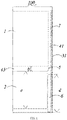
- FIG. 1 is a structural schematic diagram of a refrigerator according to the present invention.
- the present invention provides a refrigerator 100.
- the refrigerator 100 has a cabinet and a door body openably and closably disposed on the cabinet.
- the cabinet comprises a housing, a refrigerating inner liner 1 and a freezing inner liner 2 arranged in the housing, and a foaming layer formed between the housing, the freezing inner liner 2 and the refrigerating inner liner 1.
- the refrigerator 100 is placed in a vertical direction, and generally, the freezing inner liner 2 is disposed below, the refrigerating inner liner 1 is disposed above, and the door body is openable toward the front side.
- the "front”, “rear”, “up”, “down” etc. mentioned below all refer to a relative relationship between two parts, rather than a specific position.
- the housing comprises a back plate 31 disposed opposite to the door body and two side plates extending forward from the back plate 31, and the foaming layer comprises a first foaming zone 41 disposed close to the back plate 31 and a second foaming zone disposed close to the side plates, the refrigerating inner liner 1 and the freezing inner liner 2 are spaced apart from each other and a middle beam is formed therebetween, and the foaming layer further comprises a third foaming zone 43 disposed inside the middle beam.
- the refrigerator 100 further comprises a sealing device 5 that at least partially spaces the first foaming zone 41 apart from the third foaming zone 43, so that during the foaming process, the circulation of the foaming material between the first foaming zone 41 and the third foaming zone 43 is hindered.
- the foaming material reaches the first foaming zone 41, only part of the foaming material enters the interior of the middle beam through the first foaming zone 41 or the second foaming zone due to the blocking of the sealing device 5, and a large amount of foaming material will not enter the interior of the middle beam at one time, so that the density of the foaming material in the interior of the middle beam will not be too large, and the density of the foaming material in the first foaming zone 41 and the third foaming zone 43 can reach a uniform status.
- the refrigerator 100 further comprises a conduit 6 for conveying the foaming material.
- the conduit 6 is buried in the first foaming zone 41 and extends from the edge of the back plate 31 toward the third foaming zone 43.
- the sealing device 5 is at least distributed on an extension path of the conduit 6. Since the conduit 6 serves as a device for conveying the foaming material during the foaming process, the density of the foaming material at an opening of the conduit 6 is the largest. Therefore, with the sealing device 5 being disposed on the extension path of the conduit 6, a lot of foaming material may be limited from directly entering the interior of the middle beam, and the filling uniformity of the foaming material can be further improved effectively.
- the thickness of the first foaming zone 41 on the back side of the freezing inner liner 2 is usually thicker than the thickness of the refrigerating inner liner 1.
- a distance between the freezing inner liner 2 and the back plate 31 is also greater than the distance between the refrigerating inner liner 1 and the back plate 31. Therefore, the conduit 6 is usually disposed between the freezing inner liner 2 and the back plate 31, so that the conduit 6 has enough space. Therefore, after the foaming material is discharged from the conduit 6, it is difficult for the foaming material to enter between the refrigerating inner liner 1 and the back plate 31 because the distance between the refrigerating inner liner 1 and the back plate 31 is relatively small.
- the sealing device 5 in the present embodiment may further play a guiding role, guiding the foaming material to enter between the refrigerating inner liner 1 and the back plate 31. Therefore, the conduit 6 is disposed between the freezing inner liner 2 and the back plate and does not extend beyond the sealing device 5 in the extension direction. On the one hand, such an arrangement is intended to guide the foaming material to be filled better, and on the other hand, the conduit 6 is not adapted to be placed between the refrigerating inner liner 1 and the back plate 31 because the gap between the refrigerating inner liner 1 and the back plate 31 is too narrow.
- the housing further comprises a bottom plate and a top plate.
- the conduit 6 extends upward from the bottom plate to the rear of the freezing inner liner 2. Assuming that a length of the freezing inner liner 2 in the vertical direction is a and a length of the conduit 6 in the vertical direction is d, a/2 ⁇ d ⁇ a in the present embodiment.
- the refrigerator 100 further comprises a vacuum thermal insulation plate 7 disposed against the back plate 31.
- the sealing device 5 completely spaces the first foaming zone 41 apart from the third foaming zone 43, so that after the foaming material enters the first foaming zone 41, it can only directly enter the second foaming zone and then enter the third foaming zone 43 through the second foaming zone, thereby preventing the accumulation of the foaming material in the third foaming zone 43 in the middle beam and making the density of the foaming material uniform.
- the sealing device 5 does not completely space the first foaming zone 41 apart from the third foaming zone 43, the objective of the present invention can be achieved as long as the sealing device 5 is distributed on the extension path of the conduit 6, and forms a hindrance for the flow of the foaming material into the third foaming zone 43.
- the middle beam is arranged in a transverse direction
- the sealing device 5 is also arranged in the transverse direction and fixed between the freezing inner liner 2 and the refrigerating inner liner 1.
- the sealing device 5 extends arcuately in the longitudinal direction, and, as shown in FIG. 1 , the sealing device 5 protrudes toward the back plate 31. Therefore, a length of the sealing device 5 in the longitudinal direction is larger than a height of the middle beam in the longitudinal direction.
- a height of the middle beam in the longitudinal direction is b and a deployed length of the sealing device 5 in the longitudinal direction is c, b ⁇ c.
- the deployed length of the sealing device 5 in the longitudinal direction should not be too large because a too large deployed length might hinder the flow of the foaming material to the rear side of the refrigerating inner liner 1. Therefore, c ⁇ 3b/2.
- the present invention further provides a manufacturing method of the refrigerator 100, comprising:
- the manufacturing method of the aforementioned refrigerator 100 of the present invention only comprises processes before and after foaming. Specifically, in the manufacturing method of the refrigerator 100 of the present invention, as compared with the prior art, it is necessary to first dispose the sealing device 5 on the rear side of the middle beam, and then fill the material to prevent the foaming material from directly entering from the back plate 31 into the interior of the middle beam. Furthermore, as stated above, in the specific implementation, the step of "disposing a sealing device 5 at a position of a middle beam close to a back plate 31" is specifically: using the sealing device 5 to completely close a side of the middle beam close to the back plate 31.
- the foaming material enters the rear side of the refrigerating inner liner 1 from the conduit 6 from the rear side of the freezing inner liner 2, and on the other hand, spreads from the position close to the back plate 31 to a position close to the side plates, so that the foaming material only might enter the interior of the middle beam from the side plates such that the density of the foaming material in the interior of the middle beam is not too high.
- the present invention provides the refrigerator 100 and a manufacturing method thereof.
- the refrigerator 100 in the present invention is partially provided with the sealing device 5 between the first foaming zone 41 and the third foaming zone 43, so that during the material-filing and foaming process, the foaming material will not directly enter the interior of the middle beam, such that the foaming density in the third foaming zone 43 will not be too high, and the density of the foaming material is made more balanced throughout the foaming process.
Landscapes
- Engineering & Computer Science (AREA)
- Chemical & Material Sciences (AREA)
- Combustion & Propulsion (AREA)
- Physics & Mathematics (AREA)
- Mechanical Engineering (AREA)
- Thermal Sciences (AREA)
- General Engineering & Computer Science (AREA)
- Refrigerator Housings (AREA)
Abstract
Description
- The present invention relates to the field of refrigerators and manufacture thereof, and particularly to a refrigerator with a more uniform foaming layer, and a manufacturing method of the refrigerator.
- Along with the improvement of people's living standards, people have higher and higher requirements for refrigerators. To ensure the thermal insulation, traditional refrigerators usually employ a thick foaming layer which therefore occupies a large area, so that the useable volume in the refrigerators becomes smaller. Therefore, as the thermally insulating materials are further developed, the thermal insulation layer of the refrigerators is further thinned, and a super-thin and large-volume refrigerator arises.
- In the super-thin and large-volume refrigerator, the distance between the inner liner and the housing is narrow, which means a narrow space is left for the foaming layer. Therefore, the flowing and filling of a foaming material is a problem difficult to solve. Currently, a majority of refrigerator manufacturers choose to use a plurality of guns to fill material at a back plate of the refrigerator to minimize a flow path of the foaming material. However, the material filling according to the method requires a high cost and exhibits a low efficiency, and cannot satisfy requirements for quick production of refrigerators.
- Alternatively, one gun may be selected and used to fill material at a bottom steel of the refrigerator. However, during one-gun material filling, the foaming material enters between the inner liner and the housing through a conduit. A freezing inner liner usually needs a thicker foaming layer than a refrigerating inner liner, a foaming layer is also formed in a middle beam between the freezing inner liner and the refrigerating inner liner, and the conduit is usually disposed in the foaming layer on the rear side of the freezing inner liner and extends to the middle beam. Therefore, the density of the foaming layer at the middle beam is usually high. To make the overall foaming layer of the refrigerator have a uniform density, excessive foaming material usually needs to be filled, so that the amount of used foaming layer increases and the cost rises accordingly.
- In order to solve the above problems, the present invention proposes a refrigerator comprising a housing, a refrigerating inner liner and a freezing inner liner arranged in the housing, and a foaming layer formed between the housing, the refrigerating inner liner and the freezing inner liner; the housing comprises a back plate and two side plates extending forward from the back plate, and the foaming layer comprises a first foaming zone disposed close to the back plate and a second foaming zone disposed close to the side plates; the refrigerating inner liner and the freezing inner liner are spaced apart from each other and a middle beam is formed therebetween, the foaming layer further comprises a third foaming zone disposed in an interior of the middle beam, and the third foaming zone is connected to the second foaming zone; the refrigerator further comprises a sealing device that at least partially spaces the first foaming zone apart from the third foaming zone.
- As a further improvement of the present invention, the refrigerator further comprises a conduit for conveying the foaming material, and the conduit is buried in the first foaming zone and extends from an edge of the back plate toward the third foaming zone; the sealing device is at least distributed on an extension path of the conduit.
- As a further improvement of the present invention, the conduit is disposed between the freezing inner liner and the back plate and does not extend beyond the sealing device in the extension direction.
- As a further improvement of the present invention, the sealing device completely spaces the first foaming zone apart from the third foaming zone.
- As a further improvement of the present invention, the middle beam is arranged in a transverse direction, and the sealing device is also arranged in the transverse direction and fixed between the freezing inner liner and the refrigerating inner liner.
- As a further improvement of the present invention, the sealing device extends arcuately in a longitudinal direction.
- As a further improvement of the present invention, a height of the middle beam in the longitudinal direction is b, a deployed length of the sealing device in the longitudinal direction is c, and b<c<3b/2.
- To address the above problem, the present invention provides a manufacturing method of a refrigerator, comprising: disposing a sealing device at a position of a middle beam close to a back plate; extending a conduit between a housing of the refrigerator and a freezing inner liner; confirming that the sealing device is disposed on an extension path of the conduit; connecting an end of the conduit away from an outfeed direction to an injection port; opening an outfeed gun to fill a foaming material into the conduit.
- As a further improvement of the present invention, the step of "disposing a sealing device at a position of a middle beam close to a back plate" is specifically: using the sealing device to completely close a side of the middle beam close to the back plate.
- Advantageous effects of the present invention are as follows: after the foaming material reaches the first foaming zone, only part of the foaming material enters the interior of the middle beam through the first foaming zone or the second foaming zone due to the blocking of the sealing device, and a large amount of foaming material will not enter the interior of the middle beam at one time, so that the density of the foaming material in the interior of the middle beam will not be too large, and the density of the foaming material in the first foaming zone and the third foaming zone can reach a uniform status.
-
FIG. 1 is a structural schematic diagram of a refrigerator according to the present invention. - In order to enable those skilled in the art to better understand technical solutions of the present invention, the technical solutions in the embodiments of the present invention will be clearly and completely described below with reference to figures in the embodiments of the present invention. Obviously, the described embodiments are only partial embodiments of the present invention, rather than all the embodiments. Based on the embodiments of the present invention, all other embodiments obtained by those having ordinary skill in the art without making inventive efforts shall fall within the protection scope of the present invention.
- In addition, references or numerals might be used repeatedly in different embodiments. Such repetitions are only intended to simply and clearly illustrate the present invention and not to mean there is any association between the discussed different embodiments or structures.
- As shown in
FIG. 1 , the present invention provides arefrigerator 100. Generally, therefrigerator 100 has a cabinet and a door body openably and closably disposed on the cabinet. The cabinet comprises a housing, a refrigerating inner liner 1 and a freezinginner liner 2 arranged in the housing, and a foaming layer formed between the housing, the freezinginner liner 2 and the refrigerating inner liner 1. Here, it is agreed that therefrigerator 100 is placed in a vertical direction, and generally, the freezinginner liner 2 is disposed below, the refrigerating inner liner 1 is disposed above, and the door body is openable toward the front side. It should be appreciated that the "front", "rear", "up", "down" etc. mentioned below all refer to a relative relationship between two parts, rather than a specific position. - Specifically, the housing comprises a
back plate 31 disposed opposite to the door body and two side plates extending forward from theback plate 31, and the foaming layer comprises afirst foaming zone 41 disposed close to theback plate 31 and a second foaming zone disposed close to the side plates, the refrigerating inner liner 1 and the freezinginner liner 2 are spaced apart from each other and a middle beam is formed therebetween, and the foaming layer further comprises athird foaming zone 43 disposed inside the middle beam. Since the freezinginner liner 2 and the refrigerating inner liner 1 in therefrigerator 100 are spaced apart from theback plate 31 and the side plates, and the freezinginner liner 2 and the refrigerating inner liner 1 are also spaced apart from each other, the above-mentionedthird foaming zone 43 is connected to the second foaming zone, that is, during the foaming process, the foaming material may circulate between thethird foaming zone 43 and the second foaming zone. In the present invention, therefrigerator 100 further comprises asealing device 5 that at least partially spaces thefirst foaming zone 41 apart from thethird foaming zone 43, so that during the foaming process, the circulation of the foaming material between thefirst foaming zone 41 and thethird foaming zone 43 is hindered. - Therefore, after the foaming material reaches the
first foaming zone 41, only part of the foaming material enters the interior of the middle beam through thefirst foaming zone 41 or the second foaming zone due to the blocking of thesealing device 5, and a large amount of foaming material will not enter the interior of the middle beam at one time, so that the density of the foaming material in the interior of the middle beam will not be too large, and the density of the foaming material in thefirst foaming zone 41 and thethird foaming zone 43 can reach a uniform status. - The
refrigerator 100 further comprises aconduit 6 for conveying the foaming material. Theconduit 6 is buried in thefirst foaming zone 41 and extends from the edge of theback plate 31 toward thethird foaming zone 43. Thesealing device 5 is at least distributed on an extension path of theconduit 6. Since theconduit 6 serves as a device for conveying the foaming material during the foaming process, the density of the foaming material at an opening of theconduit 6 is the largest. Therefore, with thesealing device 5 being disposed on the extension path of theconduit 6, a lot of foaming material may be limited from directly entering the interior of the middle beam, and the filling uniformity of the foaming material can be further improved effectively. - In addition, since the freezing
inner liner 2 generally needs a better heat preservation effect, the thickness of thefirst foaming zone 41 on the back side of the freezinginner liner 2 is usually thicker than the thickness of the refrigerating inner liner 1. Correspondingly, a distance between the freezinginner liner 2 and theback plate 31 is also greater than the distance between the refrigerating inner liner 1 and theback plate 31. Therefore, theconduit 6 is usually disposed between the freezinginner liner 2 and theback plate 31, so that theconduit 6 has enough space. Therefore, after the foaming material is discharged from theconduit 6, it is difficult for the foaming material to enter between the refrigerating inner liner 1 and theback plate 31 because the distance between the refrigerating inner liner 1 and theback plate 31 is relatively small. Therefore, thesealing device 5 in the present embodiment may further play a guiding role, guiding the foaming material to enter between the refrigerating inner liner 1 and theback plate 31. Therefore, theconduit 6 is disposed between the freezinginner liner 2 and the back plate and does not extend beyond thesealing device 5 in the extension direction. On the one hand, such an arrangement is intended to guide the foaming material to be filled better, and on the other hand, theconduit 6 is not adapted to be placed between the refrigerating inner liner 1 and theback plate 31 because the gap between the refrigerating inner liner 1 and theback plate 31 is too narrow. - Certainly, the extension direction of the
conduit 6 should not be too short. The housing further comprises a bottom plate and a top plate. Generally, theconduit 6 extends upward from the bottom plate to the rear of the freezinginner liner 2. Assuming that a length of the freezinginner liner 2 in the vertical direction is a and a length of theconduit 6 in the vertical direction is d, a/2<d ≦ a in the present embodiment. - In addition, there is not only the
first foaming zone 41 between theback plate 31 and the refrigerating inner liner 1 and the freezinginner liner 2. In the present embodiment, therefrigerator 100 further comprises a vacuum thermal insulation plate 7 disposed against theback plate 31. - Specifically, in the present embodiment, the
sealing device 5 completely spaces thefirst foaming zone 41 apart from thethird foaming zone 43, so that after the foaming material enters thefirst foaming zone 41, it can only directly enter the second foaming zone and then enter thethird foaming zone 43 through the second foaming zone, thereby preventing the accumulation of the foaming material in thethird foaming zone 43 in the middle beam and making the density of the foaming material uniform. - Certainly, if the
sealing device 5 does not completely space thefirst foaming zone 41 apart from thethird foaming zone 43, the objective of the present invention can be achieved as long as thesealing device 5 is distributed on the extension path of theconduit 6, and forms a hindrance for the flow of the foaming material into thethird foaming zone 43. - Further, since the freezing
inner liner 2 and the refrigerating inner liner 1 are distributed in the vertical direction, the middle beam is arranged in a transverse direction, and thesealing device 5 is also arranged in the transverse direction and fixed between the freezinginner liner 2 and the refrigerating inner liner 1. Furthermore, thesealing device 5 extends arcuately in the longitudinal direction, and, as shown inFIG. 1 , thesealing device 5 protrudes toward theback plate 31. Therefore, a length of thesealing device 5 in the longitudinal direction is larger than a height of the middle beam in the longitudinal direction. Specifically, assuming a height of the middle beam in the longitudinal direction is b and a deployed length of thesealing device 5 in the longitudinal direction is c, b<c. Certainly, the deployed length of thesealing device 5 in the longitudinal direction should not be too large because a too large deployed length might hinder the flow of the foaming material to the rear side of the refrigerating inner liner 1. Therefore, c<3b/2. - Correspondingly, the present invention further provides a manufacturing method of the
refrigerator 100, comprising: - disposing a
sealing device 5 at a position of a middle beam close to aback plate 31; - extending a
conduit 6 between a housing of therefrigerator 100 and a freezinginner liner 2; - confirming that the
sealing device 5 is disposed in an outfeed direction of theconduit 6; - connecting an end of the conduit away from the outfeed direction to an injection port;
- opening an outfeed gun to fill the foaming material into the
conduit 6. - The manufacturing method of the
aforementioned refrigerator 100 of the present invention only comprises processes before and after foaming. Specifically, in the manufacturing method of therefrigerator 100 of the present invention, as compared with the prior art, it is necessary to first dispose thesealing device 5 on the rear side of the middle beam, and then fill the material to prevent the foaming material from directly entering from theback plate 31 into the interior of the middle beam. Furthermore, as stated above, in the specific implementation, the step of "disposing asealing device 5 at a position of a middle beam close to aback plate 31" is specifically: using thesealing device 5 to completely close a side of the middle beam close to theback plate 31. Therefore, during the material-filling and foaming process of therefrigerator 100, the foaming material, on the one hand, enters the rear side of the refrigerating inner liner 1 from theconduit 6 from the rear side of the freezinginner liner 2, and on the other hand, spreads from the position close to theback plate 31 to a position close to the side plates, so that the foaming material only might enter the interior of the middle beam from the side plates such that the density of the foaming material in the interior of the middle beam is not too high. - Therefore, in summary, the present invention provides the
refrigerator 100 and a manufacturing method thereof. Therefrigerator 100 in the present invention is partially provided with thesealing device 5 between thefirst foaming zone 41 and thethird foaming zone 43, so that during the material-filing and foaming process, the foaming material will not directly enter the interior of the middle beam, such that the foaming density in thethird foaming zone 43 will not be too high, and the density of the foaming material is made more balanced throughout the foaming process. - It should be understood that although the description is described according to the embodiments, not every embodiment only comprises one independent technical solution, that such a description manner is only for the sake of clarity, that those skilled in the art should take the description as an integral part, and that the technical solutions in the embodiments may be suitably combined to form other embodiments understandable by those skilled in the art.
- The detailed descriptions set forth above are merely specific illustrations of feasible embodiments of the present invention, and are not intended to limit the scope of protection of the present invention. All equivalent embodiments or modifications that do not depart from the art spirit of the present invention should fall within the scope of protection of the present invention.
Claims (9)
- A refrigerator, wherein the refrigerator comprises a housing, a refrigerating inner liner and a freezing inner liner arranged in the housing, and a foaming layer formed between the housing, the refrigerating inner liner and the freezing inner liner; the housing comprises a back plate and two side plates extending forward from the back plate, and the foaming layer comprises a first foaming zone disposed close to the back plate and a second foaming zone disposed close to the side plates; the refrigerating inner liner and the freezing inner liner are spaced apart from each other and a middle beam is formed therebetween, the foaming layer further comprises a third foaming zone disposed in an interior of the middle beam, and the third foaming zone is connected to the second foaming zone; the refrigerator further comprises a sealing device that at least partially spaces the first foaming zone apart from the third foaming zone.
- The refrigerator according to claim 1, wherein the refrigerator further comprises a conduit for conveying the foaming material, and the conduit is buried in the first foaming zone and extends from an edge of the back plate toward the third foaming zone; the sealing device is at least distributed on an extension path of the conduit.
- The refrigerator according to claim 2, wherein the conduit is disposed between the freezing inner liner and the back plate and does not extend beyond the sealing device in the extension direction.
- The refrigerator according to claim 1, wherein the sealing device completely spaces the first foaming zone apart from the third foaming zone.
- The refrigerator according to claim 1, wherein the middle beam is arranged in a transverse direction, and the sealing device is also arranged in the transverse direction and fixed between the freezing inner liner and the refrigerating inner liner.
- The refrigerator according to claim 5, wherein the sealing device extends arcuately in a longitudinal direction.
- The refrigerator according to claim 6, wherein a height of the middle beam in the longitudinal direction is b, a deployed length of the sealing device in the longitudinal direction is c, and b<c<3b/2.
- A manufacturing method of a refrigerator, wherein the method comprises:disposing a sealing device at a position of a middle beam close to a back plate;extending a conduit between a housing of the refrigerator and a freezing inner liner;confirming that the sealing device is disposed on an extension path of the conduit;connecting an end of the conduit away from an outfeed direction to an injection port;opening an outfeed gun to fill a foaming material into the conduit.
- The refrigerator according to claim 8, wherein the step of "disposing a sealing device at a position of a middle beam close to a back plate" is specifically:
using the sealing device to completely close a side of the middle beam close to the back plate.
Applications Claiming Priority (2)
| Application Number | Priority Date | Filing Date | Title |
|---|---|---|---|
| CN201910440474.0A CN111981750B (en) | 2019-05-24 | 2019-05-24 | Refrigerator and method of manufacturing the same |
| PCT/CN2019/111182 WO2020237969A1 (en) | 2019-05-24 | 2019-10-15 | Refrigerator and method for manufacturing same |
Publications (3)
| Publication Number | Publication Date |
|---|---|
| EP3978848A1 true EP3978848A1 (en) | 2022-04-06 |
| EP3978848A4 EP3978848A4 (en) | 2022-07-13 |
| EP3978848B1 EP3978848B1 (en) | 2023-11-22 |
Family
ID=73436715
Family Applications (1)
| Application Number | Title | Priority Date | Filing Date |
|---|---|---|---|
| EP19930317.3A Active EP3978848B1 (en) | 2019-05-24 | 2019-10-15 | Refrigerator and method for manufacturing same |
Country Status (4)
| Country | Link |
|---|---|
| US (1) | US20220325941A1 (en) |
| EP (1) | EP3978848B1 (en) |
| CN (1) | CN111981750B (en) |
| WO (1) | WO2020237969A1 (en) |
Families Citing this family (4)
| Publication number | Priority date | Publication date | Assignee | Title |
|---|---|---|---|---|
| CN114688820A (en) * | 2020-12-29 | 2022-07-01 | 广州美的华凌冰箱有限公司 | Refrigeration box and refrigeration equipment |
| CN115371337B (en) * | 2021-05-18 | 2024-12-17 | 合肥美的电冰箱有限公司 | Air duct assembly, box body frame and foaming method of refrigerator |
| CN116067073A (en) * | 2021-11-03 | 2023-05-05 | 青岛海尔电冰箱有限公司 | refrigeration equipment |
| CN116792995A (en) * | 2022-03-14 | 2023-09-22 | 青岛海尔电冰箱有限公司 | Refrigerating apparatus |
Family Cites Families (22)
| Publication number | Priority date | Publication date | Assignee | Title |
|---|---|---|---|---|
| JPS6082192U (en) * | 1983-11-11 | 1985-06-07 | 株式会社富士通ゼネラル | refrigerator |
| IT1173995B (en) * | 1984-05-18 | 1987-06-24 | Eurodomestici Ind Riunite | REFRIGERANT APPLIANCE FURNITURE WITH AT LEAST TWO STORAGE COMPARTMENTS AND WITH INSULATION IN EXPANDED SYNTHETIC MATERIAL |
| US5033636A (en) * | 1988-10-07 | 1991-07-23 | General Electric Company | Refrigerator cabinet liner having non-crinkled corners |
| JPH0682153A (en) * | 1992-09-03 | 1994-03-22 | Toshiba Corp | Thermal insulating box |
| IT1286046B1 (en) * | 1996-10-25 | 1998-07-07 | Whirlpool Europ S R L | INSULATED BODY, FOR EXAMPLE WITH EXPANDED POLYURETHANE OR SIMILAR, SUCH AS A REFRIGERATOR, WITH A PLURALITY OF COMPARTMENTS |
| KR100415822B1 (en) * | 2001-07-26 | 2004-01-24 | 삼성전자주식회사 | Refrigerator |
| CA2383905C (en) * | 2002-04-29 | 2007-06-26 | Camco Inc. | Refrigerator cabinet refrigerant tube assembly |
| DE102008040598A1 (en) * | 2008-07-22 | 2010-01-28 | BSH Bosch und Siemens Hausgeräte GmbH | Method for foaming a hollow body |
| CN101474842B (en) * | 2009-01-24 | 2010-10-06 | 南京红宝丽股份有限公司 | Method for improving filling property of rigid polyurethane foam plastics |
| CN201941120U (en) * | 2010-12-01 | 2011-08-24 | 海信(北京)电器有限公司 | Box and refrigerator box both provided with foaming exhaust auxiliary structure |
| JP5506733B2 (en) * | 2011-04-15 | 2014-05-28 | 三菱電機株式会社 | refrigerator |
| US8128992B1 (en) * | 2011-04-18 | 2012-03-06 | General Electric Company | Method for insulating an appliance with an expanding insulating material |
| US8678530B2 (en) * | 2011-04-25 | 2014-03-25 | General Electric Company | Foam manifold for injection molding consumer appliance case, foamed-in case, and related method |
| KR20140009647A (en) * | 2012-07-12 | 2014-01-23 | 삼성전자주식회사 | Refrigerator and manufacturing method |
| CN102997539B (en) * | 2012-12-17 | 2015-02-25 | 合肥华凌股份有限公司 | Refrigerator and method of manufacturing the same |
| KR20150010846A (en) * | 2013-07-18 | 2015-01-29 | 삼성전자주식회사 | Refrigerator |
| US9574819B2 (en) * | 2014-01-07 | 2017-02-21 | Samsung Electronics Co., Ltd. | Refrigerator |
| US9970701B2 (en) * | 2014-01-07 | 2018-05-15 | Samsung Electronics Co., Ltd. | Refrigerator having a heating pipe |
| KR102442071B1 (en) * | 2015-10-19 | 2022-09-13 | 삼성전자주식회사 | Refrigerator and its manufacturing method |
| KR102338097B1 (en) * | 2017-03-28 | 2021-12-10 | 엘지전자 주식회사 | insulating material injection guide for refrigerator and injection method using thereof |
| CN108357048B (en) * | 2018-02-08 | 2020-04-17 | 合肥华凌股份有限公司 | Preparation method of box body, box body for refrigeration equipment and refrigeration equipment |
| CN109708387A (en) * | 2018-10-17 | 2019-05-03 | 青岛海尔股份有限公司 | A kind of refrigerator and its manufacturing method |
-
2019
- 2019-05-24 CN CN201910440474.0A patent/CN111981750B/en active Active
- 2019-10-15 US US17/613,938 patent/US20220325941A1/en not_active Abandoned
- 2019-10-15 WO PCT/CN2019/111182 patent/WO2020237969A1/en not_active Ceased
- 2019-10-15 EP EP19930317.3A patent/EP3978848B1/en active Active
Also Published As
| Publication number | Publication date |
|---|---|
| US20220325941A1 (en) | 2022-10-13 |
| CN111981750B (en) | 2021-11-26 |
| EP3978848A4 (en) | 2022-07-13 |
| WO2020237969A1 (en) | 2020-12-03 |
| CN111981750A (en) | 2020-11-24 |
| EP3978848B1 (en) | 2023-11-22 |
Similar Documents
| Publication | Publication Date | Title |
|---|---|---|
| EP3978848A1 (en) | Refrigerator and method for manufacturing same | |
| EP3647695A1 (en) | Refrigerator | |
| JP6655277B2 (en) | refrigerator | |
| TWI401404B (en) | Refrigerator | |
| WO2014024601A1 (en) | Heat insulating box, and refrigerator with heat insulating box | |
| JP6955587B2 (en) | refrigerator | |
| US11333420B2 (en) | Refrigerator preventing condensation in a divided portion of a housing body thereof | |
| US11262120B2 (en) | Refrigeration appliance and door body thereof | |
| JP2004125394A (en) | Refrigerator | |
| EP2789947B1 (en) | Refrigerator | |
| JP6200742B2 (en) | refrigerator | |
| KR101260559B1 (en) | Refrigerator | |
| JP2009092368A (en) | refrigerator | |
| JP7569572B2 (en) | refrigerator | |
| CN220017822U (en) | refrigerator | |
| CN206695483U (en) | The middle beam assembly and refrigerator of a kind of refrigerator | |
| CN220567593U (en) | Refrigerating apparatus | |
| JP2019039665A (en) | refrigerator | |
| CN112923627B (en) | Refrigerator with a door | |
| JP6402352B2 (en) | refrigerator | |
| CN209801891U (en) | Flat plate aluminum heat pipe fixing device and refrigerating box | |
| JP2020085300A (en) | refrigerator | |
| CN118705795A (en) | refrigerator | |
| US20220235998A1 (en) | Refrigerator and manufacturing method thereof | |
| WO2026067667A1 (en) | Energy storage cabinet and electric device |
Legal Events
| Date | Code | Title | Description |
|---|---|---|---|
| STAA | Information on the status of an ep patent application or granted ep patent |
Free format text: STATUS: THE INTERNATIONAL PUBLICATION HAS BEEN MADE |
|
| PUAI | Public reference made under article 153(3) epc to a published international application that has entered the european phase |
Free format text: ORIGINAL CODE: 0009012 |
|
| STAA | Information on the status of an ep patent application or granted ep patent |
Free format text: STATUS: REQUEST FOR EXAMINATION WAS MADE |
|
| 17P | Request for examination filed |
Effective date: 20211222 |
|
| AK | Designated contracting states |
Kind code of ref document: A1 Designated state(s): AL AT BE BG CH CY CZ DE DK EE ES FI FR GB GR HR HU IE IS IT LI LT LU LV MC MK MT NL NO PL PT RO RS SE SI SK SM TR |
|
| REG | Reference to a national code |
Ref country code: DE Ipc: F25D0023060000 Ref country code: DE Ref legal event code: R079 Ref document number: 602019042139 Country of ref document: DE Free format text: PREVIOUS MAIN CLASS: F25D0023080000 Ipc: F25D0023060000 |
|
| A4 | Supplementary search report drawn up and despatched |
Effective date: 20220613 |
|
| RIC1 | Information provided on ipc code assigned before grant |
Ipc: B29C 44/18 20060101ALI20220608BHEP Ipc: F25D 23/00 20060101ALI20220608BHEP Ipc: F25D 23/08 20060101ALI20220608BHEP Ipc: F25D 23/06 20060101AFI20220608BHEP |
|
| DAV | Request for validation of the european patent (deleted) | ||
| DAX | Request for extension of the european patent (deleted) | ||
| GRAJ | Information related to disapproval of communication of intention to grant by the applicant or resumption of examination proceedings by the epo deleted |
Free format text: ORIGINAL CODE: EPIDOSDIGR1 |
|
| STAA | Information on the status of an ep patent application or granted ep patent |
Free format text: STATUS: GRANT OF PATENT IS INTENDED |
|
| GRAP | Despatch of communication of intention to grant a patent |
Free format text: ORIGINAL CODE: EPIDOSNIGR1 |
|
| INTG | Intention to grant announced |
Effective date: 20230619 |
|
| GRAS | Grant fee paid |
Free format text: ORIGINAL CODE: EPIDOSNIGR3 |
|
| GRAA | (expected) grant |
Free format text: ORIGINAL CODE: 0009210 |
|
| STAA | Information on the status of an ep patent application or granted ep patent |
Free format text: STATUS: THE PATENT HAS BEEN GRANTED |
|
| AK | Designated contracting states |
Kind code of ref document: B1 Designated state(s): AL AT BE BG CH CY CZ DE DK EE ES FI FR GB GR HR HU IE IS IT LI LT LU LV MC MK MT NL NO PL PT RO RS SE SI SK SM TR |
|
| REG | Reference to a national code |
Ref country code: GB Ref legal event code: FG4D |
|
| REG | Reference to a national code |
Ref country code: CH Ref legal event code: EP Ref country code: DE Ref legal event code: R096 Ref document number: 602019042139 Country of ref document: DE |
|
| REG | Reference to a national code |
Ref country code: IE Ref legal event code: FG4D |
|
| REG | Reference to a national code |
Ref country code: LT Ref legal event code: MG9D |
|
| REG | Reference to a national code |
Ref country code: NL Ref legal event code: MP Effective date: 20231122 |
|
| PG25 | Lapsed in a contracting state [announced via postgrant information from national office to epo] |
Ref country code: GR Free format text: LAPSE BECAUSE OF FAILURE TO SUBMIT A TRANSLATION OF THE DESCRIPTION OR TO PAY THE FEE WITHIN THE PRESCRIBED TIME-LIMIT Effective date: 20240223 |
|
| PG25 | Lapsed in a contracting state [announced via postgrant information from national office to epo] |
Ref country code: IS Free format text: LAPSE BECAUSE OF FAILURE TO SUBMIT A TRANSLATION OF THE DESCRIPTION OR TO PAY THE FEE WITHIN THE PRESCRIBED TIME-LIMIT Effective date: 20240322 |
|
| PG25 | Lapsed in a contracting state [announced via postgrant information from national office to epo] |
Ref country code: LT Free format text: LAPSE BECAUSE OF FAILURE TO SUBMIT A TRANSLATION OF THE DESCRIPTION OR TO PAY THE FEE WITHIN THE PRESCRIBED TIME-LIMIT Effective date: 20231122 |
|
| REG | Reference to a national code |
Ref country code: AT Ref legal event code: MK05 Ref document number: 1634200 Country of ref document: AT Kind code of ref document: T Effective date: 20231122 |
|
| PG25 | Lapsed in a contracting state [announced via postgrant information from national office to epo] |
Ref country code: NL Free format text: LAPSE BECAUSE OF FAILURE TO SUBMIT A TRANSLATION OF THE DESCRIPTION OR TO PAY THE FEE WITHIN THE PRESCRIBED TIME-LIMIT Effective date: 20231122 |
|
| PG25 | Lapsed in a contracting state [announced via postgrant information from national office to epo] |
Ref country code: AT Free format text: LAPSE BECAUSE OF FAILURE TO SUBMIT A TRANSLATION OF THE DESCRIPTION OR TO PAY THE FEE WITHIN THE PRESCRIBED TIME-LIMIT Effective date: 20231122 |
|
| PG25 | Lapsed in a contracting state [announced via postgrant information from national office to epo] |
Ref country code: ES Free format text: LAPSE BECAUSE OF FAILURE TO SUBMIT A TRANSLATION OF THE DESCRIPTION OR TO PAY THE FEE WITHIN THE PRESCRIBED TIME-LIMIT Effective date: 20231122 |
|
| PG25 | Lapsed in a contracting state [announced via postgrant information from national office to epo] |
Ref country code: NL Free format text: LAPSE BECAUSE OF FAILURE TO SUBMIT A TRANSLATION OF THE DESCRIPTION OR TO PAY THE FEE WITHIN THE PRESCRIBED TIME-LIMIT Effective date: 20231122 Ref country code: LT Free format text: LAPSE BECAUSE OF FAILURE TO SUBMIT A TRANSLATION OF THE DESCRIPTION OR TO PAY THE FEE WITHIN THE PRESCRIBED TIME-LIMIT Effective date: 20231122 Ref country code: IS Free format text: LAPSE BECAUSE OF FAILURE TO SUBMIT A TRANSLATION OF THE DESCRIPTION OR TO PAY THE FEE WITHIN THE PRESCRIBED TIME-LIMIT Effective date: 20240322 Ref country code: GR Free format text: LAPSE BECAUSE OF FAILURE TO SUBMIT A TRANSLATION OF THE DESCRIPTION OR TO PAY THE FEE WITHIN THE PRESCRIBED TIME-LIMIT Effective date: 20240223 Ref country code: ES Free format text: LAPSE BECAUSE OF FAILURE TO SUBMIT A TRANSLATION OF THE DESCRIPTION OR TO PAY THE FEE WITHIN THE PRESCRIBED TIME-LIMIT Effective date: 20231122 Ref country code: BG Free format text: LAPSE BECAUSE OF FAILURE TO SUBMIT A TRANSLATION OF THE DESCRIPTION OR TO PAY THE FEE WITHIN THE PRESCRIBED TIME-LIMIT Effective date: 20240222 Ref country code: AT Free format text: LAPSE BECAUSE OF FAILURE TO SUBMIT A TRANSLATION OF THE DESCRIPTION OR TO PAY THE FEE WITHIN THE PRESCRIBED TIME-LIMIT Effective date: 20231122 Ref country code: PT Free format text: LAPSE BECAUSE OF FAILURE TO SUBMIT A TRANSLATION OF THE DESCRIPTION OR TO PAY THE FEE WITHIN THE PRESCRIBED TIME-LIMIT Effective date: 20240322 |
|
| PG25 | Lapsed in a contracting state [announced via postgrant information from national office to epo] |
Ref country code: SE Free format text: LAPSE BECAUSE OF FAILURE TO SUBMIT A TRANSLATION OF THE DESCRIPTION OR TO PAY THE FEE WITHIN THE PRESCRIBED TIME-LIMIT Effective date: 20231122 Ref country code: RS Free format text: LAPSE BECAUSE OF FAILURE TO SUBMIT A TRANSLATION OF THE DESCRIPTION OR TO PAY THE FEE WITHIN THE PRESCRIBED TIME-LIMIT Effective date: 20231122 Ref country code: PL Free format text: LAPSE BECAUSE OF FAILURE TO SUBMIT A TRANSLATION OF THE DESCRIPTION OR TO PAY THE FEE WITHIN THE PRESCRIBED TIME-LIMIT Effective date: 20231122 Ref country code: NO Free format text: LAPSE BECAUSE OF FAILURE TO SUBMIT A TRANSLATION OF THE DESCRIPTION OR TO PAY THE FEE WITHIN THE PRESCRIBED TIME-LIMIT Effective date: 20240222 Ref country code: LV Free format text: LAPSE BECAUSE OF FAILURE TO SUBMIT A TRANSLATION OF THE DESCRIPTION OR TO PAY THE FEE WITHIN THE PRESCRIBED TIME-LIMIT Effective date: 20231122 Ref country code: HR Free format text: LAPSE BECAUSE OF FAILURE TO SUBMIT A TRANSLATION OF THE DESCRIPTION OR TO PAY THE FEE WITHIN THE PRESCRIBED TIME-LIMIT Effective date: 20231122 |
|
| PG25 | Lapsed in a contracting state [announced via postgrant information from national office to epo] |
Ref country code: DK Free format text: LAPSE BECAUSE OF FAILURE TO SUBMIT A TRANSLATION OF THE DESCRIPTION OR TO PAY THE FEE WITHIN THE PRESCRIBED TIME-LIMIT Effective date: 20231122 |
|
| PG25 | Lapsed in a contracting state [announced via postgrant information from national office to epo] |
Ref country code: CZ Free format text: LAPSE BECAUSE OF FAILURE TO SUBMIT A TRANSLATION OF THE DESCRIPTION OR TO PAY THE FEE WITHIN THE PRESCRIBED TIME-LIMIT Effective date: 20231122 |
|
| PG25 | Lapsed in a contracting state [announced via postgrant information from national office to epo] |
Ref country code: SK Free format text: LAPSE BECAUSE OF FAILURE TO SUBMIT A TRANSLATION OF THE DESCRIPTION OR TO PAY THE FEE WITHIN THE PRESCRIBED TIME-LIMIT Effective date: 20231122 |
|
| PG25 | Lapsed in a contracting state [announced via postgrant information from national office to epo] |
Ref country code: SM Free format text: LAPSE BECAUSE OF FAILURE TO SUBMIT A TRANSLATION OF THE DESCRIPTION OR TO PAY THE FEE WITHIN THE PRESCRIBED TIME-LIMIT Effective date: 20231122 Ref country code: SK Free format text: LAPSE BECAUSE OF FAILURE TO SUBMIT A TRANSLATION OF THE DESCRIPTION OR TO PAY THE FEE WITHIN THE PRESCRIBED TIME-LIMIT Effective date: 20231122 Ref country code: RO Free format text: LAPSE BECAUSE OF FAILURE TO SUBMIT A TRANSLATION OF THE DESCRIPTION OR TO PAY THE FEE WITHIN THE PRESCRIBED TIME-LIMIT Effective date: 20231122 Ref country code: IT Free format text: LAPSE BECAUSE OF FAILURE TO SUBMIT A TRANSLATION OF THE DESCRIPTION OR TO PAY THE FEE WITHIN THE PRESCRIBED TIME-LIMIT Effective date: 20231122 Ref country code: EE Free format text: LAPSE BECAUSE OF FAILURE TO SUBMIT A TRANSLATION OF THE DESCRIPTION OR TO PAY THE FEE WITHIN THE PRESCRIBED TIME-LIMIT Effective date: 20231122 Ref country code: DK Free format text: LAPSE BECAUSE OF FAILURE TO SUBMIT A TRANSLATION OF THE DESCRIPTION OR TO PAY THE FEE WITHIN THE PRESCRIBED TIME-LIMIT Effective date: 20231122 Ref country code: CZ Free format text: LAPSE BECAUSE OF FAILURE TO SUBMIT A TRANSLATION OF THE DESCRIPTION OR TO PAY THE FEE WITHIN THE PRESCRIBED TIME-LIMIT Effective date: 20231122 |
|
| REG | Reference to a national code |
Ref country code: DE Ref legal event code: R097 Ref document number: 602019042139 Country of ref document: DE |
|
| PLBE | No opposition filed within time limit |
Free format text: ORIGINAL CODE: 0009261 |
|
| STAA | Information on the status of an ep patent application or granted ep patent |
Free format text: STATUS: NO OPPOSITION FILED WITHIN TIME LIMIT |
|
| PG25 | Lapsed in a contracting state [announced via postgrant information from national office to epo] |
Ref country code: SI Free format text: LAPSE BECAUSE OF FAILURE TO SUBMIT A TRANSLATION OF THE DESCRIPTION OR TO PAY THE FEE WITHIN THE PRESCRIBED TIME-LIMIT Effective date: 20231122 |
|
| 26N | No opposition filed |
Effective date: 20240823 |
|
| PG25 | Lapsed in a contracting state [announced via postgrant information from national office to epo] |
Ref country code: SI Free format text: LAPSE BECAUSE OF FAILURE TO SUBMIT A TRANSLATION OF THE DESCRIPTION OR TO PAY THE FEE WITHIN THE PRESCRIBED TIME-LIMIT Effective date: 20231122 |
|
| REG | Reference to a national code |
Ref country code: CH Ref legal event code: PL |
|
| PG25 | Lapsed in a contracting state [announced via postgrant information from national office to epo] |
Ref country code: MC Free format text: LAPSE BECAUSE OF FAILURE TO SUBMIT A TRANSLATION OF THE DESCRIPTION OR TO PAY THE FEE WITHIN THE PRESCRIBED TIME-LIMIT Effective date: 20231122 |
|
| PG25 | Lapsed in a contracting state [announced via postgrant information from national office to epo] |
Ref country code: BE Free format text: LAPSE BECAUSE OF NON-PAYMENT OF DUE FEES Effective date: 20241031 Ref country code: LU Free format text: LAPSE BECAUSE OF NON-PAYMENT OF DUE FEES Effective date: 20241015 |
|
| PG25 | Lapsed in a contracting state [announced via postgrant information from national office to epo] |
Ref country code: CH Free format text: LAPSE BECAUSE OF NON-PAYMENT OF DUE FEES Effective date: 20241031 |
|
| REG | Reference to a national code |
Ref country code: BE Ref legal event code: MM Effective date: 20241031 |
|
| PG25 | Lapsed in a contracting state [announced via postgrant information from national office to epo] |
Ref country code: FI Free format text: LAPSE BECAUSE OF FAILURE TO SUBMIT A TRANSLATION OF THE DESCRIPTION OR TO PAY THE FEE WITHIN THE PRESCRIBED TIME-LIMIT Effective date: 20231122 |
|
| PG25 | Lapsed in a contracting state [announced via postgrant information from national office to epo] |
Ref country code: IE Free format text: LAPSE BECAUSE OF NON-PAYMENT OF DUE FEES Effective date: 20241015 |
|
| PGFP | Annual fee paid to national office [announced via postgrant information from national office to epo] |
Ref country code: DE Payment date: 20251015 Year of fee payment: 7 |
|
| PGFP | Annual fee paid to national office [announced via postgrant information from national office to epo] |
Ref country code: GB Payment date: 20251023 Year of fee payment: 7 |
|
| PGFP | Annual fee paid to national office [announced via postgrant information from national office to epo] |
Ref country code: FR Payment date: 20251027 Year of fee payment: 7 |
|
| PG25 | Lapsed in a contracting state [announced via postgrant information from national office to epo] |
Ref country code: CY Free format text: LAPSE BECAUSE OF FAILURE TO SUBMIT A TRANSLATION OF THE DESCRIPTION OR TO PAY THE FEE WITHIN THE PRESCRIBED TIME-LIMIT; INVALID AB INITIO Effective date: 20191015 |
|
| PG25 | Lapsed in a contracting state [announced via postgrant information from national office to epo] |
Ref country code: HU Free format text: LAPSE BECAUSE OF FAILURE TO SUBMIT A TRANSLATION OF THE DESCRIPTION OR TO PAY THE FEE WITHIN THE PRESCRIBED TIME-LIMIT; INVALID AB INITIO Effective date: 20191015 |