EP3978822A1 - Air conditioning device - Google Patents
Air conditioning device Download PDFInfo
- Publication number
- EP3978822A1 EP3978822A1 EP19930607.7A EP19930607A EP3978822A1 EP 3978822 A1 EP3978822 A1 EP 3978822A1 EP 19930607 A EP19930607 A EP 19930607A EP 3978822 A1 EP3978822 A1 EP 3978822A1
- Authority
- EP
- European Patent Office
- Prior art keywords
- air
- valve
- conditioning apparatus
- distal end
- refrigerant pipes
- Prior art date
- Legal status (The legal status is an assumption and is not a legal conclusion. Google has not performed a legal analysis and makes no representation as to the accuracy of the status listed.)
- Granted
Links
Images



Classifications
-
- F—MECHANICAL ENGINEERING; LIGHTING; HEATING; WEAPONS; BLASTING
- F24—HEATING; RANGES; VENTILATING
- F24F—AIR-CONDITIONING; AIR-HUMIDIFICATION; VENTILATION; USE OF AIR CURRENTS FOR SCREENING
- F24F3/00—Air-conditioning systems in which conditioned primary air is supplied from one or more central stations to distributing units in the rooms or spaces where it may receive secondary treatment; Apparatus specially designed for such systems
- F24F3/06—Air-conditioning systems in which conditioned primary air is supplied from one or more central stations to distributing units in the rooms or spaces where it may receive secondary treatment; Apparatus specially designed for such systems characterised by the arrangements for the supply of heat-exchange fluid for the subsequent treatment of primary air in the room units
- F24F3/065—Air-conditioning systems in which conditioned primary air is supplied from one or more central stations to distributing units in the rooms or spaces where it may receive secondary treatment; Apparatus specially designed for such systems characterised by the arrangements for the supply of heat-exchange fluid for the subsequent treatment of primary air in the room units with a plurality of evaporators or condensers
-
- F—MECHANICAL ENGINEERING; LIGHTING; HEATING; WEAPONS; BLASTING
- F25—REFRIGERATION OR COOLING; COMBINED HEATING AND REFRIGERATION SYSTEMS; HEAT PUMP SYSTEMS; MANUFACTURE OR STORAGE OF ICE; LIQUEFACTION SOLIDIFICATION OF GASES
- F25B—REFRIGERATION MACHINES, PLANTS OR SYSTEMS; COMBINED HEATING AND REFRIGERATION SYSTEMS; HEAT PUMP SYSTEMS
- F25B41/00—Fluid-circulation arrangements
- F25B41/20—Disposition of valves, e.g. of on-off valves or flow control valves
-
- F—MECHANICAL ENGINEERING; LIGHTING; HEATING; WEAPONS; BLASTING
- F24—HEATING; RANGES; VENTILATING
- F24F—AIR-CONDITIONING; AIR-HUMIDIFICATION; VENTILATION; USE OF AIR CURRENTS FOR SCREENING
- F24F1/00—Room units for air-conditioning, e.g. separate or self-contained units or units receiving primary air from a central station
- F24F1/06—Separate outdoor units, e.g. outdoor unit to be linked to a separate room comprising a compressor and a heat exchanger
- F24F1/26—Refrigerant piping
- F24F1/32—Refrigerant piping for connecting the separate outdoor units to indoor units
-
- F—MECHANICAL ENGINEERING; LIGHTING; HEATING; WEAPONS; BLASTING
- F25—REFRIGERATION OR COOLING; COMBINED HEATING AND REFRIGERATION SYSTEMS; HEAT PUMP SYSTEMS; MANUFACTURE OR STORAGE OF ICE; LIQUEFACTION SOLIDIFICATION OF GASES
- F25B—REFRIGERATION MACHINES, PLANTS OR SYSTEMS; COMBINED HEATING AND REFRIGERATION SYSTEMS; HEAT PUMP SYSTEMS
- F25B13/00—Compression machines, plants or systems, with reversible cycle
-
- F—MECHANICAL ENGINEERING; LIGHTING; HEATING; WEAPONS; BLASTING
- F25—REFRIGERATION OR COOLING; COMBINED HEATING AND REFRIGERATION SYSTEMS; HEAT PUMP SYSTEMS; MANUFACTURE OR STORAGE OF ICE; LIQUEFACTION SOLIDIFICATION OF GASES
- F25B—REFRIGERATION MACHINES, PLANTS OR SYSTEMS; COMBINED HEATING AND REFRIGERATION SYSTEMS; HEAT PUMP SYSTEMS
- F25B41/00—Fluid-circulation arrangements
- F25B41/20—Disposition of valves, e.g. of on-off valves or flow control valves
- F25B41/24—Arrangement of shut-off valves for disconnecting a part of the refrigerant cycle, e.g. an outdoor part
-
- F—MECHANICAL ENGINEERING; LIGHTING; HEATING; WEAPONS; BLASTING
- F25—REFRIGERATION OR COOLING; COMBINED HEATING AND REFRIGERATION SYSTEMS; HEAT PUMP SYSTEMS; MANUFACTURE OR STORAGE OF ICE; LIQUEFACTION SOLIDIFICATION OF GASES
- F25B—REFRIGERATION MACHINES, PLANTS OR SYSTEMS; COMBINED HEATING AND REFRIGERATION SYSTEMS; HEAT PUMP SYSTEMS
- F25B41/00—Fluid-circulation arrangements
- F25B41/40—Fluid line arrangements
-
- F—MECHANICAL ENGINEERING; LIGHTING; HEATING; WEAPONS; BLASTING
- F25—REFRIGERATION OR COOLING; COMBINED HEATING AND REFRIGERATION SYSTEMS; HEAT PUMP SYSTEMS; MANUFACTURE OR STORAGE OF ICE; LIQUEFACTION SOLIDIFICATION OF GASES
- F25B—REFRIGERATION MACHINES, PLANTS OR SYSTEMS; COMBINED HEATING AND REFRIGERATION SYSTEMS; HEAT PUMP SYSTEMS
- F25B5/00—Compression machines, plants or systems, with several evaporator circuits, e.g. for varying refrigerating capacity
- F25B5/02—Compression machines, plants or systems, with several evaporator circuits, e.g. for varying refrigerating capacity arranged in parallel
-
- F—MECHANICAL ENGINEERING; LIGHTING; HEATING; WEAPONS; BLASTING
- F25—REFRIGERATION OR COOLING; COMBINED HEATING AND REFRIGERATION SYSTEMS; HEAT PUMP SYSTEMS; MANUFACTURE OR STORAGE OF ICE; LIQUEFACTION SOLIDIFICATION OF GASES
- F25B—REFRIGERATION MACHINES, PLANTS OR SYSTEMS; COMBINED HEATING AND REFRIGERATION SYSTEMS; HEAT PUMP SYSTEMS
- F25B2313/00—Compression machines, plants or systems with reversible cycle not otherwise provided for
- F25B2313/023—Compression machines, plants or systems with reversible cycle not otherwise provided for using multiple indoor units
- F25B2313/0233—Compression machines, plants or systems with reversible cycle not otherwise provided for using multiple indoor units in parallel arrangements
Definitions
- the present disclosure relates to an air-conditioning apparatus in which an outdoor unit installed outdoors and an indoor unit installed indoors are connected by refrigerant pipes to form a refrigerant circuit.
- an outdoor unit is installed outdoors, and an indoor unit or units are installed indoors.
- refrigerant that circulates in a refrigerant circuit transfers heat to air supplied to a heat exchanger in the indoor unit, thereby heating the air, and the heated air is sent to an air-conditioned space; and in a cooling operation, the refrigerant that circulates in the refrigerant circuit receives heat from air supplied to the heat exchanger of the indoor unit, thereby cooling the air, and the cooled air is sent to the air-conditioned space (for example, see Patent Literature 1).
- Such an air-conditioning apparatus as descried above is designed such that the load of components to be selected is equal to the load of a building. It should be noted that the loads are calculated such that an air-conditioning performance in the heating operation or the cooling operation varies from one region to another.
- Patent Literature 1 Japanese Unexamined Patent Application Publication No. 2007-10288
- an existing air-conditioning apparatus When an existing air-conditioning apparatus is installed in a building, components are selected such that in each of floors, the load of an indoor space and the load of an indoor unit are equal to each other. However, in some cases, after installation of an air-conditioning apparatus, the load of an indoor space and the load of an indoor unit that are initially designed are not equal to each other. This is because both the loads change due to a changing load such as a person or persons who enter or leave the building, partitions in each of the floors, and for other reasons. In the case where the load of the indoor space is larger than the load of the indoor unit, an air-conditioning performance of the indoor unit that heats or cools the indoor space is insufficient, and thus needs to be enhanced. In the case where the air-conditioning performance needs to be enhanced, it is necessary to carry out a construction work and to stop the air-conditioning apparatus installed in the building. Thus, an additional work is complicated.
- the present disclosure is applied to solve the above problem, and relates to an air-conditioning apparatus that enables a new indoor unit or units to be easily added without stopping the air-conditioning apparatus, after the air-conditioning apparatus is installed in a building.
- an outdoor unit installed in an outdoor space and an indoor unit installed in an indoor space are connected by refrigerant pipes to form a refrigerant circuit.
- One or more pairs of valve kits are provided at the refrigerant pipes by which the outdoor unit and the indoor unit are connected, and allow a pair of additional refrigerant pipes on an inflow side and an outflow side to be connected to one of the one or more pairs of valve kits, the pair of additional refrigerant pipes being additionally provided to enable a new indoor unit to be added after installation of the air-conditioning apparatus.
- the valve kits of the one or more pairs of valve kits have respective distal end portions that are inclined upwards relative to a horizontal direction. The distal end portions each allow an associated one of the additional refrigerant pipe to be connected to the distal end portion.
- the one or more valve kits are provided on the indoor-side refrigerant pipes that connect the outdoor unit and the indoor unit.
- a pair of refrigerant pipes on an inflow side and an outflow side is connectable to one of the one or more pairs of valve kits.
- the pair of refrigerant pipes is additionally provided as additional refrigerant pipes to enable the new indoor unit to be newly added after installation of the air-conditioning apparatus.
- the valve kits of the one or more pairs of valve kits are provided to have respective distal end portion inclined upwards relative to the horizontal direction. Each of the distal end portions allow an associated one of the additional refrigerant pipes to be connected to the distal end portion.
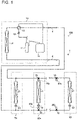
- Fig. 1 is a refrigerant circuit diagram illustrating an air-conditioning apparatus 100 according to Embodiment 1.
- Fig. 2 is an explanatory view illustrating an installed state of the air-conditioning apparatus 100 according to Embodiment 1.
- the air-conditioning apparatus 100 includes a refrigerant circuit 1 that circulates refrigerant.
- a cooling mode or a heating mode can be freely selected as an operation mode of each of indoor units 50.
- the air-conditioning apparatus 100 includes the indoor units 50 and an outdoor unit 10 that is a heat-source unit.
- the outdoor unit 10 and the indoor units 50 are connected by refrigerant pipes 4 to form the refrigerant circuit 1.
- the outdoor unit 10 includes a compressor 11, a backflow prevention device 12, a four-way valve 13, and a heat-source-side heat exchanger 14.
- Each of the indoor units 50 includes a use-side heat exchanger 51 and an expansion device 53.
- the outdoor unit 10 is installed in an outdoor space 200 located outside a building.
- the indoor units 50 are installed in indoor spaces 201 of the building.
- the outdoor space 200 in which the outdoor unit 10 is installed is an outdoor space at a rooftop of the building that is located above the indoor units 50 in an upward direction U.
- the above description concerning the location of the outdoor unit 10, however, is not limiting.
- the outdoor unit 10 may be installed in an outdoor space 200 that is located outside the building and at a position lower than the positions of the indoor units 50.
- components to be provided are selected such that an indoor space load that is the load of an indoor space or spaces and an indoor unit load that is the load of indoor units are equal to each other.
- the indoor space load and the indoor unit load initially designed are not equal to each other. This is because the loads change due to a changing load such as a person or persons who enter or leave the building, partitions in each of the floors, and for other reasons.
- the indoor space load is larger than the indoor unit load
- an air-conditioning performance of the indoor units 50 that heat or cool the indoor space is insufficient.
- comfort of the indoor space is deteriorated. Therefore, one or more pairs of valve kits 60a and 60b as described below are provided in the air-conditioning apparatus 100.
- Fig. 3 is a plan view illustrating the valve kit 60a or 60b in Embodiment 1.
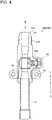
- Fig. 4 is an explanatory diagram illustrating a section of the valve kit 60a or 60b in Embodiment 1 that is taken along line A-A in Fig. 3 .
- Fig. 5 is a top view illustrating the valve kit 60a or 60b in Embodiment 1 as viewed in a direction indicated by an arrow B in Fig. 4 .
- Fig. 6 is a perspective view illustrating the valve kit 60a or 60b in Embodiment 1 and a refrigerant pipe 4a or 4b to be additionally provided.
- one or more pairs of valve kits 60a and 60b are provided at the indoor-side refrigerant pipes 4 that connect the outdoor unit 10 and the indoor units 50, and a pair of refrigerant pipes 4a and refrigerant pipe 4b on an inflow side and an outflow side can be connected to one of the one or more pairs of valve kits 60a and 60b.
- the pair of refrigerant pipes 4a and 4b are additionally provided as additional pipes to enable a new indoor unit 50c to be additionally installed after installation of the air-conditioning apparatus 100. Referring to Fig. 2 , in each of the floors, one pair of valve kits 60a and 60b are provided.
- branch joints 70 are provided in respective middle portions of the indoor-side refrigerant pipes 4 connecting the outdoor unit 10 and the indoor units 50.
- an associated one of the refrigerant pipes 4a and 4b connected to the one or more pairs of valve kits 60a and 60b branches off.
- a refrigerant pipe 4c that extends as a branch pipe from each of the branch joints 70 extends upwards in a vertical direction. Therefore, a portion from each of the refrigerant pipes 4 connecting the outdoor unit 10 and the plurality of indoor units 50 to a distal end portion 61 of an associated one of the valve kits 60a and 60b extends upward in the vertical direction.
- part of the indoor-side refrigerant pipe 4 that extends before reaching the branch joint 70 is made to have a pipe diameter larger than a pipe diameter of each of refrigerant pipes for use in operation that is performed with an air-conditioning performance prior to addition of a new indoor unit or units 50c, in order to enable the air-conditioning performance to be enhanced as the number of new indoor units 50c is increased.
- the refrigerant pipe connected to the valve kit 60a or 60b may be made to branch, without provision of the branch joint 70, from the middle of an associated one of the indoor-side refrigerant pipes 4 connecting the outdoor unit 10 and the indoor units 50.
- each of the valve kits 60a and 60b straightly extends upwards in the vertical direction on an extension above the associated additional refrigerant pipe 4a or 4b that extends upwards from the branch joint 70 in the vertical direction.
- each of the valve kits 60a and 60b extends upwards in the vertical direction over the entire portion thereof from the distal end portion 61 that is be connected to the additional refrigerant pipe 4a or 4b to a downstream side of an operation valve 62. It should be noted that it suffices that each of the valve kits 60a and 60b is inclined upwards to a horizontal direction.
- each of the valve kits 60a and 60b is inclined upwards relative to the horizontal direction.
- An outside diameter of each of the valve kits 60a and 60b is larger than an outside diameter of each of the refrigerant pipes 4a and 4b.
- Each of the valve kits 60a and 60b is a tubular member.
- a flow passage in each of the valve kits 60a and 60b is narrower than a flow passage in each of the refrigerant pipes 4a and 4b.
- each of the valve kits 60a and 60b includes the operation valve 62 and a port 63.
- the operation valve 62 can be opened and closed for refrigerant that flows through the inside of the valve kit 60a or 60b.
- the port 63 is provided closer to the distal end portion 61 than the operation valve 62 in the upward direction U, and is open from the outside to the flow passage.
- a pair of attachment hole portions 64 are provided.
- the attachment hole portions 64 protrude from the body of the valve kit in the horizontal direction and are symmetrical and fixed by fixing members.
- the operation valve 62 has a valve body 62a in the valve kit 60a or 60b.
- the operation valve 62 includes an operation unit 62b that enables the valve body 62a to be rotatably operated from the outside to open/close the flow passage in the valve body 62a.
- the flow passage in the valve body 62a is opened or closed.
- the flow passage in the valve body 62a communicates with the flow passage in the valve kit 60a or 60b on both sides thereof in the vertical direction.
- the port 63 communicates with the outside and the flow passage in the valve kit 60a or 60b in the upward direction U.
- the port 63 is used in evacuation of a refrigerant flow passage formed by an associated one of the additional refrigerant pipes 4a and 4b on the inflow side and the outflow side and the new indoor unit 50c, at the time of adding the new indoor unit 50c.
- a dome-shaped flare 61a is provided at a distal end of the distal end portion 61 of each of the valve kits 60a and 60b in the upward direction U.
- the dome-shaped flare 61a can be jointed to a large-diameter tapered flare 41 that is provided at an end part of the additional refrigerant pipe 4a or 4b in a downward direction D.
- a screw portion 61b is provided on an outer peripheral portion of the distal end portion 61 of each of the valve kits 60a and 60b.
- the screw portion 61b is screwed to a flare nut 42 provided on the additional refrigerant pipe 4a or 4b.
- the screw portion 61b is located below the distal end of the distal end portion 61 that has the shape of the dome-shaped flare 61a in such a manner as to be screwable to the flare nut 42 provided on the additional refrigerant pipe 4a or 4b.
- a nut other than the flare nut 42 may be provided on the additional refrigerant pipe 4a or 4b.
- the refrigerant pipes 4a and 4b on the inflow side and the outflow side that are to be added on a secondary side of one pair of valve kits 60a and 60b and the new indoor unit 50c are connected to refrigerant pipes 4 already provided, using the pair of valve kits 60a and 60b. Furthermore, only the refrigerant flow passage formed by one of the additional refrigerant pipes 4a and 4b on the inflow side and the outflow side and the new indoor unit 50c is evacuated using the port 63. Thereafter, the operation valve 62 is opened, and the new indoor unit 50c is supplied with refrigerant that flows through the refrigerant pipes 4 of the air-conditioning apparatus 100 already installed in the building. By carrying out only such a construction work, it is possible to easily add the new indoor unit 50c, and improve the air-conditioning performance of the air-conditioning apparatus 100 already installed, without stopping the operation of the air-conditioning apparatus 100.
- valve kits 60a and 60b are not provided, and the air-conditioning performance needs to be improved, it is necessary to suspend the operation of the air-conditioning apparatus 100 in order to add the new indoor unit 50c, and to recover all the refrigerant in the air-conditioning apparatus 100.
- the work of additionally installing the new indoor unit is complicated.
- the valve kits 60a and 60b are provided to extend upwards in the vertical direction relative to the refrigerant pipes 4 that connect the outdoor unit 10 and the indoor units 50 before reaching the branch joints 70. Therefore, during the operation of the air-conditioning apparatus 100, refrigerating machine oil that flows through the refrigerant pipes 4 flows downwards in the valve kit 60a or 60b due to gravity, and does not stay in the valve kit 60a or 60b.
- an outdoor unit 10 that is designed to have a capacity margin is previously selected at the timing of installing the air-conditioning apparatus 100. More specifically, the air-conditioning performance of the outdoor unit 10 is enhanced in advance by the number of additional indoor units 50 to be additionally installed, compared with an air-conditioning performance necessary for the number of indoor units 50 at the time of installing the indoor units 50. For example, at the time of installing the air-conditioning apparatus 100 having rated cooling capacity of 28 kW, it is appropriate that the outdoor unit 10 is designed to have a margin of 20 to 30%.
- the diameter of each of electric wires that are connected to the outdoor unit 10 is set larger than that of each of electric wires for use in the air-conditioning performance before a new indoor unit is added.
- An upper limit value is set as a compressor frequency of the outdoor unit 10 or an outdoor fan, based on a basic horsepower. In the case where the air-conditioning performance is enhanced, however, the upper limit value is changed, and an air-conditioning performance required for the indoor space load can be fulfilled. It is appropriate that it is determined whether the air-conditioning performance is enhanced or not, based on, for example, switch setting of the outdoor unit 10 or a total capacity of the indoor units 50 and the new indoor unit 50c, and the upper limit value is automatically changed.
- the outdoor unit 10 installed in the outdoor space 200 and the indoor units 50 installed in the indoor spaces 201 are connected by the refrigerant pipes 4 to form the refrigerant circuit 1.
- the one or more pairs of valve kits 60a and 60b are provided at the refrigerant pipes 4 connecting the outdoor unit 10 and the indoor units 50.
- the pair of refrigerant pipes 4a and 4b on the inflow side and the outflow side are connectable.
- the pair of refrigerant pipes 4a and 4b are additionally provided to enable the new indoor unit 50c to be added after installation of the air-conditioning apparatus 100.
- Each of the valve kits of the one or more pairs of valve kits 60a and 60b is provided such that the distal end portion 61 is inclined upwards relative to the horizontal direction.
- the additional refrigerant pipe 4a or 4b to be additionally provided is connected to each of the distal end portions 61.
- the refrigerating machine oil that is mixed with the refrigerant flowing through the refrigerant pipes 4 of the air-conditioning apparatus 100 already installed in the building and that has specific gravity greater than specific gravity of the refrigerant flows downwards from the valve kit 60a or 60b extending upwards, and does not stay in the valve kit 60a or 60b. Therefore, the refrigerating machine oil does not soil the inside of the valve kit 60a or 60b.
- the refrigerating machine oil does not flow into the new indoor unit 50c from the valve kit 60a or 60b, and needless to say, the new indoor unit 50c is not broken by the refrigerating machine oil. Therefore, the worker can easily perform the work of additionally installing the new indoor unit 50c. That is, it is possible to easily add the new indoor unit 50c without stopping the air-conditioning apparatus 100 already installed in the building.
- each of the valve kits 60a and 60b of the one or more pairs of valve kits 60a and 60b extends upwards in the vertical direction.
- the portion from each of the refrigerant pipes 4 connecting the outdoor unit 10 and the indoor units 50 to an associated one of the distal end portions 61 is inclined upwards relative to the horizontal direction.
- the refrigerating machine oil that is mixed with the refrigerant that flows through the refrigerant pipes 4 of the air-conditioning apparatus 100 already installed in the building and has the specific gravity greater than the specific gravity of the refrigerant flows downwards due to the gravity from the valve kit 60a or 60b that extends upwards or from the refrigerant pipes 4c located below the valve kit 60a or 60b in the downward direction D, and does not stay in the valve kit 60a or 60b. Therefore, the refrigerating machine oil does not soil the inside of the valve kit 60a or 60b.
- the air-conditioning performance of the outdoor unit 10 is previously enhanced by the number of indoor units 50 to be additionally installed, compared with an air-conditioning performance necessary for the number of indoor units 50 at the time of installation thereof.
- the outdoor unit 10 can fulfill the air-conditioning performance without difficulty.
- each of the valve kits 60a and 60b of the one or more pairs of valve kits 60a and 60b includes the operation valve 62 that can be freely opened and closed for the refrigerant that flows through the valve kit 60a or 60b.
- Each of the valve kits 60a and 60b of the one or more pairs of valve kits 60a and 60b also has the port 63 that is provided closer to the distal end portion 61 than the operation valve 62 in the upward direction U, and that is open from the outside to the inside.
- the new indoor unit 50c when being additionally installed, the new indoor unit 50c is first installed along with the additional refrigerant pipes 4a and 4b on the inflow side and the outflow side. Furthermore, only the refrigerant flow passages formed by the additional refrigerant pipes 4a and 4b on the inflow side and the outflow side and the new indoor unit 50c are evacuated using the port 63. Thereafter, the operation valve 62 is opened, and the new indoor unit 50c is supplied with the refrigerant that flows through the refrigerant pipes 4 of the air-conditioning apparatus 100 already installed in the building. Therefore, it is possible to add the new indoor unit 50c without stopping operation of the air-conditioning apparatus 100 already installed in the building.
- the dome-shaped flare 61a is provided at the distal end of each of the distal end portions 61.
- the dome-shaped flare 61a is joinable to the large-diameter tapered flare 41 provided at an end portion of the additional refrigerant pipe 4a or 4b.
- the dome-shaped flare 61a and the large-diameter tapered flare 41 are joined to each other, thereby enabling the new indoor unit 50c to be added.
- the screw portion 61b is provided on the outer peripheral portion of each of the distal end portions 61.
- the screw portion 61b is screwed to the flare nut 42 provided on the additional refrigerant pipe 4a or 4b.
- the screw portion 61b is provided below the distal end of the distal end portion 61 having the shape of the dome-shaped flare 61a, in such a manner as to be screwable to the flare nut 42 provided on the additional refrigerant pipe 4a or 4b.
- the branch joints 70 are provided in the respective middles of the refrigerant pipes 4 that connect the outdoor unit 10 and the indoor units 50. At each of the branch joints 70, an associated one of the refrigerant pipes 4a and 4b connected to the one or more pairs of valve kits 60a and 60b branches off.
- the refrigerant pipe 4c connected to the valve kit 60a or 60b can previously branch off from the refrigerant pipes 4 included in the refrigerant circuit 1.
- refrigerant circuit 4: refrigerant pipe, 4a: refrigerant pipe, 4b: refrigerant pipe, 4c: refrigerant pipe, 10: outdoor unit, 11: compressor, 12: backflow prevention device, 13: four-way valve, 14: heat-source-side heat exchanger, 41: large-diameter tapered flare, 42: flare nut, 50: indoor unit, 50c: new indoor unit, 51: use-side heat exchanger, 53: expansion device, 60a: valve kit, 60b: valve kit, 61: distal end portion, 61a: dome-shaped flare, 61b: screw portion, 62: operation valve, 62a: valve body, 62b: operation portion, 63: port, 64: attachment hole portion, 70: branch joint, 100: air-conditioning apparatus, 200: outdoor space, 201: indoor space
Landscapes
- Engineering & Computer Science (AREA)
- Mechanical Engineering (AREA)
- General Engineering & Computer Science (AREA)
- Physics & Mathematics (AREA)
- Thermal Sciences (AREA)
- Chemical & Material Sciences (AREA)
- Combustion & Propulsion (AREA)
- Other Air-Conditioning Systems (AREA)
- Air Conditioning Control Device (AREA)
- Air Filters, Heat-Exchange Apparatuses, And Housings Of Air-Conditioning Units (AREA)
Abstract
Description
- The present disclosure relates to an air-conditioning apparatus in which an outdoor unit installed outdoors and an indoor unit installed indoors are connected by refrigerant pipes to form a refrigerant circuit.
- In an existing air-conditioning apparatus such as a multi-split air-conditioning apparatus for a building, an outdoor unit is installed outdoors, and an indoor unit or units are installed indoors. In such an air-conditioning apparatus, in a heating operation, refrigerant that circulates in a refrigerant circuit transfers heat to air supplied to a heat exchanger in the indoor unit, thereby heating the air, and the heated air is sent to an air-conditioned space; and in a cooling operation, the refrigerant that circulates in the refrigerant circuit receives heat from air supplied to the heat exchanger of the indoor unit, thereby cooling the air, and the cooled air is sent to the air-conditioned space (for example, see Patent Literature 1).
- Such an air-conditioning apparatus as descried above is designed such that the load of components to be selected is equal to the load of a building. It should be noted that the loads are calculated such that an air-conditioning performance in the heating operation or the cooling operation varies from one region to another.
- Patent Literature 1:
Japanese Unexamined Patent Application Publication No. 2007-10288 - When an existing air-conditioning apparatus is installed in a building, components are selected such that in each of floors, the load of an indoor space and the load of an indoor unit are equal to each other. However, in some cases, after installation of an air-conditioning apparatus, the load of an indoor space and the load of an indoor unit that are initially designed are not equal to each other. This is because both the loads change due to a changing load such as a person or persons who enter or leave the building, partitions in each of the floors, and for other reasons. In the case where the load of the indoor space is larger than the load of the indoor unit, an air-conditioning performance of the indoor unit that heats or cools the indoor space is insufficient, and thus needs to be enhanced. In the case where the air-conditioning performance needs to be enhanced, it is necessary to carry out a construction work and to stop the air-conditioning apparatus installed in the building. Thus, an additional work is complicated.
- The present disclosure is applied to solve the above problem, and relates to an air-conditioning apparatus that enables a new indoor unit or units to be easily added without stopping the air-conditioning apparatus, after the air-conditioning apparatus is installed in a building.
- In an air-conditioning apparatus according to an embodiment of the present disclosure, an outdoor unit installed in an outdoor space and an indoor unit installed in an indoor space are connected by refrigerant pipes to form a refrigerant circuit. One or more pairs of valve kits are provided at the refrigerant pipes by which the outdoor unit and the indoor unit are connected, and allow a pair of additional refrigerant pipes on an inflow side and an outflow side to be connected to one of the one or more pairs of valve kits, the pair of additional refrigerant pipes being additionally provided to enable a new indoor unit to be added after installation of the air-conditioning apparatus. The valve kits of the one or more pairs of valve kits have respective distal end portions that are inclined upwards relative to a horizontal direction. The distal end portions each allow an associated one of the additional refrigerant pipe to be connected to the distal end portion.
- In the air-conditioning apparatus according to the embodiment of the present disclosure, the one or more valve kits are provided on the indoor-side refrigerant pipes that connect the outdoor unit and the indoor unit. A pair of refrigerant pipes on an inflow side and an outflow side is connectable to one of the one or more pairs of valve kits. The pair of refrigerant pipes is additionally provided as additional refrigerant pipes to enable the new indoor unit to be newly added after installation of the air-conditioning apparatus. The valve kits of the one or more pairs of valve kits are provided to have respective distal end portion inclined upwards relative to the horizontal direction. Each of the distal end portions allow an associated one of the additional refrigerant pipes to be connected to the distal end portion. As a result, it is possible to easily add the new indoor unit, using the valve kits, without stopping the air-conditioning apparatus already installed in the building. It is therefore possible to easily add the new indoor unit without stopping the air-conditioning apparatus already installed in the building.
-
- [
Fig. 1] Fig. 1 is a refrigerant circuit diagram illustrating an air-conditioning apparatus according toEmbodiment 1. - [
Fig. 2] Fig. 2 is an explanatory view illustrating an installed state of the air-conditioning apparatus according toEmbodiment 1. - [
Fig. 3] Fig. 3 is a plan view illustrating a valve kit inEmbodiment 1. - [
Fig. 4] Fig. 4 is an explanatory view illustrating a section of the valve kit inEmbodiment 1 that is taken along line A-A inFig. 3 . - [
Fig. 5] Fig. 5 is a top view illustrating the valve kit inEmbodiment 1 as viewed in a direction indicated by an arrow B inFig. 4 . - [
Fig. 6] Fig. 6 is a perspective view illustrating the valve kit inEmbodiment 1 and a refrigerant pipe to be additionally provided. - An embodiment of the present disclosure will be described below with reference to drawings. It should be noted that in each of figures in the drawings, components that are the same as or equivalent to a previous figure or figures are denoted by the same reference signs, and the same is true of the entire text of the present specification. Furthermore, in a sectional view, hatching is omitted as appropriate in view of visibility. In the entire text of the specification, configurations of components are descried as examples, and these descriptions are not limiting.
-
Fig. 1 is a refrigerant circuit diagram illustrating an air-conditioning apparatus 100 according toEmbodiment 1.Fig. 2 is an explanatory view illustrating an installed state of the air-conditioning apparatus 100 according toEmbodiment 1. As illustrated inFigs. 1 and2 , the air-conditioning apparatus 100 includes arefrigerant circuit 1 that circulates refrigerant. In the air-conditioning apparatus 100, a cooling mode or a heating mode can be freely selected as an operation mode of each ofindoor units 50. - The air-
conditioning apparatus 100 includes theindoor units 50 and anoutdoor unit 10 that is a heat-source unit. Theoutdoor unit 10 and theindoor units 50 are connected byrefrigerant pipes 4 to form therefrigerant circuit 1. Theoutdoor unit 10 includes a compressor 11, abackflow prevention device 12, a four-way valve 13, and a heat-source-side heat exchanger 14. Each of theindoor units 50 includes a use-side heat exchanger 51 and anexpansion device 53. - As illustrated in
Fig. 2 , theoutdoor unit 10 is installed in anoutdoor space 200 located outside a building. Theindoor units 50 are installed inindoor spaces 201 of the building. Theoutdoor space 200 in which theoutdoor unit 10 is installed is an outdoor space at a rooftop of the building that is located above theindoor units 50 in an upward direction U. The above description concerning the location of theoutdoor unit 10, however, is not limiting. Theoutdoor unit 10 may be installed in anoutdoor space 200 that is located outside the building and at a position lower than the positions of theindoor units 50. - When the air-
conditioning apparatus 100 is installed in the building, in each of floors that are located as illustrated inFig. 2 , components to be provided are selected such that an indoor space load that is the load of an indoor space or spaces and an indoor unit load that is the load of indoor units are equal to each other. However, after installation of the air-conditioning apparatus 100, in some cases, the indoor space load and the indoor unit load initially designed are not equal to each other. This is because the loads change due to a changing load such as a person or persons who enter or leave the building, partitions in each of the floors, and for other reasons. In the case where the indoor space load is larger than the indoor unit load, an air-conditioning performance of theindoor units 50 that heat or cool the indoor space is insufficient. When the air-conditioning performance is insufficient, comfort of the indoor space is deteriorated. Therefore, one or more pairs ofvalve kits conditioning apparatus 100. -
Fig. 3 is a plan view illustrating thevalve kit Fig. 4 is an explanatory diagram illustrating a section of thevalve kit Embodiment 1 that is taken along line A-A inFig. 3 .Fig. 5 is a top view illustrating thevalve kit Embodiment 1 as viewed in a direction indicated by an arrow B inFig. 4 .Fig. 6 is a perspective view illustrating thevalve kit Embodiment 1 and arefrigerant pipe - As illustrated in
Figs. 2 ,3 ,4 ,5, and 6 , one or more pairs ofvalve kits side refrigerant pipes 4 that connect theoutdoor unit 10 and theindoor units 50, and a pair ofrefrigerant pipes 4a andrefrigerant pipe 4b on an inflow side and an outflow side can be connected to one of the one or more pairs ofvalve kits refrigerant pipes indoor unit 50c to be additionally installed after installation of the air-conditioning apparatus 100. Referring toFig. 2 , in each of the floors, one pair ofvalve kits - As illustrated in
Fig. 2 , branch joints 70 are provided in respective middle portions of the indoor-side refrigerant pipes 4 connecting theoutdoor unit 10 and theindoor units 50. At each of the branch joints 70, an associated one of therefrigerant pipes valve kits refrigerant pipe 4c that extends as a branch pipe from each of the branch joints 70 extends upwards in a vertical direction. Therefore, a portion from each of therefrigerant pipes 4 connecting theoutdoor unit 10 and the plurality ofindoor units 50 to adistal end portion 61 of an associated one of thevalve kits side refrigerant pipes 4 connecting theoutdoor unit 10 and theindoor units 50, part of the indoor-siderefrigerant pipe 4 that extends before reaching the branch joint 70 is made to have a pipe diameter larger than a pipe diameter of each of refrigerant pipes for use in operation that is performed with an air-conditioning performance prior to addition of a new indoor unit orunits 50c, in order to enable the air-conditioning performance to be enhanced as the number of newindoor units 50c is increased. - It should be noted that depending on the installed state of the air-conditioning apparatus, the refrigerant pipe connected to the
valve kit side refrigerant pipes 4 connecting theoutdoor unit 10 and theindoor units 50. - As illustrated in
Figs. 2 ,3 ,4 ,5, and 6 , each of thevalve kits refrigerant pipe valve kits distal end portion 61 that is be connected to the additionalrefrigerant pipe operation valve 62. It should be noted that it suffices that each of thevalve kits refrigerant pipe 4 connecting theoutdoor unit 10 and theindoor unit 50 to thedistal end portion 61 of each of thevalve kits valve kits refrigerant pipes valve kits valve kits refrigerant pipes - As illustrated in
Figs. 3 ,4 ,5, and 6 , each of thevalve kits operation valve 62 and aport 63. Theoperation valve 62 can be opened and closed for refrigerant that flows through the inside of thevalve kit port 63 is provided closer to thedistal end portion 61 than theoperation valve 62 in the upward direction U, and is open from the outside to the flow passage. - At an outer peripheral portion in the middle of each of the
valve kits attachment hole portions 64 are provided. Theattachment hole portions 64 protrude from the body of the valve kit in the horizontal direction and are symmetrical and fixed by fixing members. - The
operation valve 62 has avalve body 62a in thevalve kit operation valve 62 includes anoperation unit 62b that enables thevalve body 62a to be rotatably operated from the outside to open/close the flow passage in thevalve body 62a. When a worker inserts a tool into theoperation unit 62b and turns theoperation unit 62b, the flow passage in thevalve body 62a is opened or closed. When being opened, the flow passage in thevalve body 62a communicates with the flow passage in thevalve kit valve body 62a is closed, the axial direction of the flow passage is changed from the vertical direction to the horizontal direction, and thus the flow passage does not communicate with the flow passage in thevalve kit - The
port 63 communicates with the outside and the flow passage in thevalve kit port 63 is used in evacuation of a refrigerant flow passage formed by an associated one of the additionalrefrigerant pipes indoor unit 50c, at the time of adding the newindoor unit 50c. - At a distal end of the
distal end portion 61 of each of thevalve kits flare 61a is provided. The dome-shapedflare 61a can be jointed to a large-diameter taperedflare 41 that is provided at an end part of the additionalrefrigerant pipe - A
screw portion 61b is provided on an outer peripheral portion of thedistal end portion 61 of each of thevalve kits screw portion 61b is screwed to aflare nut 42 provided on the additionalrefrigerant pipe screw portion 61b is located below the distal end of thedistal end portion 61 that has the shape of the dome-shapedflare 61a in such a manner as to be screwable to theflare nut 42 provided on the additionalrefrigerant pipe flare nut 42 may be provided on the additionalrefrigerant pipe - When the new
indoor unit 50c is additionally installed, therefrigerant pipes valve kits indoor unit 50c are connected torefrigerant pipes 4 already provided, using the pair ofvalve kits refrigerant pipes indoor unit 50c is evacuated using theport 63. Thereafter, theoperation valve 62 is opened, and the newindoor unit 50c is supplied with refrigerant that flows through therefrigerant pipes 4 of the air-conditioning apparatus 100 already installed in the building. By carrying out only such a construction work, it is possible to easily add the newindoor unit 50c, and improve the air-conditioning performance of the air-conditioning apparatus 100 already installed, without stopping the operation of the air-conditioning apparatus 100. - In the case where the
valve kits conditioning apparatus 100 in order to add the newindoor unit 50c, and to recover all the refrigerant in the air-conditioning apparatus 100. Thus, the work of additionally installing the new indoor unit is complicated. - The
valve kits refrigerant pipes 4 that connect theoutdoor unit 10 and theindoor units 50 before reaching the branch joints 70. Therefore, during the operation of the air-conditioning apparatus 100, refrigerating machine oil that flows through therefrigerant pipes 4 flows downwards in thevalve kit valve kit - It should be noted that in order to improve the air-conditioning performance, it is indispensable to improve the air-conditioning performance of the
outdoor unit 10 already installed. Therefore, anoutdoor unit 10 that is designed to have a capacity margin is previously selected at the timing of installing the air-conditioning apparatus 100. More specifically, the air-conditioning performance of theoutdoor unit 10 is enhanced in advance by the number of additionalindoor units 50 to be additionally installed, compared with an air-conditioning performance necessary for the number ofindoor units 50 at the time of installing theindoor units 50. For example, at the time of installing the air-conditioning apparatus 100 having rated cooling capacity of 28 kW, it is appropriate that theoutdoor unit 10 is designed to have a margin of 20 to 30%. In order that electric wires that are connected to theoutdoor unit 10 support the air-conditioning performance after the air-conditioning performance is enhanced, the diameter of each of electric wires that are connected to theoutdoor unit 10 is set larger than that of each of electric wires for use in the air-conditioning performance before a new indoor unit is added. - An upper limit value is set as a compressor frequency of the
outdoor unit 10 or an outdoor fan, based on a basic horsepower. In the case where the air-conditioning performance is enhanced, however, the upper limit value is changed, and an air-conditioning performance required for the indoor space load can be fulfilled. It is appropriate that it is determined whether the air-conditioning performance is enhanced or not, based on, for example, switch setting of theoutdoor unit 10 or a total capacity of theindoor units 50 and the newindoor unit 50c, and the upper limit value is automatically changed. - According to
Embodiment 1, in the air-conditioning apparatus 100, theoutdoor unit 10 installed in theoutdoor space 200 and theindoor units 50 installed in theindoor spaces 201 are connected by therefrigerant pipes 4 to form therefrigerant circuit 1. The one or more pairs ofvalve kits refrigerant pipes 4 connecting theoutdoor unit 10 and theindoor units 50. To one of the one or more pairs ofvalve kits refrigerant pipes refrigerant pipes indoor unit 50c to be added after installation of the air-conditioning apparatus 100. Each of the valve kits of the one or more pairs ofvalve kits distal end portion 61 is inclined upwards relative to the horizontal direction. To each of thedistal end portions 61, the additionalrefrigerant pipe - Because of provision of the above configuration, it is possible to easily add the new
indoor unit 50c, using thevalve kit conditioning apparatus 100 already installed in the building. At this time, the refrigerating machine oil that is mixed with the refrigerant flowing through therefrigerant pipes 4 of the air-conditioning apparatus 100 already installed in the building and that has specific gravity greater than specific gravity of the refrigerant flows downwards from thevalve kit valve kit valve kit refrigerant pipe valve kit indoor unit 50c from thevalve kit indoor unit 50c is not broken by the refrigerating machine oil. Therefore, the worker can easily perform the work of additionally installing the newindoor unit 50c. That is, it is possible to easily add the newindoor unit 50c without stopping the air-conditioning apparatus 100 already installed in the building. - According to
Embodiment 1, thedistal end portion 61 of each of thevalve kits valve kits - In the above configuration, the refrigerating machine oil that is mixed with the refrigerant that flows through the
refrigerant pipes 4 of the air-conditioning apparatus 100 already installed in the building and has the specific gravity greater than the specific gravity of the refrigerant straightly flows downwards due to gravity from thevalve kit valve kit valve kit - According to
Embodiment 1, the portion from each of therefrigerant pipes 4 connecting theoutdoor unit 10 and theindoor units 50 to an associated one of thedistal end portions 61 is inclined upwards relative to the horizontal direction. - In the above configuration, the refrigerating machine oil that is mixed with the refrigerant that flows through the
refrigerant pipes 4 of the air-conditioning apparatus 100 already installed in the building and has the specific gravity greater than the specific gravity of the refrigerant flows downwards due to the gravity from thevalve kit refrigerant pipes 4c located below thevalve kit valve kit valve kit - According to
Embodiment 1, the air-conditioning performance of theoutdoor unit 10 is previously enhanced by the number ofindoor units 50 to be additionally installed, compared with an air-conditioning performance necessary for the number ofindoor units 50 at the time of installation thereof. - In the above configuration, even when the
indoor unit 50c is newly added, theoutdoor unit 10 can fulfill the air-conditioning performance without difficulty. - According to
Embodiment 1, each of thevalve kits valve kits operation valve 62 that can be freely opened and closed for the refrigerant that flows through thevalve kit valve kits valve kits port 63 that is provided closer to thedistal end portion 61 than theoperation valve 62 in the upward direction U, and that is open from the outside to the inside. - In the above configuration, when being additionally installed, the new
indoor unit 50c is first installed along with the additionalrefrigerant pipes refrigerant pipes indoor unit 50c are evacuated using theport 63. Thereafter, theoperation valve 62 is opened, and the newindoor unit 50c is supplied with the refrigerant that flows through therefrigerant pipes 4 of the air-conditioning apparatus 100 already installed in the building. Therefore, it is possible to add the newindoor unit 50c without stopping operation of the air-conditioning apparatus 100 already installed in the building. - According to
Embodiment 1, at the distal end of each of thedistal end portions 61, the dome-shapedflare 61a is provided. The dome-shapedflare 61a is joinable to the large-diameter taperedflare 41 provided at an end portion of the additionalrefrigerant pipe - In the above configuration, the dome-shaped
flare 61a and the large-diameter taperedflare 41 are joined to each other, thereby enabling the newindoor unit 50c to be added. - According to
Embodiment 1, on the outer peripheral portion of each of thedistal end portions 61, thescrew portion 61b is provided. Thescrew portion 61b is screwed to theflare nut 42 provided on the additionalrefrigerant pipe - In the above configuration, the
screw portion 61b and theflare nut 42 are screwed to each other, thereby enabling the newindoor unit 50c to be added. - According to
Embodiment 1, thescrew portion 61b is provided below the distal end of thedistal end portion 61 having the shape of the dome-shapedflare 61a, in such a manner as to be screwable to theflare nut 42 provided on the additionalrefrigerant pipe - In the above configuration, the
screw portion 61b and theflare nut 42 are screwed to each other. As a result, it is possible to add the newindoor unit 50c, with the dome-shapedflare 61a and the large-diameter taperedflare 41 joined to each other and a joint portion therebetween sealed. - According to
Embodiment 1, the branch joints 70 are provided in the respective middles of therefrigerant pipes 4 that connect theoutdoor unit 10 and theindoor units 50. At each of the branch joints 70, an associated one of therefrigerant pipes valve kits - In the above configuration, at each of the branch joints 70, the
refrigerant pipe 4c connected to thevalve kit refrigerant pipes 4 included in therefrigerant circuit 1. - 1: refrigerant circuit, 4: refrigerant pipe, 4a: refrigerant pipe, 4b: refrigerant pipe, 4c: refrigerant pipe, 10: outdoor unit, 11: compressor, 12: backflow prevention device, 13: four-way valve, 14: heat-source-side heat exchanger, 41: large-diameter tapered flare, 42: flare nut, 50: indoor unit, 50c: new indoor unit, 51: use-side heat exchanger, 53: expansion device, 60a: valve kit, 60b: valve kit, 61: distal end portion, 61a: dome-shaped flare, 61b: screw portion, 62: operation valve, 62a: valve body, 62b: operation portion, 63: port, 64: attachment hole portion, 70: branch joint, 100: air-conditioning apparatus, 200: outdoor space, 201: indoor space
Claims (9)
- An air-conditioning apparatus in which an outdoor unit installed in an outdoor space and an indoor unit installed in an indoor space are connected by refrigerant pipes to form a refrigerant circuit,
whereinone or more pairs of valve kits are provided at the refrigerant pipes by which the outdoor unit and the indoor unit are connected, and allow a pair of additional refrigerant pipes on an inflow side and an outflow side to be connected to one of the one or more pairs of valve kits, the pair of additional refrigerant pipes being additionally provided to enable a new indoor unit to be added after installation of the air-conditioning apparatus, andthe valve kits of the one or more pairs of valve kits have respective distal end portions that are inclined upwards relative to a horizontal direction, the distal end portions each allowing an associated one of the additional refrigerant pipes to be connected to the distal end portion. - The air-conditioning apparatus of claim 1, wherein the distal end portions of the valve kits of the one or more pairs of valve kits extend upwards in a vertical direction.
- The air-conditioning apparatus of claim 1 or 2, wherein a portion from each of the refrigerant pipes by which the outdoor unit and the indoor unit is connected to an associated one of the distal end portions is inclined upwards relative to the horizontal direction.
- The air-conditioning apparatus of any one of claims 1 to 3, wherein an air-conditioning performance of the outdoor unit is previously enhanced by the number of indoor units to be additionally installed, compared with an air-conditioning performance necessary for the number of indoor units at time of installing the air-conditioning apparatus.
- The air-conditioning apparatus of any one of claims 1 to 4, wherein each of the valve kits of the one or more pairs of valve kits includes an operation valve and a port, the operation valve being allowed freely to be opened and closed for a flow passage of refrigerant that flows in the valve kit, the port being provided closer to the distal end portion than the operation valve and being open from the outside to the inside.
- The air-conditioning apparatus of any one of claims 1 to 5, wherein at a distal end of each of the distal end portions, a dome-shaped flare is provided and allowed to be connected to a large-diameter tapered flare provided at an end portion of an associated one of the additional refrigerant pipes to be additionally installed.
- The air-conditioning apparatus of any one of claims 1 to 6, wherein on an outer peripheral portion of each of the distal end portions, a screw portion is provided and screwable to a nut provided on an associated one of the additional refrigerant pipes to be additionally provided.
- The air-conditioning apparatus of claim 7 as dependent on claim 6, wherein the screw portion is provided below a distal end of each of the distal end portions that is formed in the shape of a dome-shaped flare in such a manner as to be screwable to a flare nut provided on the associated additional refrigerant pipe.
- The air-conditioning apparatus of any one of claims 1 to 8, wherein branch joints are each provided in the middle of an associated one of the refrigerant pipes by which the outdoor unit and the indoor unit are connected, and at each of the branch joints, an associated one of the refrigerant pipes connected to each of the valve kits of the one or more pairs of valve kits branches off.
Applications Claiming Priority (1)
| Application Number | Priority Date | Filing Date | Title |
|---|---|---|---|
| PCT/JP2019/021813 WO2020240852A1 (en) | 2019-05-31 | 2019-05-31 | Air conditioning device |
Publications (3)
| Publication Number | Publication Date |
|---|---|
| EP3978822A1 true EP3978822A1 (en) | 2022-04-06 |
| EP3978822A4 EP3978822A4 (en) | 2022-06-08 |
| EP3978822B1 EP3978822B1 (en) | 2025-11-26 |
Family
ID=73553722
Family Applications (1)
| Application Number | Title | Priority Date | Filing Date |
|---|---|---|---|
| EP19930607.7A Active EP3978822B1 (en) | 2019-05-31 | 2019-05-31 | Air conditioning device |
Country Status (5)
| Country | Link |
|---|---|
| US (1) | US11971202B2 (en) |
| EP (1) | EP3978822B1 (en) |
| JP (1) | JP7086285B2 (en) |
| CN (1) | CN113853501A (en) |
| WO (1) | WO2020240852A1 (en) |
Family Cites Families (22)
| Publication number | Priority date | Publication date | Assignee | Title |
|---|---|---|---|---|
| JP2994824B2 (en) * | 1991-11-27 | 1999-12-27 | 三洋電機株式会社 | Multi-room air conditioner |
| JP3033503B2 (en) * | 1996-11-05 | 2000-04-17 | 株式会社日立製作所 | Air conditioner |
| JP2000097453A (en) * | 1998-09-22 | 2000-04-04 | Toshiba Corp | Outdoor unit of air conditioner |
| KR20060055153A (en) * | 2004-11-18 | 2006-05-23 | 엘지전자 주식회사 | Divider structure of multi air conditioner |
| JP2007010288A (en) | 2005-07-04 | 2007-01-18 | Jfe Engineering Kk | Method for enhancing cooling / heating capacity of existing heat pump air conditioner, heat storage unit device, and heat pump air conditioner using the device |
| JP2008209083A (en) | 2007-02-28 | 2008-09-11 | Toshiba Carrier Corp | Air conditioner |
| JP4895891B2 (en) | 2007-03-30 | 2012-03-14 | 三菱電機株式会社 | Air conditioner |
| KR20090022119A (en) * | 2007-08-29 | 2009-03-04 | 엘지전자 주식회사 | Detachable multi-air conditioner with service valve assembly |
| JP2010071497A (en) * | 2008-09-17 | 2010-04-02 | Hitachi Appliances Inc | Air conditioner |
| EP2314939A4 (en) * | 2008-10-29 | 2014-07-02 | Mitsubishi Electric Corp | AIR CONDITIONER AND RELAY DEVICE |
| KR101565406B1 (en) | 2009-02-26 | 2015-11-03 | 엘지전자 주식회사 | Air conditioner |
| WO2010098610A2 (en) | 2009-02-26 | 2010-09-02 | 엘지전자 주식회사 | Air conditioner and outdoor unit |
| KR101662078B1 (en) | 2010-03-11 | 2016-10-04 | 엘지전자 주식회사 | Air conditioner |
| CN102192624B (en) | 2010-03-11 | 2014-11-26 | Lg电子株式会社 | Outdoor unit, distribution unit and air conditioning device including them |
| JP6099925B2 (en) * | 2012-10-04 | 2017-03-22 | 三菱重工業株式会社 | Air conditioner outdoor unit |
| JP5984779B2 (en) * | 2013-07-24 | 2016-09-06 | 三菱電機株式会社 | Outdoor unit and air conditioner |
| CN203869388U (en) * | 2014-03-27 | 2014-10-08 | 广东志高暖通设备股份有限公司 | Connecting tool for test on VRF air conditioner |
| CN105222297B (en) * | 2014-06-06 | 2018-07-20 | 台达电子工业股份有限公司 | Refrigerant socket for indoor application and air conditioning equipment with same |
| CN204100665U (en) * | 2014-07-15 | 2015-01-14 | 芜湖美智空调设备有限公司 | The high pressure valve of detachable air conditioner |
| CN104654478A (en) * | 2014-12-31 | 2015-05-27 | 曙光信息产业(北京)有限公司 | Extensible computer-room air conditioning system |
| US20200056799A1 (en) * | 2017-04-24 | 2020-02-20 | Mitsubishi Electric Corporation | Refrigerant detection device and indoor unit of air-conditioning apparatus |
| CN207317130U (en) * | 2017-09-28 | 2018-05-04 | 广州双赛商贸有限公司 | A kind of multi-line system of extendible capacity installation |
-
2019
- 2019-05-31 JP JP2021522588A patent/JP7086285B2/en active Active
- 2019-05-31 WO PCT/JP2019/021813 patent/WO2020240852A1/en not_active Ceased
- 2019-05-31 EP EP19930607.7A patent/EP3978822B1/en active Active
- 2019-05-31 US US17/440,825 patent/US11971202B2/en active Active
- 2019-05-31 CN CN201980095357.3A patent/CN113853501A/en active Pending
Also Published As
| Publication number | Publication date |
|---|---|
| US20220163243A1 (en) | 2022-05-26 |
| US11971202B2 (en) | 2024-04-30 |
| CN113853501A (en) | 2021-12-28 |
| JP7086285B2 (en) | 2022-06-17 |
| EP3978822B1 (en) | 2025-11-26 |
| WO2020240852A1 (en) | 2020-12-03 |
| EP3978822A4 (en) | 2022-06-08 |
| JPWO2020240852A1 (en) | 2021-10-28 |
Similar Documents
| Publication | Publication Date | Title |
|---|---|---|
| EP3054231B1 (en) | Air conditioning system and control method for same | |
| EP1371914B1 (en) | Multi-unit air conditioner and method for controlling the same | |
| EP3059514B1 (en) | Air-conditioning system and control method therefor | |
| US7013666B2 (en) | Multi-air conditioner and operation method thereof | |
| JP2004020190A (en) | Multi air conditioner and operation control method thereof | |
| US20170284686A1 (en) | Air conditioner construction method | |
| CN105650810B (en) | Control method of air conditioner, single cooling type air conditioner and heating and cooling type air conditioner | |
| EP3171096B1 (en) | Refrigerating and air conditioning device | |
| EP3572734A1 (en) | Indoor unit | |
| EP3550215A1 (en) | Method for determining pipe diameter, device for determining pipe diameter, and refrigerating device | |
| US11971202B2 (en) | Air-conditioning apparatus | |
| JP2011247491A (en) | Air conditioner | |
| US11473816B2 (en) | Air conditioner | |
| WO2001081834A1 (en) | Branch unit for air conditioner | |
| JP2682500B2 (en) | Air conditioner | |
| JP2002286325A (en) | Air conditioner | |
| JPH0643652Y2 (en) | Air conditioner | |
| JP6766084B2 (en) | How to install the refrigeration equipment | |
| JP2522363B2 (en) | Air conditioner | |
| JP2006266563A (en) | Air conditioner | |
| JP2745504B2 (en) | Air conditioner | |
| EP4542137A2 (en) | Multi-split air conditioner outdoor unit, installation method, and air conditioning system | |
| US20180100669A1 (en) | Exterior rigging points for hvac units | |
| JPH0621728B2 (en) | Air conditioner | |
| JP2000065399A (en) | Refrigerant piping in air conditioning equipment |
Legal Events
| Date | Code | Title | Description |
|---|---|---|---|
| STAA | Information on the status of an ep patent application or granted ep patent |
Free format text: STATUS: THE INTERNATIONAL PUBLICATION HAS BEEN MADE |
|
| PUAI | Public reference made under article 153(3) epc to a published international application that has entered the european phase |
Free format text: ORIGINAL CODE: 0009012 |
|
| STAA | Information on the status of an ep patent application or granted ep patent |
Free format text: STATUS: REQUEST FOR EXAMINATION WAS MADE |
|
| 17P | Request for examination filed |
Effective date: 20211012 |
|
| AK | Designated contracting states |
Kind code of ref document: A1 Designated state(s): AL AT BE BG CH CY CZ DE DK EE ES FI FR GB GR HR HU IE IS IT LI LT LU LV MC MK MT NL NO PL PT RO RS SE SI SK SM TR |
|
| A4 | Supplementary search report drawn up and despatched |
Effective date: 20220509 |
|
| RIC1 | Information provided on ipc code assigned before grant |
Ipc: F24F 3/06 20060101ALI20220502BHEP Ipc: F24F 1/32 20110101ALI20220502BHEP Ipc: F25B 41/40 20210101ALI20220502BHEP Ipc: F25B 41/20 20210101ALI20220502BHEP Ipc: F24F 13/20 20060101AFI20220502BHEP |
|
| DAV | Request for validation of the european patent (deleted) | ||
| DAX | Request for extension of the european patent (deleted) | ||
| STAA | Information on the status of an ep patent application or granted ep patent |
Free format text: STATUS: EXAMINATION IS IN PROGRESS |
|
| 17Q | First examination report despatched |
Effective date: 20240517 |
|
| GRAP | Despatch of communication of intention to grant a patent |
Free format text: ORIGINAL CODE: EPIDOSNIGR1 |
|
| STAA | Information on the status of an ep patent application or granted ep patent |
Free format text: STATUS: GRANT OF PATENT IS INTENDED |
|
| RIC1 | Information provided on ipc code assigned before grant |
Ipc: F25B 41/24 20210101ALI20250604BHEP Ipc: F25B 13/00 20060101ALI20250604BHEP Ipc: F25B 41/20 20210101ALI20250604BHEP Ipc: F25B 41/40 20210101ALI20250604BHEP Ipc: F24F 1/32 20110101ALI20250604BHEP Ipc: F24F 3/06 20060101ALI20250604BHEP Ipc: F24F 13/20 20060101AFI20250604BHEP |
|
| INTG | Intention to grant announced |
Effective date: 20250623 |
|
| GRAS | Grant fee paid |
Free format text: ORIGINAL CODE: EPIDOSNIGR3 |
|
| GRAA | (expected) grant |
Free format text: ORIGINAL CODE: 0009210 |
|
| STAA | Information on the status of an ep patent application or granted ep patent |
Free format text: STATUS: THE PATENT HAS BEEN GRANTED |
|
| AK | Designated contracting states |
Kind code of ref document: B1 Designated state(s): AL AT BE BG CH CY CZ DE DK EE ES FI FR GB GR HR HU IE IS IT LI LT LU LV MC MK MT NL NO PL PT RO RS SE SI SK SM TR |
|
| REG | Reference to a national code |
Ref country code: CH Ref legal event code: F10 Free format text: ST27 STATUS EVENT CODE: U-0-0-F10-F00 (AS PROVIDED BY THE NATIONAL OFFICE) Effective date: 20251126 Ref country code: GB Ref legal event code: FG4D |
|
| REG | Reference to a national code |
Ref country code: IE Ref legal event code: FG4D |
|
| REG | Reference to a national code |
Ref country code: DE Ref legal event code: R096 Ref document number: 602019078632 Country of ref document: DE |
|
| REG | Reference to a national code |
Ref country code: NL Ref legal event code: MP Effective date: 20251126 |
|
| PG25 | Lapsed in a contracting state [announced via postgrant information from national office to epo] |
Ref country code: ES Free format text: LAPSE BECAUSE OF FAILURE TO SUBMIT A TRANSLATION OF THE DESCRIPTION OR TO PAY THE FEE WITHIN THE PRESCRIBED TIME-LIMIT Effective date: 20251126 |
|
| REG | Reference to a national code |
Ref country code: LT Ref legal event code: MG9D |
|
| PG25 | Lapsed in a contracting state [announced via postgrant information from national office to epo] |
Ref country code: NO Free format text: LAPSE BECAUSE OF FAILURE TO SUBMIT A TRANSLATION OF THE DESCRIPTION OR TO PAY THE FEE WITHIN THE PRESCRIBED TIME-LIMIT Effective date: 20260226 |
|
| PG25 | Lapsed in a contracting state [announced via postgrant information from national office to epo] |
Ref country code: AT Free format text: LAPSE BECAUSE OF FAILURE TO SUBMIT A TRANSLATION OF THE DESCRIPTION OR TO PAY THE FEE WITHIN THE PRESCRIBED TIME-LIMIT Effective date: 20251126 Ref country code: HR Free format text: LAPSE BECAUSE OF FAILURE TO SUBMIT A TRANSLATION OF THE DESCRIPTION OR TO PAY THE FEE WITHIN THE PRESCRIBED TIME-LIMIT Effective date: 20251126 Ref country code: FI Free format text: LAPSE BECAUSE OF FAILURE TO SUBMIT A TRANSLATION OF THE DESCRIPTION OR TO PAY THE FEE WITHIN THE PRESCRIBED TIME-LIMIT Effective date: 20251126 |
|
| REG | Reference to a national code |
Ref country code: AT Ref legal event code: MK05 Ref document number: 1861404 Country of ref document: AT Kind code of ref document: T Effective date: 20251126 |
|
| PG25 | Lapsed in a contracting state [announced via postgrant information from national office to epo] |
Ref country code: NL Free format text: LAPSE BECAUSE OF FAILURE TO SUBMIT A TRANSLATION OF THE DESCRIPTION OR TO PAY THE FEE WITHIN THE PRESCRIBED TIME-LIMIT Effective date: 20251126 |
|
| PG25 | Lapsed in a contracting state [announced via postgrant information from national office to epo] |
Ref country code: RS Free format text: LAPSE BECAUSE OF FAILURE TO SUBMIT A TRANSLATION OF THE DESCRIPTION OR TO PAY THE FEE WITHIN THE PRESCRIBED TIME-LIMIT Effective date: 20260226 |
|
| PG25 | Lapsed in a contracting state [announced via postgrant information from national office to epo] |
Ref country code: IS Free format text: LAPSE BECAUSE OF FAILURE TO SUBMIT A TRANSLATION OF THE DESCRIPTION OR TO PAY THE FEE WITHIN THE PRESCRIBED TIME-LIMIT Effective date: 20260326 |
|
| PG25 | Lapsed in a contracting state [announced via postgrant information from national office to epo] |
Ref country code: PT Free format text: LAPSE BECAUSE OF FAILURE TO SUBMIT A TRANSLATION OF THE DESCRIPTION OR TO PAY THE FEE WITHIN THE PRESCRIBED TIME-LIMIT Effective date: 20260326 |
|
| PG25 | Lapsed in a contracting state [announced via postgrant information from national office to epo] |
Ref country code: PL Free format text: LAPSE BECAUSE OF FAILURE TO SUBMIT A TRANSLATION OF THE DESCRIPTION OR TO PAY THE FEE WITHIN THE PRESCRIBED TIME-LIMIT Effective date: 20251126 |
|
| PG25 | Lapsed in a contracting state [announced via postgrant information from national office to epo] |
Ref country code: LV Free format text: LAPSE BECAUSE OF FAILURE TO SUBMIT A TRANSLATION OF THE DESCRIPTION OR TO PAY THE FEE WITHIN THE PRESCRIBED TIME-LIMIT Effective date: 20251126 |