EP3978408A1 - Elevator system including wireless power transfer - Google Patents
Elevator system including wireless power transfer Download PDFInfo
- Publication number
- EP3978408A1 EP3978408A1 EP21197562.8A EP21197562A EP3978408A1 EP 3978408 A1 EP3978408 A1 EP 3978408A1 EP 21197562 A EP21197562 A EP 21197562A EP 3978408 A1 EP3978408 A1 EP 3978408A1
- Authority
- EP
- European Patent Office
- Prior art keywords
- transceiver
- elevator car
- elevator
- power
- power storage
- Prior art date
- Legal status (The legal status is an assumption and is not a legal conclusion. Google has not performed a legal analysis and makes no representation as to the accuracy of the status listed.)
- Granted
Links
Images
Classifications
-
- B—PERFORMING OPERATIONS; TRANSPORTING
- B66—HOISTING; LIFTING; HAULING
- B66B—ELEVATORS; ESCALATORS OR MOVING WALKWAYS
- B66B9/00—Kinds or types of lifts in, or associated with, buildings or other structures
-
- B—PERFORMING OPERATIONS; TRANSPORTING
- B66—HOISTING; LIFTING; HAULING
- B66B—ELEVATORS; ESCALATORS OR MOVING WALKWAYS
- B66B1/00—Control systems of elevators in general
- B66B1/34—Details, e.g. call counting devices, data transmission from car to control system, devices giving information to the control system
-
- B—PERFORMING OPERATIONS; TRANSPORTING
- B66—HOISTING; LIFTING; HAULING
- B66B—ELEVATORS; ESCALATORS OR MOVING WALKWAYS
- B66B1/00—Control systems of elevators in general
- B66B1/34—Details, e.g. call counting devices, data transmission from car to control system, devices giving information to the control system
- B66B1/3415—Control system configuration and the data transmission or communication within the control system
- B66B1/3446—Data transmission or communication within the control system
- B66B1/3461—Data transmission or communication within the control system between the elevator control system and remote or mobile stations
-
- B—PERFORMING OPERATIONS; TRANSPORTING
- B66—HOISTING; LIFTING; HAULING
- B66B—ELEVATORS; ESCALATORS OR MOVING WALKWAYS
- B66B1/00—Control systems of elevators in general
- B66B1/24—Control systems with regulation, i.e. with retroactive action, for influencing travelling speed, acceleration, or deceleration
- B66B1/28—Control systems with regulation, i.e. with retroactive action, for influencing travelling speed, acceleration, or deceleration electrical
- B66B1/30—Control systems with regulation, i.e. with retroactive action, for influencing travelling speed, acceleration, or deceleration electrical effective on driving gear, e.g. acting on power electronics, on inverter or rectifier controlled motor
-
- B—PERFORMING OPERATIONS; TRANSPORTING
- B66—HOISTING; LIFTING; HAULING
- B66B—ELEVATORS; ESCALATORS OR MOVING WALKWAYS
- B66B1/00—Control systems of elevators in general
- B66B1/34—Details, e.g. call counting devices, data transmission from car to control system, devices giving information to the control system
- B66B1/3415—Control system configuration and the data transmission or communication within the control system
- B66B1/3446—Data transmission or communication within the control system
-
- B—PERFORMING OPERATIONS; TRANSPORTING
- B66—HOISTING; LIFTING; HAULING
- B66B—ELEVATORS; ESCALATORS OR MOVING WALKWAYS
- B66B1/00—Control systems of elevators in general
- B66B1/34—Details, e.g. call counting devices, data transmission from car to control system, devices giving information to the control system
- B66B1/46—Adaptations of switches or switchgear
- B66B1/468—Call registering systems
-
- B—PERFORMING OPERATIONS; TRANSPORTING
- B66—HOISTING; LIFTING; HAULING
- B66B—ELEVATORS; ESCALATORS OR MOVING WALKWAYS
- B66B1/00—Control systems of elevators in general
- B66B1/34—Details, e.g. call counting devices, data transmission from car to control system, devices giving information to the control system
- B66B1/46—Adaptations of switches or switchgear
- B66B1/52—Floor selectors
-
- B—PERFORMING OPERATIONS; TRANSPORTING
- B66—HOISTING; LIFTING; HAULING
- B66B—ELEVATORS; ESCALATORS OR MOVING WALKWAYS
- B66B11/00—Main component parts of lifts in, or associated with, buildings or other structures
- B66B11/02—Cages, i.e. cars
- B66B11/0226—Constructional features, e.g. walls assembly, decorative panels, comfort equipment, thermal or sound insulation
-
- B—PERFORMING OPERATIONS; TRANSPORTING
- B66—HOISTING; LIFTING; HAULING
- B66B—ELEVATORS; ESCALATORS OR MOVING WALKWAYS
- B66B11/00—Main component parts of lifts in, or associated with, buildings or other structures
- B66B11/04—Driving gear ; Details thereof, e.g. seals
- B66B11/043—Driving gear ; Details thereof, e.g. seals actuated by rotating motor; Details, e.g. ventilation
-
- B—PERFORMING OPERATIONS; TRANSPORTING
- B66—HOISTING; LIFTING; HAULING
- B66B—ELEVATORS; ESCALATORS OR MOVING WALKWAYS
- B66B3/00—Applications of devices for indicating or signalling operating conditions of elevators
-
- B—PERFORMING OPERATIONS; TRANSPORTING
- B66—HOISTING; LIFTING; HAULING
- B66B—ELEVATORS; ESCALATORS OR MOVING WALKWAYS
- B66B5/00—Applications of checking, fault-correcting, or safety devices in elevators
- B66B5/02—Applications of checking, fault-correcting, or safety devices in elevators responsive to abnormal operating conditions
-
- B—PERFORMING OPERATIONS; TRANSPORTING
- B66—HOISTING; LIFTING; HAULING
- B66B—ELEVATORS; ESCALATORS OR MOVING WALKWAYS
- B66B7/00—Other common features of elevators
-
- H—ELECTRICITY
- H02—GENERATION; CONVERSION OR DISTRIBUTION OF ELECTRIC POWER
- H02J—ELECTRIC POWER NETWORKS; CIRCUIT ARRANGEMENTS OR SYSTEMS FOR SUPPLYING OR DISTRIBUTING ELECTRIC POWER; SYSTEMS FOR STORING ELECTRIC ENERGY
- H02J50/00—Circuit arrangements or systems for wireless supply or distribution of electric power
-
- H—ELECTRICITY
- H02—GENERATION; CONVERSION OR DISTRIBUTION OF ELECTRIC POWER
- H02J—ELECTRIC POWER NETWORKS; CIRCUIT ARRANGEMENTS OR SYSTEMS FOR SUPPLYING OR DISTRIBUTING ELECTRIC POWER; SYSTEMS FOR STORING ELECTRIC ENERGY
- H02J50/00—Circuit arrangements or systems for wireless supply or distribution of electric power
- H02J50/40—Circuit arrangements or systems for wireless supply or distribution of electric power using two or more transmitting or receiving devices
-
- H—ELECTRICITY
- H02—GENERATION; CONVERSION OR DISTRIBUTION OF ELECTRIC POWER
- H02J—ELECTRIC POWER NETWORKS; CIRCUIT ARRANGEMENTS OR SYSTEMS FOR SUPPLYING OR DISTRIBUTING ELECTRIC POWER; SYSTEMS FOR STORING ELECTRIC ENERGY
- H02J50/00—Circuit arrangements or systems for wireless supply or distribution of electric power
- H02J50/80—Circuit arrangements or systems for wireless supply or distribution of electric power involving the exchange of data, concerning supply or distribution of electric power, between transmitting devices and receiving devices
-
- H—ELECTRICITY
- H02—GENERATION; CONVERSION OR DISTRIBUTION OF ELECTRIC POWER
- H02J—ELECTRIC POWER NETWORKS; CIRCUIT ARRANGEMENTS OR SYSTEMS FOR SUPPLYING OR DISTRIBUTING ELECTRIC POWER; SYSTEMS FOR STORING ELECTRIC ENERGY
- H02J9/00—Circuit arrangements for emergency or stand-by power supply, e.g. for emergency lighting
- H02J9/04—Circuit arrangements for emergency or stand-by power supply, e.g. for emergency lighting in which the distribution system is disconnected from the normal source and connected to a standby source
-
- H—ELECTRICITY
- H02—GENERATION; CONVERSION OR DISTRIBUTION OF ELECTRIC POWER
- H02J—ELECTRIC POWER NETWORKS; CIRCUIT ARRANGEMENTS OR SYSTEMS FOR SUPPLYING OR DISTRIBUTING ELECTRIC POWER; SYSTEMS FOR STORING ELECTRIC ENERGY
- H02J9/00—Circuit arrangements for emergency or stand-by power supply, e.g. for emergency lighting
- H02J9/04—Circuit arrangements for emergency or stand-by power supply, e.g. for emergency lighting in which the distribution system is disconnected from the normal source and connected to a standby source
- H02J9/06—Circuit arrangements for emergency or stand-by power supply, e.g. for emergency lighting in which the distribution system is disconnected from the normal source and connected to a standby source with automatic change-over, e.g. UPS systems
-
- B—PERFORMING OPERATIONS; TRANSPORTING
- B66—HOISTING; LIFTING; HAULING
- B66B—ELEVATORS; ESCALATORS OR MOVING WALKWAYS
- B66B2201/00—Aspects of control systems of elevators
- B66B2201/40—Details of the change of control mode
- B66B2201/46—Switches or switchgear
- B66B2201/4607—Call registering systems
- B66B2201/4623—Wherein the destination is registered after boarding
-
- B—PERFORMING OPERATIONS; TRANSPORTING
- B66—HOISTING; LIFTING; HAULING
- B66B—ELEVATORS; ESCALATORS OR MOVING WALKWAYS
- B66B2201/00—Aspects of control systems of elevators
- B66B2201/40—Details of the change of control mode
- B66B2201/46—Switches or switchgear
- B66B2201/4607—Call registering systems
- B66B2201/463—Wherein the call is registered through physical contact with the elevator system
Definitions
- Elevator systems are in widespread use for carrying passengers between various levels in buildings, for example.
- Typical elevator systems include an elevator car situated within a hoistway.
- a machine uses electrical power to move the elevator car and control the position of the car within the hoistway.
- a controller controls operation of the machine.
- communications between the car operating panel in the elevator car and the controller occur over a hardwired connection established through a traveling cable associated with the elevator car.
- the traveling cable typically also acts as a conduit for electrical power to be supplied to the components of the elevator car, such as the lighting, door and car operating panel.
- An illustrative example embodiment of an elevator system includes an elevator car, a first transceiver supported on the elevator car, and a second transceiver in a preselected location where the first transceiver can wirelessly communicate with the second transceiver when the elevator car is situated in a corresponding location.
- the first transceiver wirelessly communicates with the second transceiver to wirelessly transfer at least electrical power between the transceivers.
- An elevator car power storage device is supported on the elevator car.
- the elevator car power storage device is configured to store electrical power received by the first transceiver from the second transceiver.
- the elevator car power storage device is also configured to provide power to the first transceiver to be transferred to the second transceiver.
- the elevator system includes a plurality of second transceivers in respective preselected locations, each of the second transceivers being configured to wirelessly communicate with the first transceiver when the elevator car is in a respective corresponding location.
- the elevator system includes a backup power storage that is configured to provide power to the elevator system under selected conditions, wherein the backup power storage is configured to receive power from the elevator car power storage device that is wirelessly transferred from the first transceiver to the second transceiver.
- the elevator system includes a machine including a motor configured to move the elevator car, and a controller configured to control operation of the motor.
- the backup power storage provides power to the controller and the machine during a power failure of a main power supply.
- the elevator car power storage device is configured to provide power to at least one electrically powered component of the elevator car.
- the elevator system includes a passenger interface supported on the elevator car and wherein the elevator car power storage device provides power to the passenger interface.
- the first transceiver and the second transceiver are configured to wirelessly communicate signals between the transceivers and the first transceiver wirelessly transfers at least one signal from at least one component on the elevator car to the second transceiver.
- the elevator system includes at least one passenger interface that is configured to generate at least one signal indicating a request of a passenger on the elevator car and wherein the first transceiver transfers a signal generated by the at least one passenger interface to the second transceiver.
- the at least one passenger interface is configured to allow the passenger to request elevator service to a selected destination or to request emergency service.
- the elevator car power storage device includes a battery.
- An illustrative example embodiment of a method of powering an elevator system includes wirelessly transferring power between a first transceiver supported on an elevator car and a second transceiver in a preselected location where the first transceiver can wirelessly communicate with the second transceiver when the elevator car is situated in a corresponding location, storing power transferred from the second transceiver to the first transceiver in an elevator car power storage device supported on the elevator car when the elevator system is in a first condition, and transferring power from the elevator car power storage device through the first transceiver to the second transceiver when the elevator system is in a second condition.
- the first condition includes the elevator system receiving power from a power supply outside of the elevator system and the second condition includes a failure of the power supply.
- the method includes providing power to a backup power storage when the elevator system is in the second condition, wherein the backup power storage is configured to receive power from the elevator car power storage device that is wirelessly transferred from the first transceiver to the second transceiver.
- the elevator system includes a machine having a motor configured to move the elevator car and a controller configured to control operation of the motor, and the method includes providing power from the backup power storage to the controller and the machine when the elevator system is in the second condition.
- the method includes providing power from the elevator car power storage device to at least one electrically powered component of the elevator car.
- the elevator system includes a passenger interface supported on the elevator car and the method includes providing power from the elevator car power storage device to the passenger interface.
- the method includes wirelessly communicating signals between the first transceiver and the second transceiver including transferring at least one signal from at least one component on the elevator car through the first transceiver to the second transceiver.
- the elevator system includes at least one passenger interface that is configured to generate at least one signal indicating a request of a passenger on the elevator car and the method includes transferring a signal generated by the at least one passenger interface through the first transceiver to the second transceiver.
- the at least one passenger interface is configured to allow the passenger to request elevator service to a selected destination or to request emergency service.
- the elevator car power storage device includes a battery.
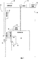
- Figure 1 schematically illustrates selected portions of an elevator system including bi-directional wireless power transfer designed according to an example embodiment.
- FIG. 1 schematically illustrates selected portions of an illustrative example elevator system 20.
- An elevator car 22 is situated within a hoistway 24.
- the manner in which the elevator car 22 is situated within the hoistway 24 and the mechanism by which it is propelled along the hoistway may vary depending on the particular embodiment and such details are not provided to maintain simplicity of the schematic illustration.
- a first transceiver 30 is supported on the elevator car 22.
- the first transceiver 30 is configured to wirelessly communicate with a second transceiver 32 that is at a preselected location relative to the hoistway 24.
- the second transceiver 32 is situated within the hoistway 24.
- the transceivers 30, 32 can wirelessly communicate with each other to transfer electrical power, data or other signals between the transceivers 30, 32.
- the transceivers 30 and 32 are configured for bi-directional wireless communications. In other words, some communications are from the first transceiver 30 to the second transceiver 32 and others are from the second transceiver 32 to the first transceiver 30.
- the illustrated example embodiment includes a plurality of second transceivers 32 situated in different, respective locations along the hoistway 24 so that wireless communication between the first transceiver 30 and a corresponding second transceiver 32 is possible when the elevator car 22 is at an appropriate location within the hoistway 24.
- a second transceiver 32 is positioned near each expected location of the elevator car 22 when the elevator car 22 is parked at a landing where elevator service is available to passengers.
- the number of second transceivers 32 and the location of each may vary to suit the needs of a particular installation.
- a power storage device 34 is supported on the elevator car 22.
- the power storage device 34 in some embodiments comprises a battery.
- the power storage device 34 can be a rechargeable lithium ion battery in some embodiments.
- Other embodiments include a power storage device 34 that is based on at least one of electrical, electromagnetic, electrochemical, or chemical technology.
- the power storage device 34 may include capacitors, supercapacitors, superconducting magnetic energy storage coils, a flow battery, or a combination of such devices.
- the power storage device 34 is configured to provide power to components on the elevator car 22 that require electrical power.
- a car operating panel (COP) 36 includes a passenger interface that allows a passenger to make a request for service from the elevator system 20.
- the car operating panel 36 may include, for example, a touchscreen or series of buttons that allow a passenger to indicate a desired destination.
- the car operating panel 36 includes an emergency request button 38 that allows a passenger to request emergency service if the elevator car 22 were to unexpectedly stop in the hoistway 24 in a position where the passenger was not able to exit the elevator car 22.
- the emergency request button 38 may be a physical button or may be an image on a touchscreen.
- Signals from the car operating panel 36 may be transmitted by the first transceiver 30 to the second transceiver 32 to then be communicated to the controller 28 that responsively causes appropriate operation of the machine 26 to provide desired elevator service.
- Signal communication from the second transceiver 32 to the first transceiver 30 may be used, for example, to control operation of one or more components of the elevator car 22, such as a door mover to open or close the doors.
- the elevator system 20 has a first operating condition in which power supply to the elevator system 20 is available from a main power supply, such as a building power supply or power grid operated by a utility company.
- a main power supply such as a building power supply or power grid operated by a utility company.
- power from the main power supply is transferred from the second transceiver 32 to the first transceiver 30 so that the power storage device 34 may store such power.
- This transfer of power from the second transceiver 32 to the first transceiver 30 keeps the power storage device 34 properly charged to be able to power components on the elevator car 22, such as the car operating panel 36, lighting, a door mover for opening and closing the doors, a ventilation fan, etc.
- a second operating condition of the elevator system 20 occurs when the main power supply is unavailable, such as during a power outage.
- a backup power supply 40 provides power to the machine 26 and controller 28 and other portions of the elevator system 20.
- the backup power supply 40 may be a generator, a battery or another power storage device that is based on at least one of electrical, electromagnetic, electrochemical, mechanical, or chemical technology.
- the backup power supply 40 may include capacitors, supercapacitors, superconducting magnetic energy storage coils, a flow battery, a flywheel, compressed fluid, a temperature storage medium, or a combination of more than one of these.
- the first transceiver 30 can transfer power from the power storage device 34 to the second transceiver 32 to provide additional power to the backup power supply 40 when needed. For example, if the backup power supply 40 is drained, is becoming depleted, or has insufficient reserve to continue a desired level of elevator system operation, power from the power storage device 34 can be used to increase the power of the backup power supply 40.
- a passenger in the elevator car 22 may use the emergency request button 38 to indicate a desire to notify someone that the elevator car 22 has stopped, for example, and that the passenger cannot exit the elevator car 22.
- the first transceiver 30 wirelessly communicates a signal based on operation of the emergency request button 38 to the second transceiver 32, which communicates that signal to the controller 28 or a remotely located monitoring center.
- the controller 28 may respond to such a signal by causing the elevator car 22 to move to a nearby landing or to open the car doors if the elevator car 22 is already situated at an appropriate landing.
- the illustrated example embodiment includes an emergency request indicator 44 that indicates use of the emergency request button 38.
- the indictor 44 is schematically shown as a physical indicator that may be situated at various locations in the building that includes the elevator system 20.
- the indicator 44 may be in a pit or machine room of the elevator system 20 where a mechanic or service personnel would observe the indication when arriving at the site of the elevator system 20 to address the second condition.
- the indicator 44 schematically represents a communication that is sent to a remote location where appropriate personnel are alerted to the need to communicate with the passenger in the elevator car 22 or to otherwise take action so that the elevator car 22 can be moved to an appropriate position and the doors can be opened so the passenger can exit the car. Communications with the passenger in the elevator car 22 under the second condition may occur through wireless communications between the second transceiver 32 and the first transceiver 30.
- the illustrated example elevator system 20 and other embodiments include bi-directional wireless communication between the elevator car 22 and at least one device strategically positioned along the travel path of the elevator car 22, which may include several, respective locations in the hoistway 24.
- the bi-directional communication allows for bi-directional power transfer between the power storage device 34 and the backup power supply 40.
- the bi-directional communication also allows for data or signal communications between passengers on the elevator car 22 or components of the elevator car 22 and other portions of the elevator system 20, such as the controller 28, or remote locations.
Landscapes
- Engineering & Computer Science (AREA)
- Automation & Control Theory (AREA)
- Computer Networks & Wireless Communication (AREA)
- Power Engineering (AREA)
- Structural Engineering (AREA)
- Civil Engineering (AREA)
- Mechanical Engineering (AREA)
- Business, Economics & Management (AREA)
- Emergency Management (AREA)
- Elevator Control (AREA)
- Maintenance And Inspection Apparatuses For Elevators (AREA)
- Indicating And Signalling Devices For Elevators (AREA)
Abstract
Description
- Elevator systems are in widespread use for carrying passengers between various levels in buildings, for example. Typical elevator systems include an elevator car situated within a hoistway. A machine uses electrical power to move the elevator car and control the position of the car within the hoistway. A controller controls operation of the machine.
- In traditional elevator systems, communications between the car operating panel in the elevator car and the controller occur over a hardwired connection established through a traveling cable associated with the elevator car. The traveling cable typically also acts as a conduit for electrical power to be supplied to the components of the elevator car, such as the lighting, door and car operating panel.
- Traditional elevator system configurations, including a traveling cable, have costs associated with them. For example, a traveling cable introduces additional material cost and other portions of the elevator system have to be configured to accommodate the traveling cable. Eliminating a travelling cable, however, is not possible without making some other modification to an elevator system to facilitate power supply and communications with components of the elevator car.
- An illustrative example embodiment of an elevator system includes an elevator car, a first transceiver supported on the elevator car, and a second transceiver in a preselected location where the first transceiver can wirelessly communicate with the second transceiver when the elevator car is situated in a corresponding location. The first transceiver wirelessly communicates with the second transceiver to wirelessly transfer at least electrical power between the transceivers. An elevator car power storage device is supported on the elevator car. The elevator car power storage device is configured to store electrical power received by the first transceiver from the second transceiver. The elevator car power storage device is also configured to provide power to the first transceiver to be transferred to the second transceiver.
- In addition to one or more of the features described above, or as an alternative, the elevator system includes a plurality of second transceivers in respective preselected locations, each of the second transceivers being configured to wirelessly communicate with the first transceiver when the elevator car is in a respective corresponding location.
- In addition to one or more of the features described above, or as an alternative, the elevator system includes a backup power storage that is configured to provide power to the elevator system under selected conditions, wherein the backup power storage is configured to receive power from the elevator car power storage device that is wirelessly transferred from the first transceiver to the second transceiver.
- In addition to one or more of the features described above, or as an alternative, the elevator system includes a machine including a motor configured to move the elevator car, and a controller configured to control operation of the motor. The backup power storage provides power to the controller and the machine during a power failure of a main power supply.
- In addition to one or more of the features described above, or as an alternative, the elevator car power storage device is configured to provide power to at least one electrically powered component of the elevator car.
- In addition to one or more of the features described above, or as an alternative, the elevator system includes a passenger interface supported on the elevator car and wherein the elevator car power storage device provides power to the passenger interface.
- In addition to one or more of the features described above, or as an alternative, the first transceiver and the second transceiver are configured to wirelessly communicate signals between the transceivers and the first transceiver wirelessly transfers at least one signal from at least one component on the elevator car to the second transceiver.
- In addition to one or more of the features described above, or as an alternative, the elevator system includes at least one passenger interface that is configured to generate at least one signal indicating a request of a passenger on the elevator car and wherein the first transceiver transfers a signal generated by the at least one passenger interface to the second transceiver.
- In addition to one or more of the features described above, or as an alternative, the at least one passenger interface is configured to allow the passenger to request elevator service to a selected destination or to request emergency service.
- In addition to one or more of the features described above, or as an alternative, the elevator car power storage device includes a battery.
- An illustrative example embodiment of a method of powering an elevator system includes wirelessly transferring power between a first transceiver supported on an elevator car and a second transceiver in a preselected location where the first transceiver can wirelessly communicate with the second transceiver when the elevator car is situated in a corresponding location, storing power transferred from the second transceiver to the first transceiver in an elevator car power storage device supported on the elevator car when the elevator system is in a first condition, and transferring power from the elevator car power storage device through the first transceiver to the second transceiver when the elevator system is in a second condition.
- In addition to one or more of the features described above, or as an alternative, the first condition includes the elevator system receiving power from a power supply outside of the elevator system and the second condition includes a failure of the power supply.
- In addition to one or more of the features described above, or as an alternative, the method includes providing power to a backup power storage when the elevator system is in the second condition, wherein the backup power storage is configured to receive power from the elevator car power storage device that is wirelessly transferred from the first transceiver to the second transceiver.
- In addition to one or more of the features described above, or as an alternative, the elevator system includes a machine having a motor configured to move the elevator car and a controller configured to control operation of the motor, and the method includes providing power from the backup power storage to the controller and the machine when the elevator system is in the second condition.
- In addition to one or more of the features described above, or as an alternative, the method includes providing power from the elevator car power storage device to at least one electrically powered component of the elevator car.
- In addition to one or more of the features described above, or as an alternative, the elevator system includes a passenger interface supported on the elevator car and the method includes providing power from the elevator car power storage device to the passenger interface.
- In addition to one or more of the features described above, or as an alternative, the method includes wirelessly communicating signals between the first transceiver and the second transceiver including transferring at least one signal from at least one component on the elevator car through the first transceiver to the second transceiver.
- In addition to one or more of the features described above, or as an alternative, the elevator system includes at least one passenger interface that is configured to generate at least one signal indicating a request of a passenger on the elevator car and the method includes transferring a signal generated by the at least one passenger interface through the first transceiver to the second transceiver.
- In addition to one or more of the features described above, or as an alternative, the at least one passenger interface is configured to allow the passenger to request elevator service to a selected destination or to request emergency service.
- In addition to one or more of the features described above, or as an alternative, the elevator car power storage device includes a battery.
- The various features and advantages of at least one disclosed example embodiment will become apparent to those skilled in the art from the following detailed description. The drawings that accompany the detailed description can be briefly described as follows.
-
Figure 1 schematically illustrates selected portions of an elevator system including bi-directional wireless power transfer designed according to an example embodiment. -
Figure 1 schematically illustrates selected portions of an illustrativeexample elevator system 20. Anelevator car 22 is situated within ahoistway 24. Amachine 26, including a motor and brake, operates responsive to acontroller 28 to control the position and movement of theelevator car 22 within thehoistway 24. The manner in which theelevator car 22 is situated within thehoistway 24 and the mechanism by which it is propelled along the hoistway may vary depending on the particular embodiment and such details are not provided to maintain simplicity of the schematic illustration. - A
first transceiver 30 is supported on theelevator car 22. Thefirst transceiver 30 is configured to wirelessly communicate with asecond transceiver 32 that is at a preselected location relative to thehoistway 24. In the illustrated example embodiment, thesecond transceiver 32 is situated within thehoistway 24. Other arrangements are possible. When theelevator car 22 is situated in a corresponding location where thefirst transceiver 30 andsecond transceiver 32 are within an acceptable communication distance for wireless communications between them, thetransceivers transceivers - The
transceivers first transceiver 30 to thesecond transceiver 32 and others are from thesecond transceiver 32 to thefirst transceiver 30. - The illustrated example embodiment includes a plurality of
second transceivers 32 situated in different, respective locations along thehoistway 24 so that wireless communication between thefirst transceiver 30 and a correspondingsecond transceiver 32 is possible when theelevator car 22 is at an appropriate location within thehoistway 24. In some embodiments, asecond transceiver 32 is positioned near each expected location of theelevator car 22 when theelevator car 22 is parked at a landing where elevator service is available to passengers. The number ofsecond transceivers 32 and the location of each may vary to suit the needs of a particular installation. - A
power storage device 34 is supported on theelevator car 22. Thepower storage device 34 in some embodiments comprises a battery. For example, thepower storage device 34 can be a rechargeable lithium ion battery in some embodiments. Other embodiments include apower storage device 34 that is based on at least one of electrical, electromagnetic, electrochemical, or chemical technology. For example, thepower storage device 34 may include capacitors, supercapacitors, superconducting magnetic energy storage coils, a flow battery, or a combination of such devices. - The
power storage device 34 is configured to provide power to components on theelevator car 22 that require electrical power. For example, inFigure 1 a car operating panel (COP) 36 includes a passenger interface that allows a passenger to make a request for service from theelevator system 20. Thecar operating panel 36 may include, for example, a touchscreen or series of buttons that allow a passenger to indicate a desired destination. In the illustrated example, thecar operating panel 36 includes anemergency request button 38 that allows a passenger to request emergency service if theelevator car 22 were to unexpectedly stop in thehoistway 24 in a position where the passenger was not able to exit theelevator car 22. Theemergency request button 38 may be a physical button or may be an image on a touchscreen. - Signals from the
car operating panel 36 may be transmitted by thefirst transceiver 30 to thesecond transceiver 32 to then be communicated to thecontroller 28 that responsively causes appropriate operation of themachine 26 to provide desired elevator service. Signal communication from thesecond transceiver 32 to thefirst transceiver 30 may be used, for example, to control operation of one or more components of theelevator car 22, such as a door mover to open or close the doors. - The
elevator system 20 has a first operating condition in which power supply to theelevator system 20 is available from a main power supply, such as a building power supply or power grid operated by a utility company. In the first condition, power from the main power supply is transferred from thesecond transceiver 32 to thefirst transceiver 30 so that thepower storage device 34 may store such power. This transfer of power from thesecond transceiver 32 to thefirst transceiver 30 keeps thepower storage device 34 properly charged to be able to power components on theelevator car 22, such as thecar operating panel 36, lighting, a door mover for opening and closing the doors, a ventilation fan, etc. - A second operating condition of the
elevator system 20 occurs when the main power supply is unavailable, such as during a power outage. In the second condition, abackup power supply 40 provides power to themachine 26 andcontroller 28 and other portions of theelevator system 20. Thebackup power supply 40 may be a generator, a battery or another power storage device that is based on at least one of electrical, electromagnetic, electrochemical, mechanical, or chemical technology. For example, thebackup power supply 40 may include capacitors, supercapacitors, superconducting magnetic energy storage coils, a flow battery, a flywheel, compressed fluid, a temperature storage medium, or a combination of more than one of these. In the second condition, thefirst transceiver 30 can transfer power from thepower storage device 34 to thesecond transceiver 32 to provide additional power to thebackup power supply 40 when needed. For example, if thebackup power supply 40 is drained, is becoming depleted, or has insufficient reserve to continue a desired level of elevator system operation, power from thepower storage device 34 can be used to increase the power of thebackup power supply 40. - Additionally, during the second condition, a passenger in the
elevator car 22 may use theemergency request button 38 to indicate a desire to notify someone that theelevator car 22 has stopped, for example, and that the passenger cannot exit theelevator car 22. Thefirst transceiver 30 wirelessly communicates a signal based on operation of theemergency request button 38 to thesecond transceiver 32, which communicates that signal to thecontroller 28 or a remotely located monitoring center. Thecontroller 28 may respond to such a signal by causing theelevator car 22 to move to a nearby landing or to open the car doors if theelevator car 22 is already situated at an appropriate landing. - The illustrated example embodiment includes an
emergency request indicator 44 that indicates use of theemergency request button 38. Theindictor 44 is schematically shown as a physical indicator that may be situated at various locations in the building that includes theelevator system 20. For example, theindicator 44 may be in a pit or machine room of theelevator system 20 where a mechanic or service personnel would observe the indication when arriving at the site of theelevator system 20 to address the second condition. Alternatively, theindicator 44 schematically represents a communication that is sent to a remote location where appropriate personnel are alerted to the need to communicate with the passenger in theelevator car 22 or to otherwise take action so that theelevator car 22 can be moved to an appropriate position and the doors can be opened so the passenger can exit the car. Communications with the passenger in theelevator car 22 under the second condition may occur through wireless communications between thesecond transceiver 32 and thefirst transceiver 30. - The illustrated
example elevator system 20 and other embodiments include bi-directional wireless communication between theelevator car 22 and at least one device strategically positioned along the travel path of theelevator car 22, which may include several, respective locations in thehoistway 24. The bi-directional communication allows for bi-directional power transfer between thepower storage device 34 and thebackup power supply 40. The bi-directional communication also allows for data or signal communications between passengers on theelevator car 22 or components of theelevator car 22 and other portions of theelevator system 20, such as thecontroller 28, or remote locations. - The preceding description is exemplary rather than limiting in nature. Variations and modifications to the disclosed examples may become apparent to those skilled in the art that do not necessarily depart from the essence of this invention. The scope of legal protection given to this invention can only be determined by studying the following claims.
Claims (15)
- An elevator system, comprising:an elevator car;a first transceiver supported on the elevator car;a second transceiver in a preselected location where the first transceiver can wirelessly communicate with the second transceiver when the elevator car is situated in a corresponding location, the first transceiver wirelessly communicating with the second transceiver to transfer at least electrical power between the transceivers; andan elevator car power storage device supported on the elevator car, the elevator car power storage device being configured to store electrical power received by the first transceiver from the second transceiver, the elevator car power storage device also being configured to provide power to the first transceiver to be transferred to the second transceiver.
- The elevator system of claim 1, comprising a plurality of second transceivers in respective preselected locations, each of the second transceivers being configured to wirelessly communicate with the first transceiver when the elevator car is in a respective corresponding location.
- The elevator system of claim 1 or 2, comprising a backup power storage that is configured to provide power to the elevator system under selected conditions, wherein the backup power storage is configured to receive power from the elevator car power storage device that is wirelessly transferred from the first transceiver to the second transceiver.
- The elevator system of claim 3, comprisinga machine including a motor configured to move the elevator car, anda controller configured to control operation of the motor,wherein the backup power storage provides power to the controller and the machine during a power failure of a main power supply.
- The elevator system of any preceding claim, wherein the elevator car power storage device is configured to provide power to at least one electrically powered component of the elevator car.
- The elevator system of claim 5, comprising a passenger interface supported on the elevator car and wherein the elevator car power storage device provides power to the passenger interface.
- The elevator system of any preceding claim, wherein the first transceiver and the second transceiver are configured to wirelessly communicate signals between the transceivers and the first transceiver wirelessly transfers at least one signal from at least one component on the elevator car to the second transceiver.
- The elevator system of claim 7, comprising at least one passenger interface that is configured to generate at least one signal indicating a request of a passenger on the elevator car and wherein the first transceiver transfers a signal generated by the at least one passenger interface to the second transceiver.
- The elevator system of claim 8, wherein the at least one passenger interface is configured to allow the passenger to request elevator service to a selected destination or to request emergency service.
- The elevator system of any preceding claim, wherein the elevator car power storage device comprises a battery.
- A method of powering an elevator system, the method comprising:wirelessly transferring power between a first transceiver supported on an elevator car and a second transceiver in a preselected location where the first transceiver can wirelessly communicate with the second transceiver when the elevator car is situated in a corresponding location;storing power transferred from the second transceiver to the first transceiver in an elevator car power storage device supported on the elevator car when the elevator system is in a first condition; andtransferring power from the elevator car power storage device through the first transceiver to the second transceiver when the elevator system is in a second condition.
- The method of claim 11, wherein the first condition includes the elevator system receiving power from a power supply outside of the elevator system and the second condition includes a failure of the power supply.
- The method of claim 11 or 12, comprising providing power to a backup power storage when the elevator system is in the second condition, wherein the backup power storage is configured to receive power from the elevator car power storage device that is wirelessly transferred from the first transceiver to the second transceiver.
- The method of claim 13, wherein the elevator system includes a machine having a motor configured to move the elevator car and a controller configured to control operation of the motor, and the method comprises providing power from the backup power storage to the controller and the machine when the elevator system is in the second condition.
- The method of any of claims 11 to 14, comprising wirelessly communicating signals between the first transceiver and the second transceiver including transferring at least one signal from at least one component on the elevator car through the first transceiver to the second transceiver;optionally wherein the elevator system includes at least one passenger interface that is configured to generate at least one signal indicating a request of a passenger on the elevator car and the method comprises transferring a signal generated by the at least one passenger interface through the first transceiver to the second transceiver;further optionally wherein the at least one passenger interface is configured to allow the passenger to request elevator service to a selected destination or to request emergency service.
Applications Claiming Priority (1)
| Application Number | Priority Date | Filing Date | Title |
|---|---|---|---|
| US17/061,960 US20220106155A1 (en) | 2020-10-02 | 2020-10-02 | Elevator system including wireless power transfer |
Publications (2)
| Publication Number | Publication Date |
|---|---|
| EP3978408A1 true EP3978408A1 (en) | 2022-04-06 |
| EP3978408B1 EP3978408B1 (en) | 2023-11-29 |
Family
ID=77838738
Family Applications (1)
| Application Number | Title | Priority Date | Filing Date |
|---|---|---|---|
| EP21197562.8A Active EP3978408B1 (en) | 2020-10-02 | 2021-09-17 | Elevator system including wireless power transfer |
Country Status (4)
| Country | Link |
|---|---|
| US (1) | US20220106155A1 (en) |
| EP (1) | EP3978408B1 (en) |
| KR (1) | KR20220044672A (en) |
| CN (1) | CN114380169B (en) |
Cited By (1)
| Publication number | Priority date | Publication date | Assignee | Title |
|---|---|---|---|---|
| US20230278831A1 (en) * | 2022-03-03 | 2023-09-07 | Brandsafway Services Llc | Ultracapacitor powered construction elevator |
Families Citing this family (3)
| Publication number | Priority date | Publication date | Assignee | Title |
|---|---|---|---|---|
| EP3705436B1 (en) * | 2019-03-07 | 2026-02-25 | KONE Corporation | An energy storage system for an elevator car, and a method and an apparatus for monitoring the energy storage system |
| JP7424414B2 (en) * | 2022-06-21 | 2024-01-30 | フジテック株式会社 | elevator power supply system |
| JP7785216B1 (en) * | 2025-02-18 | 2025-12-12 | 三菱電機ビルソリューションズ株式会社 | Elevator car equipment mounting device |
Citations (4)
| Publication number | Priority date | Publication date | Assignee | Title |
|---|---|---|---|---|
| US6412604B1 (en) * | 1999-05-25 | 2002-07-02 | Inventio Ag | Device for transferring energy to a vehicle of a transportation system |
| JP2012184049A (en) * | 2011-03-03 | 2012-09-27 | Toshiba Elevator Co Ltd | Elevator |
| US20170057780A1 (en) * | 2015-09-01 | 2017-03-02 | Otis Elevator Company | Elevator wireless communication and power transfer system |
| JP2019156545A (en) * | 2018-03-09 | 2019-09-19 | 東芝エレベータ株式会社 | Non-contact power supply system for elevator |
Family Cites Families (14)
| Publication number | Priority date | Publication date | Assignee | Title |
|---|---|---|---|---|
| JP3857508B2 (en) * | 2000-08-29 | 2006-12-13 | 株式会社日立製作所 | Elevator equipment |
| JP4122973B2 (en) * | 2001-01-19 | 2008-07-23 | 株式会社日立製作所 | Elevator |
| WO2006069591A1 (en) * | 2004-12-31 | 2006-07-06 | Otis Elevator Company | Elevator rescue operation control system |
| CN101146729B (en) * | 2005-04-01 | 2011-02-02 | 三菱电机株式会社 | Elevator power supply system |
| CN101902081B (en) * | 2010-03-16 | 2013-10-30 | 苏州康开电气有限公司 | Floor non-contact power supply device of lift car |
| WO2015025438A1 (en) * | 2013-08-23 | 2015-02-26 | 三菱電機エンジニアリング株式会社 | Resonant power transmission device and resonant power multiplexed transmission system |
| US9837860B2 (en) * | 2014-05-05 | 2017-12-05 | Witricity Corporation | Wireless power transmission systems for elevators |
| US9866039B2 (en) * | 2015-11-13 | 2018-01-09 | X Development Llc | Wireless power delivery over medium range distances using magnetic, and common and differential mode-electric, near-field coupling |
| JP2018024496A (en) * | 2016-08-09 | 2018-02-15 | 株式会社日立製作所 | Elevator device |
| JP2019011141A (en) * | 2017-06-29 | 2019-01-24 | 株式会社日立製作所 | Non-contact power supply system |
| US11218024B2 (en) * | 2018-12-14 | 2022-01-04 | Otis Elevator Company | Multi-shaft power charging |
| US11670961B2 (en) * | 2018-12-14 | 2023-06-06 | Otis Elevator Company | Closed loop control wireless power transmission system for conveyance system |
| US11682929B2 (en) * | 2018-12-14 | 2023-06-20 | Otis Elevator Company | Car to car wireless power transfer |
| US20200195047A1 (en) * | 2018-12-14 | 2020-06-18 | Otis Elevator Company | Car to call point wireless power charging |
-
2020
- 2020-10-02 US US17/061,960 patent/US20220106155A1/en active Pending
-
2021
- 2021-07-20 CN CN202110818838.1A patent/CN114380169B/en active Active
- 2021-09-17 EP EP21197562.8A patent/EP3978408B1/en active Active
- 2021-09-30 KR KR1020210129441A patent/KR20220044672A/en active Pending
Patent Citations (4)
| Publication number | Priority date | Publication date | Assignee | Title |
|---|---|---|---|---|
| US6412604B1 (en) * | 1999-05-25 | 2002-07-02 | Inventio Ag | Device for transferring energy to a vehicle of a transportation system |
| JP2012184049A (en) * | 2011-03-03 | 2012-09-27 | Toshiba Elevator Co Ltd | Elevator |
| US20170057780A1 (en) * | 2015-09-01 | 2017-03-02 | Otis Elevator Company | Elevator wireless communication and power transfer system |
| JP2019156545A (en) * | 2018-03-09 | 2019-09-19 | 東芝エレベータ株式会社 | Non-contact power supply system for elevator |
Cited By (1)
| Publication number | Priority date | Publication date | Assignee | Title |
|---|---|---|---|---|
| US20230278831A1 (en) * | 2022-03-03 | 2023-09-07 | Brandsafway Services Llc | Ultracapacitor powered construction elevator |
Also Published As
| Publication number | Publication date |
|---|---|
| EP3978408B1 (en) | 2023-11-29 |
| KR20220044672A (en) | 2022-04-11 |
| US20220106155A1 (en) | 2022-04-07 |
| CN114380169B (en) | 2024-08-16 |
| CN114380169A (en) | 2022-04-22 |
Similar Documents
| Publication | Publication Date | Title |
|---|---|---|
| EP3978408B1 (en) | Elevator system including wireless power transfer | |
| CN108349685B (en) | Elevator energy solution | |
| JP6751012B2 (en) | Elevator | |
| EP1864932A1 (en) | Electric-power supply system for elevator | |
| US12509327B2 (en) | Energy storage system for an elevator car, and a method and an apparatus for monitoring the energy storage system | |
| US20210016993A1 (en) | Elevator system | |
| KR20120032019A (en) | Elevator rescue system | |
| KR102130234B1 (en) | A method for operating a lift system, and a lift system designed to perform the method | |
| EP3431433A2 (en) | Elevator car power supply system | |
| CN103863906B (en) | Possesses the electric system of the building of elevator | |
| WO2002057171A1 (en) | Elevator | |
| EP3674239B1 (en) | Hybrid energy storage system architectures | |
| JP2017218264A (en) | Elevator car position detection system | |
| BR112018005385B1 (en) | MONITORING DEVICE FOR AN ELEVATOR INSTALLATION, MOUNTING DEVICE FOR ASSEMBLY OF WELL EQUIPMENT AND METHOD FOR ASSEMBLY AN ELEVATOR INSTALLATION | |
| KR20220143086A (en) | elevator | |
| JP2019218149A (en) | Elevator system | |
| US20220169480A1 (en) | Elevator system | |
| CN111186740B (en) | Elevator alarm system | |
| JP2005145652A (en) | Electric power supply system for elevator | |
| CN103863905B (en) | Possesses the power system of the building of lift | |
| KR20210032806A (en) | The elevator emergency driving device | |
| JP2020001888A (en) | Elevator system | |
| EP3670412B1 (en) | Energy-aware dispatching for conveyance systems | |
| JP7349074B1 (en) | elevator | |
| US12545554B2 (en) | Elevator system |
Legal Events
| Date | Code | Title | Description |
|---|---|---|---|
| PUAI | Public reference made under article 153(3) epc to a published international application that has entered the european phase |
Free format text: ORIGINAL CODE: 0009012 |
|
| STAA | Information on the status of an ep patent application or granted ep patent |
Free format text: STATUS: THE APPLICATION HAS BEEN PUBLISHED |
|
| AK | Designated contracting states |
Kind code of ref document: A1 Designated state(s): AL AT BE BG CH CY CZ DE DK EE ES FI FR GB GR HR HU IE IS IT LI LT LU LV MC MK MT NL NO PL PT RO RS SE SI SK SM TR |
|
| STAA | Information on the status of an ep patent application or granted ep patent |
Free format text: STATUS: REQUEST FOR EXAMINATION WAS MADE |
|
| 17P | Request for examination filed |
Effective date: 20220914 |
|
| RBV | Designated contracting states (corrected) |
Designated state(s): AL AT BE BG CH CY CZ DE DK EE ES FI FR GB GR HR HU IE IS IT LI LT LU LV MC MK MT NL NO PL PT RO RS SE SI SK SM TR |
|
| GRAP | Despatch of communication of intention to grant a patent |
Free format text: ORIGINAL CODE: EPIDOSNIGR1 |
|
| STAA | Information on the status of an ep patent application or granted ep patent |
Free format text: STATUS: GRANT OF PATENT IS INTENDED |
|
| INTG | Intention to grant announced |
Effective date: 20230628 |
|
| GRAS | Grant fee paid |
Free format text: ORIGINAL CODE: EPIDOSNIGR3 |
|
| GRAA | (expected) grant |
Free format text: ORIGINAL CODE: 0009210 |
|
| STAA | Information on the status of an ep patent application or granted ep patent |
Free format text: STATUS: THE PATENT HAS BEEN GRANTED |
|
| AK | Designated contracting states |
Kind code of ref document: B1 Designated state(s): AL AT BE BG CH CY CZ DE DK EE ES FI FR GB GR HR HU IE IS IT LI LT LU LV MC MK MT NL NO PL PT RO RS SE SI SK SM TR |
|
| REG | Reference to a national code |
Ref country code: GB Ref legal event code: FG4D |
|
| REG | Reference to a national code |
Ref country code: CH Ref legal event code: EP |
|
| REG | Reference to a national code |
Ref country code: IE Ref legal event code: FG4D |
|
| REG | Reference to a national code |
Ref country code: DE Ref legal event code: R096 Ref document number: 602021007239 Country of ref document: DE |
|
| REG | Reference to a national code |
Ref country code: LT Ref legal event code: MG9D |
|
| REG | Reference to a national code |
Ref country code: NL Ref legal event code: MP Effective date: 20231129 |
|
| PG25 | Lapsed in a contracting state [announced via postgrant information from national office to epo] |
Ref country code: GR Free format text: LAPSE BECAUSE OF FAILURE TO SUBMIT A TRANSLATION OF THE DESCRIPTION OR TO PAY THE FEE WITHIN THE PRESCRIBED TIME-LIMIT Effective date: 20240301 |
|
| PG25 | Lapsed in a contracting state [announced via postgrant information from national office to epo] |
Ref country code: IS Free format text: LAPSE BECAUSE OF FAILURE TO SUBMIT A TRANSLATION OF THE DESCRIPTION OR TO PAY THE FEE WITHIN THE PRESCRIBED TIME-LIMIT Effective date: 20240329 |
|
| PG25 | Lapsed in a contracting state [announced via postgrant information from national office to epo] |
Ref country code: LT Free format text: LAPSE BECAUSE OF FAILURE TO SUBMIT A TRANSLATION OF THE DESCRIPTION OR TO PAY THE FEE WITHIN THE PRESCRIBED TIME-LIMIT Effective date: 20231129 |
|
| PG25 | Lapsed in a contracting state [announced via postgrant information from national office to epo] |
Ref country code: ES Free format text: LAPSE BECAUSE OF FAILURE TO SUBMIT A TRANSLATION OF THE DESCRIPTION OR TO PAY THE FEE WITHIN THE PRESCRIBED TIME-LIMIT Effective date: 20231129 |
|
| PG25 | Lapsed in a contracting state [announced via postgrant information from national office to epo] |
Ref country code: LT Free format text: LAPSE BECAUSE OF FAILURE TO SUBMIT A TRANSLATION OF THE DESCRIPTION OR TO PAY THE FEE WITHIN THE PRESCRIBED TIME-LIMIT Effective date: 20231129 Ref country code: IS Free format text: LAPSE BECAUSE OF FAILURE TO SUBMIT A TRANSLATION OF THE DESCRIPTION OR TO PAY THE FEE WITHIN THE PRESCRIBED TIME-LIMIT Effective date: 20240329 Ref country code: GR Free format text: LAPSE BECAUSE OF FAILURE TO SUBMIT A TRANSLATION OF THE DESCRIPTION OR TO PAY THE FEE WITHIN THE PRESCRIBED TIME-LIMIT Effective date: 20240301 Ref country code: ES Free format text: LAPSE BECAUSE OF FAILURE TO SUBMIT A TRANSLATION OF THE DESCRIPTION OR TO PAY THE FEE WITHIN THE PRESCRIBED TIME-LIMIT Effective date: 20231129 Ref country code: BG Free format text: LAPSE BECAUSE OF FAILURE TO SUBMIT A TRANSLATION OF THE DESCRIPTION OR TO PAY THE FEE WITHIN THE PRESCRIBED TIME-LIMIT Effective date: 20240229 |
|
| REG | Reference to a national code |
Ref country code: AT Ref legal event code: MK05 Ref document number: 1635937 Country of ref document: AT Kind code of ref document: T Effective date: 20231129 |
|
| PG25 | Lapsed in a contracting state [announced via postgrant information from national office to epo] |
Ref country code: NL Free format text: LAPSE BECAUSE OF FAILURE TO SUBMIT A TRANSLATION OF THE DESCRIPTION OR TO PAY THE FEE WITHIN THE PRESCRIBED TIME-LIMIT Effective date: 20231129 |
|
| PG25 | Lapsed in a contracting state [announced via postgrant information from national office to epo] |
Ref country code: SE Free format text: LAPSE BECAUSE OF FAILURE TO SUBMIT A TRANSLATION OF THE DESCRIPTION OR TO PAY THE FEE WITHIN THE PRESCRIBED TIME-LIMIT Effective date: 20231129 Ref country code: RS Free format text: LAPSE BECAUSE OF FAILURE TO SUBMIT A TRANSLATION OF THE DESCRIPTION OR TO PAY THE FEE WITHIN THE PRESCRIBED TIME-LIMIT Effective date: 20231129 Ref country code: PL Free format text: LAPSE BECAUSE OF FAILURE TO SUBMIT A TRANSLATION OF THE DESCRIPTION OR TO PAY THE FEE WITHIN THE PRESCRIBED TIME-LIMIT Effective date: 20231129 Ref country code: NO Free format text: LAPSE BECAUSE OF FAILURE TO SUBMIT A TRANSLATION OF THE DESCRIPTION OR TO PAY THE FEE WITHIN THE PRESCRIBED TIME-LIMIT Effective date: 20240229 Ref country code: NL Free format text: LAPSE BECAUSE OF FAILURE TO SUBMIT A TRANSLATION OF THE DESCRIPTION OR TO PAY THE FEE WITHIN THE PRESCRIBED TIME-LIMIT Effective date: 20231129 Ref country code: LV Free format text: LAPSE BECAUSE OF FAILURE TO SUBMIT A TRANSLATION OF THE DESCRIPTION OR TO PAY THE FEE WITHIN THE PRESCRIBED TIME-LIMIT Effective date: 20231129 Ref country code: HR Free format text: LAPSE BECAUSE OF FAILURE TO SUBMIT A TRANSLATION OF THE DESCRIPTION OR TO PAY THE FEE WITHIN THE PRESCRIBED TIME-LIMIT Effective date: 20231129 |
|
| PG25 | Lapsed in a contracting state [announced via postgrant information from national office to epo] |
Ref country code: DK Free format text: LAPSE BECAUSE OF FAILURE TO SUBMIT A TRANSLATION OF THE DESCRIPTION OR TO PAY THE FEE WITHIN THE PRESCRIBED TIME-LIMIT Effective date: 20231129 |
|
| PG25 | Lapsed in a contracting state [announced via postgrant information from national office to epo] |
Ref country code: CZ Free format text: LAPSE BECAUSE OF FAILURE TO SUBMIT A TRANSLATION OF THE DESCRIPTION OR TO PAY THE FEE WITHIN THE PRESCRIBED TIME-LIMIT Effective date: 20231129 Ref country code: AT Free format text: LAPSE BECAUSE OF FAILURE TO SUBMIT A TRANSLATION OF THE DESCRIPTION OR TO PAY THE FEE WITHIN THE PRESCRIBED TIME-LIMIT Effective date: 20231129 |
|
| PG25 | Lapsed in a contracting state [announced via postgrant information from national office to epo] |
Ref country code: SK Free format text: LAPSE BECAUSE OF FAILURE TO SUBMIT A TRANSLATION OF THE DESCRIPTION OR TO PAY THE FEE WITHIN THE PRESCRIBED TIME-LIMIT Effective date: 20231129 |
|
| PG25 | Lapsed in a contracting state [announced via postgrant information from national office to epo] |
Ref country code: SM Free format text: LAPSE BECAUSE OF FAILURE TO SUBMIT A TRANSLATION OF THE DESCRIPTION OR TO PAY THE FEE WITHIN THE PRESCRIBED TIME-LIMIT Effective date: 20231129 Ref country code: SK Free format text: LAPSE BECAUSE OF FAILURE TO SUBMIT A TRANSLATION OF THE DESCRIPTION OR TO PAY THE FEE WITHIN THE PRESCRIBED TIME-LIMIT Effective date: 20231129 Ref country code: RO Free format text: LAPSE BECAUSE OF FAILURE TO SUBMIT A TRANSLATION OF THE DESCRIPTION OR TO PAY THE FEE WITHIN THE PRESCRIBED TIME-LIMIT Effective date: 20231129 Ref country code: IT Free format text: LAPSE BECAUSE OF FAILURE TO SUBMIT A TRANSLATION OF THE DESCRIPTION OR TO PAY THE FEE WITHIN THE PRESCRIBED TIME-LIMIT Effective date: 20231129 Ref country code: EE Free format text: LAPSE BECAUSE OF FAILURE TO SUBMIT A TRANSLATION OF THE DESCRIPTION OR TO PAY THE FEE WITHIN THE PRESCRIBED TIME-LIMIT Effective date: 20231129 Ref country code: DK Free format text: LAPSE BECAUSE OF FAILURE TO SUBMIT A TRANSLATION OF THE DESCRIPTION OR TO PAY THE FEE WITHIN THE PRESCRIBED TIME-LIMIT Effective date: 20231129 Ref country code: CZ Free format text: LAPSE BECAUSE OF FAILURE TO SUBMIT A TRANSLATION OF THE DESCRIPTION OR TO PAY THE FEE WITHIN THE PRESCRIBED TIME-LIMIT Effective date: 20231129 Ref country code: AT Free format text: LAPSE BECAUSE OF FAILURE TO SUBMIT A TRANSLATION OF THE DESCRIPTION OR TO PAY THE FEE WITHIN THE PRESCRIBED TIME-LIMIT Effective date: 20231129 |
|
| PG25 | Lapsed in a contracting state [announced via postgrant information from national office to epo] |
Ref country code: PT Free format text: LAPSE BECAUSE OF FAILURE TO SUBMIT A TRANSLATION OF THE DESCRIPTION OR TO PAY THE FEE WITHIN THE PRESCRIBED TIME-LIMIT Effective date: 20240401 |
|
| PG25 | Lapsed in a contracting state [announced via postgrant information from national office to epo] |
Ref country code: PT Free format text: LAPSE BECAUSE OF FAILURE TO SUBMIT A TRANSLATION OF THE DESCRIPTION OR TO PAY THE FEE WITHIN THE PRESCRIBED TIME-LIMIT Effective date: 20240401 |
|
| REG | Reference to a national code |
Ref country code: DE Ref legal event code: R097 Ref document number: 602021007239 Country of ref document: DE |
|
| PLBE | No opposition filed within time limit |
Free format text: ORIGINAL CODE: 0009261 |
|
| STAA | Information on the status of an ep patent application or granted ep patent |
Free format text: STATUS: NO OPPOSITION FILED WITHIN TIME LIMIT |
|
| PG25 | Lapsed in a contracting state [announced via postgrant information from national office to epo] |
Ref country code: SI Free format text: LAPSE BECAUSE OF FAILURE TO SUBMIT A TRANSLATION OF THE DESCRIPTION OR TO PAY THE FEE WITHIN THE PRESCRIBED TIME-LIMIT Effective date: 20231129 |
|
| PG25 | Lapsed in a contracting state [announced via postgrant information from national office to epo] |
Ref country code: SI Free format text: LAPSE BECAUSE OF FAILURE TO SUBMIT A TRANSLATION OF THE DESCRIPTION OR TO PAY THE FEE WITHIN THE PRESCRIBED TIME-LIMIT Effective date: 20231129 |
|
| 26N | No opposition filed |
Effective date: 20240830 |
|
| PG25 | Lapsed in a contracting state [announced via postgrant information from national office to epo] |
Ref country code: MC Free format text: LAPSE BECAUSE OF FAILURE TO SUBMIT A TRANSLATION OF THE DESCRIPTION OR TO PAY THE FEE WITHIN THE PRESCRIBED TIME-LIMIT Effective date: 20231129 |
|
| REG | Reference to a national code |
Ref country code: CH Ref legal event code: PL |
|
| PG25 | Lapsed in a contracting state [announced via postgrant information from national office to epo] |
Ref country code: LU Free format text: LAPSE BECAUSE OF NON-PAYMENT OF DUE FEES Effective date: 20240917 |
|
| REG | Reference to a national code |
Ref country code: BE Ref legal event code: MM Effective date: 20240930 |
|
| PG25 | Lapsed in a contracting state [announced via postgrant information from national office to epo] |
Ref country code: BE Free format text: LAPSE BECAUSE OF NON-PAYMENT OF DUE FEES Effective date: 20240930 |
|
| PG25 | Lapsed in a contracting state [announced via postgrant information from national office to epo] |
Ref country code: CH Free format text: LAPSE BECAUSE OF NON-PAYMENT OF DUE FEES Effective date: 20240930 |
|
| PG25 | Lapsed in a contracting state [announced via postgrant information from national office to epo] |
Ref country code: IE Free format text: LAPSE BECAUSE OF NON-PAYMENT OF DUE FEES Effective date: 20240917 |
|
| PG25 | Lapsed in a contracting state [announced via postgrant information from national office to epo] |
Ref country code: FI Free format text: LAPSE BECAUSE OF FAILURE TO SUBMIT A TRANSLATION OF THE DESCRIPTION OR TO PAY THE FEE WITHIN THE PRESCRIBED TIME-LIMIT Effective date: 20231129 |
|
| PGFP | Annual fee paid to national office [announced via postgrant information from national office to epo] |
Ref country code: DE Payment date: 20250820 Year of fee payment: 5 |
|
| PGFP | Annual fee paid to national office [announced via postgrant information from national office to epo] |
Ref country code: FR Payment date: 20250821 Year of fee payment: 5 |
|
| PG25 | Lapsed in a contracting state [announced via postgrant information from national office to epo] |
Ref country code: CY Free format text: LAPSE BECAUSE OF FAILURE TO SUBMIT A TRANSLATION OF THE DESCRIPTION OR TO PAY THE FEE WITHIN THE PRESCRIBED TIME-LIMIT; INVALID AB INITIO Effective date: 20210917 |
|
| PG25 | Lapsed in a contracting state [announced via postgrant information from national office to epo] |
Ref country code: HU Free format text: LAPSE BECAUSE OF FAILURE TO SUBMIT A TRANSLATION OF THE DESCRIPTION OR TO PAY THE FEE WITHIN THE PRESCRIBED TIME-LIMIT; INVALID AB INITIO Effective date: 20210917 |