EP3978313A1 - Automatic safety tripod for vehicle - Google Patents
Automatic safety tripod for vehicle Download PDFInfo
- Publication number
- EP3978313A1 EP3978313A1 EP20832579.5A EP20832579A EP3978313A1 EP 3978313 A1 EP3978313 A1 EP 3978313A1 EP 20832579 A EP20832579 A EP 20832579A EP 3978313 A1 EP3978313 A1 EP 3978313A1
- Authority
- EP
- European Patent Office
- Prior art keywords
- bar
- frame
- guide groove
- support bar
- support
- Prior art date
- Legal status (The legal status is an assumption and is not a legal conclusion. Google has not performed a legal analysis and makes no representation as to the accuracy of the status listed.)
- Withdrawn
Links
Images


Classifications
-
- B—PERFORMING OPERATIONS; TRANSPORTING
- B60—VEHICLES IN GENERAL
- B60Q—ARRANGEMENT OF SIGNALLING OR LIGHTING DEVICES, THE MOUNTING OR SUPPORTING THEREOF OR CIRCUITS THEREFOR, FOR VEHICLES IN GENERAL
- B60Q1/00—Arrangement of optical signalling or lighting devices, the mounting or supporting thereof or circuits therefor
- B60Q1/26—Arrangement of optical signalling or lighting devices, the mounting or supporting thereof or circuits therefor the devices being primarily intended to indicate the vehicle, or parts thereof, or to give signals, to other traffic
- B60Q1/30—Arrangement of optical signalling or lighting devices, the mounting or supporting thereof or circuits therefor the devices being primarily intended to indicate the vehicle, or parts thereof, or to give signals, to other traffic for indicating rear of vehicle, e.g. by means of reflecting surfaces
-
- B—PERFORMING OPERATIONS; TRANSPORTING
- B60—VEHICLES IN GENERAL
- B60Q—ARRANGEMENT OF SIGNALLING OR LIGHTING DEVICES, THE MOUNTING OR SUPPORTING THEREOF OR CIRCUITS THEREFOR, FOR VEHICLES IN GENERAL
- B60Q1/00—Arrangement of optical signalling or lighting devices, the mounting or supporting thereof or circuits therefor
- B60Q1/26—Arrangement of optical signalling or lighting devices, the mounting or supporting thereof or circuits therefor the devices being primarily intended to indicate the vehicle, or parts thereof, or to give signals, to other traffic
- B60Q1/2661—Arrangement of optical signalling or lighting devices, the mounting or supporting thereof or circuits therefor the devices being primarily intended to indicate the vehicle, or parts thereof, or to give signals, to other traffic mounted on parts having other functions
-
- B—PERFORMING OPERATIONS; TRANSPORTING
- B60—VEHICLES IN GENERAL
- B60Q—ARRANGEMENT OF SIGNALLING OR LIGHTING DEVICES, THE MOUNTING OR SUPPORTING THEREOF OR CIRCUITS THEREFOR, FOR VEHICLES IN GENERAL
- B60Q1/00—Arrangement of optical signalling or lighting devices, the mounting or supporting thereof or circuits therefor
- B60Q1/26—Arrangement of optical signalling or lighting devices, the mounting or supporting thereof or circuits therefor the devices being primarily intended to indicate the vehicle, or parts thereof, or to give signals, to other traffic
- B60Q1/2692—Arrangement of optical signalling or lighting devices, the mounting or supporting thereof or circuits therefor the devices being primarily intended to indicate the vehicle, or parts thereof, or to give signals, to other traffic retractable lights
-
- B—PERFORMING OPERATIONS; TRANSPORTING
- B60—VEHICLES IN GENERAL
- B60Q—ARRANGEMENT OF SIGNALLING OR LIGHTING DEVICES, THE MOUNTING OR SUPPORTING THEREOF OR CIRCUITS THEREFOR, FOR VEHICLES IN GENERAL
- B60Q1/00—Arrangement of optical signalling or lighting devices, the mounting or supporting thereof or circuits therefor
- B60Q1/26—Arrangement of optical signalling or lighting devices, the mounting or supporting thereof or circuits therefor the devices being primarily intended to indicate the vehicle, or parts thereof, or to give signals, to other traffic
- B60Q1/2696—Mounting of devices using LEDs
-
- B—PERFORMING OPERATIONS; TRANSPORTING
- B60—VEHICLES IN GENERAL
- B60Q—ARRANGEMENT OF SIGNALLING OR LIGHTING DEVICES, THE MOUNTING OR SUPPORTING THEREOF OR CIRCUITS THEREFOR, FOR VEHICLES IN GENERAL
- B60Q1/00—Arrangement of optical signalling or lighting devices, the mounting or supporting thereof or circuits therefor
- B60Q1/26—Arrangement of optical signalling or lighting devices, the mounting or supporting thereof or circuits therefor the devices being primarily intended to indicate the vehicle, or parts thereof, or to give signals, to other traffic
- B60Q1/50—Arrangement of optical signalling or lighting devices, the mounting or supporting thereof or circuits therefor the devices being primarily intended to indicate the vehicle, or parts thereof, or to give signals, to other traffic for indicating other intentions or conditions, e.g. request for waiting or overtaking
- B60Q1/503—Arrangement of optical signalling or lighting devices, the mounting or supporting thereof or circuits therefor the devices being primarily intended to indicate the vehicle, or parts thereof, or to give signals, to other traffic for indicating other intentions or conditions, e.g. request for waiting or overtaking using luminous text or symbol displays in or on the vehicle, e.g. static text
-
- B—PERFORMING OPERATIONS; TRANSPORTING
- B60—VEHICLES IN GENERAL
- B60Q—ARRANGEMENT OF SIGNALLING OR LIGHTING DEVICES, THE MOUNTING OR SUPPORTING THEREOF OR CIRCUITS THEREFOR, FOR VEHICLES IN GENERAL
- B60Q1/00—Arrangement of optical signalling or lighting devices, the mounting or supporting thereof or circuits therefor
- B60Q1/26—Arrangement of optical signalling or lighting devices, the mounting or supporting thereof or circuits therefor the devices being primarily intended to indicate the vehicle, or parts thereof, or to give signals, to other traffic
- B60Q1/50—Arrangement of optical signalling or lighting devices, the mounting or supporting thereof or circuits therefor the devices being primarily intended to indicate the vehicle, or parts thereof, or to give signals, to other traffic for indicating other intentions or conditions, e.g. request for waiting or overtaking
- B60Q1/52—Arrangement of optical signalling or lighting devices, the mounting or supporting thereof or circuits therefor the devices being primarily intended to indicate the vehicle, or parts thereof, or to give signals, to other traffic for indicating other intentions or conditions, e.g. request for waiting or overtaking for indicating emergencies
-
- F—MECHANICAL ENGINEERING; LIGHTING; HEATING; WEAPONS; BLASTING
- F16—ENGINEERING ELEMENTS AND UNITS; GENERAL MEASURES FOR PRODUCING AND MAINTAINING EFFECTIVE FUNCTIONING OF MACHINES OR INSTALLATIONS; THERMAL INSULATION IN GENERAL
- F16H—GEARING
- F16H21/00—Gearings comprising primarily only links or levers, with or without slides
- F16H21/10—Gearings comprising primarily only links or levers, with or without slides all movement being in, or parallel to, a single plane
- F16H21/12—Gearings comprising primarily only links or levers, with or without slides all movement being in, or parallel to, a single plane for conveying rotary motion
-
- G—PHYSICS
- G09—EDUCATION; CRYPTOGRAPHY; DISPLAY; ADVERTISING; SEALS
- G09F—DISPLAYING; ADVERTISING; SIGNS; LABELS OR NAME-PLATES; SEALS
- G09F13/00—Illuminated signs; Luminous advertising
- G09F13/005—Illumination controller or illuminated signs including an illumination control system
-
- F—MECHANICAL ENGINEERING; LIGHTING; HEATING; WEAPONS; BLASTING
- F16—ENGINEERING ELEMENTS AND UNITS; GENERAL MEASURES FOR PRODUCING AND MAINTAINING EFFECTIVE FUNCTIONING OF MACHINES OR INSTALLATIONS; THERMAL INSULATION IN GENERAL
- F16H—GEARING
- F16H21/00—Gearings comprising primarily only links or levers, with or without slides
- F16H21/10—Gearings comprising primarily only links or levers, with or without slides all movement being in, or parallel to, a single plane
- F16H21/44—Gearings comprising primarily only links or levers, with or without slides all movement being in, or parallel to, a single plane for conveying or interconverting oscillating or reciprocating motions
Definitions
- the present disclosure relates to an automatic safety tripod for a vehicle.
- the safety tripod for a vehicle is manufactured in a triangular shape in accordance with relevant law and regulation, and is manufactured by attaching a light reflecting plate or a reflecting film on a surface to reduce a unit cost.
- article 40 of the enforcement rule of the road traffic act it is stipulated that a safety tripod is installed at a distance of 100m or more from a broken or accident vehicle on a highway or an exclusive road for automobiles.
- the conventional safety tripod for a vehicle is formed in a fixedly-formed triangular shape and may have a problem of reducing storage performance of a storage space of a vehicle.
- the present disclosure is intended to provide an automatic safety tripod configured to be stored without a separate space while being foldable when being mounted and stored in a vehicle.
- Another objective of the present disclosure is intended to provide an automatic safety tripod configured to be automatically unfolded at a rear end of a vehicle in an emergency situation while being mounted in the vehicle.
- an automatic safety tripod for a vehicle including: a frame formed in a housing with one open surface; and a display part of which one portion may be connected to the frame, the display part being configured to be folded to be inserted into the frame or to be unfolded to protrude out of the frame, wherein the frame may include: a rotation bar provided in the frame, and having screw threads at opposite ends thereof, the screw threads being screwed to one side of the frame; a motor provided at a center portion of the rotation bar and configured to rotate the rotation bar; pulleys respectively provided at opposite sides of the rotation bar based on the center portion; and a wire of which a first portion may be connected to each of the pulleys and a second portion may be connected to the display part, the wire being configured to move the frame by rotation of the pulley.
- the display part may include: a first fixation bar having a first guide groove and a second guide groove, the first guide groove and the second guide groove being located at left and right portions of a side surface thereof; a second fixation bar located above the first fixation bar; a plurality of support plates having saw-toothed first ends, each of the saw-toothed first ends being rotatably coupled to each of the support plates and the supports plates located adjacent to each other being engaged by the saw-toothed first ends thereof, the plurality of support plates having second ends respectively connected to the screw threads, the first guide groove, and the second guide groove, wherein the plurality of support plates may include: a first support bar and a second support bar of which second portions are coupled to the screw threads, and configured to be moved along the screw threads; a third support bar of which a second portion may be coupled to the first guide groove, and configured to be moved along the first guide groove; and a fourth support bar of which a second portion may be coupled to the second guide groove, and configured to be
- the display part may include: a plurality of LED lamps provided on one surface thereof, the automatic safety tripod further including: an operation part configured to generate an operation signal by manipulation of a user so as to operation a flashing mode of the display part; and a controller configured to receive the operation signal and to control flash of the plurality of LED lamps so as to make a plurality of patterns, wherein the plurality of patterns may include: an x-pattern made by flashing the first support bar, the second support bar, the third support bag, and the fourth support bar, a triangle pattern made by flashing the third support bag, the fourth support bar, and the first fixation bar, and left and right arrow patterns made by flashing the first support bar, the second support bar, the third support bag, the fourth support bar, and the second fixation bar.
- the plurality of patterns may include: an x-pattern made by flashing the first support bar, the second support bar, the third support bag, and the fourth support bar, a triangle pattern made by flashing the third support bag, the fourth support bar, and the first fix
- the safety tripod when the safety tripod is mounted and stored in the vehicle, the safety tripod is configured to be foldable, so that the safety tripod can be stored without occupying a large space.
- the safety tripod is provided in the vehicle and automatically unfolded from a rear end of the vehicle in an emergency situation, so that a following vehicle can recognize a sudden stop of the preceding vehicle and prevent an accident.
- a user in an emergency situation on a highway where vehicles are traveling at high speed, a user can safely set up the safety tripod while driving without getting off and turn on the LED lamps while setting up the safety tripod, so that the vehicle with the safety tripod can be easily identified even in environment where it is difficult to secure driving visibility at night and in fog.
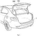
- FIG. 1 is a concept view showing an automatic safety tripod according to an embodiment of the present disclosure.
- FIG. 2 is a perspective view showing the automatic safety tripod according to the embodiment of the present disclosure.
- FIGS. 3A and 3B are sectional views showing a folded state and an unfolded state of the automatic safety tripod according to the embodiment of the present disclosure.
- FIG. 4 is a side sectional view showing the automatic safety tripod according to the embodiment of the present disclosure.
- FIGS. 5A and 5B are sectional views showing operational states of a display part of the automatic safety tripod according to the embodiment of the present disclosure.
- FIGS. 6A to 6C are views showing states of the automatic safety tripod mounted to a vehicle according to the embodiment of the present disclosure.
- the automatic safety tripod may include a frame 100 and a display part 200.
- the frame 100 may be formed in a long' ⁇ ' shape with one open surface.
- the display part 200 may protrude from the one open surface of the frame 100.
- the frame 100 may include a magnet (not shown) therein.
- the frame 100 may be attached and detached to a portion (e.g., trunk) in a vehicle 1 by the magnet (not shown) provided in the frame 100.
- the frame 100 may include a drive means 110 therein.
- the drive means 110 may operate folding and unfolding of the display part 200, may include a rotation bar 111, a motor 112, pulleys 113-1 and 113-2, and a wire 114.
- the rotation bar 111 may be provided in the frame 100 and be formed in a round rod shape.
- the rotation bar 111 may have screw threads 115 at opposite ends thereof.
- the screw threads 115 at opposite ends of the rotation bar 111 are coupled to a first support bar 231 and a second support bar 232. As the rotation bar 111 is rotated, the first support bar 231 and the second support bar 232 are rotated and moved along the screw threads 115 thus the display part 200 may be folded or unfolded.
- the motor 112 may be provided at a center portion of the rotation bar 111 and may rotate the rotation bar 111.
- the motor 112 may be a through-type motor provided to rotate the rotation bar 111 while being located at the center portion the rotation bar 111.
- the rotation bar 111 coupled to the motor 112 may be rotated by a rotary force of the motor 112.
- the pulleys 113-1 and 113-2 may be respectively provided in the frame 100 and at the rotation bar 111.
- the pulleys 113-1 provided at the inside portions of the frame 100 may allow the wire 114 to be efficiently released or wound.
- the pulleys 113-2 located at the rotation bar 111 may be coupled to the rotation bar 111 and be rotated by rotation of the rotation bar 111 so as to release or wind the wire 114.
- the pulleys 113-2 may be provided at opposite portions beside the motor 112 of the rotation bar 111.
- a second portion of the wire 114 may be connected to each of the pulleys 113-2 provided at the opposite portions of the motor 112.
- a first portion of the wire 114 may be connected to the first fixation bar 210 and a second portion of the wire 114 may be connected to each of the pulleys 113-2.
- the wire 114 may be wound or released by rotation of the pulleys 113-2. Therefore, as the wire 114 connected to each of the pulleys 113-2 is wound or released by rotation of the motor 112, the display part 200 may be folded or unfolded.
- the frame 100 may be formed in a cover (not shown) of which a part of a front surface is transparent in order to prevent the frame 100 from blocking the display part 200, for example, the frame 100 may be made of a material such as acrylic, plastic, etc.
- the display part 200 may be folded to be inserted into the frame 100 as a first portion thereof is coupled to the frame 100.
- the display part 200 may include the first fixation bar 210, a second fixation bar 220, the first support bar 231, the second support bar 232, a third support bag 233, and a fourth support bar 234.
- the first fixation bar 210 may include a pair of first and second guide grooves 211 and 212 at left and right side portions thereof.
- the third support bag 233 may be connected to the first guide groove 211.
- the fourth support bar 234 may be connected to the second guide groove 212.
- the first fixation bar 210 may be connected to the wire 114 and moved in vertical directions in response to winding or releasing of the wire 114.
- the second fixation bar 220 may be provided above the first fixation bar 210.
- a third guide groove 221 may be provided at a rear center portion of the second fixation bar 220, and a coupling member 236 of a support plate 235 slides along the third guide groove 221.
- the third guide groove 221 may be formed downwardly longer than the height of the second fixation bar 220.
- the second fixation bar 220 may have a hole 222 through which the wire 114 passes.
- Each of the first support bar 231, the second support bar 232, the third support bag 233, and the fourth support bar 234 may be formed in a bar shape with one saw-toothed end.
- the first support bar 231, the second support bar 232, the third support bag 233, and the fourth support bar 234 may be rotatably coupled to the support plate 235 so that the one portion of one of the support bars is coupled to other support bars close to the support bar.
- the support plate 235 may include the coupling member 236.
- the coupling member 236 may be coupled to the third guide groove 221 of the second fixation bar 220 and slide along the third guide groove 221.
- the first support bar 231 and the second support bar 232 may be respectively coupled, at second portions thereof, to the screw threads 115 of the rotation bar 111, and may be rotated by rotation of the rotation bar 111.
- the third support bag 233 and the fourth support bar 234 may be respectively coupled, at second portions thereof, to the first guide groove 211 and the second guide groove 212, and may slide along the first and second guide grooves 211 and 212.
- the first support bar 231, the second support bar 232, the third support bag 233, and the fourth support bar 234 may make an X-shape by saw-toothed portions thereof that are engaged with other support bars close to each other.
- the first fixation bar 210 of the display part 200 connected to the wire 114 may be moved.
- the first support bar 231, the second support bar 232, the third support bag 233, and the fourth support bar 234 of the display part 200 which are in a toothed-engaged state, may be unfolded or folded by a toothed-wheel mechanism.
- the display part 200 may include a plurality of LED lamps 250 on one surface. While the display part 200 is unfolded, the plurality of LED lamps 250 may be used to make a plurality of patterns. The plurality of LED lamps 250 may make the plurality of patterns under control of a controller 300. Furthermore, the plurality of LED lamps 250 may make the plurality of patterns by an operation part 500.
- the plurality of patterns may include an X-shaped pattern made by flashing the first support bar 231, the second support bar 232, the third support bag 233, and a triangle pattern made by flashing the fourth support bar 234, the third support bag 233, the fourth support bar 234, and the first fixation bar 210, and left and right arrow patterns made by flashing the first support bar 231, the second support bar 232, the third support bag 233, the fourth support bar 234, and the second fixation bar 220.
- the vehicle with the display part 200 may display emergency situations of the vehicle.
- the plurality of LED lamps 250 may be powered using a power line using a battery of the vehicle 1 or an inner battery.
- the inner battery (not shown) may be configured to be normally charged from the battery of the vehicle 1.
- the first fixation bar 210 is shown as a coupled state, but the present disclosure is not limited thereto.
- the first fixation bar 210 may be removably coupled to the third support bag 233 and the fourth support bar 234, and may be used even in a separated state.
- the first fixation bar 210 separated from the display part 200 may be formed in a rod shape, thereby being used as a rod-shaped emergency exit light.
- the automatic safety tripod of the present disclosure may be automatically unfolded or folded.
- FIG. 7 is a block diagram operating the display part of the automatic safety tripod according to the embodiment of the present disclosure.
- the automatic safety tripod may include the controller 300, a communication part 400, and the operation part 500.
- the controller 300 may be operationally connected to an emergency light or a shock detection unit of the vehicle 1 and control the display part 200.
- the controller 300 may operate the display part 200.
- the controller 300 may turn on the plurality of LED lamps 250 of the display part 200.
- the controller 300 may receive the operation signal of the operation part 500 from the communication part 400 and control the display part 200.
- the controller 300 may receive the operation signal of the operation part 500 and turn on the plurality of LED lamps 250 to make the triangle shape, X-shape, left and right arrowed shapes, etc.
- the controller 300 may control the plurality of LED lamps 250 to make the plurality of patterns to induce a lane change to a vehicle behind.
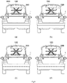
- FIGS. 8A to 8D are views showing operations of the display part of the automatic safety tripod according to the embodiment of the present disclosure.
- the display part 200 of the automatic safety tripod may make the plurality of patterns.
- the controller 300 may turn on the plurality of LED lamps 250 of the display part 200 to display the left and right shape, triangle shape, and X-shape.
- the plurality of LED lamps 250 may alternately flash in the X-shape and the left arrow shape so that an accident situation of the preceding vehicle is notified to a following vehicle and the following vehicle may be guided to change a lane. Furthermore, when the vehicle is stopped on a first lane on a road, the plurality of LED lamps 250 may alternately flash in the X-shape and the right arrow shape, so that an accident situation of the preceding vehicle may be notified to the following vehicle and the following vehicle may be guided to change a lane. Furthermore, the plurality of LED lamps 250 may alternately flash the X-shape and triangle shape, so that an accident situation of the preceding vehicle is notified to the following vehicle and may guide the following method to slow down.
- the communication part 400 may be provided in the frame 100.
- the communication part 400 may receive the operation signal of the operation part by the operation of the user.
- the communication part 400 may communicate with the operation part 500 wirelessly.
- the wireless communication may be realized by using a known communication method capable of transmitting a signal in a short distance such as Bluetooth ® , Zigbee ® , infra-red, etc.
- the communication part 400 and the operation part 500 are connected to each other by the wireless communication, but the present disclosure is not limited thereto.
- the communication part 400 and the operation part 500 may be connected to each other by power supply line, signal transmission line, etc., in order to realize power supply and transmission of the operation signal.
- the operation part 500 may generate the operation signal in order to control the display part 200 by operation of the user.
- the operation signal may receive a turning mode (e.g., flashing method, color change, brightness change, etc.), operation mode, etc. of the display part 200.
- the operation part 500 may be directly provided in the frame 100.
- the operation part 500 may be a remote control provided to remotely transmit the operation signal, and may be directly installed in the vehicle.
- the safety tripod may be provided in the vehicle and automatically unfolded at a rear end of the vehicle in an emergency situation, so that a following vehicle may recognize a sudden stop of the preceding vehicle and avoid an accident.
- the vehicle with tripod may be easily identified even in environment where it is difficult to secure driving visibility at night and in fog.
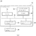
- FIG. 9 is a block diagram showing computing environment including a computing device suitable for use in exemplary embodiments.
- each component may have different function and ability other than those described below, and the present disclosure may include additional components in addition to those described below.
- Computing environment 10 shown in the drawing includes a computing device 12.
- the computing device 12 may be the controller 300.
- the computing device 12 may be the operation part 500.
- the computing device 12 may include at least one processor 14, one computer readable storage medium 16, and one communication bus 18.
- the processor 14 may allow the computing device 12 to be operated according to the above-described exemplary embodiment.
- the processor 14 may execute at least one program stored in the computer readable storage medium 16.
- the at least one program may include at least one computer executable instruction.
- the computer executable instruction may allow the computing device 12 to execute the operations according to the exemplary embodiment.
- the computer readable storage medium 16 may be configured to store computer executable instruction or a program code, and program data and/or other suitably formed information.
- the program 20 stored in the computer readable storage medium 16 may include a group of instructions executable by the processor 14.
- the computer readable storage medium 16 may be a memory (nonvolatile memory such as random access memory, volatile memory, or appropriate complex thereof), at least one magnetic disk storage device, optical disk storage devices, flash memory devices, differently formed storage medium capable of accessing and storing desired information by the computing device 12, or an appropriate complex thereof.
- the communication bus 18 may relatively connect other various components of the computing device 12 to each other in addition to the processor 14, the computer readable storage medium 16.
- the computing device 12 may include at least one input and output interface 22 that provides an interface for at least one input and output device 24 and at least one network communication interface 26. Both the input and output interface 22 and the network communication interface 26 are connected to the communication bus 18.
- the input and output device 24 may be connected to other components of the computing device 12 through the input and output interface 22.
- the input and output device 24 may include a pointing device (mouse track pad, or the like), a keyboard, a touchable input device (touch pad, touch screen, or the like), a voice or sound input device, various types of sensor devices and/or input devices such as a capturing device, and/or an output device such as a display device, a printer, a speaker, and/or a network card.
- the input and output device 24 may be included in the computing device 12 as one component constituting the computing device 12, and may be connected to the computing device 12 as a separate device from the computing device 12.
Landscapes
- Engineering & Computer Science (AREA)
- Mechanical Engineering (AREA)
- General Engineering & Computer Science (AREA)
- Physics & Mathematics (AREA)
- General Physics & Mathematics (AREA)
- Theoretical Computer Science (AREA)
- Lighting Device Outwards From Vehicle And Optical Signal (AREA)
- Road Signs Or Road Markings (AREA)
Abstract
Description
- The present disclosure relates to an automatic safety tripod for a vehicle.
- In general, while driving a car, not only safety accidents but also emergency situations that are not related to the intention of a driver frequently occur. In order to protect the driver and passengers from the accidents and to inform the driver and the passengers of the emergency situation, it is stipulated by law that a safety tripod for a vehicle is mandatory.
- The safety tripod for a vehicle is manufactured in a triangular shape in accordance with relevant law and regulation, and is manufactured by attaching a light reflecting plate or a reflecting film on a surface to reduce a unit cost. In article 40 of the enforcement rule of the road traffic act, it is stipulated that a safety tripod is installed at a distance of 100m or more from a broken or accident vehicle on a highway or an exclusive road for automobiles.
- However, in setting up the conventional safety tripod, it is difficult to quickly setting up the safety tripod due to time consuming for releasing a support and putting the tripod together. Therefore, a driver is reluctant to set up a safety tripod, and secondary accidents due to the time consuming for setting the safety tripod and secondary traffic accidents due to non-setting of the safety tripod may increase. Furthermore, the conventional safety tripod for a vehicle is formed in a fixedly-formed triangular shape and may have a problem of reducing storage performance of a storage space of a vehicle.
- Accordingly, the present disclosure is intended to provide an automatic safety tripod configured to be stored without a separate space while being foldable when being mounted and stored in a vehicle.
- Another objective of the present disclosure is intended to provide an automatic safety tripod configured to be automatically unfolded at a rear end of a vehicle in an emergency situation while being mounted in the vehicle.
- In order to achieve the above objective, according to one aspect of the present disclosure, there is provided an automatic safety tripod for a vehicle, the automatic safety tripod including: a frame formed in a housing with one open surface; and a display part of which one portion may be connected to the frame, the display part being configured to be folded to be inserted into the frame or to be unfolded to protrude out of the frame, wherein the frame may include: a rotation bar provided in the frame, and having screw threads at opposite ends thereof, the screw threads being screwed to one side of the frame; a motor provided at a center portion of the rotation bar and configured to rotate the rotation bar; pulleys respectively provided at opposite sides of the rotation bar based on the center portion; and a wire of which a first portion may be connected to each of the pulleys and a second portion may be connected to the display part, the wire being configured to move the frame by rotation of the pulley.
- The display part may include: a first fixation bar having a first guide groove and a second guide groove, the first guide groove and the second guide groove being located at left and right portions of a side surface thereof; a second fixation bar located above the first fixation bar; a plurality of support plates having saw-toothed first ends, each of the saw-toothed first ends being rotatably coupled to each of the support plates and the supports plates located adjacent to each other being engaged by the saw-toothed first ends thereof, the plurality of support plates having second ends respectively connected to the screw threads, the first guide groove, and the second guide groove, wherein the plurality of support plates may include: a first support bar and a second support bar of which second portions are coupled to the screw threads, and configured to be moved along the screw threads; a third support bar of which a second portion may be coupled to the first guide groove, and configured to be moved along the first guide groove; and a fourth support bar of which a second portion may be coupled to the second guide groove, and configured to be moved along the second guide groove.
- The display part may include: a plurality of LED lamps provided on one surface thereof, the automatic safety tripod further including: an operation part configured to generate an operation signal by manipulation of a user so as to operation a flashing mode of the display part; and a controller configured to receive the operation signal and to control flash of the plurality of LED lamps so as to make a plurality of patterns, wherein the plurality of patterns may include: an x-pattern made by flashing the first support bar, the second support bar, the third support bag, and the fourth support bar, a triangle pattern made by flashing the third support bag, the fourth support bar, and the first fixation bar, and left and right arrow patterns made by flashing the first support bar, the second support bar, the third support bag, the fourth support bar, and the second fixation bar.
- According to the embodiments of the present disclosure, when the safety tripod is mounted and stored in the vehicle, the safety tripod is configured to be foldable, so that the safety tripod can be stored without occupying a large space.
- According to the embodiments of the present disclosure, the safety tripod is provided in the vehicle and automatically unfolded from a rear end of the vehicle in an emergency situation, so that a following vehicle can recognize a sudden stop of the preceding vehicle and prevent an accident.
- According to the embodiments of the present disclosure, in an emergency situation on a highway where vehicles are traveling at high speed, a user can safely set up the safety tripod while driving without getting off and turn on the LED lamps while setting up the safety tripod, so that the vehicle with the safety tripod can be easily identified even in environment where it is difficult to secure driving visibility at night and in fog.
- The above and other objectives, features, and other advantages of the present disclosure will be more clearly understood from the subsequent detailed description when taken in conjunction with the accompanying drawings, in which:
-
FIG. 1 is a concept view showing an automatic safety tripod according to an embodiment of the present disclosure; -
FIG. 2 is a perspective view showing the automatic safety tripod according to the embodiment of the present disclosure; -
FIGS. 3A and 3B are sectional views showing a folded state and an unfolded state of the automatic safety tripod according to the embodiment of the present disclosure; -
FIG. 4 is a side sectional view showing the automatic safety tripod according to the embodiment of the present disclosure; -
FIGS. 5A and 5B are sectional views showing operational states of a display part of the automatic safety tripod according to the embodiment of the present disclosure; -
FIGS. 6A to 6C are views showing states of the automatic safety tripod mounted to a vehicle according to the embodiment of the present disclosure; -
FIG. 7 is a block diagram operating the display part of the automatic safety tripod according to the embodiment of the present disclosure; -
FIGS. 8A to 8D are views showing operations of the display part of the automatic safety tripod according to the embodiment of the present disclosure; and -
FIG. 9 is a block diagram showing computing environment including a computing device suitable for use in exemplary embodiments. -
- 100 :
- frame
- 110 :
- drive means
- 111 :
- rotation bar
- 112 :
- motor
- 113-1, 113-2 :
- pulleys
- 114:
- wire
- 200 :
- display part
- 210 :
- first fixation bar
- 211 :
- first guide groove
- 212 :
- second guide groove
- 220 :
- second fixation bar
- 221 :
- third guide groove
- 231 :
- first support bar
- 232 :
- second support bar
- 233 :
- third support bar
- 234 :
- fourth support bar
- 235 :
- support plate
- 236 :
- coupling member
- 250 :
- LED lamps
- 300 :
- controller
- 400:
- communication part
- 500:
- operation part
- Hereinbelow, an exemplary embodiment of the present disclosure will be described with reference to accompanying drawings. The following detailed description of the present disclosure is presented to representative for purposes of helping more comprehensive understanding of the methods, devices, and systems described herein. However, this is only an example and the present disclosure is not limited thereto.
- In the following description, it is to be noted that when the functions of conventional elements and the detailed description of elements related with the present disclosure may make the gist of the present disclosure unclear a detailed description of those elements will be omitted. Terms to be described later are defined in consideration of functions in the present disclosure, which may vary according to intentions or customs of users and operators. Therefore, the definition thereof should be made based on the content throughout this specification. The terminology used herein is for the purpose of describing particular embodiments only and is not intended to be limiting. As used herein, the singular forms "a", "an" and "the" are intended to include the plural forms as well, unless the context clearly indicates otherwise. It will be further understood that the terms "comprise", "include", "have", etc. when used in this specification, specify the presence of stated features, integers, steps, operations, elements, components, and/or combinations of them but do not preclude the presence or addition of one or more other features, integers, steps, operations, elements, components, and/or combinations thereof.
- The relative terms such as "below", "above", "upper", "lower", "horizontal", and "vertical" may be used to describe a relationship between different members, layers, or regions in this specification. It should be collectively understood such that these terms mean directions marked in the drawings as well as directions of other devices.
-
FIG. 1 is a concept view showing an automatic safety tripod according to an embodiment of the present disclosure.FIG. 2 is a perspective view showing the automatic safety tripod according to the embodiment of the present disclosure.FIGS. 3A and 3B are sectional views showing a folded state and an unfolded state of the automatic safety tripod according to the embodiment of the present disclosure.FIG. 4 is a side sectional view showing the automatic safety tripod according to the embodiment of the present disclosure.FIGS. 5A and 5B are sectional views showing operational states of a display part of the automatic safety tripod according to the embodiment of the present disclosure.FIGS. 6A to 6C are views showing states of the automatic safety tripod mounted to a vehicle according to the embodiment of the present disclosure. - As shown in
FIGS. 1 to 6C , the automatic safety tripod according to the embodiment of the present disclosure may include aframe 100 and adisplay part 200. - The
frame 100 may be formed in a long'⊂' shape with one open surface. Thedisplay part 200 may protrude from the one open surface of theframe 100. Theframe 100 may include a magnet (not shown) therein. Theframe 100 may be attached and detached to a portion (e.g., trunk) in avehicle 1 by the magnet (not shown) provided in theframe 100. - The
frame 100 may include a drive means 110 therein. The drive means 110 may operate folding and unfolding of thedisplay part 200, may include arotation bar 111, amotor 112, pulleys 113-1 and 113-2, and awire 114. - The
rotation bar 111 may be provided in theframe 100 and be formed in a round rod shape. Therotation bar 111 may havescrew threads 115 at opposite ends thereof. Thescrew threads 115 at opposite ends of therotation bar 111 are coupled to afirst support bar 231 and asecond support bar 232. As therotation bar 111 is rotated, thefirst support bar 231 and thesecond support bar 232 are rotated and moved along thescrew threads 115 thus thedisplay part 200 may be folded or unfolded. - The
motor 112 may be provided at a center portion of therotation bar 111 and may rotate therotation bar 111. For example, themotor 112 may be a through-type motor provided to rotate therotation bar 111 while being located at the center portion therotation bar 111. Therotation bar 111 coupled to themotor 112 may be rotated by a rotary force of themotor 112. - The pulleys 113-1 and 113-2 may be respectively provided in the
frame 100 and at therotation bar 111. The pulleys 113-1 provided at the inside portions of theframe 100 may allow thewire 114 to be efficiently released or wound. Furthermore, the pulleys 113-2 located at therotation bar 111 may be coupled to therotation bar 111 and be rotated by rotation of therotation bar 111 so as to release or wind thewire 114. The pulleys 113-2 may be provided at opposite portions beside themotor 112 of therotation bar 111. A second portion of thewire 114 may be connected to each of the pulleys 113-2 provided at the opposite portions of themotor 112. A first portion of thewire 114 may be connected to thefirst fixation bar 210 and a second portion of thewire 114 may be connected to each of the pulleys 113-2. Thewire 114 may be wound or released by rotation of the pulleys 113-2. Therefore, as thewire 114 connected to each of the pulleys 113-2 is wound or released by rotation of themotor 112, thedisplay part 200 may be folded or unfolded. - Meanwhile, in the embodiment, it is shown that four pulleys are included in the
frame 100, but the present disclosure is not limited thereto, and two pulleys may be included in theframe 100. - Furthermore, the
frame 100 may be formed in a cover (not shown) of which a part of a front surface is transparent in order to prevent theframe 100 from blocking thedisplay part 200, for example, theframe 100 may be made of a material such as acrylic, plastic, etc. - The
display part 200 may be folded to be inserted into theframe 100 as a first portion thereof is coupled to theframe 100. Thedisplay part 200 may include thefirst fixation bar 210, asecond fixation bar 220, thefirst support bar 231, thesecond support bar 232, athird support bag 233, and afourth support bar 234. - The
first fixation bar 210 may include a pair of first andsecond guide grooves third support bag 233 may be connected to thefirst guide groove 211. Thefourth support bar 234 may be connected to thesecond guide groove 212. Thefirst fixation bar 210 may be connected to thewire 114 and moved in vertical directions in response to winding or releasing of thewire 114. - The
second fixation bar 220 may be provided above thefirst fixation bar 210. Athird guide groove 221 may be provided at a rear center portion of thesecond fixation bar 220, and acoupling member 236 of asupport plate 235 slides along thethird guide groove 221. Thethird guide groove 221 may be formed downwardly longer than the height of thesecond fixation bar 220. When thedisplay part 200 is folded, thecoupling member 236 is moved downward along thethird guide groove 221 and thefirst fixation bar 210 and thesecond fixation bar 220 may be fully inserted into theframe 100. - Furthermore, the
second fixation bar 220 may have ahole 222 through which thewire 114 passes. Thesecond fixation bar 220 may maintain a straight shape ('-' shape) thereof by thecoupling member 236 and the wire 113, and may maintain a parallel shape ('=' shape) by being maintained in parallel to thefirst fixation bar 210. - Each of the
first support bar 231, thesecond support bar 232, thethird support bag 233, and thefourth support bar 234 may be formed in a bar shape with one saw-toothed end. Thefirst support bar 231, thesecond support bar 232, thethird support bag 233, and thefourth support bar 234 may be rotatably coupled to thesupport plate 235 so that the one portion of one of the support bars is coupled to other support bars close to the support bar. Thesupport plate 235 may include thecoupling member 236. Thecoupling member 236 may be coupled to thethird guide groove 221 of thesecond fixation bar 220 and slide along thethird guide groove 221. Thefirst support bar 231 and thesecond support bar 232 may be respectively coupled, at second portions thereof, to thescrew threads 115 of therotation bar 111, and may be rotated by rotation of therotation bar 111. Thethird support bag 233 and thefourth support bar 234 may be respectively coupled, at second portions thereof, to thefirst guide groove 211 and thesecond guide groove 212, and may slide along the first andsecond guide grooves - When the
display part 200 is unfolded, thefirst support bar 231, thesecond support bar 232, thethird support bag 233, and thefourth support bar 234 may make an X-shape by saw-toothed portions thereof that are engaged with other support bars close to each other. - As the
rotation bar 111 is rotated by themotor 112, thefirst fixation bar 210 of thedisplay part 200 connected to thewire 114 may be moved. In addition, as thefirst support bar 231 and thesecond support bar 232 connected to thescrew threads 115 are moved, thefirst support bar 231, thesecond support bar 232, thethird support bag 233, and thefourth support bar 234 of thedisplay part 200, which are in a toothed-engaged state, may be unfolded or folded by a toothed-wheel mechanism. - Furthermore, the
display part 200 may include a plurality ofLED lamps 250 on one surface. While thedisplay part 200 is unfolded, the plurality ofLED lamps 250 may be used to make a plurality of patterns. The plurality ofLED lamps 250 may make the plurality of patterns under control of acontroller 300. Furthermore, the plurality ofLED lamps 250 may make the plurality of patterns by anoperation part 500. The plurality of patterns may include an X-shaped pattern made by flashing thefirst support bar 231, thesecond support bar 232, thethird support bag 233, and a triangle pattern made by flashing thefourth support bar 234, thethird support bag 233, thefourth support bar 234, and thefirst fixation bar 210, and left and right arrow patterns made by flashing thefirst support bar 231, thesecond support bar 232, thethird support bag 233, thefourth support bar 234, and thesecond fixation bar 220. - As described above, as the
display part 200 makes the X-shaped pattern, the triangle pattern, the left and right arrow patterns, etc. by using the plurality ofLED lamps 250, the vehicle with thedisplay part 200 may display emergency situations of the vehicle. The plurality ofLED lamps 250 may be powered using a power line using a battery of thevehicle 1 or an inner battery. The inner battery (not shown) may be configured to be normally charged from the battery of thevehicle 1. - Meanwhile, in the embodiment, the
first fixation bar 210 is shown as a coupled state, but the present disclosure is not limited thereto. Thefirst fixation bar 210 may be removably coupled to thethird support bag 233 and thefourth support bar 234, and may be used even in a separated state. For example, thefirst fixation bar 210 separated from thedisplay part 200 may be formed in a rod shape, thereby being used as a rod-shaped emergency exit light. - As a result, as shown in
FIG. 6 , the automatic safety tripod of the present disclosure may be automatically unfolded or folded. -
FIG. 7 is a block diagram operating the display part of the automatic safety tripod according to the embodiment of the present disclosure. - As shown in
FIG. 7 , the automatic safety tripod according to the embodiment of the present disclosure may include thecontroller 300, acommunication part 400, and theoperation part 500. - The
controller 300 may be operationally connected to an emergency light or a shock detection unit of thevehicle 1 and control thedisplay part 200. When the emergency light of thevehicle 1 remains for a certain period of time or the shock detection unit transmits a shock detection signal, thecontroller 300 may operate thedisplay part 200. Thecontroller 300 may turn on the plurality ofLED lamps 250 of thedisplay part 200. - Furthermore, the
controller 300 may receive the operation signal of theoperation part 500 from thecommunication part 400 and control thedisplay part 200. Thecontroller 300 may receive the operation signal of theoperation part 500 and turn on the plurality ofLED lamps 250 to make the triangle shape, X-shape, left and right arrowed shapes, etc. - The
controller 300 may control the plurality ofLED lamps 250 to make the plurality of patterns to induce a lane change to a vehicle behind. -
FIGS. 8A to 8D are views showing operations of the display part of the automatic safety tripod according to the embodiment of the present disclosure. - As shown in
FIG. 8 , thedisplay part 200 of the automatic safety tripod may make the plurality of patterns. Thecontroller 300 may turn on the plurality ofLED lamps 250 of thedisplay part 200 to display the left and right shape, triangle shape, and X-shape. - For example, when the vehicle is stopped on a right side lane on a road, the plurality of
LED lamps 250 may alternately flash in the X-shape and the left arrow shape so that an accident situation of the preceding vehicle is notified to a following vehicle and the following vehicle may be guided to change a lane. Furthermore, when the vehicle is stopped on a first lane on a road, the plurality ofLED lamps 250 may alternately flash in the X-shape and the right arrow shape, so that an accident situation of the preceding vehicle may be notified to the following vehicle and the following vehicle may be guided to change a lane. Furthermore, the plurality ofLED lamps 250 may alternately flash the X-shape and triangle shape, so that an accident situation of the preceding vehicle is notified to the following vehicle and may guide the following method to slow down. - Referring to
FIG. 7 , thecommunication part 400 may be provided in theframe 100. Thecommunication part 400 may receive the operation signal of the operation part by the operation of the user. Thecommunication part 400 may communicate with theoperation part 500 wirelessly. The wireless communication may be realized by using a known communication method capable of transmitting a signal in a short distance such as Bluetooth®, Zigbee®, infra-red, etc. - Meanwhile, in the embodiment, it is shown that the
communication part 400 and theoperation part 500 are connected to each other by the wireless communication, but the present disclosure is not limited thereto. In addition, thecommunication part 400 and theoperation part 500 may be connected to each other by power supply line, signal transmission line, etc., in order to realize power supply and transmission of the operation signal. - The
operation part 500 may generate the operation signal in order to control thedisplay part 200 by operation of the user. The operation signal may receive a turning mode (e.g., flashing method, color change, brightness change, etc.), operation mode, etc. of thedisplay part 200. Theoperation part 500 may be directly provided in theframe 100. Furthermore, theoperation part 500 may be a remote control provided to remotely transmit the operation signal, and may be directly installed in the vehicle. - Therefore, the safety tripod may be provided in the vehicle and automatically unfolded at a rear end of the vehicle in an emergency situation, so that a following vehicle may recognize a sudden stop of the preceding vehicle and avoid an accident.
- Furthermore, in an emergency situation on a highway where vehicles are traveling at high speed, a user can safely set up the safety tripod while driving without getting off. As the LED lamps are turned on while setting up the safety tripod, the vehicle with tripod may be easily identified even in environment where it is difficult to secure driving visibility at night and in fog.
-
FIG. 9 is a block diagram showing computing environment including a computing device suitable for use in exemplary embodiments. In the embodiment shown inFIG. 9 , each component may have different function and ability other than those described below, and the present disclosure may include additional components in addition to those described below. -
Computing environment 10 shown in the drawing includes acomputing device 12. In the embodiment, thecomputing device 12 may be thecontroller 300. Furthermore, thecomputing device 12 may be theoperation part 500. - The
computing device 12 may include at least oneprocessor 14, one computerreadable storage medium 16, and onecommunication bus 18. Theprocessor 14 may allow thecomputing device 12 to be operated according to the above-described exemplary embodiment. For example, theprocessor 14 may execute at least one program stored in the computerreadable storage medium 16. The at least one program may include at least one computer executable instruction. When theprocessor 14 executes the computer executable instruction, the computer executable instruction may allow thecomputing device 12 to execute the operations according to the exemplary embodiment. - The computer
readable storage medium 16 may be configured to store computer executable instruction or a program code, and program data and/or other suitably formed information. Theprogram 20 stored in the computerreadable storage medium 16 may include a group of instructions executable by theprocessor 14. In the embodiment, the computerreadable storage medium 16 may be a memory (nonvolatile memory such as random access memory, volatile memory, or appropriate complex thereof), at least one magnetic disk storage device, optical disk storage devices, flash memory devices, differently formed storage medium capable of accessing and storing desired information by thecomputing device 12, or an appropriate complex thereof. - The
communication bus 18 may relatively connect other various components of thecomputing device 12 to each other in addition to theprocessor 14, the computerreadable storage medium 16. - The
computing device 12 may include at least one input andoutput interface 22 that provides an interface for at least one input andoutput device 24 and at least onenetwork communication interface 26. Both the input andoutput interface 22 and thenetwork communication interface 26 are connected to thecommunication bus 18. The input andoutput device 24 may be connected to other components of thecomputing device 12 through the input andoutput interface 22. For example, the input andoutput device 24 may include a pointing device (mouse track pad, or the like), a keyboard, a touchable input device (touch pad, touch screen, or the like), a voice or sound input device, various types of sensor devices and/or input devices such as a capturing device, and/or an output device such as a display device, a printer, a speaker, and/or a network card. For example, the input andoutput device 24 may be included in thecomputing device 12 as one component constituting thecomputing device 12, and may be connected to thecomputing device 12 as a separate device from thecomputing device 12. - Although the preferred embodiment of the present disclosure has been disclosed for illustrative purposes, those skilled in the art will appreciate that various modifications, additions and substitutions are possible, without departing from the scope and spirit of the present disclosure as disclosed in the accompanying claims. It is thus well known to those skilled in that art that the present disclosure is not limited to the embodiment disclosed in the detailed description, and the patent right of the present disclosure should be defined by the scope and spirit of the present disclosure as disclosed in the accompanying claims. Accordingly, it should be understood that the present disclosure includes various modifications, additions and substitutions without departing from the scope and spirit of the present disclosure as disclosed in the accompanying claims.
Claims (3)
- An automatic safety tripod for a vehicle, the automatic safety tripod comprising:a frame formed in a housing with one open surface; anda display part of which one portion is connected to the frame, the display part being configured to be folded to be inserted into the frame or to be unfolded to protrude out of the frame,wherein the frame comprises:a rotation bar provided in the frame, and having screw threads at opposite ends thereof, the screw threads being screwed to one side of the frame;a motor provided at a center portion of the rotation bar and configured to rotate the rotation bar;pulleys respectively provided at opposite sides of the rotation bar based on the center portion; anda wire of which a first portion is connected to each of the pulleys and a second portion is connected to the display part, the wire being configured to move the frame by rotation of the pulley.
- The automatic safety tripod of claim 1, wherein the display part comprises:a first fixation bar having a first guide groove and a second guide groove, the first guide groove and the second guide groove being located at left and right portions of a side surface thereof;a second fixation bar located above the first fixation bar;a plurality of support plates having saw-toothed first ends, each of the saw-toothed first ends being rotatably coupled to each of the support plates and the supports plates located adj acent to each other being engaged by the saw-toothed first ends thereof, the plurality of support plates having second ends respectively connected to the screw threads, the first guide groove, and the second guide groove,wherein the plurality of support plates comprises:a first support bar and a second support bar of which second portions are coupled to the screw threads, and configured to be moved along the screw threads;a third support bar of which a second portion is coupled to the first guide groove, and configured to be moved along the first guide groove; anda fourth support bar of which a second portion is coupled to the second guide groove, and configured to be moved along the second guide groove.
- The automatic safety tripod of claim 2, wherein the display part comprises:a plurality of LED lamps provided on one surface thereof,the automatic safety tripod further comprising:an operation part configured to generate an operation signal by manipulation of a user so as to operation a flashing mode of the display part; anda controller configured to receive the operation signal and to control flash of the plurality of LED lamps so as to make a plurality of patterns,wherein the plurality of patterns comprises:
an x-pattern made by flashing the first support bar, the second support bar, the third support bag, and the fourth support bar, a triangle pattern made by flashing the third support bag, the fourth support bar, and the first fixation bar, and left and right arrow patterns made by flashing the first support bar, the second support bar, the third support bag, the fourth support bar, and the second fixation bar.
Applications Claiming Priority (2)
| Application Number | Priority Date | Filing Date | Title |
|---|---|---|---|
| KR1020190077913A KR102223899B1 (en) | 2019-06-28 | 2019-06-28 | Automatic Safety Tripod of Vehicles |
| PCT/KR2020/007891 WO2020262883A1 (en) | 2019-06-28 | 2020-06-18 | Automatic safety tripod for vehicle |
Publications (2)
| Publication Number | Publication Date |
|---|---|
| EP3978313A1 true EP3978313A1 (en) | 2022-04-06 |
| EP3978313A4 EP3978313A4 (en) | 2022-08-24 |
Family
ID=74061892
Family Applications (1)
| Application Number | Title | Priority Date | Filing Date |
|---|---|---|---|
| EP20832579.5A Withdrawn EP3978313A4 (en) | 2019-06-28 | 2020-06-18 | AUTOMATIC SAFETY TRIPOD FOR ONE VEHICLE |
Country Status (6)
| Country | Link |
|---|---|
| US (1) | US11731553B2 (en) |
| EP (1) | EP3978313A4 (en) |
| JP (1) | JP7370398B2 (en) |
| KR (1) | KR102223899B1 (en) |
| CN (1) | CN218986474U (en) |
| WO (1) | WO2020262883A1 (en) |
Cited By (1)
| Publication number | Priority date | Publication date | Assignee | Title |
|---|---|---|---|---|
| EP4324702A4 (en) * | 2021-04-15 | 2025-04-09 | INDURAS, iNC. | Automatically deployed tripod for vehicle |
Families Citing this family (4)
| Publication number | Priority date | Publication date | Assignee | Title |
|---|---|---|---|---|
| KR102704059B1 (en) * | 2021-04-15 | 2024-09-06 | 임병언 | Automatic spread tripod for vehicle |
| KR102557387B1 (en) | 2021-10-15 | 2023-07-18 | 임병언 | Auto safety tripod for vehicle |
| KR102691158B1 (en) * | 2023-03-10 | 2024-08-05 | 대훈 데이비드 진 | Dynamic escape path direction system |
| TWI915139B (en) | 2024-12-20 | 2026-02-11 | 百盈實業股份有限公司 | Warning light device |
Family Cites Families (13)
| Publication number | Priority date | Publication date | Assignee | Title |
|---|---|---|---|---|
| JPS602025Y2 (en) * | 1980-01-26 | 1985-01-21 | 森尾電機株式会社 | Vehicle-mounted marking device |
| US5041813A (en) * | 1990-01-25 | 1991-08-20 | Chang Jih Cheng | "Automobile disabled" sign |
| KR20050054179A (en) * | 2003-12-04 | 2005-06-10 | 이광성 | A road safety indicator |
| KR200414174Y1 (en) | 2005-11-22 | 2006-04-18 | 신대철 | Tubular Safety Tripod |
| CN201077419Y (en) * | 2007-06-20 | 2008-06-25 | 覃华东 | Up-down alarm indication marks |
| KR101251037B1 (en) | 2010-11-11 | 2013-04-05 | 손상석 | Triangular warning device for installing in car |
| US9243787B2 (en) | 2012-10-28 | 2016-01-26 | Measurement Ltd. | Automotive safety device |
| TW201738853A (en) | 2016-04-26 | 2017-11-01 | 鴻海精密工業股份有限公司 | Vehicle warning system and method |
| KR101686816B1 (en) | 2016-08-25 | 2016-12-15 | 이장수 | Apparatus For Installing Emergency tripod |
| KR20180031563A (en) * | 2016-09-19 | 2018-03-28 | 김재복 | The vehicle automatic unfolding emergency notification apparatus and method |
| US11382422B1 (en) * | 2019-02-25 | 2022-07-12 | Frank Gatski | Overhead storage system and apparatus configured to raise and lower |
| NL2024420B1 (en) * | 2019-12-10 | 2021-08-31 | Axiturn B V | Foldable solar panel assembly |
| CA3175657A1 (en) * | 2020-04-20 | 2021-10-28 | Jonathan I. Kaplan | Christmas tree and method of assembling a tree |
-
2019
- 2019-06-28 KR KR1020190077913A patent/KR102223899B1/en active Active
-
2020
- 2020-06-18 US US17/618,424 patent/US11731553B2/en active Active
- 2020-06-18 JP JP2021573359A patent/JP7370398B2/en active Active
- 2020-06-18 CN CN202090000613.4U patent/CN218986474U/en active Active
- 2020-06-18 EP EP20832579.5A patent/EP3978313A4/en not_active Withdrawn
- 2020-06-18 WO PCT/KR2020/007891 patent/WO2020262883A1/en not_active Ceased
Cited By (1)
| Publication number | Priority date | Publication date | Assignee | Title |
|---|---|---|---|---|
| EP4324702A4 (en) * | 2021-04-15 | 2025-04-09 | INDURAS, iNC. | Automatically deployed tripod for vehicle |
Also Published As
| Publication number | Publication date |
|---|---|
| EP3978313A4 (en) | 2022-08-24 |
| US11731553B2 (en) | 2023-08-22 |
| KR102223899B1 (en) | 2021-03-04 |
| KR20210001599A (en) | 2021-01-06 |
| JP7370398B2 (en) | 2023-10-27 |
| JP2022536674A (en) | 2022-08-18 |
| US20220250538A1 (en) | 2022-08-11 |
| CN218986474U (en) | 2023-05-09 |
| WO2020262883A1 (en) | 2020-12-30 |
Similar Documents
| Publication | Publication Date | Title |
|---|---|---|
| US11731553B2 (en) | Automatic safety tripod for vehicle | |
| JP7098031B2 (en) | vehicle | |
| US7825790B2 (en) | Emergency vehicle light bar with message display | |
| EP3107799B1 (en) | Lighting device for an at least partially muscle driven vehicle by means of light guide elements | |
| US9843734B2 (en) | Retractable camera for vehicle | |
| KR101772444B1 (en) | Projection type virtual safety tripod display apparatus for vehicle | |
| KR101932959B1 (en) | Vehicle Emergency notification device for prevention of secondary accident and its method | |
| KR101449662B1 (en) | Car Emergency Condition Mark System | |
| KR101097001B1 (en) | Crosswalk street lights to prevent vehicle accidents | |
| KR102406011B1 (en) | Vehicle Information External Display System and Vehicle thereof | |
| US10994652B2 (en) | Emergency notification device for vehicle and rear vehicle assistance system including same | |
| KR20120020887A (en) | A remotely installable warning triangle for a vehicle | |
| JP2017537030A (en) | One-touch safety triangle display | |
| KR101654228B1 (en) | Self propelled type electronic sign board | |
| KR200480975Y1 (en) | Apparatus for controlling Traffic safety sign and control system thereof | |
| KR102704059B1 (en) | Automatic spread tripod for vehicle | |
| KR20220073348A (en) | System for dealing with traffic accident by using internet of things warning triangle | |
| US20190366962A1 (en) | Safety barrier device and system and methods for using same | |
| JP7606786B2 (en) | Automatic deployment triangle for vehicles | |
| KR102105426B1 (en) | A safety equipment for pedestrian of school zone | |
| CN221049584U (en) | Automatic deployable tripod for vehicles | |
| KR101663182B1 (en) | Apparatus for controlling Traffic safety sign and method thereof | |
| KR102915970B1 (en) | Warning triangle installed in vehicle headliner | |
| KR101942317B1 (en) | Safty tripod attachable car's trunk with siginal light | |
| KR20200085666A (en) | Also Used as a traffic signal Protective case of Vehicle notification device |
Legal Events
| Date | Code | Title | Description |
|---|---|---|---|
| STAA | Information on the status of an ep patent application or granted ep patent |
Free format text: STATUS: THE INTERNATIONAL PUBLICATION HAS BEEN MADE |
|
| PUAI | Public reference made under article 153(3) epc to a published international application that has entered the european phase |
Free format text: ORIGINAL CODE: 0009012 |
|
| STAA | Information on the status of an ep patent application or granted ep patent |
Free format text: STATUS: REQUEST FOR EXAMINATION WAS MADE |
|
| 17P | Request for examination filed |
Effective date: 20211229 |
|
| AK | Designated contracting states |
Kind code of ref document: A1 Designated state(s): AL AT BE BG CH CY CZ DE DK EE ES FI FR GB GR HR HU IE IS IT LI LT LU LV MC MK MT NL NO PL PT RO RS SE SI SK SM TR |
|
| A4 | Supplementary search report drawn up and despatched |
Effective date: 20220722 |
|
| RIC1 | Information provided on ipc code assigned before grant |
Ipc: B60Q 1/50 20060101ALI20220718BHEP Ipc: F16H 1/20 20060101ALI20220718BHEP Ipc: F16H 21/12 20060101ALI20220718BHEP Ipc: B60Q 1/26 20060101ALI20220718BHEP Ipc: B60Q 1/30 20060101ALI20220718BHEP Ipc: B60Q 1/52 20060101ALI20220718BHEP Ipc: B60Q 7/00 20060101AFI20220718BHEP |
|
| DAV | Request for validation of the european patent (deleted) | ||
| DAX | Request for extension of the european patent (deleted) | ||
| RAP1 | Party data changed (applicant data changed or rights of an application transferred) |
Owner name: INDURAS, INC. |
|
| RIN1 | Information on inventor provided before grant (corrected) |
Inventor name: THE INVENTOR HAS WAIVED HIS RIGHT TO BE THUS MENTIONED. |
|
| STAA | Information on the status of an ep patent application or granted ep patent |
Free format text: STATUS: THE APPLICATION IS DEEMED TO BE WITHDRAWN |
|
| 18D | Application deemed to be withdrawn |
Effective date: 20250103 |