EP3978097B1 - Dispositif de séparation de particules submicrométriques dans l'air - Google Patents
Dispositif de séparation de particules submicrométriques dans l'air Download PDFInfo
- Publication number
- EP3978097B1 EP3978097B1 EP20913052.5A EP20913052A EP3978097B1 EP 3978097 B1 EP3978097 B1 EP 3978097B1 EP 20913052 A EP20913052 A EP 20913052A EP 3978097 B1 EP3978097 B1 EP 3978097B1
- Authority
- EP
- European Patent Office
- Prior art keywords
- separation channel
- standing wave
- particles
- wave field
- channel
- Prior art date
- Legal status (The legal status is an assumption and is not a legal conclusion. Google has not performed a legal analysis and makes no representation as to the accuracy of the status listed.)
- Active
Links
Images

Classifications
-
- B—PERFORMING OPERATIONS; TRANSPORTING
- B01—PHYSICAL OR CHEMICAL PROCESSES OR APPARATUS IN GENERAL
- B01D—SEPARATION
- B01D49/00—Separating dispersed particles from gases, air or vapours by other methods
- B01D49/006—Separating dispersed particles from gases, air or vapours by other methods by sonic or ultrasonic techniques
-
- A—HUMAN NECESSITIES
- A61—MEDICAL OR VETERINARY SCIENCE; HYGIENE
- A61M—DEVICES FOR INTRODUCING MEDIA INTO, OR ONTO, THE BODY; DEVICES FOR TRANSDUCING BODY MEDIA OR FOR TAKING MEDIA FROM THE BODY; DEVICES FOR PRODUCING OR ENDING SLEEP OR STUPOR
- A61M1/00—Suction or pumping devices for medical purposes; Devices for carrying-off, for treatment of, or for carrying-over, body-liquids; Drainage systems
- A61M1/36—Other treatment of blood in a by-pass of the natural circulatory system, e.g. temperature adaptation, irradiation ; Extra-corporeal blood circuits
- A61M1/3678—Separation of cells using wave pressure; Manipulation of individual corpuscles
-
- B—PERFORMING OPERATIONS; TRANSPORTING
- B01—PHYSICAL OR CHEMICAL PROCESSES OR APPARATUS IN GENERAL
- B01D—SEPARATION
- B01D21/00—Separation of suspended solid particles from liquids by sedimentation
- B01D21/28—Mechanical auxiliary equipment for acceleration of sedimentation, e.g. by vibrators or the like
- B01D21/283—Settling tanks provided with vibrators
-
- B—PERFORMING OPERATIONS; TRANSPORTING
- B01—PHYSICAL OR CHEMICAL PROCESSES OR APPARATUS IN GENERAL
- B01J—CHEMICAL OR PHYSICAL PROCESSES, e.g. CATALYSIS OR COLLOID CHEMISTRY; THEIR RELEVANT APPARATUS
- B01J19/00—Chemical, physical or physico-chemical processes in general; Their relevant apparatus
- B01J19/08—Processes employing the direct application of electric or wave energy, or particle radiation; Apparatus therefor
- B01J19/10—Processes employing the direct application of electric or wave energy, or particle radiation; Apparatus therefor employing sonic or ultrasonic vibrations
-
- B—PERFORMING OPERATIONS; TRANSPORTING
- B01—PHYSICAL OR CHEMICAL PROCESSES OR APPARATUS IN GENERAL
- B01L—CHEMICAL OR PHYSICAL LABORATORY APPARATUS FOR GENERAL USE
- B01L2300/00—Additional constructional details
- B01L2300/08—Geometry, shape and general structure
- B01L2300/0861—Configuration of multiple channels and/or chambers in a single devices
-
- B—PERFORMING OPERATIONS; TRANSPORTING
- B01—PHYSICAL OR CHEMICAL PROCESSES OR APPARATUS IN GENERAL
- B01L—CHEMICAL OR PHYSICAL LABORATORY APPARATUS FOR GENERAL USE
- B01L2400/00—Moving or stopping fluids
- B01L2400/04—Moving fluids with specific forces or mechanical means
- B01L2400/0403—Moving fluids with specific forces or mechanical means specific forces
- B01L2400/0433—Moving fluids with specific forces or mechanical means specific forces vibrational forces
- B01L2400/0439—Moving fluids with specific forces or mechanical means specific forces vibrational forces ultrasonic vibrations, vibrating piezo elements
-
- C—CHEMISTRY; METALLURGY
- C12—BIOCHEMISTRY; BEER; SPIRITS; WINE; VINEGAR; MICROBIOLOGY; ENZYMOLOGY; MUTATION OR GENETIC ENGINEERING
- C12N—MICROORGANISMS OR ENZYMES; COMPOSITIONS THEREOF; PROPAGATING, PRESERVING, OR MAINTAINING MICROORGANISMS; MUTATION OR GENETIC ENGINEERING; CULTURE MEDIA
- C12N13/00—Treatment of microorganisms or enzymes with electrical or wave energy, e.g. magnetism, sonic waves
Definitions
- the present disclosure relates to a device for separating sub-micron particles in the air, in particular to a device for separating sub-micron particles in the air by making use of ultrasonic standing waves, and more particularly to a device for separating suspended micro-pathogens (such as viruses) and nanoparticles in the air by making use of ultrasonic standing waves.
- a device for separating sub-micron particles in the air by making use of ultrasonic standing waves
- suspended micro-pathogens such as viruses
- Suspended particles in the air are drawing increasing public concerns due to their harm to the human body.
- particles larger than 1 ⁇ m in diameter such as most big bacteria and PM2.5
- filtration or inertial centrifugation can be used to separate them from the air.
- sub-micron suspended particles such as viruses and nanoparticles
- the aforementioned separation methods are less efficient due to the small size and good motion followability.
- the size of viruses transmitted through human's respiratory passage is about 80 nm-300 nm.
- the viruses are often transmitted from infected patients through droplets generated by coughing or sneezing, forming submicron-sized aerosols in the air, which makes traditional filtering methods inefficient.
- the current air-conditioning systems in buildings central or independent
- the air control systems in means of transport airplanes, railways and automobiles
- the air purification devices and the sewage systems (drainages and the like)
- the aggregating device includes i) a conveying means selected from a group consisting of a conveyor belt, a liquid pressure, a liquid column and a liquid wave of the liquid material, a centrifugal force, a centripetal force, an injector, a venturi device, a diffuser, a ducted turbine, a delta wing concentrator, an annular venturi device, a magnus effect turbine, a passive and active convection, effusion and diffusion, for receiving and/or conveying an aerosol and/or a liquid material in the conveying direction into the aggregating device, ii) an exciter for generating an acoustic sound wave which impinges upon the aerosol and/or the liquid material, and iii) a means for separating condensed liquids and/or aggregated solid materials from a conveying means selected from a group consisting of a conveyor belt, a liquid pressure, a liquid column and a liquid wave of the liquid material, a centrifugal force,
- Embodiments of the present disclosure provide a device for separating sub-micron particles in the air, which can effectively remove suspended sub-micron particles in the air based on the agglomeration theory of suspended particles in the air by ultrasonic standing waves.
- the device for separating sub-micron particles in the air can aggregate sub-micron suspended particles flowing into each channel of the device on the upper and lower wall surfaces and the centerline of the channel, and sterilize the aggregated particles, thereby effectively removing the sub-micron suspended particles in the air.
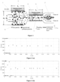
- embodiments of the present disclosure provide a device for separating sub-micron particles in the air, comprising a first separation channel 1, a second separation channel 2 and a collection device 3 which are connected in sequence.
- each of the first separation channel 1 and the second separation channel 2 is of a rectangle structure with two open ends, wherein the height H 1 of the first separation channel 1 is greater than the height H 2 of the second separation channel 2.
- the first separation channel 1 is in sealing connection with the second separation channel 2, and in one example, the two are in smooth transition connection, so that the particle flow formed by the sub-micron particles flowing into the first separation channel 1 can smoothly flow into the second separation channel 2.
- the spacing between the first separation channel 1 and the second separation channel 2 is not specially limited, as long as the smooth inflow of the particle flow can be achieved. In a specific example, the spacing between the two may be 0.05 m.
- the separation channels may be made of anti-vibration material, such as steel material or the like.
- the outer surface of the upper wall of each separation channel is provided with a vibration sound source, and when the air flow entrained with sub-micron particles moves in the positive direction of the x axis at a mean velocity U mean and is introduced into the first separation channel 1 from the left side, a standing wave field is generated in the y direction when the first vibration sound source 4 operates, as shown in Figure 1 .
- a coordinate system is constructed.
- the vibration sound source may be a high-frequency vibration generator.
- the outer surface of the upper wall of the first separation channel 1 is provided with a first vibration sound source 4, and the inner surfaces of the upper wall and the lower wall are provided with a first antimicrobial coating layer 6;
- the first vibration sound source 4 is used to generate a first standing wave field in the y direction, the first standing wave field is used to aggregate particles with a first diameter d p1 , and the first diameter d p1 is ranged from 350 nm to 1.2 ⁇ m, that is, the first separation channel 1 has a larger height and a lower standing wave frequency and is mainly responsible for aggregating sub-micron suspended particles with larger diameter, such as smaller bacterial particles.
- the outer surface of the upper wall of the second separation channel 2 is provided with a second vibration sound source 5, and the inner surfaces of the upper wall and the lower wall are provided with a second antimicrobial coating layer 7;
- the second vibration sound source 5 is used to generate a second standing wave field in the y direction, the second standing wave field is used to aggregate particles with a second diameter d p2 , and the second diameter d p2 is ranged from 80 nm to 500 nm, that is, the second separation channel 2 has a smaller height and a higher standing wave frequency and is responsible for aggregating particles with smaller diameter, such as most virus particles.
- the relationship between a standing wave frequency f a1 of the first standing wave field and the height H 1 is set such that particles flowing into the first separation channel are aggregated on the inner surface of the upper wall of the first separation channel, and the horizontal surface of the central axis in the y direction of the channel and the inner surface of the lower wall.
- the height of the first separation channel may be 2500 ⁇ m
- the standing wave frequency of the first standing wave field may be 136000 Hz
- the height of the second separation channel may be 1000 ⁇ m
- the standing wave frequency of the second standing wave field may be 340,000 Hz.
- the standing wave frequencies and channel heights shown in this example may be used to effectively aggregate sub-micron particles with diameter within the range of 80 nm-1.2 ⁇ m.
- the first antimicrobial coating layer 6 is used to adsorb particles aggregated on the inner surface of the upper wall and the inner surface of the lower wall of the first separation channel
- the second antimicrobial coating layer 7 is used to adsorb particles aggregated on the inner surface of the upper wall and the inner surface of the lower wall of the second separation channel, to attach and inactivate pathogenic micro-organism particles.
- the antimicrobial coating layers can be selected from the existing commercially available products, for example, Germagic long-acting disinfectant spray produced by Germagic Biological Technology (Shanghai) Limited.
- the collection device 3 is used to collect particles aggregated on the central surface.
- the collection device 3 may be an existing device, which is not particularly limited in the present disclosure, as long as the aggregated suspended particles can be collected and post-processed.
- the clean air processed by the antimicrobial coating layers and collection device may normally flow out along the channel from other positions in the y direction and be discharged to such as atmosphere or be used normally.
- the length of a separation channel when the standing wave amplitude of a standing wave field is fixed, the length of a separation channel is positively correlated with the mean flow velocity of the particles flowing in the separation channel; when the mean flow velocity of the particles flowing in the separation channel is fixed, the length of the separation channel is negatively correlated with the standing wave amplitude of the standing wave field; and when the length of the separation channel is fixed, the standing wave amplitude of the standing wave field is positively correlated with the mean flow velocity of particles flowing in the separation channel.
- the length L1 of the first separation channel 1 is positively correlated with the mean flow velocity U mean1 of the particles flowing in the first separation channel 1; when the mean flow velocity of the particles flowing in the first separation channel is maintained unchanged, the length of the first separation channel is negatively correlated with the standing wave amplitude p 1 of the first standing wave field; and when the length of the first separation channel is maintained unchanged, the standing wave amplitude p 1 of the first standing wave field is positively correlated with the mean flow velocity U mean1 of the particles flowing in the first separation channel.
- the length L2 of the second separation channel 2 is positively correlated with the mean flow velocity U mean2 of the particles flowing in the second separation channel; when the mean flow velocity of the particles flowing in the second separation channel is maintained unchanged, the length of the second separation channel is negatively correlated with the standing wave amplitude p 2 of the second standing wave field; and when the length of the second separation channel is maintained unchanged, the standing wave amplitude p 2 of the second standing wave field is positively correlated with the mean flow velocity U mean2 of the particles flowing in the second separation channel.
- the main parameters of the first separation channel 1 and the second separation channel 2 may be as shown in the following Table 1: Table 1: Main Parameters of Separation Channel First Separation Channel Height H 1 2500 ⁇ m Length L 1 0.15m - 0.25m Standing wave frequency f a1 136000Hz Mean flow velocity U mean 0.05m/s - 0.08m/s Standing wave amplitude p 1 1000Pa or more Diameter range of aggregated particles (smallest, best, largest) (350nm, 520nm, 1.2 ⁇ m) Second separation channel Height H 2 1000 ⁇ m Length L 2 0.25m - 0.35m Standing wave frequency f a2 340000Hz Mean flow velocity U mean 0.125m/s - 0.2m/s Standing wave amplitude p 2 1000Pa or more Diameter range of aggregated particles (smallest, best, largest) (80nm,
- Table 2 Simulation Parameters of Separation Channel: First Separation Channel Channel height H 1 2500 ⁇ m Channel length L 1 0.2m Standing wave frequency f a1 136000Hz Mean flow velocity U mean 0.08m/s Standing wave amplitude p 1 1000Pa Diameters of aggregated particles 350nm, 520nm, 750nm, 1 ⁇ m and 1.2 ⁇ m Second separation channel Channel height H 2 1000 ⁇ m Channel length L 2 0.3m Standing wave frequency f a2 340000Hz Mean flow velocity U mean 0.2m/s Standing wave amplitude p 2 1000Pa Diameters of aggregated 80nm,100nm,160nm,240nm,320nm, particles and 500nm
- simulating the aggregating process of particles with diameters of 350 nm, 520 nm, 750 nm, 1 ⁇ m and 1.2 ⁇ m is used to verify the aggregating effect thereof on particles with diameters greater than 500 nm and less than 1.2 ⁇ m; and (2) for the second separation channel, simulating the aggregating process of particles with diameters of 80 nm, 100 nm, 160 nm, 240 nm, 320 nm and 500 nm is used to verify the aggregating effect thereof on particles with diameter less than 500 nm.
- the simulation process focuses on the aggregating effect on particles (airborne viruses) with diameter within the range of 80 nm-300 nm.
- the value of the material density ⁇ mp of the particles during simulation is 1400kg/m3.
- the numerical simulation method defined by the following formulas (7)-(11) is used to verify the aggregating effects of the separation channels with the parameters shown in Table 2.
- the standing wave action time t measured during simulation and the coordinate y of the corresponding particles in the y direction, based on the above formulas (7)-(11), the spatial position and velocity of each particle may be obtained.
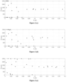
- the simulation results may be shown in Figures 2(a)-(e) and Figures 3(a)-(f) respectively.
- Figures 2 (a)-(e) respectively show the distribution and state of particles with five diameters of 350 nm, 520 nm, 750 nm, 1 ⁇ m and 1.2 ⁇ m in the first separation channel after 3 seconds of standing wave action.
- the standing wave has a slightly lower aggregating effect on same, however, when the particles move axially to the channel exit (0.15 m), the particles are basically aggregated in the theoretical positions, that is, on the inner surfaces of the two walls and centerline of the first separation channel.
- Figures 3(a)-(f) respectively show the distribution and state of particles with six diameters of 80nm, 100nm, 160nm, 240nm, 320nm and 500nmin in the second separation channel after 3 seconds of standing wave action.
- the standing wave has a slightly lower aggregating effect on same, however, when the particles move axially to the channel exit (0.25 m), the particles are basically aggregated in the theoretical positions, that is, on the inner surfaces of the two walls and centerline of the second separation channel.
- Figures 3(b)-(e) show the effect of the standing wave on the aggregating distribution of particles with diameter of 100 nm-320 nm.
- the device for separating sub-micron particles in the air can aggregate sub-micron suspended particles flowing into each channel of the device on the upper and lower wall surfaces and the centerline of the channel, and sterilize the aggregated particles, thereby effectively removing the sub-micron suspended particles in the air.
Landscapes
- Chemical & Material Sciences (AREA)
- Chemical Kinetics & Catalysis (AREA)
- Disinfection, Sterilisation Or Deodorisation Of Air (AREA)
- Physical Or Chemical Processes And Apparatus (AREA)
Claims (7)
- Dispositif de séparation de particules submicroniques dans l'air, comprenant : un premier canal de séparation (1), un second canal de séparation (2) et un dispositif de collecte (3) qui sont connectés en séquence,dans lequel chacun du premier canal de séparation (1) et du second canal de séparation (2) est de structure rectangulaire avec deux extrémités ouvertes, et la hauteur H1 du premier canal de séparation (1) est supérieure à la hauteur H2 du second canal de séparation (2) ;en prenant l'extrémité la plus à gauche de la surface interne de la paroi inférieure du premier canal de séparation (1) comme origine des coordonnées, la direction de la hauteur du premier canal de séparation (1) comme direction positive de l'axe y, et la direction de la longueur du premier canal de séparation (1) comme direction positive de l'axe x, un système de coordonnées est construit ;la surface externe de la paroi supérieure du premier canal de séparation (1) est pourvue d'une première source sonore de vibration (4), la première source sonore de vibration (4) est utilisée pour générer un premier champ d'onde stationnaire dans la direction y ;la surface externe de la paroi supérieure du second canal de séparation (2) est pourvue d'une seconde source sonore de vibration (5), la seconde source sonore de vibration (5) est utilisée pour générer un second champ d'onde stationnaire dans la direction y ;caractérisé en ce que :les surfaces internes de la paroi supérieure et de la paroi inférieure sont pourvues d'une première couche de revêtement antimicrobien (6) ; le premier champ d'onde stationnaire est utilisé pour agréger des particules ayant un premier diamètre d p1, et le premier diamètre d p1 est dans une plage entre 350 nm et 1,2 µm ;les surfaces internes de la paroi supérieure et de la paroi inférieure sont pourvues d'une seconde couche de revêtement antimicrobien (7) ; le second champ d'onde stationnaire est utilisé pour agréger des particules ayant un second diamètre d p2, et le second diamètre d p2 est dans une plage entre 80 nm et 500 nm ;la relation entre une fréquence d'onde stationnaire f a1 du premier champ d'onde stationnaire et la hauteur H1 est définie de telle sorte que les particules s'écoulant dans le premier canal de séparation (1) sont agrégées sur la surface interne de la paroi supérieure du premier canal de séparation (1), et la surface horizontale de l'axe central dans la direction y du canal et la surface interne de la paroi inférieure ; et la première couche de revêtement antimicrobien (6) est utilisée pour adsorber des particules agrégées sur la surface interne de la paroi supérieure et sur la surface interne de la paroi inférieure du premier canal de séparation (1), dans lequel la relation entre la fréquence des onde stationnaire f a1 du premier champ d'onde stationnaire et la hauteur H1 est fa1*H1= c 0, où c 0 représente la vitesse du son dans l'air ;la relation entre une fréquence d'onde stationnaire f a2 du second champ d'onde stationnaire et la hauteur H2 est définie de telle sorte que les particules s'écoulant dans le second canal de séparation (2) sont agrégées sur la surface interne de la paroi supérieure du second canal de séparation (2), et la surface horizontale de l'axe central dans la direction y du canal et la surface interne de la paroi inférieure ; et la seconde couche de revêtement antimicrobien (7) est utilisée pour adsorber des particules agrégées sur la surface interne de la paroi supérieure et sur la surface interne de la paroi inférieure du second canal de séparation (2), dans lequel la relation entre la fréquence d'onde stationnaire f a2 du second champ d'onde stationnaire et la hauteur H2 est : f a2*H2= c 0, où c 0 représente la vitesse du son dans l'air ;la relation entre la fréquence d'onde stationnaire du premier champ d'onde stationnaire et la fréquence d'onde stationnaire du second champ d'onde stationnaire et le diamètre des particules agrégées correspondantes est déterminée par les formules (1) à (4) suivantes :


 où τ 1 et τ 2 représentent le temps de relaxation de la force visqueuse de l'air dans le premier canal de séparation (1) et le second canal de séparation (2), respectivement, ρ mp représente la densité matérielle des particules, et µ g représente la viscosité dynamique de l'air ; etle dispositif de collecte (3) est utilisé pour collecter des particules agrégées sur la surface centrale.
 - Dispositif de séparation de particules submicroniques dans l'air selon la revendication 1, caractérisé en ce que : le premier canal de séparation (1) a une hauteur de 2500 µm, et le premier champ d'onde stationnaire a une fréquence d'onde stationnaire de 136 000 Hz. ; et le second canal de séparation (2) a une hauteur de 1000 µm, et le second champ d'onde stationnaire a une fréquence d'onde stationnaire de 340 000 Hz.
- Dispositif de séparation de particules submicroniques dans l'air selon la revendication 1, caractérisé en ce que : le premier canal de séparation (1) est en liaison de transition douce avec le second canal de séparation (2).
- Dispositif de séparation de particules submicroniques dans l'air selon la revendication 1, caractérisé en ce que : lorsque l'amplitude d'onde stationnaire du premier champ d'onde stationnaire est maintenue inchangée, la longueur du premier canal de séparation (1) est positivement corrélée avec la vitesse d'écoulement moyenne des particules s'écoulant dans le premier canal de séparation (1) ;lorsque la vitesse d'écoulement moyenne des particules s'écoulant dans le premier canal de séparation (1) est maintenue inchangée, la longueur du premier canal de séparation (1) est corrélée négativement avec l'amplitude d'onde stationnaire du premier champ d'onde stationnaire ; etlorsque la longueur du premier canal de séparation (1) est maintenue inchangée, l'amplitude d'onde stationnaire du premier champ d'onde stationnaire est positivement corrélée avec la vitesse d'écoulement moyenne des particules s'écoulant dans le premier canal de séparation (1).
- Dispositif de séparation de particules submicroniques dans l'air selon la revendication 4, caractérisé en ce que :la vitesse d'écoulement moyenne des particules s'écoulant dans le premier canal de séparation (1) est de 0,05 m/s à 0,08 m/s ;l'amplitude d'onde stationnaire du premier champ d'onde stationnaire est supérieure ou égale à 1000 Pa ; etle premier canal de séparation (1) a une longueur de 0,15 m à 0,25 m.
- Dispositif de séparation de particules submicroniques dans l'air selon la revendication 1, caractérisé en ce que : lorsque l'amplitude d'onde stationnaire du second champ d'onde stationnaire est maintenue inchangée, la longueur du second canal de séparation (2) est positivement corrélée avec la vitesse d'écoulement moyenne des particules s'écoulant dans le second canal de séparation (2) ;lorsque la vitesse d'écoulement moyenne des particules s'écoulant dans le second canal de séparation (2) est maintenue inchangée, la longueur du second canal de séparation (2) est corrélée négativement avec l'amplitude d'onde stationnaire du second champ d'onde stationnaire ; etlorsque la longueur du second canal de séparation (2) est maintenue inchangée, l'amplitude d'onde stationnaire du second champ d'onde stationnaire est positivement corrélée avec la vitesse d'écoulement moyenne des particules s'écoulant dans le second canal de séparation (2).
- Dispositif de séparation de particules submicroniques dans l'air selon la revendication 6, caractérisé en ce que :la vitesse d'écoulement moyenne de particules s'écoulant dans le second canal de séparation (2) est de 0,125 m/s à 0,2 m/s ;l'amplitude d'onde stationnaire du second champ d'onde stationnaire est supérieure ou égale à 1000 Pa ; et le second canal de séparation (2) a une longueur de 0,25 m à 0,35 m.
Applications Claiming Priority (1)
| Application Number | Priority Date | Filing Date | Title |
|---|---|---|---|
| PCT/CN2020/106702 WO2022027210A1 (fr) | 2020-08-04 | 2020-08-04 | Dispositif de séparation de particules submicrométriques dans l'air |
Publications (4)
| Publication Number | Publication Date |
|---|---|
| EP3978097A1 EP3978097A1 (fr) | 2022-04-06 |
| EP3978097A4 EP3978097A4 (fr) | 2022-07-06 |
| EP3978097C0 EP3978097C0 (fr) | 2024-09-25 |
| EP3978097B1 true EP3978097B1 (fr) | 2024-09-25 |
Family
ID=80119240
Family Applications (1)
| Application Number | Title | Priority Date | Filing Date |
|---|---|---|---|
| EP20913052.5A Active EP3978097B1 (fr) | 2020-08-04 | 2020-08-04 | Dispositif de séparation de particules submicrométriques dans l'air |
Country Status (3)
| Country | Link |
|---|---|
| US (1) | US11925893B2 (fr) |
| EP (1) | EP3978097B1 (fr) |
| WO (1) | WO2022027210A1 (fr) |
Families Citing this family (1)
| Publication number | Priority date | Publication date | Assignee | Title |
|---|---|---|---|---|
| CN119548933B (zh) * | 2024-11-27 | 2025-12-09 | 国能神华九江发电有限责任公司 | 一种智能高强声波团聚声源系统 |
Family Cites Families (19)
| Publication number | Priority date | Publication date | Assignee | Title |
|---|---|---|---|---|
| US4339247A (en) * | 1981-04-27 | 1982-07-13 | Battelle Development Corporation | Acoustic degasification of pressurized liquids |
| CN1091626C (zh) | 1994-04-28 | 2002-10-02 | 王晓庆 | 一种利用超声分离悬浮颗粒的仪器 |
| JP3487699B2 (ja) * | 1995-11-08 | 2004-01-19 | 株式会社日立製作所 | 超音波処理方法および装置 |
| GB9708984D0 (en) * | 1997-05-03 | 1997-06-25 | Univ Cardiff | Particle manipulation |
| US7340957B2 (en) * | 2004-07-29 | 2008-03-11 | Los Alamos National Security, Llc | Ultrasonic analyte concentration and application in flow cytometry |
| SE528313C2 (sv) * | 2004-09-24 | 2006-10-17 | Spectronic Ab | Metod och apparat för separering av partiklar med hjälp av ultraljudvågor |
| ATE538377T1 (de) * | 2007-04-02 | 2012-01-15 | Acoustic Cytometry Systems Inc | Verfahren zur verbesserten analyse von in einem akustischen feld fokussierten zellen und partikeln |
| ES2326109B1 (es) | 2007-12-05 | 2010-06-25 | Consejo Superior De Investigaciones Cientificas | Microdispositivo de separacion y extraccion selectiva y no invasiva de particulas en suspensiones polidispersas, procedimiento de fabricacion y sus aplicaciones. |
| US8714014B2 (en) * | 2008-01-16 | 2014-05-06 | Life Technologies Corporation | System and method for acoustic focusing hardware and implementations |
| US8387803B2 (en) * | 2008-08-26 | 2013-03-05 | Ge Healthcare Bio-Sciences Ab | Particle sorting |
| WO2012135663A2 (fr) * | 2011-03-31 | 2012-10-04 | University Of South Florida | Dispositif microfluidique à deux étages pour manipulation acoustique de particules et procédés de séparation |
| CN102527488A (zh) * | 2011-12-27 | 2012-07-04 | 中国矿业大学 | 一种微纳米颗粒超声分离装置 |
| US9272234B2 (en) * | 2012-03-15 | 2016-03-01 | Flodesign Sonics, Inc. | Separation of multi-component fluid through ultrasonic acoustophoresis |
| WO2014210046A1 (fr) * | 2013-06-24 | 2014-12-31 | Flodesign Sonics, Inc. | Séparateur sonique par la dynamique des fluides |
| CA2948355A1 (fr) * | 2014-05-08 | 2015-11-12 | Bart Lipkens | Dispositif d'acoustophorese comprenant un ensemble de transducteurs piezoelectriques |
| US10161926B2 (en) * | 2015-06-11 | 2018-12-25 | Flodesign Sonics, Inc. | Acoustic methods for separation of cells and pathogens |
| WO2017153038A2 (fr) * | 2016-03-06 | 2017-09-14 | WindplusSonne GmbH | Procédé et dispositif de séparation et/ou de nettoyage d'aérosols et de particules et de fibres solides de gaz, ainsi que de particules et de fibres solides de fluides par acoustophorèse |
| CN106853381B (zh) | 2016-12-16 | 2024-02-02 | 苏州国科昂卓医疗科技有限公司 | 一种粒子分离装置、系统及粒子分离方法 |
| EP4145101B1 (fr) * | 2021-07-13 | 2024-07-03 | Beihang University | Plate-forme de test pour performance globale de revêtement acoustique |
-
2020
- 2020-08-04 EP EP20913052.5A patent/EP3978097B1/fr active Active
- 2020-08-04 US US17/424,471 patent/US11925893B2/en active Active
- 2020-08-04 WO PCT/CN2020/106702 patent/WO2022027210A1/fr not_active Ceased
Also Published As
| Publication number | Publication date |
|---|---|
| US11925893B2 (en) | 2024-03-12 |
| EP3978097C0 (fr) | 2024-09-25 |
| EP3978097A1 (fr) | 2022-04-06 |
| EP3978097A4 (fr) | 2022-07-06 |
| US20220305426A1 (en) | 2022-09-29 |
| WO2022027210A1 (fr) | 2022-02-10 |
Similar Documents
| Publication | Publication Date | Title |
|---|---|---|
| CN103736356B (zh) | 一种声波凝聚-常规除尘复合的脱除细颗粒物的装置 | |
| WO2017153038A3 (fr) | Procédé et dispositif de séparation et/ou de nettoyage d'aérosols et de particules et de fibres solides de gaz, ainsi que de particules et de fibres solides de fluides par acoustophorèse | |
| EP3978097B1 (fr) | Dispositif de séparation de particules submicrométriques dans l'air | |
| CN104226051B (zh) | 基于电-高频振动转化的超声波强化雾化喷淋除霾降尘装置及方法 | |
| Sun et al. | Coupling effect of gas jet and acoustic wave on inhalable particle agglomeration | |
| US5904752A (en) | Method for collecting airborne particles and microorganisms by their injection into a swirling air flow | |
| Khmelev et al. | Efficiency increase of centrifugal separation of gas-dispersed flow by the application of ultrasonic vibrations | |
| CN100427772C (zh) | 在流体流中的改善的颗粒的相互作用 | |
| CN116712817A (zh) | 筛帘阵列和沉降装置以及废气处理方法 | |
| Khmelev et al. | Revealing of optimum modes of ultrasonic coagulation of submicron particles and determining of the shape of the aggregates by mathematical modeling | |
| Khmelev et al. | Development of the construction of the apparatus for centrifugal acoustic collection of nanoscale aerosols | |
| EP4487099B1 (fr) | Dispositif pour l'échantillonnage de partucles aéroportées | |
| CN109420385B (zh) | 一种涡式空气净化器 | |
| Khmelyov et al. | Numerical model of ultrasonic agglomeration of submicron particles in resonant gas gaps | |
| US20180003110A1 (en) | Acoustically-Enhanced Separators for Aircraft Engines | |
| US8236092B1 (en) | Pressure gradient gas scrubber apparatus and method | |
| CA2568932A1 (fr) | Separateur cyclonique a cassure de vortex secondaire | |
| CN211318488U (zh) | 一种天然气流场测量用示踪粒子的发生和分离装置 | |
| Chen et al. | The virtual cyclone as a personal respirable sampler | |
| Bae et al. | Non-powered dust removal device attached underneath a train cabin in a subway tunnel | |
| George et al. | On the fragility of acoustically agglomerated submicron fly ash particles | |
| CN104436949A (zh) | 一种用于金属粉尘蒸汽收集与过滤装置 | |
| Pérez-Díaz et al. | Apparatus and methods for sampling air-borne particles | |
| Khmelev et al. | Raising the Efficiency of Coagulation of Dispersed Particles by the Action of Ultrasonic Vibrations on Gas-Dispersed Flows in Inertial Dust Collectors | |
| Pérez-Díaz et al. | Apparatus for sampling air-borne particles |
Legal Events
| Date | Code | Title | Description |
|---|---|---|---|
| STAA | Information on the status of an ep patent application or granted ep patent |
Free format text: STATUS: UNKNOWN |
|
| STAA | Information on the status of an ep patent application or granted ep patent |
Free format text: STATUS: THE INTERNATIONAL PUBLICATION HAS BEEN MADE |
|
| PUAI | Public reference made under article 153(3) epc to a published international application that has entered the european phase |
Free format text: ORIGINAL CODE: 0009012 |
|
| STAA | Information on the status of an ep patent application or granted ep patent |
Free format text: STATUS: REQUEST FOR EXAMINATION WAS MADE |
|
| 17P | Request for examination filed |
Effective date: 20210726 |
|
| AK | Designated contracting states |
Kind code of ref document: A1 Designated state(s): AL AT BE BG CH CY CZ DE DK EE ES FI FR GB GR HR HU IE IS IT LI LT LU LV MC MK MT NL NO PL PT RO RS SE SI SK SM TR |
|
| A4 | Supplementary search report drawn up and despatched |
Effective date: 20220608 |
|
| RIC1 | Information provided on ipc code assigned before grant |
Ipc: B01D 49/00 20060101AFI20220601BHEP |
|
| RIN1 | Information on inventor provided before grant (corrected) |
Inventor name: LIU, JIZHOU Inventor name: LI, XIAODONG |
|
| DAV | Request for validation of the european patent (deleted) | ||
| DAX | Request for extension of the european patent (deleted) | ||
| GRAP | Despatch of communication of intention to grant a patent |
Free format text: ORIGINAL CODE: EPIDOSNIGR1 |
|
| STAA | Information on the status of an ep patent application or granted ep patent |
Free format text: STATUS: GRANT OF PATENT IS INTENDED |
|
| RAP3 | Party data changed (applicant data changed or rights of an application transferred) |
Owner name: BEIHANG UNIVERSITY |
|
| INTG | Intention to grant announced |
Effective date: 20240624 |
|
| RAP3 | Party data changed (applicant data changed or rights of an application transferred) |
Owner name: BEIHANG UNIVERSITY |
|
| GRAS | Grant fee paid |
Free format text: ORIGINAL CODE: EPIDOSNIGR3 |
|
| GRAA | (expected) grant |
Free format text: ORIGINAL CODE: 0009210 |
|
| STAA | Information on the status of an ep patent application or granted ep patent |
Free format text: STATUS: THE PATENT HAS BEEN GRANTED |
|
| AK | Designated contracting states |
Kind code of ref document: B1 Designated state(s): AL AT BE BG CH CY CZ DE DK EE ES FI FR GB GR HR HU IE IS IT LI LT LU LV MC MK MT NL NO PL PT RO RS SE SI SK SM TR |
|
| REG | Reference to a national code |
Ref country code: GB Ref legal event code: FG4D |
|
| REG | Reference to a national code |
Ref country code: CH Ref legal event code: EP |
|
| REG | Reference to a national code |
Ref country code: DE Ref legal event code: R096 Ref document number: 602020038516 Country of ref document: DE |
|
| REG | Reference to a national code |
Ref country code: IE Ref legal event code: FG4D |
|
| U01 | Request for unitary effect filed |
Effective date: 20241022 |
|
| U07 | Unitary effect registered |
Designated state(s): AT BE BG DE DK EE FI FR IT LT LU LV MT NL PT RO SE SI Effective date: 20241029 |
|
| PG25 | Lapsed in a contracting state [announced via postgrant information from national office to epo] |
Ref country code: NO Free format text: LAPSE BECAUSE OF FAILURE TO SUBMIT A TRANSLATION OF THE DESCRIPTION OR TO PAY THE FEE WITHIN THE PRESCRIBED TIME-LIMIT Effective date: 20241225 |
|
| PG25 | Lapsed in a contracting state [announced via postgrant information from national office to epo] |
Ref country code: GR Free format text: LAPSE BECAUSE OF FAILURE TO SUBMIT A TRANSLATION OF THE DESCRIPTION OR TO PAY THE FEE WITHIN THE PRESCRIBED TIME-LIMIT Effective date: 20241226 |
|
| PG25 | Lapsed in a contracting state [announced via postgrant information from national office to epo] |
Ref country code: RS Free format text: LAPSE BECAUSE OF FAILURE TO SUBMIT A TRANSLATION OF THE DESCRIPTION OR TO PAY THE FEE WITHIN THE PRESCRIBED TIME-LIMIT Effective date: 20241225 |
|
| PG25 | Lapsed in a contracting state [announced via postgrant information from national office to epo] |
Ref country code: RS Free format text: LAPSE BECAUSE OF FAILURE TO SUBMIT A TRANSLATION OF THE DESCRIPTION OR TO PAY THE FEE WITHIN THE PRESCRIBED TIME-LIMIT Effective date: 20241225 Ref country code: NO Free format text: LAPSE BECAUSE OF FAILURE TO SUBMIT A TRANSLATION OF THE DESCRIPTION OR TO PAY THE FEE WITHIN THE PRESCRIBED TIME-LIMIT Effective date: 20241225 Ref country code: GR Free format text: LAPSE BECAUSE OF FAILURE TO SUBMIT A TRANSLATION OF THE DESCRIPTION OR TO PAY THE FEE WITHIN THE PRESCRIBED TIME-LIMIT Effective date: 20241226 |
|
| PG25 | Lapsed in a contracting state [announced via postgrant information from national office to epo] |
Ref country code: IS Free format text: LAPSE BECAUSE OF FAILURE TO SUBMIT A TRANSLATION OF THE DESCRIPTION OR TO PAY THE FEE WITHIN THE PRESCRIBED TIME-LIMIT Effective date: 20250125 |
|
| PG25 | Lapsed in a contracting state [announced via postgrant information from national office to epo] |
Ref country code: SM Free format text: LAPSE BECAUSE OF FAILURE TO SUBMIT A TRANSLATION OF THE DESCRIPTION OR TO PAY THE FEE WITHIN THE PRESCRIBED TIME-LIMIT Effective date: 20240925 |
|
| PG25 | Lapsed in a contracting state [announced via postgrant information from national office to epo] |
Ref country code: ES Free format text: LAPSE BECAUSE OF FAILURE TO SUBMIT A TRANSLATION OF THE DESCRIPTION OR TO PAY THE FEE WITHIN THE PRESCRIBED TIME-LIMIT Effective date: 20240925 |
|
| PG25 | Lapsed in a contracting state [announced via postgrant information from national office to epo] |
Ref country code: CZ Free format text: LAPSE BECAUSE OF FAILURE TO SUBMIT A TRANSLATION OF THE DESCRIPTION OR TO PAY THE FEE WITHIN THE PRESCRIBED TIME-LIMIT Effective date: 20240925 Ref country code: PL Free format text: LAPSE BECAUSE OF FAILURE TO SUBMIT A TRANSLATION OF THE DESCRIPTION OR TO PAY THE FEE WITHIN THE PRESCRIBED TIME-LIMIT Effective date: 20240925 |
|
| PG25 | Lapsed in a contracting state [announced via postgrant information from national office to epo] |
Ref country code: SK Free format text: LAPSE BECAUSE OF FAILURE TO SUBMIT A TRANSLATION OF THE DESCRIPTION OR TO PAY THE FEE WITHIN THE PRESCRIBED TIME-LIMIT Effective date: 20240925 |
|
| PLBE | No opposition filed within time limit |
Free format text: ORIGINAL CODE: 0009261 |
|
| STAA | Information on the status of an ep patent application or granted ep patent |
Free format text: STATUS: NO OPPOSITION FILED WITHIN TIME LIMIT |
|
| U20 | Renewal fee for the european patent with unitary effect paid |
Year of fee payment: 6 Effective date: 20250723 |
|
| 26N | No opposition filed |
Effective date: 20250626 |
|
| U1N | Appointed representative for the unitary patent procedure changed after the registration of the unitary effect |
Representative=s name: SANTARELLI; FR |
|
| PG25 | Lapsed in a contracting state [announced via postgrant information from national office to epo] |
Ref country code: HR Free format text: LAPSE BECAUSE OF FAILURE TO SUBMIT A TRANSLATION OF THE DESCRIPTION OR TO PAY THE FEE WITHIN THE PRESCRIBED TIME-LIMIT Effective date: 20240925 |
|
| REG | Reference to a national code |
Ref country code: CH Ref legal event code: H13 Free format text: ST27 STATUS EVENT CODE: U-0-0-H10-H13 (AS PROVIDED BY THE NATIONAL OFFICE) Effective date: 20260324 |
|
| PG25 | Lapsed in a contracting state [announced via postgrant information from national office to epo] |
Ref country code: MC Free format text: LAPSE BECAUSE OF FAILURE TO SUBMIT A TRANSLATION OF THE DESCRIPTION OR TO PAY THE FEE WITHIN THE PRESCRIBED TIME-LIMIT Effective date: 20240925 |