EP3978061A1 - Balloon catheter - Google Patents
Balloon catheter Download PDFInfo
- Publication number
- EP3978061A1 EP3978061A1 EP19930712.5A EP19930712A EP3978061A1 EP 3978061 A1 EP3978061 A1 EP 3978061A1 EP 19930712 A EP19930712 A EP 19930712A EP 3978061 A1 EP3978061 A1 EP 3978061A1
- Authority
- EP
- European Patent Office
- Prior art keywords
- hollow shaft
- balloon
- distal end
- joint part
- proximal end
- Prior art date
- Legal status (The legal status is an assumption and is not a legal conclusion. Google has not performed a legal analysis and makes no representation as to the accuracy of the status listed.)
- Withdrawn
Links
- 230000008602 contraction Effects 0.000 claims description 5
- 208000007536 Thrombosis Diseases 0.000 abstract description 26
- 239000000463 material Substances 0.000 description 21
- 210000004204 blood vessel Anatomy 0.000 description 15
- 238000000034 method Methods 0.000 description 11
- 235000019589 hardness Nutrition 0.000 description 9
- 239000007788 liquid Substances 0.000 description 9
- 239000011347 resin Substances 0.000 description 4
- 229920005989 resin Polymers 0.000 description 4
- 210000005259 peripheral blood Anatomy 0.000 description 3
- 239000011886 peripheral blood Substances 0.000 description 3
- 238000003466 welding Methods 0.000 description 3
- 239000004952 Polyamide Substances 0.000 description 2
- 229920001971 elastomer Polymers 0.000 description 2
- 239000000806 elastomer Substances 0.000 description 2
- 230000000149 penetrating effect Effects 0.000 description 2
- 229920002647 polyamide Polymers 0.000 description 2
- 229920000728 polyester Polymers 0.000 description 2
- 229920001296 polysiloxane Polymers 0.000 description 2
- 229920002635 polyurethane Polymers 0.000 description 2
- 239000004814 polyurethane Substances 0.000 description 2
- 229910045601 alloy Inorganic materials 0.000 description 1
- 239000000956 alloy Substances 0.000 description 1
- 230000000903 blocking effect Effects 0.000 description 1
- 230000001684 chronic effect Effects 0.000 description 1
- 230000003247 decreasing effect Effects 0.000 description 1
- 230000000694 effects Effects 0.000 description 1
- 239000007924 injection Substances 0.000 description 1
- 238000002347 injection Methods 0.000 description 1
- 238000003780 insertion Methods 0.000 description 1
- 230000037431 insertion Effects 0.000 description 1
- 239000007769 metal material Substances 0.000 description 1
- 238000012986 modification Methods 0.000 description 1
- 230000004048 modification Effects 0.000 description 1
- 229910001000 nickel titanium Inorganic materials 0.000 description 1
- 230000002093 peripheral effect Effects 0.000 description 1
- 239000002504 physiological saline solution Substances 0.000 description 1
- 229920000098 polyolefin Polymers 0.000 description 1
- 239000007779 soft material Substances 0.000 description 1
- 239000000243 solution Substances 0.000 description 1
- 239000010935 stainless steel Substances 0.000 description 1
- 229910001220 stainless steel Inorganic materials 0.000 description 1
- 230000000638 stimulation Effects 0.000 description 1
Images




Classifications
-
- A—HUMAN NECESSITIES
- A61—MEDICAL OR VETERINARY SCIENCE; HYGIENE
- A61M—DEVICES FOR INTRODUCING MEDIA INTO, OR ONTO, THE BODY; DEVICES FOR TRANSDUCING BODY MEDIA OR FOR TAKING MEDIA FROM THE BODY; DEVICES FOR PRODUCING OR ENDING SLEEP OR STUPOR
- A61M25/00—Catheters; Hollow probes
- A61M25/10—Balloon catheters
- A61M25/1002—Balloon catheters characterised by balloon shape
-
- A—HUMAN NECESSITIES
- A61—MEDICAL OR VETERINARY SCIENCE; HYGIENE
- A61B—DIAGNOSIS; SURGERY; IDENTIFICATION
- A61B17/00—Surgical instruments, devices or methods
- A61B17/32—Surgical cutting instruments
- A61B17/3205—Excision instruments
- A61B17/3207—Atherectomy devices working by cutting or abrading; Similar devices specially adapted for non-vascular obstructions
- A61B2017/320716—Atherectomy devices working by cutting or abrading; Similar devices specially adapted for non-vascular obstructions comprising means for preventing embolism by dislodged material
-
- A—HUMAN NECESSITIES
- A61—MEDICAL OR VETERINARY SCIENCE; HYGIENE
- A61M—DEVICES FOR INTRODUCING MEDIA INTO, OR ONTO, THE BODY; DEVICES FOR TRANSDUCING BODY MEDIA OR FOR TAKING MEDIA FROM THE BODY; DEVICES FOR PRODUCING OR ENDING SLEEP OR STUPOR
- A61M25/00—Catheters; Hollow probes
- A61M25/0067—Catheters; Hollow probes characterised by the distal end, e.g. tips
- A61M25/008—Strength or flexibility characteristics of the catheter tip
- A61M2025/0081—Soft tip
-
- A—HUMAN NECESSITIES
- A61—MEDICAL OR VETERINARY SCIENCE; HYGIENE
- A61M—DEVICES FOR INTRODUCING MEDIA INTO, OR ONTO, THE BODY; DEVICES FOR TRANSDUCING BODY MEDIA OR FOR TAKING MEDIA FROM THE BODY; DEVICES FOR PRODUCING OR ENDING SLEEP OR STUPOR
- A61M25/00—Catheters; Hollow probes
- A61M25/10—Balloon catheters
- A61M25/1002—Balloon catheters characterised by balloon shape
- A61M2025/1004—Balloons with folds, e.g. folded or multifolded
-
- A—HUMAN NECESSITIES
- A61—MEDICAL OR VETERINARY SCIENCE; HYGIENE
- A61M—DEVICES FOR INTRODUCING MEDIA INTO, OR ONTO, THE BODY; DEVICES FOR TRANSDUCING BODY MEDIA OR FOR TAKING MEDIA FROM THE BODY; DEVICES FOR PRODUCING OR ENDING SLEEP OR STUPOR
- A61M25/00—Catheters; Hollow probes
- A61M25/10—Balloon catheters
- A61M2025/1043—Balloon catheters with special features or adapted for special applications
- A61M2025/1065—Balloon catheters with special features or adapted for special applications having a balloon which is inversely attached to the shaft at the distal or proximal end
-
- A—HUMAN NECESSITIES
- A61—MEDICAL OR VETERINARY SCIENCE; HYGIENE
- A61M—DEVICES FOR INTRODUCING MEDIA INTO, OR ONTO, THE BODY; DEVICES FOR TRANSDUCING BODY MEDIA OR FOR TAKING MEDIA FROM THE BODY; DEVICES FOR PRODUCING OR ENDING SLEEP OR STUPOR
- A61M25/00—Catheters; Hollow probes
- A61M25/10—Balloon catheters
- A61M2025/1043—Balloon catheters with special features or adapted for special applications
- A61M2025/1068—Balloon catheters with special features or adapted for special applications having means for varying the length or diameter of the deployed balloon, this variations could be caused by excess pressure
-
- A—HUMAN NECESSITIES
- A61—MEDICAL OR VETERINARY SCIENCE; HYGIENE
- A61M—DEVICES FOR INTRODUCING MEDIA INTO, OR ONTO, THE BODY; DEVICES FOR TRANSDUCING BODY MEDIA OR FOR TAKING MEDIA FROM THE BODY; DEVICES FOR PRODUCING OR ENDING SLEEP OR STUPOR
- A61M25/00—Catheters; Hollow probes
- A61M25/10—Balloon catheters
- A61M2025/1043—Balloon catheters with special features or adapted for special applications
- A61M2025/1088—Balloon catheters with special features or adapted for special applications having special surface characteristics depending on material properties or added substances, e.g. for reducing friction
-
- A—HUMAN NECESSITIES
- A61—MEDICAL OR VETERINARY SCIENCE; HYGIENE
- A61M—DEVICES FOR INTRODUCING MEDIA INTO, OR ONTO, THE BODY; DEVICES FOR TRANSDUCING BODY MEDIA OR FOR TAKING MEDIA FROM THE BODY; DEVICES FOR PRODUCING OR ENDING SLEEP OR STUPOR
- A61M25/00—Catheters; Hollow probes
- A61M25/10—Balloon catheters
- A61M2025/1043—Balloon catheters with special features or adapted for special applications
- A61M2025/109—Balloon catheters with special features or adapted for special applications having balloons for removing solid matters, e.g. by grasping or scraping plaque, thrombus or other matters that obstruct the flow
-
- A—HUMAN NECESSITIES
- A61—MEDICAL OR VETERINARY SCIENCE; HYGIENE
- A61M—DEVICES FOR INTRODUCING MEDIA INTO, OR ONTO, THE BODY; DEVICES FOR TRANSDUCING BODY MEDIA OR FOR TAKING MEDIA FROM THE BODY; DEVICES FOR PRODUCING OR ENDING SLEEP OR STUPOR
- A61M25/00—Catheters; Hollow probes
- A61M25/10—Balloon catheters
- A61M25/1027—Making of balloon catheters
- A61M25/1034—Joining of shaft and balloon
Definitions
- the present invention relates to a balloon catheter.
- a technique in which the debris is intercepted by placing a balloon of a balloon catheter downstream of a treatment part and temporarily blocking the bloodstream.
- a flexible distal end portion for leading the balloon is disposed on a hollow shaft, in some cases.
- an expandable section of the balloon guided by the distal end portion can be smoothly pushed forward to the treatment part in the blood vessel, and a damage to the blood vessel can be reduced.
- Patent Literature 1 JP2007-252895
- the flexible distal end portion is placed on a distal end side with respect to the joint part between the balloon and the hollow shaft, disposed on the distal end of the balloon, and therefore debris such as thrombus adhering to the distal end portion and/or the joint part during treatment may peel off after contraction of the balloon and flow into the peripheral blood vessel.
- the present invention has been made on the basis of the above circumstances, and an object of the disclosed embodiments is to provide a balloon catheter capable of preventing debris such as thrombus from adhering to a distal end portion of a hollow shaft and a joint part between a balloon and the hollow shaft.
- This disclosure includes some aspects:
- distal end side means a direction along a longitudinal axis direction of the hollow shaft and toward a treatment part.
- proximal end side means a direction along the longitudinal axis direction of the hollow shaft and opposite to the distal end side.
- distal end refers to a distal end portion of any member or part
- proximal end refers to a proximal end portion of any member or part.
- distal end portion refers to a part that includes a distal end of any member or part and extends from the distal end to a middle of a way toward the proximal end side.
- proximal end portion refers to a part that includes a proximal end of any member or part and extends from the proximal end to a middle of a way toward the distal end side.
- the present invention can provide a balloon catheter capable of preventing debris such as thrombus from adhering to a distal end portion of a hollow shaft and a joint part between a balloon and the hollow shaft.
- the balloon catheter includes a hollow shaft and an expandable and contractable balloon placed so as to cover at least a part of an outer periphery of the hollow shaft, in which the balloon has a first joint part joined to the outer periphery of the hollow shaft, a second joint part located on a proximal end side with respect to the first joint part and joined to an outer periphery of the hollow shaft, and an expandable section continuous with the first joint part and the second joint part, the first joint part is wholly located inside the expandable section, and a distal end of the first joint part is spaced apart from a distal end of the hollow shaft toward a proximal end side.
- FIG. 1 is a schematic sectional view of a whole of the first embodiment.
- a balloon catheter 1 is roughly composed of a hollow shaft 11, a balloon 21, and a connector 31.
- the hollow shaft 11 is a shaft having a hollow shape.
- the hollow shaft 11 has a through-hole (hereinafter also referred to as a "main lumen 11b") having an opening 11c on the distal end and penetrating the hollow shaft 11 from the distal end to the proximal end.
- a medical device such as a guide wire and a device for crashing thrombus, or the like is inserted into the main lumen 11b.
- the hollow shaft 11 has a through-hole (hereinafter also referred to as “expansion lumen 11d”) having an opening 11e that adjoins the inside of the balloon 21 described later and penetrating from the opening 11e to the proximal end of the hollow shaft 11.
- a liquid for expanding and contracting the balloon 21 hereinafter also referred to as “expansion liquid" passes through the expansion lumen 11d.
- the hollow shaft 11 can be composed of e.g. a distal end-side hollow shaft 11A located on the distal end side, and a proximal end-side hollow shaft 11B joined to the proximal end of the distal end-side hollow shaft 11A and extending toward the proximal end side.
- the main lumen 11b and the expansion lumen 11d are provided across the distal end-side hollow shaft 11A and the proximal end-side hollow shaft 11B.
- materials constituting the distal end-side hollow shaft 11A and the proximal end-side hollow shaft 11B have antithrombogenicity, flexibility and biocompatibility, because the shafts are inserted into a body cavity.
- a resin material such as a polyamide, a polyamide elastomer, a polyolefin, a polyester, a polyester elastomer, a polyurethane, a silicone, and a fluororesin, or the like.
- proximal end-side hollow shaft 11B it is possible to adopt e.g.
- a resin material having a higher rigidity than of the distal end-side hollow shaft 11A a metal material such as a stainless steel (SUS304, and the like) and a superelastic alloy (nickel-titanium alloy, and the like), or the like.
- the balloon 21 is an expandable and contractable member placed so as to cover at least a part of the outer periphery of the hollow shaft 11.
- the balloon 21 has a first joint part 21a, a second joint part 21b, and an expandable section 21c.
- the expandable section 21c can be expanded by injecting the expansion liquid into the inside of the balloon 21 (a space surrounded by the first joint part 21a, the second joint part 21b, the expandable section 21c, and the outer periphery of the hollow shaft 11) through the opening 11e, so that e.g. the outer peripheral face of the balloon 21 can press an inner wall of a blood vessel or expand a constricted part.
- the first joint part 21a is a part where the balloon 21 is joined to the outer periphery of the hollow shaft 11.
- the first joint part 21a is wholly located inside the expandable section 21c.
- the distal end of the first joint part 21a is spaced apart from the distal end of the hollow shaft 11 toward the proximal end side.
- a distal end portion of a sheet-like member constituting the balloon 21 is turned back toward the proximal end side and this turned portion and the outer periphery of the hollow shaft 11 are joined to each other by heat welding or the like, so that the first joint part 21a can be formed.
- the second joint part 21b is located on the proximal end side with respect to the first joint part 21a, where the balloon 21 is joined to the outer periphery of the hollow shaft 11. Specifically, for example, after turning back the sheet-like member constituting the balloon 21 toward the proximal end side and joining the sheet-like member at the first joint part 21a, the proximal end portion of the turned portion and the outer periphery of the hollow shaft 11 are joined to each other by heat welding or the like, and thus the second joint part 21b can be formed.
- the expandable section 21c is continuous with the first joint part 21a and the second joint part 21b.
- the expandable section 21c is configured so as to expand radially outward and toward the distal and proximal end sides in the longitudinal axis direction by injecting the expansion liquid into the balloon 21.
- the balloon 21 can be formed of e.g. a stretchable sheet-like member.
- a material constituting the balloon 21 has stretchability, ease of joining, antithrombogenicity, and biocompatibility. Examples of such a material include resin materials such as silicone and polyurethane, and the like.
- the connector 31 is an operating part where a medical device is inserted or retracted through the main lumen 11b of the hollow shaft 11 and/or where the expansion liquid is injected or removed through the expansion lumen 11d.
- the connector 31 is connected to the proximal end of the proximal end-side hollow shaft 11B, and includes a passage hole 31b communicating with the main lumen 11b and having an opening 31c on the proximal end side, and a passage hole 31d communicating with the expansion lumen 11d and having an opening 31e on the proximal end side.
- a whole length of the hollow shaft 11 is 900 mm to 2000 mm
- a distance between the distal end of the hollow shaft 11 and the distal end of the first joint part 21a is 1 mm to 10 mm
- a distance between the distal end of the first joint part 21a and the proximal end of the second joint part 21b is 5 mm to 50mm.
- an outer diameter of the hollow shaft 11 is 1 mm to 5 mm
- an outer diameter of the balloon 21 is 1 mm to 6 mm in the decreased-diameter state and 2 mm to 20 mm in the increased-diameter state.
- an inner diameter of the main lumen 11b is 0.5 mm to 3 mm
- an inner diameter of the expansion lumen 11d is 0.1 mm to 1mm.
- the usage manner of the balloon catheter 1 will be explained with reference to FIG. 1 and FIG. 2 .
- a procedure in which the balloon catheter 1 is a guiding catheter equipped with a balloon, and thrombus caused in a blood vessel is removed and collected, will be exemplified.
- a guide wire (not illustrated), an angiographic catheter (not illustrated), and the balloon catheter 1 with the balloon 21 in a decreased-diameter state are inserted into a blood vessel.
- the balloon catheter is pushed forward till just before a part where the thrombus is formed (hereinafter, also referred to as "treatment part") while the guide wire and the angiographic catheter are advanced ahead of the balloon catheter.
- the guide wire and the angiographic catheter are removed out of the body.
- a thrombus collecting device is inserted from the opening 31c of the balloon catheter 1, and a distal end side of the thrombus collecting device is advanced from the opening 11c through the main lumen 11b. Subsequently, the distal end of the thrombus collecting device is pushed forward to the treatment part. Then, an expansion liquid such as physiological saline is injected into the balloon 21 from the opening 31e through the passage hole 31d and the expansion lumen 11d to expand the balloon 21.
- an expansion liquid such as physiological saline is injected into the balloon 21 from the opening 31e through the passage hole 31d and the expansion lumen 11d to expand the balloon 21.
- the outer periphery of the balloon 21 abuts on an inner wall of the blood vessel to intercept the bloodstream, and the balloon 21 proceeds toward the distal end side, so that the outer periphery of the distal end portion 11a of the hollow shaft 11 (outer periphery on the distal end side with respect to the first joint part 21a in the hollow shaft 11) is covered with the expandable section 21c.
- the thrombus is crushed, and meanwhile the debris of the thrombus is captured and collected in the thrombus collecting device. Then, after finishing the collection of the thrombus by the thrombus collecting device, the thrombus collecting device and the balloon catheter 1 (in a state that the diameter of the balloon is decreased) are removed out of the body in this order, so that the use of the balloon catheter 1 is completed.
- the balloon catheter 1 since the balloon catheter 1 has a configuration in which the whole first joint part 21a is located inside the expandable section 21c, the distal end portion 11a on the distal end side of the hollow shaft 11 can be placed so as to be exposed.
- the distal end portion 11a of the balloon catheter 1 is made of a soft material that does not damage the blood vessel inner wall even when coming into contact with the blood vessel inner wall.
- the distal end portion 11a of the balloon catheter 1 can be exposed. As a result, when inserting the balloon catheter 1 into the blood vessel, damage to the blood vessel inner wall can be suppressed.
- the distal end of the expandable section 21c can proceed to a more distal end side to cover the distal end portion 11a of the hollow shaft 11 and the first joint part 21a, so that debris such as thrombus can be prevented from adhering to the distal end portion 11a and the first joint part 21a.
- the debris such as the thrombus can be prevented from flowing to a peripheral blood vessel.
- FIG. 3A to FIG. 3D are schematic sectional views of a part of the second embodiment.
- a balloon catheter 2 is roughly composed of a hollow shaft 12, the balloon 21, and the connector 31 (not illustrated).
- the hollow shaft 12 differs from the hollow shaft in the first embodiment. Since the configurations of the balloon 21 and the connector 31 are the same as those in the first embodiment, the same parts are designated by the same reference numerals and detailed description thereof will be omitted. Since configurations other than the following configurations in the hollow shaft 12 and the usage manner of the balloon catheter 2 are the same as those in the first embodiment, detailed description thereof will be omitted.
- the hollow shaft 12 has a hollow shape.
- the hollow shaft 12 can be composed of e.g. a distal end-side hollow shaft 12A located on the distal end side, and a proximal end-side hollow shaft 12B (not illustrated) joined to the proximal end of the distal end-side hollow shaft 12A and extending toward the proximal end side.
- a main lumen 12b and an expansion lumen 12d are provided across the distal end-side hollow shaft 12A and the proximal end-side hollow shaft 12B.
- the distal end-side hollow shaft 12A is composed of a distal tip portion 12A1 and a distal end-side hollow shaft body 12A2.
- the distal tip portion 12A1 is placed on the distal end portion of the hollow shaft.
- the distal tip portion 12A1 has a through-hole along the longitudinal axis direction, and this through-hole constitutes a part of the main lumen 12b.
- a proximal end of the distal tip portion 12A1 in the longitudinal direction may be located e.g. on the distal end side with respect to the first joint part 21a (see a distal tip portion 12A11 in FIG. 3A ), or located on the same part as the distal end of the first joint part 21a (see a distal tip portion 12A12 in FIG. 3B ), or located between the first joint part 21a and the second joint part 21b (see a distal tip portion 12A13 in FIG. 3C ), or located on the proximal end side with respect to the second joint part 21b (see a distal tip portion 12A14 in FIG. 3D ).
- the distal end-side hollow shaft body 12A2 is a part whose distal end is connected to the proximal end of the distal tip portion 12A1.
- the distal end-side hollow shaft body 12A2 has a through-hole along the longitudinal axis direction, and this through-hole constitutes a part of the main lumen 12b.
- the balloon catheter 2 is formed such that the distal end of the hollow shaft 12 has a hardness lower than of the proximal end of the hollow shaft 12.
- the balloon catheter 2 can be formed e.g. such that the distal tip portion 12A1 has a hardness lower than of the proximal end-side hollow shaft 12B.
- the materials may be appropriately selected from the materials exemplified as the materials of the hollow shaft 11 in the first embodiment, on the basis of the hardness thereof.
- the balloon catheter 2 since the balloon catheter 2 has the aforementioned configuration, the hardness of the distal end is lower than of the proximal end in the hollow shaft 12, so that stimulation to the blood vessel or the like during advancement of the balloon catheter 2 can be reduced.
- FIG. 4 is a schematic sectional view of a part of the third embodiment.
- a balloon catheter 3 is roughly composed of the hollow shaft 12, a balloon 23, and the connector 31 (not illustrated).
- the balloon 23 differs from the balloon in the second embodiment. Since the configurations of the hollow shaft 12 and the connector 31 are the same as those in the second embodiment, the same parts are designated by the same reference numerals and detailed description thereof will be omitted. Since configurations other than the following configurations in the balloon 23 and the usage manner of the balloon catheter 3 are the same as those in the first embodiment, detailed description thereof will be omitted.
- the balloon 23 is an expandable and contractable member placed so as to cover at least a part of the outer periphery of the hollow shaft 12.
- the balloon 23 has a first joint part 23a, a second joint part 23b, and an expandable section 23c continuous with the first joint part 23a and the second joint part 23b.
- the first joint part 23a is joined to the outer periphery of the hollow shaft 12.
- the first joint part 23a is wholly located inside the expandable section 23c.
- the distal end of the first joint part 23a is spaced apart from the distal end of the hollow shaft 12 toward the proximal end side.
- the second joint part 23b is located on the proximal end side with respect to the first joint part 23a, and joined to the outer periphery of the hollow shaft 12.
- the expandable section 23c is continuous with the first joint part 23a and the second joint part 23b.
- the balloon 23 of the balloon catheter 3 is formed such that a stretchability of a distal end portion 23c1 of the expandable section 23c during expansion or contraction of the balloon 23 is greater than a stretchability of a proximal end portion 23c2 of the expandable section 23c located on the proximal end side with respect to the distal end portion 23c1.
- the balloon 23 can be formed e.g. such that the distal end portion 23c1 of the expandable section 23c is folded in a bellows shape in a state where the balloon 23 is contracted (see FIG. 4 ). When the expansion liquid is injected into the balloon 23, this bellows-like distal end portion 23c1 is expanded so as to be pushed out toward the distal end side.
- the expandable section 23c can be advanced to a distal end side with respect to the first joint part 23a when expanding the balloon 23.
- debris such as thrombus from adhering to the distal end portion of the hollow shaft 12 and the joint part between the balloon 23 and the hollow shaft 12.
- FIG. 5 is a schematic sectional view of a part of the fourth embodiment.
- a balloon catheter 4 is roughly composed of the hollow shaft 12, a balloon 24, and the connector 31 (not illustrated).
- the balloon 24 differs from the balloon in the third embodiment. Since the configurations of the hollow shaft 12 and the connector 31 are the same as those in the second embodiment, the same parts are designated by the same reference numerals and detailed description thereof will be omitted. Since configurations other than the following configurations in the balloon 24 and the usage manner of the balloon catheter 4 are the same as those in the first embodiment, detailed description thereof will be omitted.
- the balloon 24 is an expandable and contractable member placed so as to cover at least a part of the outer periphery of the hollow shaft 12.
- the balloon 24 has a first joint part 24a, a second joint part 24b, and an expandable section 24c continuous with the first joint part 24a and the second joint part 24b.
- the first joint part 24a is joined to the outer periphery of the hollow shaft 12.
- the first joint part 24a is wholly located inside the expandable section 24c.
- the distal end of the first joint part 24a is spaced apart from the distal end of the hollow shaft 12 toward the proximal end side.
- the second joint part 24b is located on the proximal end side with respect to the first joint part 24a, and joined to the outer periphery of the hollow shaft 12.
- the expandable section 24c is continuous with the first joint part 24a and the second joint part 24b.
- the balloon 24 of the balloon catheter 4 is formed such that a stretchability of a distal end portion of the expandable section 24c during expansion or contraction of the balloon 24 is greater than a stretchability of a proximal end portion 24c2 of the expandable section 24c located on the proximal end side with respect to a distal end portion 24c1.
- the members made of the same materials and having different thicknesses are connected to each other at a connection portion 24c3, and these members can form one expandable section 24c.
- the thinner part 24c1 is placed on the distal end side of the expandable section 24c, and the thicker part 24c2 is placed on the proximal end side of the expandable section 24c.
- the thinner part 24c1 is more stretchable than the thicker part 24c2, and the expandable section 24c is expanded toward a more distal end side when injecting the expansion liquid into the balloon 24.
- the expandable section 24c can be advanced to a distal end side with respect to the first joint part 24a when expanding the balloon 24.
- debris such as thrombus from adhering to the distal end portion of the hollow shaft 12 and the joint part between the balloon 24 and the hollow shaft 12.
- FIG. 6 is a schematic sectional view of a part of the fifth embodiment.
- a balloon catheter 5 is roughly composed of the hollow shaft 12, a balloon 25, and the connector 31 (not illustrated).
- the balloon 25 differs from the balloon in the second embodiment. Since the configurations of the hollow shaft 12 and the connector 31 are the same as those in the second embodiment, the same parts are designated by the same reference numerals and detailed description thereof will be omitted. Since configurations other than the following configurations in the balloon 25 and the usage manner of the balloon catheter 5 are the same as those in the first embodiment, detailed description thereof will be omitted.
- the balloon 25 is an expandable and contractable member placed so as to cover at least a part of the outer periphery of the hollow shaft 12.
- the balloon 25 has a first joint part 25a, a second joint part 25b, and an expandable section 25c continuous with the first joint part 25a and the second joint part 25b.
- the first joint part 25a is joined to the outer periphery of the hollow shaft 12.
- the first joint part 25a is wholly located inside the expandable section 25c.
- the distal end of the first joint part 25a is spaced apart from the distal end of the hollow shaft 12 toward the proximal end side.
- the second joint part 25b is located on the proximal end side with respect to the first joint part 25a, and joined to the outer periphery of the hollow shaft 12.
- the expandable section 25c is continuous with the first joint part 25a and the second joint part 25b.
- the balloon 25 of the balloon catheter 5 is formed such that a flexibility of a distal end portion 25c1 in the expandable section 25c of the balloon 25 is greater than a flexibility of a proximal end portion 25c2 in the expandable section 25c located on the proximal end side with respect to the distal end portion 25c1.
- the distal end portion 25c1 and the proximal end portion 25c2 are made of different materials in the expandable section 25c, and are connected to each other at a connection portion 25c3 to form one expandable section 25c, so that the flexibility of the material of the distal end portion 25c1 is greater than the flexibility of the material of the proximal end portion 25c2 (a rigidity of the material of the distal end portion 25c1 is lower than of the material of the proximal end portion 25c2).
- a combination of materials used for the distal end portion 25c1 and the proximal end portion 25c2 can be appropriately selected e.g. from the materials constituting the balloon 21 exemplified in the first embodiment on the basis of the flexibility (rigidity).
- the expandable section 25c can be advanced to a distal end side with respect to the first joint part 25a when expanding the balloon 25.
- debris such as thrombus from adhering to the distal end portion of the hollow shaft 12 and the joint part between the balloon 25 and the hollow shaft 12.
- the balloon catheters 1 to 5 make it possible to prevent debris such as thrombus from adhering to the distal end portions of the hollow shafts 11 and 12, and the joint parts 21a to 25a between the balloons 21 to 25 and the hollow shafts 11 and 12.
- the balloon catheters 1 to 5 can be suitably applied to e.g. a guiding catheter equipped with a balloon in which a thrombus formed in a blood vessel is removed by passing a thrombus collecting device through the main lumen.
- the balloon catheter may be a balloon catheter equipped with a plurality of hollow shafts, e.g. a balloon catheter equipped with multiple hollow shafts, including an inner hollow shaft, and an outer hollow shaft placed so as to cover this inner hollow shaft.
- a space inside the inner hollow shaft can be used as a main lumen, and a space between the inner hollow shaft and the outer hollow shaft can be used as an expansion lumen.
Landscapes
- Health & Medical Sciences (AREA)
- Life Sciences & Earth Sciences (AREA)
- Heart & Thoracic Surgery (AREA)
- Biomedical Technology (AREA)
- Biophysics (AREA)
- Pulmonology (AREA)
- Engineering & Computer Science (AREA)
- Anesthesiology (AREA)
- Child & Adolescent Psychology (AREA)
- Hematology (AREA)
- Animal Behavior & Ethology (AREA)
- General Health & Medical Sciences (AREA)
- Public Health (AREA)
- Veterinary Medicine (AREA)
- Media Introduction/Drainage Providing Device (AREA)
- Surgical Instruments (AREA)
Abstract
Description
- The present invention relates to a balloon catheter.
- When removing thrombus formed in a blood vessel or treating a calcified part (e.g. chronic total occlusion: CTO) in a blood vessel, it is necessary to prevent debris such as the removed thrombus from flowing through a bloodstream and into a peripheral blood vessel. In such a case, a technique is used, in which the debris is intercepted by placing a balloon of a balloon catheter downstream of a treatment part and temporarily blocking the bloodstream.
- For such a balloon catheter, in order to smoothly deliver the balloon in a decreased-diameter state to the treatment part, for example, a flexible distal end portion for leading the balloon is disposed on a hollow shaft, in some cases. According to such a catheter, an expandable section of the balloon guided by the distal end portion can be smoothly pushed forward to the treatment part in the blood vessel, and a damage to the blood vessel can be reduced.
- Patent Literature 1:
JP2007-252895 - However, in the conventional balloon catheter, the flexible distal end portion is placed on a distal end side with respect to the joint part between the balloon and the hollow shaft, disposed on the distal end of the balloon, and therefore debris such as thrombus adhering to the distal end portion and/or the joint part during treatment may peel off after contraction of the balloon and flow into the peripheral blood vessel.
- The present invention has been made on the basis of the above circumstances, and an object of the disclosed embodiments is to provide a balloon catheter capable of preventing debris such as thrombus from adhering to a distal end portion of a hollow shaft and a joint part between a balloon and the hollow shaft.
- This disclosure includes some aspects:
- (1) a balloon catheter including
- a hollow shaft and
- an expandable and contractable balloon placed so as to cover at least a part of an outer periphery of the hollow shaft, in which
- the balloon has a first joint part joined to the outer periphery of the hollow shaft, a second joint part located on a proximal end side with respect to the first joint part and joined to the outer periphery of the hollow shaft, and an expandable section continuous with the first joint part and the second joint part,
- the first joint part is wholly located inside the expandable section, and a distal end of the first joint part is spaced apart from a distal end of the hollow shaft toward a proximal end side,
- (2) the balloon catheter according to (1), in which a stretchability of a distal end portion of the expandable section during expansion or contraction of the balloon is greater than a stretchability of a proximal end portion of the expandable section located on the proximal end side with respect to the distal end portion,
- (3) the balloon catheter according to (1), in which a flexibility of the distal end portion of the expandable section of the balloon is higher than a flexibility of the proximal end portion of the expandable section located on the proximal end side with respect to the distal end portion, and
- (4) The balloon catheter according to any one of (1) to (3), in which a hardness of the distal end of the hollow shaft is lower than a hardness of the proximal end of the hollow shaft.
- In the present specification, the "distal end side" means a direction along a longitudinal axis direction of the hollow shaft and toward a treatment part. The "proximal end side" means a direction along the longitudinal axis direction of the hollow shaft and opposite to the distal end side. In addition, the "distal end" refers to a distal end portion of any member or part, and the "proximal end" refers to a proximal end portion of any member or part. The "distal end portion" refers to a part that includes a distal end of any member or part and extends from the distal end to a middle of a way toward the proximal end side. The "proximal end portion" refers to a part that includes a proximal end of any member or part and extends from the proximal end to a middle of a way toward the distal end side.
- The present invention can provide a balloon catheter capable of preventing debris such as thrombus from adhering to a distal end portion of a hollow shaft and a joint part between a balloon and the hollow shaft.
-
-
FIG. 1 is a schematic sectional view of a whole of the first embodiment. -
FIG. 2 is a schematic sectional view of a part of the first embodiment, illustrating a use state inFIG. 1 . -
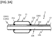
FIG. 3A is a schematic sectional view of a part of the second embodiment, illustrating an example of a hollow shaft. -
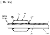
FIG. 3B is a schematic sectional view of a part of the second embodiment, illustrating an example of the hollow shaft. -
FIG. 3C is a schematic sectional view of a part of the second embodiment, illustrating an example of the hollow shaft. -
FIG. 3D is a schematic sectional view of a part of the second embodiment, illustrating an example of the hollow shaft. -
FIG. 4 is a schematic sectional view of a part of the third embodiment, illustrating an example of a balloon. -
FIG. 5 is a schematic sectional view of a part of the fourth embodiment, illustrating an example of the balloon. -
FIG. 6 is a schematic sectional view of a part of the fifth embodiment, illustrating an example of the balloon. - The balloon catheter includes a hollow shaft and an expandable and contractable balloon placed so as to cover at least a part of an outer periphery of the hollow shaft, in which the balloon has a first joint part joined to the outer periphery of the hollow shaft, a second joint part located on a proximal end side with respect to the first joint part and joined to an outer periphery of the hollow shaft, and an expandable section continuous with the first joint part and the second joint part, the first joint part is wholly located inside the expandable section, and a distal end of the first joint part is spaced apart from a distal end of the hollow shaft toward a proximal end side.
- The first to fifth embodiments of the disclosed embodiments will be explained below with reference to the figures, but the disclosed embodiments are not limited to the embodiments illustrated in the figures. The dimensions of each part illustrated in the figures are intended to facilitate understanding of the implementation and do not correspond to the actual dimensions.
-
FIG. 1 is a schematic sectional view of a whole of the first embodiment. As illustrated inFIG. 1 , aballoon catheter 1 is roughly composed of ahollow shaft 11, aballoon 21, and aconnector 31. - The
hollow shaft 11 is a shaft having a hollow shape. Thehollow shaft 11 has a through-hole (hereinafter also referred to as a "main lumen 11b") having an opening 11c on the distal end and penetrating thehollow shaft 11 from the distal end to the proximal end. For example, a medical device (not illustrated) such as a guide wire and a device for crashing thrombus, or the like is inserted into themain lumen 11b. Thehollow shaft 11 has a through-hole (hereinafter also referred to as "expansion lumen 11d") having an opening 11e that adjoins the inside of theballoon 21 described later and penetrating from the opening 11e to the proximal end of thehollow shaft 11. For example, a liquid for expanding and contracting the balloon 21 (hereinafter also referred to as "expansion liquid") passes through theexpansion lumen 11d. - The
hollow shaft 11 can be composed of e.g. a distal end-sidehollow shaft 11A located on the distal end side, and a proximal end-sidehollow shaft 11B joined to the proximal end of the distal end-sidehollow shaft 11A and extending toward the proximal end side. In theballoon catheter 1, themain lumen 11b and theexpansion lumen 11d are provided across the distal end-sidehollow shaft 11A and the proximal end-sidehollow shaft 11B. - Preferably, materials constituting the distal end-side
hollow shaft 11A and the proximal end-sidehollow shaft 11B have antithrombogenicity, flexibility and biocompatibility, because the shafts are inserted into a body cavity. For the distal end-sidehollow shaft 11A, it is possible to adopt e.g. a resin material such as a polyamide, a polyamide elastomer, a polyolefin, a polyester, a polyester elastomer, a polyurethane, a silicone, and a fluororesin, or the like. For the proximal end-sidehollow shaft 11B, it is possible to adopt e.g. a resin material having a higher rigidity than of the distal end-sidehollow shaft 11A, a metal material such as a stainless steel (SUS304, and the like) and a superelastic alloy (nickel-titanium alloy, and the like), or the like. - The
balloon 21 is an expandable and contractable member placed so as to cover at least a part of the outer periphery of thehollow shaft 11. Theballoon 21 has a firstjoint part 21a, a secondjoint part 21b, and anexpandable section 21c. Theexpandable section 21c can be expanded by injecting the expansion liquid into the inside of the balloon 21 (a space surrounded by the firstjoint part 21a, the secondjoint part 21b, theexpandable section 21c, and the outer periphery of the hollow shaft 11) through the opening 11e, so that e.g. the outer peripheral face of theballoon 21 can press an inner wall of a blood vessel or expand a constricted part. - Herein, the joint part between the
balloon 21 and thehollow shaft 11 will be explained. The firstjoint part 21a is a part where theballoon 21 is joined to the outer periphery of thehollow shaft 11. The firstjoint part 21a is wholly located inside theexpandable section 21c. In addition, the distal end of the firstjoint part 21a is spaced apart from the distal end of thehollow shaft 11 toward the proximal end side. Thus, when theballoon catheter 1 proceeds in the blood vessel, thedistal end portion 11a of the hollow shaft leads theballoon 21 in a decreased-diameter state, so that theballoon catheter 1 can be smoothly pushed forward. Specifically, for example, a distal end portion of a sheet-like member constituting theballoon 21 is turned back toward the proximal end side and this turned portion and the outer periphery of thehollow shaft 11 are joined to each other by heat welding or the like, so that the firstjoint part 21a can be formed. - The second
joint part 21b is located on the proximal end side with respect to the firstjoint part 21a, where theballoon 21 is joined to the outer periphery of thehollow shaft 11. Specifically, for example, after turning back the sheet-like member constituting theballoon 21 toward the proximal end side and joining the sheet-like member at the firstjoint part 21a, the proximal end portion of the turned portion and the outer periphery of thehollow shaft 11 are joined to each other by heat welding or the like, and thus the secondjoint part 21b can be formed. - The
expandable section 21c is continuous with the firstjoint part 21a and the secondjoint part 21b. Theexpandable section 21c is configured so as to expand radially outward and toward the distal and proximal end sides in the longitudinal axis direction by injecting the expansion liquid into theballoon 21. - The
balloon 21 can be formed of e.g. a stretchable sheet-like member. Preferably, a material constituting theballoon 21 has stretchability, ease of joining, antithrombogenicity, and biocompatibility. Examples of such a material include resin materials such as silicone and polyurethane, and the like. - The
connector 31 is an operating part where a medical device is inserted or retracted through themain lumen 11b of thehollow shaft 11 and/or where the expansion liquid is injected or removed through theexpansion lumen 11d. Theconnector 31 is connected to the proximal end of the proximal end-sidehollow shaft 11B, and includes apassage hole 31b communicating with themain lumen 11b and having anopening 31c on the proximal end side, and apassage hole 31d communicating with theexpansion lumen 11d and having anopening 31e on the proximal end side. - In relation to axial-direction lengths of each part in the
balloon catheter 1, typically, a whole length of thehollow shaft 11 is 900 mm to 2000 mm, a distance between the distal end of thehollow shaft 11 and the distal end of the firstjoint part 21a is 1 mm to 10 mm, and a distance between the distal end of the firstjoint part 21a and the proximal end of the secondjoint part 21b is 5 mm to 50mm. In relation to outer diameters of each part, typically, an outer diameter of thehollow shaft 11 is 1 mm to 5 mm, and an outer diameter of theballoon 21 is 1 mm to 6 mm in the decreased-diameter state and 2 mm to 20 mm in the increased-diameter state. In relation to an inner diameter of thehollow shaft 11, typically, an inner diameter of themain lumen 11b is 0.5 mm to 3 mm and an inner diameter of theexpansion lumen 11d is 0.1 mm to 1mm. - Next, the usage manner of the
balloon catheter 1 will be explained with reference toFIG. 1 andFIG. 2 . Herein, a procedure in which theballoon catheter 1 is a guiding catheter equipped with a balloon, and thrombus caused in a blood vessel is removed and collected, will be exemplified. - First, prior to insertion of the
balloon catheter 1, a guide wire (not illustrated), an angiographic catheter (not illustrated), and theballoon catheter 1 with theballoon 21 in a decreased-diameter state are inserted into a blood vessel. Subsequently, the balloon catheter is pushed forward till just before a part where the thrombus is formed (hereinafter, also referred to as "treatment part") while the guide wire and the angiographic catheter are advanced ahead of the balloon catheter. Subsequently, the guide wire and the angiographic catheter are removed out of the body. - Next, a thrombus collecting device is inserted from the
opening 31c of theballoon catheter 1, and a distal end side of the thrombus collecting device is advanced from theopening 11c through themain lumen 11b. Subsequently, the distal end of the thrombus collecting device is pushed forward to the treatment part. Then, an expansion liquid such as physiological saline is injected into theballoon 21 from theopening 31e through thepassage hole 31d and theexpansion lumen 11d to expand theballoon 21. At this time, in association with injection of the expansion liquid, the outer periphery of theballoon 21 abuts on an inner wall of the blood vessel to intercept the bloodstream, and theballoon 21 proceeds toward the distal end side, so that the outer periphery of thedistal end portion 11a of the hollow shaft 11 (outer periphery on the distal end side with respect to the firstjoint part 21a in the hollow shaft 11) is covered with theexpandable section 21c. - Next, the thrombus is crushed, and meanwhile the debris of the thrombus is captured and collected in the thrombus collecting device. Then, after finishing the collection of the thrombus by the thrombus collecting device, the thrombus collecting device and the balloon catheter 1 (in a state that the diameter of the balloon is decreased) are removed out of the body in this order, so that the use of the
balloon catheter 1 is completed. - Thus, since the
balloon catheter 1 has a configuration in which the whole firstjoint part 21a is located inside theexpandable section 21c, thedistal end portion 11a on the distal end side of thehollow shaft 11 can be placed so as to be exposed. Thedistal end portion 11a of theballoon catheter 1 is made of a soft material that does not damage the blood vessel inner wall even when coming into contact with the blood vessel inner wall. Thus, in the state that theballoon 21 is contracted while inserting theballoon catheter 1 into the body, thedistal end portion 11a of theballoon catheter 1 can be exposed. As a result, when inserting theballoon catheter 1 into the blood vessel, damage to the blood vessel inner wall can be suppressed. Furthermore, when theballoon 21 expands, the distal end of theexpandable section 21c can proceed to a more distal end side to cover thedistal end portion 11a of thehollow shaft 11 and the firstjoint part 21a, so that debris such as thrombus can be prevented from adhering to thedistal end portion 11a and the firstjoint part 21a. As a result, after theballoon 21 is contracted, the debris such as the thrombus can be prevented from flowing to a peripheral blood vessel. -
FIG. 3A to FIG. 3D are schematic sectional views of a part of the second embodiment. For example, as illustrated inFIG. 3A , aballoon catheter 2 is roughly composed of ahollow shaft 12, theballoon 21, and the connector 31 (not illustrated). In theballoon catheter 2, thehollow shaft 12 differs from the hollow shaft in the first embodiment. Since the configurations of theballoon 21 and theconnector 31 are the same as those in the first embodiment, the same parts are designated by the same reference numerals and detailed description thereof will be omitted. Since configurations other than the following configurations in thehollow shaft 12 and the usage manner of theballoon catheter 2 are the same as those in the first embodiment, detailed description thereof will be omitted. - The
hollow shaft 12 has a hollow shape. Thehollow shaft 12 can be composed of e.g. a distal end-sidehollow shaft 12A located on the distal end side, and a proximal end-side hollow shaft 12B (not illustrated) joined to the proximal end of the distal end-sidehollow shaft 12A and extending toward the proximal end side. In theballoon catheter 2, amain lumen 12b and anexpansion lumen 12d are provided across the distal end-sidehollow shaft 12A and the proximal end-side hollow shaft 12B. - The distal end-side
hollow shaft 12A is composed of a distal tip portion 12A1 and a distal end-side hollow shaft body 12A2. - The distal tip portion 12A1 is placed on the distal end portion of the hollow shaft. The distal tip portion 12A1 has a through-hole along the longitudinal axis direction, and this through-hole constitutes a part of the
main lumen 12b. - In a part where the distal tip portion 12A1 of the
hollow shaft 12 is placed, a proximal end of the distal tip portion 12A1 in the longitudinal direction may be located e.g. on the distal end side with respect to the firstjoint part 21a (see a distal tip portion 12A11 inFIG. 3A ), or located on the same part as the distal end of the firstjoint part 21a (see a distal tip portion 12A12 inFIG. 3B ), or located between the firstjoint part 21a and the secondjoint part 21b (see a distal tip portion 12A13 inFIG. 3C ), or located on the proximal end side with respect to the secondjoint part 21b (see a distal tip portion 12A14 inFIG. 3D ). - The distal end-side hollow shaft body 12A2 is a part whose distal end is connected to the proximal end of the distal tip portion 12A1. The distal end-side hollow shaft body 12A2 has a through-hole along the longitudinal axis direction, and this through-hole constitutes a part of the
main lumen 12b. - Herein, the
balloon catheter 2 is formed such that the distal end of thehollow shaft 12 has a hardness lower than of the proximal end of thehollow shaft 12. Specifically, theballoon catheter 2 can be formed e.g. such that the distal tip portion 12A1 has a hardness lower than of the proximal end-side hollow shaft 12B. - As a method for adjusting the hardnesses of the distal end and proximal end of the
hollow shaft 12, it is possible to adopt e.g. a method for adjusting the hardness by using the same materials having different structures such as porosity, a method using different materials having different hardnesses, a method of gradually changing the diameter of the hollow shaft, and the like. When using different materials, for example, the materials may be appropriately selected from the materials exemplified as the materials of thehollow shaft 11 in the first embodiment, on the basis of the hardness thereof. - Thus, since the
balloon catheter 2 has the aforementioned configuration, the hardness of the distal end is lower than of the proximal end in thehollow shaft 12, so that stimulation to the blood vessel or the like during advancement of theballoon catheter 2 can be reduced. -
FIG. 4 is a schematic sectional view of a part of the third embodiment. As illustrated inFIG. 4 , aballoon catheter 3 is roughly composed of thehollow shaft 12, aballoon 23, and the connector 31 (not illustrated). In theballoon catheter 3, theballoon 23 differs from the balloon in the second embodiment. Since the configurations of thehollow shaft 12 and theconnector 31 are the same as those in the second embodiment, the same parts are designated by the same reference numerals and detailed description thereof will be omitted. Since configurations other than the following configurations in theballoon 23 and the usage manner of theballoon catheter 3 are the same as those in the first embodiment, detailed description thereof will be omitted. - The
balloon 23 is an expandable and contractable member placed so as to cover at least a part of the outer periphery of thehollow shaft 12. Theballoon 23 has a firstjoint part 23a, a secondjoint part 23b, and anexpandable section 23c continuous with the firstjoint part 23a and the secondjoint part 23b. - The first
joint part 23a is joined to the outer periphery of thehollow shaft 12. The firstjoint part 23a is wholly located inside theexpandable section 23c. In addition, the distal end of the firstjoint part 23a is spaced apart from the distal end of thehollow shaft 12 toward the proximal end side. The secondjoint part 23b is located on the proximal end side with respect to the firstjoint part 23a, and joined to the outer periphery of thehollow shaft 12. Theexpandable section 23c is continuous with the firstjoint part 23a and the secondjoint part 23b. - The
balloon 23 of theballoon catheter 3 is formed such that a stretchability of a distal end portion 23c1 of theexpandable section 23c during expansion or contraction of theballoon 23 is greater than a stretchability of a proximal end portion 23c2 of theexpandable section 23c located on the proximal end side with respect to the distal end portion 23c1. Specifically, theballoon 23 can be formed e.g. such that the distal end portion 23c1 of theexpandable section 23c is folded in a bellows shape in a state where theballoon 23 is contracted (seeFIG. 4 ). When the expansion liquid is injected into theballoon 23, this bellows-like distal end portion 23c1 is expanded so as to be pushed out toward the distal end side. - In this way, since the
balloon catheter 3 has the aforementioned configuration, theexpandable section 23c can be advanced to a distal end side with respect to the firstjoint part 23a when expanding theballoon 23. As a result, it is possible to more certainly prevent debris such as thrombus from adhering to the distal end portion of thehollow shaft 12 and the joint part between theballoon 23 and thehollow shaft 12. -
FIG. 5 is a schematic sectional view of a part of the fourth embodiment. As illustrated inFIG. 5 , aballoon catheter 4 is roughly composed of thehollow shaft 12, aballoon 24, and the connector 31 (not illustrated). In theballoon catheter 4, theballoon 24 differs from the balloon in the third embodiment. Since the configurations of thehollow shaft 12 and theconnector 31 are the same as those in the second embodiment, the same parts are designated by the same reference numerals and detailed description thereof will be omitted. Since configurations other than the following configurations in theballoon 24 and the usage manner of theballoon catheter 4 are the same as those in the first embodiment, detailed description thereof will be omitted. - The
balloon 24 is an expandable and contractable member placed so as to cover at least a part of the outer periphery of thehollow shaft 12. Theballoon 24 has a firstjoint part 24a, a secondjoint part 24b, and anexpandable section 24c continuous with the firstjoint part 24a and the secondjoint part 24b. - The first
joint part 24a is joined to the outer periphery of thehollow shaft 12. The firstjoint part 24a is wholly located inside theexpandable section 24c. In addition, the distal end of the firstjoint part 24a is spaced apart from the distal end of thehollow shaft 12 toward the proximal end side. The secondjoint part 24b is located on the proximal end side with respect to the firstjoint part 24a, and joined to the outer periphery of thehollow shaft 12. Theexpandable section 24c is continuous with the firstjoint part 24a and the secondjoint part 24b. - The
balloon 24 of theballoon catheter 4 is formed such that a stretchability of a distal end portion of theexpandable section 24c during expansion or contraction of theballoon 24 is greater than a stretchability of a proximal end portion 24c2 of theexpandable section 24c located on the proximal end side with respect to a distal end portion 24c1. Specifically, in theballoon 24, for example, the members made of the same materials and having different thicknesses are connected to each other at a connection portion 24c3, and these members can form oneexpandable section 24c. In theballoon catheter 4, the thinner part 24c1 is placed on the distal end side of theexpandable section 24c, and the thicker part 24c2 is placed on the proximal end side of theexpandable section 24c. Thereby, the thinner part 24c1 is more stretchable than the thicker part 24c2, and theexpandable section 24c is expanded toward a more distal end side when injecting the expansion liquid into theballoon 24. - As a method for connecting the distal end portion 24c1 and the proximal end portion 24c2 to each other in the
expandable section 24c, it is possible to adopt e.g. a method of heat-welding resin materials to each other, or the like. - In this way, since the
balloon catheter 4 has the aforementioned configuration, theexpandable section 24c can be advanced to a distal end side with respect to the firstjoint part 24a when expanding theballoon 24. As a result, it is possible to more certainly prevent debris such as thrombus from adhering to the distal end portion of thehollow shaft 12 and the joint part between theballoon 24 and thehollow shaft 12. -
FIG. 6 is a schematic sectional view of a part of the fifth embodiment. As illustrated inFIG. 6 , aballoon catheter 5 is roughly composed of thehollow shaft 12, aballoon 25, and the connector 31 (not illustrated). In theballoon catheter 5, theballoon 25 differs from the balloon in the second embodiment. Since the configurations of thehollow shaft 12 and theconnector 31 are the same as those in the second embodiment, the same parts are designated by the same reference numerals and detailed description thereof will be omitted. Since configurations other than the following configurations in theballoon 25 and the usage manner of theballoon catheter 5 are the same as those in the first embodiment, detailed description thereof will be omitted. - The
balloon 25 is an expandable and contractable member placed so as to cover at least a part of the outer periphery of thehollow shaft 12. Theballoon 25 has a firstjoint part 25a, a secondjoint part 25b, and anexpandable section 25c continuous with the firstjoint part 25a and the secondjoint part 25b. - The first
joint part 25a is joined to the outer periphery of thehollow shaft 12. The firstjoint part 25a is wholly located inside theexpandable section 25c. In addition, the distal end of the firstjoint part 25a is spaced apart from the distal end of thehollow shaft 12 toward the proximal end side. The secondjoint part 25b is located on the proximal end side with respect to the firstjoint part 25a, and joined to the outer periphery of thehollow shaft 12. Theexpandable section 25c is continuous with the firstjoint part 25a and the secondjoint part 25b. - The
balloon 25 of theballoon catheter 5 is formed such that a flexibility of a distal end portion 25c1 in theexpandable section 25c of theballoon 25 is greater than a flexibility of a proximal end portion 25c2 in theexpandable section 25c located on the proximal end side with respect to the distal end portion 25c1. Specifically, for example, the distal end portion 25c1 and the proximal end portion 25c2 are made of different materials in theexpandable section 25c, and are connected to each other at a connection portion 25c3 to form oneexpandable section 25c, so that the flexibility of the material of the distal end portion 25c1 is greater than the flexibility of the material of the proximal end portion 25c2 (a rigidity of the material of the distal end portion 25c1 is lower than of the material of the proximal end portion 25c2). - A combination of materials used for the distal end portion 25c1 and the proximal end portion 25c2 can be appropriately selected e.g. from the materials constituting the
balloon 21 exemplified in the first embodiment on the basis of the flexibility (rigidity). - As a method for connecting the distal end portion 25c1 and the proximal end portion 25c2, it is possible to adopt e.g. the same methods as the methods for connecting the distal end portion 24c1 and the proximal end portion 24c2 of the
expandable section 24c aforementioned in the fourth embodiment, or the like. - In this way, since the
balloon catheter 5 has the aforementioned configuration, theexpandable section 25c can be advanced to a distal end side with respect to the firstjoint part 25a when expanding theballoon 25. As a result, it is possible to more certainly prevent debris such as thrombus from adhering to the distal end portion of thehollow shaft 12 and the joint part between theballoon 25 and thehollow shaft 12. - As described above, the
balloon catheters 1 to 5 make it possible to prevent debris such as thrombus from adhering to the distal end portions of thehollow shafts joint parts 21a to 25a between theballoons 21 to 25 and thehollow shafts balloon catheters 1 to 5 can be suitably applied to e.g. a guiding catheter equipped with a balloon in which a thrombus formed in a blood vessel is removed by passing a thrombus collecting device through the main lumen. - Note that the disclosed embodiments are not limited to the configurations of the aforementioned embodiments, but is stipulated by claims, and the disclosed embodiments are intended to include all modifications within the meaning and scope equivalent to those in claims.
- For example, although the
balloon catheters 1 to 5 equipped with the singlehollow shaft -
- 1 to 5
- Balloon catheter
- 11, 12
- Hollow shaft
- 21 to 25
- Balloon
- 21a to 25a
- First joint part
- 21b to 25b
- Second joint part
- 21c to 25c
- Expandable section
- 23c1, 24c1, 25c1
- Distal end portion of expandable section
- 23c2, 24c2, 25c2
- Proximal end portion of expandable section
Claims (4)
- A balloon catheter comprising:a hollow shaft; andan expandable and contractable balloon placed so as to cover at least a part of an outer periphery of the hollow shaft, whereinthe balloon comprises a first joint part joined to the outer periphery of the hollow shaft, a second joint part located on a proximal end side with respect to the first joint part and joined to the outer periphery of the hollow shaft, and an expandable section continuous with the first joint part and the second joint part,the first joint part is wholly located inside the expandable section, and a distal end of the first joint part is spaced apart from a distal end of the hollow shaft toward a proximal end side.
- The balloon catheter according to claim 1, wherein a stretchability of a distal end portion of the expandable section during expansion or contraction of the balloon is greater than a stretchability of a proximal end portion of the expandable section located on the proximal end side with respect to the distal end portion.
- The balloon catheter according to claim 1, wherein a flexibility of the distal end portion of the expandable section of the balloon is higher than a flexibility of the proximal end portion of the expandable section of the balloon located on the proximal end side with respect to the distal end portion.
- The balloon catheter according to any one of claims 1 to 3, wherein a hardness of the distal end of the hollow shaft is lower than a hardness of the proximal end of the hollow shaft.
Applications Claiming Priority (1)
| Application Number | Priority Date | Filing Date | Title |
|---|---|---|---|
| PCT/JP2019/021162 WO2020240717A1 (en) | 2019-05-28 | 2019-05-28 | Balloon catheter |
Publications (2)
| Publication Number | Publication Date |
|---|---|
| EP3978061A1 true EP3978061A1 (en) | 2022-04-06 |
| EP3978061A4 EP3978061A4 (en) | 2023-01-18 |
Family
ID=73553156
Family Applications (1)
| Application Number | Title | Priority Date | Filing Date |
|---|---|---|---|
| EP19930712.5A Withdrawn EP3978061A4 (en) | 2019-05-28 | 2019-05-28 | BALLOON CATHETER |
Country Status (5)
| Country | Link |
|---|---|
| US (1) | US20220080163A1 (en) |
| EP (1) | EP3978061A4 (en) |
| JP (1) | JP7217346B2 (en) |
| CN (1) | CN113825538B (en) |
| WO (1) | WO2020240717A1 (en) |
Families Citing this family (2)
| Publication number | Priority date | Publication date | Assignee | Title |
|---|---|---|---|---|
| WO2022210094A1 (en) * | 2021-03-29 | 2022-10-06 | 国立大学法人香川大学 | Recovery device for endoscope |
| CN116271447B (en) * | 2023-02-13 | 2025-09-09 | 深圳市擎源医疗器械有限公司 | Balloon dilation catheter |
Family Cites Families (25)
| Publication number | Priority date | Publication date | Assignee | Title |
|---|---|---|---|---|
| US4227293A (en) * | 1978-12-11 | 1980-10-14 | The Kendall Company | Method of catheter manufacture |
| SE433445B (en) * | 1981-04-16 | 1984-05-28 | Erik Gustav Percy Nordqvist | urinary catheter |
| CA1299954C (en) * | 1987-01-13 | 1992-05-05 | Yoshio Ishitsu | Balloon catheter and method of manufacturing the same |
| JP2736896B2 (en) * | 1988-07-18 | 1998-04-02 | テルモ株式会社 | Balloon catheter |
| US5192296A (en) * | 1988-08-31 | 1993-03-09 | Meadox Medicals, Inc. | Dilatation catheter |
| FR2647681A1 (en) * | 1989-05-31 | 1990-12-07 | Theron Jacques | Angioplasty apparatus for arteries |
| DK92392D0 (en) * | 1992-07-15 | 1992-07-15 | Bo Joergensen | A BALLON CATHET OR A DEVICE FOR USE WITH A BALLON CATHET |
| JP2891032B2 (en) * | 1993-03-15 | 1999-05-17 | 日本ゼオン株式会社 | Balloon catheter |
| US5976120A (en) * | 1997-05-05 | 1999-11-02 | Micro Therapeutics, Inc. | Single segment microcatheter |
| US6960222B2 (en) * | 1998-03-13 | 2005-11-01 | Gore Enterprise Holdins, Inc. | Catheter having a funnel-shaped occlusion balloon of uniform thickness and methods of manufacture |
| US6036697A (en) * | 1998-07-09 | 2000-03-14 | Scimed Life Systems, Inc. | Balloon catheter with balloon inflation at distal end of balloon |
| JPWO2005056101A1 (en) * | 2003-12-11 | 2007-12-06 | 正紀 板谷 | Balloon catheter |
| US7198632B2 (en) * | 2004-03-02 | 2007-04-03 | Boston Scientific Scimed, Inc. | Occlusion balloon catheter with longitudinally expandable balloon |
| JP2005312654A (en) * | 2004-04-28 | 2005-11-10 | Usci Japan Ltd | Multibranched pipe apparatus for introducing catheter |
| US20070088380A1 (en) * | 2005-10-14 | 2007-04-19 | Endocross Ltd. | Balloon catheter system for treating vascular occlusions |
| US20070197962A1 (en) * | 2006-02-22 | 2007-08-23 | Masuo Morikawa | Catheter for removing foreign substance in blood vessel |
| JP4457205B2 (en) | 2006-02-22 | 2010-04-28 | 医科器械 森忠 株式会社 | Intravascular foreign body removal catheter |
| US8403885B2 (en) * | 2007-12-17 | 2013-03-26 | Abbott Cardiovascular Systems Inc. | Catheter having transitioning shaft segments |
| JP5470406B2 (en) * | 2009-12-28 | 2014-04-16 | テルモ株式会社 | Balloon catheter |
| US20180311480A1 (en) * | 2011-08-20 | 2018-11-01 | Fred Göbel | Trans-anal inflow catheter for intermittently triggering a reflex-coordinated defecation |
| JP2014200371A (en) * | 2013-04-02 | 2014-10-27 | テルモ株式会社 | Balloon catheter and use method thereof |
| WO2016149272A1 (en) * | 2015-03-19 | 2016-09-22 | Boston Scientific Scimed, Inc. | Subintimal re-entry balloon catheter |
| JPWO2017111164A1 (en) * | 2015-12-24 | 2018-10-18 | 日本ゼオン株式会社 | Endoscopic treatment tool |
| WO2018033401A1 (en) * | 2016-08-17 | 2018-02-22 | Neuravi Limited | A clot retrieval system for removing occlusive clot from a blood vessel |
| AU2017254847A1 (en) * | 2016-11-28 | 2018-06-14 | Neuravi Limited | Devices and methods for removal of acute blockages from blood vessels |
-
2019
- 2019-05-28 EP EP19930712.5A patent/EP3978061A4/en not_active Withdrawn
- 2019-05-28 CN CN201980096042.0A patent/CN113825538B/en active Active
- 2019-05-28 WO PCT/JP2019/021162 patent/WO2020240717A1/en not_active Ceased
- 2019-05-28 JP JP2021521638A patent/JP7217346B2/en active Active
-
2021
- 2021-11-23 US US17/533,126 patent/US20220080163A1/en not_active Abandoned
Also Published As
| Publication number | Publication date |
|---|---|
| JP7217346B2 (en) | 2023-02-02 |
| WO2020240717A1 (en) | 2020-12-03 |
| JPWO2020240717A1 (en) | 2020-12-03 |
| CN113825538B (en) | 2023-11-17 |
| CN113825538A (en) | 2021-12-21 |
| EP3978061A4 (en) | 2023-01-18 |
| US20220080163A1 (en) | 2022-03-17 |
Similar Documents
| Publication | Publication Date | Title |
|---|---|---|
| EP0132215B1 (en) | Deflector guiding catheter | |
| JP5527850B2 (en) | Tissue penetrating apparatus and method | |
| EP3154454B1 (en) | Intravascular catheter having an expandable incising portion and drug delivery mechanism | |
| EP3505091A1 (en) | Medical device and treatment method | |
| EP2898920A1 (en) | Articulating balloon catheter and method for using the same | |
| US9326790B2 (en) | Catheter with vessel lining and methods for using same | |
| WO2017019900A1 (en) | Guide catheter extension device and methods of use for cardiology procedures | |
| CN108784897B (en) | Stent delivery system | |
| US8926559B2 (en) | Catheter with vessel lining and methods for using same | |
| WO2015146408A1 (en) | Catheter assembly and inner catheter | |
| US20220080163A1 (en) | Balloon catheter | |
| US11129964B2 (en) | Trapping sheaths and guide catheters | |
| JP5936093B2 (en) | Double lumen dilator | |
| US20060264979A1 (en) | Novel enhanced vascular surgical device | |
| CN208678150U (en) | Balloon catheter | |
| US10966697B2 (en) | Vascular closure device and method of positioning vascular closure device | |
| JP2022059506A (en) | Catheter system and catheter | |
| US10092733B2 (en) | Balloon catheter | |
| JP2016036393A (en) | Introduction assist instrument with side hole | |
| WO2015141392A1 (en) | Catheter and catheter set | |
| US20250339656A1 (en) | Medical device | |
| JP7467637B2 (en) | catheter | |
| WO2009130457A1 (en) | Expanding medical collet | |
| JP4191517B2 (en) | Dilatation balloon catheter | |
| JP2016185277A (en) | Introducer Sheath and Introducer Assembly |
Legal Events
| Date | Code | Title | Description |
|---|---|---|---|
| STAA | Information on the status of an ep patent application or granted ep patent |
Free format text: STATUS: THE INTERNATIONAL PUBLICATION HAS BEEN MADE |
|
| PUAI | Public reference made under article 153(3) epc to a published international application that has entered the european phase |
Free format text: ORIGINAL CODE: 0009012 |
|
| STAA | Information on the status of an ep patent application or granted ep patent |
Free format text: STATUS: REQUEST FOR EXAMINATION WAS MADE |
|
| 17P | Request for examination filed |
Effective date: 20211202 |
|
| AK | Designated contracting states |
Kind code of ref document: A1 Designated state(s): AL AT BE BG CH CY CZ DE DK EE ES FI FR GB GR HR HU IE IS IT LI LT LU LV MC MK MT NL NO PL PT RO RS SE SI SK SM TR |
|
| DAV | Request for validation of the european patent (deleted) | ||
| DAX | Request for extension of the european patent (deleted) | ||
| A4 | Supplementary search report drawn up and despatched |
Effective date: 20221221 |
|
| RIC1 | Information provided on ipc code assigned before grant |
Ipc: A61B 17/22 20060101ALI20221215BHEP Ipc: A61M 25/10 20130101AFI20221215BHEP |
|
| STAA | Information on the status of an ep patent application or granted ep patent |
Free format text: STATUS: EXAMINATION IS IN PROGRESS |
|
| 17Q | First examination report despatched |
Effective date: 20231107 |
|
| STAA | Information on the status of an ep patent application or granted ep patent |
Free format text: STATUS: THE APPLICATION IS DEEMED TO BE WITHDRAWN |
|
| 18D | Application deemed to be withdrawn |
Effective date: 20241029 |