WO2020240717A1 - Balloon catheter - Google Patents
Balloon catheter Download PDFInfo
- Publication number
- WO2020240717A1 WO2020240717A1 PCT/JP2019/021162 JP2019021162W WO2020240717A1 WO 2020240717 A1 WO2020240717 A1 WO 2020240717A1 JP 2019021162 W JP2019021162 W JP 2019021162W WO 2020240717 A1 WO2020240717 A1 WO 2020240717A1
- Authority
- WO
- WIPO (PCT)
- Prior art keywords
- hollow shaft
- balloon
- tip
- expansion
- joint portion
- Prior art date
Links
Images


Classifications
-
- A—HUMAN NECESSITIES
- A61—MEDICAL OR VETERINARY SCIENCE; HYGIENE
- A61M—DEVICES FOR INTRODUCING MEDIA INTO, OR ONTO, THE BODY; DEVICES FOR TRANSDUCING BODY MEDIA OR FOR TAKING MEDIA FROM THE BODY; DEVICES FOR PRODUCING OR ENDING SLEEP OR STUPOR
- A61M25/00—Catheters; Hollow probes
- A61M25/10—Balloon catheters
- A61M25/1002—Balloon catheters characterised by balloon shape
-
- A—HUMAN NECESSITIES
- A61—MEDICAL OR VETERINARY SCIENCE; HYGIENE
- A61B—DIAGNOSIS; SURGERY; IDENTIFICATION
- A61B17/00—Surgical instruments, devices or methods, e.g. tourniquets
- A61B17/32—Surgical cutting instruments
- A61B17/3205—Excision instruments
- A61B17/3207—Atherectomy devices working by cutting or abrading; Similar devices specially adapted for non-vascular obstructions
- A61B2017/320716—Atherectomy devices working by cutting or abrading; Similar devices specially adapted for non-vascular obstructions comprising means for preventing embolism by dislodged material
-
- A—HUMAN NECESSITIES
- A61—MEDICAL OR VETERINARY SCIENCE; HYGIENE
- A61M—DEVICES FOR INTRODUCING MEDIA INTO, OR ONTO, THE BODY; DEVICES FOR TRANSDUCING BODY MEDIA OR FOR TAKING MEDIA FROM THE BODY; DEVICES FOR PRODUCING OR ENDING SLEEP OR STUPOR
- A61M25/00—Catheters; Hollow probes
- A61M25/0067—Catheters; Hollow probes characterised by the distal end, e.g. tips
- A61M25/008—Strength or flexibility characteristics of the catheter tip
- A61M2025/0081—Soft tip
-
- A—HUMAN NECESSITIES
- A61—MEDICAL OR VETERINARY SCIENCE; HYGIENE
- A61M—DEVICES FOR INTRODUCING MEDIA INTO, OR ONTO, THE BODY; DEVICES FOR TRANSDUCING BODY MEDIA OR FOR TAKING MEDIA FROM THE BODY; DEVICES FOR PRODUCING OR ENDING SLEEP OR STUPOR
- A61M25/00—Catheters; Hollow probes
- A61M25/10—Balloon catheters
- A61M25/1002—Balloon catheters characterised by balloon shape
- A61M2025/1004—Balloons with folds, e.g. folded or multifolded
-
- A—HUMAN NECESSITIES
- A61—MEDICAL OR VETERINARY SCIENCE; HYGIENE
- A61M—DEVICES FOR INTRODUCING MEDIA INTO, OR ONTO, THE BODY; DEVICES FOR TRANSDUCING BODY MEDIA OR FOR TAKING MEDIA FROM THE BODY; DEVICES FOR PRODUCING OR ENDING SLEEP OR STUPOR
- A61M25/00—Catheters; Hollow probes
- A61M25/10—Balloon catheters
- A61M2025/1043—Balloon catheters with special features or adapted for special applications
- A61M2025/1065—Balloon catheters with special features or adapted for special applications having a balloon which is inversely attached to the shaft at the distal or proximal end
-
- A—HUMAN NECESSITIES
- A61—MEDICAL OR VETERINARY SCIENCE; HYGIENE
- A61M—DEVICES FOR INTRODUCING MEDIA INTO, OR ONTO, THE BODY; DEVICES FOR TRANSDUCING BODY MEDIA OR FOR TAKING MEDIA FROM THE BODY; DEVICES FOR PRODUCING OR ENDING SLEEP OR STUPOR
- A61M25/00—Catheters; Hollow probes
- A61M25/10—Balloon catheters
- A61M2025/1043—Balloon catheters with special features or adapted for special applications
- A61M2025/1068—Balloon catheters with special features or adapted for special applications having means for varying the length or diameter of the deployed balloon, this variations could be caused by excess pressure
-
- A—HUMAN NECESSITIES
- A61—MEDICAL OR VETERINARY SCIENCE; HYGIENE
- A61M—DEVICES FOR INTRODUCING MEDIA INTO, OR ONTO, THE BODY; DEVICES FOR TRANSDUCING BODY MEDIA OR FOR TAKING MEDIA FROM THE BODY; DEVICES FOR PRODUCING OR ENDING SLEEP OR STUPOR
- A61M25/00—Catheters; Hollow probes
- A61M25/10—Balloon catheters
- A61M2025/1043—Balloon catheters with special features or adapted for special applications
- A61M2025/1088—Balloon catheters with special features or adapted for special applications having special surface characteristics depending on material properties or added substances, e.g. for reducing friction
-
- A—HUMAN NECESSITIES
- A61—MEDICAL OR VETERINARY SCIENCE; HYGIENE
- A61M—DEVICES FOR INTRODUCING MEDIA INTO, OR ONTO, THE BODY; DEVICES FOR TRANSDUCING BODY MEDIA OR FOR TAKING MEDIA FROM THE BODY; DEVICES FOR PRODUCING OR ENDING SLEEP OR STUPOR
- A61M25/00—Catheters; Hollow probes
- A61M25/10—Balloon catheters
- A61M2025/1043—Balloon catheters with special features or adapted for special applications
- A61M2025/109—Balloon catheters with special features or adapted for special applications having balloons for removing solid matters, e.g. by grasping or scraping plaque, thrombus or other matters that obstruct the flow
-
- A—HUMAN NECESSITIES
- A61—MEDICAL OR VETERINARY SCIENCE; HYGIENE
- A61M—DEVICES FOR INTRODUCING MEDIA INTO, OR ONTO, THE BODY; DEVICES FOR TRANSDUCING BODY MEDIA OR FOR TAKING MEDIA FROM THE BODY; DEVICES FOR PRODUCING OR ENDING SLEEP OR STUPOR
- A61M25/00—Catheters; Hollow probes
- A61M25/10—Balloon catheters
- A61M25/1027—Making of balloon catheters
- A61M25/1034—Joining of shaft and balloon
Definitions
- the present invention relates to a balloon catheter.
- a flexible tip portion for leading the balloon may be provided on the hollow shaft. According to such a catheter, the dilated portion of the balloon guided to the tip portion can be smoothly pushed to the treatment site in the blood vessel, and damage to the blood vessel can be reduced.
- the flexible tip portion is arranged further on the tip side than the joint portion between the balloon and the hollow shaft provided at the tip of the balloon, the tip portion or the joint portion is placed during treatment.
- Debris such as an attached thrombus may peel off after the balloon contracts and flow to the periphery of the blood vessel.
- the present invention has been made based on the above circumstances, and an object of the present invention is to prevent debris such as a thrombus from adhering to the tip of a hollow shaft or the joint between a balloon and a hollow shaft. Is to provide a balloon catheter capable of.
- Hollow shaft and A balloon catheter comprising a stretchable balloon arranged so as to cover at least a part of the outer circumference of the hollow shaft.
- the balloon has a first joint portion joined to the outer circumference of the hollow shaft, and a second joint portion located on the proximal end side of the first joint portion and joined to the outer circumference of the hollow shaft. It has an extension portion that is continuous with the first joint portion and the second joint portion.
- a balloon characterized in that the entire first joint is located inside the extension and the tip of the first joint is separated from the tip of the hollow shaft toward the proximal end.
- the "tip side” means a direction along the long axis direction of the hollow shaft and a direction of traveling toward the treatment site.
- the “base end side” means a direction along the long axis direction of the hollow shaft and a direction opposite to the tip end side.
- the “tip” refers to the end portion on the distal end side of any member or portion, and the “base end” indicates the end portion on the proximal end side of any member or portion.
- the “tip portion” refers to a portion of any member or portion that includes the tip and extends halfway from the tip toward the proximal end side.
- the “base end portion” refers to a portion of any member or portion that includes the proximal end and extends halfway from the proximal end toward the distal end side.
- the present invention can provide a balloon catheter capable of preventing debris such as a thrombus from adhering to the tip of the hollow shaft or the joint between the balloon and the hollow shaft.
- the balloon catheter is a balloon catheter including a hollow shaft and a expandable / contractible balloon arranged so as to cover at least a part of the outer periphery of the hollow shaft, and the balloon is provided on the outer periphery of the hollow shaft.
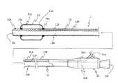
- FIG. 1 is a schematic cross-sectional view showing the entire first embodiment.
- the balloon catheter 1 is roughly composed of a hollow shaft 11, a balloon 21, and a connector 31.
- the hollow shaft 11 is a hollow shaft.
- the hollow shaft 11 has an opening 11c at the tip and a through hole (hereinafter, also referred to as “main lumen 11b”) penetrating from the tip to the base end.
- a guide wire, a medical device such as a device for crushing a thrombus, or the like (not shown) is inserted into the main lumen 11b.
- the hollow shaft 11 has an opening 11e facing the inside of the balloon 21, which will be described later, and has a through hole (hereinafter, also referred to as “expanded lumen 11d”) penetrating from the opening 11e to the base end of the hollow shaft 11.
- a liquid for expanding and contracting the balloon 21 hereinafter, also referred to as “expansion liquid” is distributed in the expansion lumen 11d.
- the hollow shaft 11 is composed of, for example, a tip side hollow shaft 11A located on the tip side and a base end side hollow shaft 11B joined to the base end of the tip end side hollow shaft 11A and extended toward the base end side. can do.
- a main lumen 11b and an expansion lumen 11d are provided over the distal end side hollow shaft 11A and the proximal end side hollow shaft 11B.
- the material constituting the distal end side hollow shaft 11A and the proximal end side hollow shaft 11B it is preferable that the material has antithrombotic property, flexibility and biocompatibility because it is inserted into the body cavity.
- the tip-side hollow shaft 11A for example, resin materials such as polyamide, polyamide elastomer, polyolefin, polyester, polyester elastomer, polyurethane, silicone, and fluororesin can be adopted.
- a resin material having a higher rigidity than the tip end side hollow shaft 11A a metal material such as stainless steel (SUS304 or the like), a superelastic alloy (nickel-titanium alloy or the like), or the like is adopted. be able to.
- the balloon 21 is a expandable / contractible member arranged so as to cover at least a part of the outer circumference of the hollow shaft 11.
- the balloon 21 has a first joint portion 21a, a second joint portion 21b, and an expansion portion 21c.
- the expansion liquid is injected into the inside of the balloon 21 (the space surrounded by the first joint portion 21a, the second joint portion 21b, the expansion portion 21c, and the outer circumference of the hollow shaft 11) through the opening 11e.
- the dilated portion 21c swells, and for example, the outer peripheral surface of the balloon 21 can be pressed against the inner wall of the blood vessel, or the constricted portion can be dilated.
- the first joint portion 21a is a portion where the balloon 21 is joined to the outer periphery of the hollow shaft 11.
- the entire first joint portion 21a is located inside the expansion portion 21c.
- the tip of the first joint portion 21a is separated from the tip of the hollow shaft 11 toward the proximal end side. Therefore, when the balloon catheter 1 advances in the blood vessel, the tip portion 11a of the hollow shaft leads the balloon 21 in the reduced diameter state, and the balloon catheter 1 can be smoothly pushed forward.
- the distal end side end portion of the sheet-shaped member constituting the balloon 21 is folded back toward the base end side, and the folded portion and the outer periphery of the hollow shaft 11 are heat-welded or the like. It can be formed by joining with.
- the second joint portion 21b is located closer to the proximal end side than the first joint portion 21a, and is a portion where the balloon 21 is joined to the outer periphery of the hollow shaft 11. Specifically, for the second joint portion 21b, for example, the base end side end portion of the sheet-shaped member constituting the balloon 21 is folded back toward the base end side, the first joint portion 21a is joined, and then the above-mentioned folded back portion 21b is formed. It can be formed by joining the end portion on the base end side of the portion and the outer periphery of the hollow shaft 11 by heat welding or the like.
- the expansion portion 21c is a portion continuous with the first joint portion 21a and the second joint portion 21b.
- the expansion portion 21c is formed so as to swell in the lateral direction of the diameter and toward the tip end side and the proximal end side of the long axis by injecting the expansion liquid into the inside of the balloon 21.
- the balloon 21 can be formed of, for example, a stretchable sheet-like member.
- the material constituting the balloon 21 preferably has elasticity, ease of joining, antithrombotic property, and biocompatibility. Examples of such a material include resin materials such as silicone and polyurethane.
- the connector 31 is an operation site for inserting and removing the medical device via the main lumen 11b of the hollow shaft 11 and / or taking in and out the expansion liquid via the expansion lumen 11d.
- the connector 31 is connected to the base end of the base end side hollow shaft 11B, has a through hole 31b having an opening 31c on the base end side which is compatible with the main lumen 11b, and an opening 31e on the base end side which is open to the expansion lumen 11d. It is provided with a through hole 31d having the above.
- each part of the balloon catheter 1 is usually 900 mm to 2000 mm for the entire hollow shaft 11, the distance between the tip of the hollow shaft 11 and the tip of the first joint 21a is 1 mm to 10 mm, and the first The distance between the tip end of the joint portion 21a and the base end of the second joint portion 21b is 5 mm to 50 mm.
- the outer diameter of each part is usually 1 mm to 5 mm for the hollow shaft 11, 1 mm to 6 mm for the balloon 21 during contraction, and 2 mm to 20 mm for the balloon 21 when the diameter is expanded.
- the inner diameter of the hollow shaft 11 is usually 0.5 mm to 3 mm for the main lumen 11b and 0.1 mm to 1 mm for the extended lumen 11d.
- the balloon catheter 1 is a guiding catheter with a balloon, and a technique for removing and recovering a thrombus generated in a blood vessel will be exemplified.
- the guide wire (not shown), the angiography catheter (not shown), and the balloon catheter 1 in which the balloon 21 is reduced in diameter are inserted into the blood vessel.
- the balloon catheter is pushed to the front of the site where the thrombus is formed (hereinafter, also referred to as “treatment site”) while leading the guide wire and the angiography catheter.
- treatment site the site where the thrombus is formed
- the thrombus collection device is inserted through the opening 31c of the balloon catheter 1, and the tip end side of the thrombus collection device is advanced from the opening 11c via the main lumen 11b.
- the tip of the thrombus collection device is then pushed to the treatment site.
- the balloon 21 is expanded by injecting an expanding solution such as physiological saline into the balloon 21 through the opening 31e through the through hole 31d and the expanding lumen 11d.
- the outer circumference of the balloon 21 abuts on the inner wall of the blood vessel to block blood flow, and the balloon 21 advances toward the tip side, so that the outer circumference of the tip 11a of the hollow shaft 11 (hollow shaft 11)
- the outer circumference on the tip side of the first joint portion 21a in the above) is covered with the expansion portion 21c.
- the balloon catheter 1 can be used by removing the thrombus collection device and the balloon catheter 1 (in a state where the balloon is reduced in diameter) from the body in this order. Complete.
- the balloon catheter 1 since the balloon catheter 1 has a configuration in which the entire first joint portion 21a is located inside the expansion portion 21c, the tip portion 11a on the distal end side of the hollow shaft 11 can be exposed and arranged. it can.
- the tip portion 11a of the balloon catheter 1 is made of a soft material that does not damage the inner wall of the blood vessel even if it comes into contact with the inner wall of the blood vessel. Therefore, in a state where the balloon 21 is contracted while the balloon catheter 1 is inserted into the body, the tip portion 11a of the balloon catheter 1 can be exposed. As a result, the balloon catheter 1 can suppress damage to the inner wall of the blood vessel when it is inserted into the blood vessel.
- the tip of the expansion portion 21c advances further toward the tip side to cover the tip portion 11a of the hollow shaft 11 and the first joint portion 21a, and debris such as a thrombus adheres to these. Can be prevented. As a result, it is possible to prevent debris such as a thrombus from flowing to the periphery of the blood vessel after the balloon 21 contracts.
- FIG. 3A-3D are schematic cross-sectional views showing a part of the second embodiment.
- the balloon catheter 2 is roughly composed of a hollow shaft 12, a balloon 21, and a connector 31 (not shown).
- the balloon catheter 2 has a hollow shaft 12 different from that of the first embodiment. Since the configurations of the balloon 21 and the connector 31 are the same as those in the first embodiment, the same parts are designated by the same reference numerals and detailed description thereof will be omitted. Further, since the configuration other than the configuration shown below in the hollow shaft 12 and the usage mode of the balloon catheter 2 are the same as those in the first embodiment, detailed description thereof will be omitted.
- the hollow shaft 12 is a hollow shaft.
- the hollow shaft 12 includes, for example, a tip side hollow shaft 12A located on the tip side and a base end side hollow shaft 12B (not shown) joined to the base end of the tip end side hollow shaft 12A and extended toward the base end side. ) And can be configured.
- a main lumen 12b and an expansion lumen 12d are provided over the distal end side hollow shaft 12A and the proximal end side hollow shaft 12B.
- the tip side hollow shaft 12A is composed of a tip tip portion 12A1 and a tip side hollow shaft main body 12A2.
- the tip tip portion 12A1 is a portion arranged at the tip portion of the hollow shaft.
- the tip tip portion 12A1 has a through hole along the long axis direction, and this through hole forms a part of the main lumen 12b.
- the base end of the tip tip portion 12A1 in the long axis direction may be located, for example, on the tip side of the first joint portion 21a.
- the base end of the tip tip portion 12A1 in the long axis direction may be located, for example, on the tip side of the first joint portion 21a.
- See tip tip 12A11 in FIG. 3A which may be the same as the tip of the first joint 21a (see tip tip 12A12 in FIG. 3B), the first joint 21a and the second joint 21b. It may be located between and (see the tip tip portion 12A13 in FIG. 3C), or may be located closer to the proximal end side than the second joint portion 21b (see the tip tip portion 12A14 in FIG. 3D).
- the tip side hollow shaft body 12A2 is a portion where the tip is connected to the base end of the tip tip portion 12A1.
- the tip-side hollow shaft body 12A2 has a through hole along the long axis direction, and this through hole forms a part of the main lumen 12b.
- the balloon catheter 2 is formed so that the hardness of the tip of the hollow shaft 12 is smaller than the hardness of the base end of the hollow shaft 12.
- the balloon catheter 2 can be formed so that, for example, the hardness of the tip end portion 12A1 is smaller than the hardness of the base end side hollow shaft 12B.
- a method for adjusting the hardness of the tip of the hollow shaft 12 and the hardness of the base end for example, a method of adjusting the hardness using the same material having a different structure such as porosity, or a method of adjusting the hardness of different materials having different hardness is used.
- a method, a method of gradually changing the diameter of the hollow shaft, or the like can be adopted.
- another different material for example, from the materials exemplified as the material of the hollow shaft 11 in the first embodiment, it may be appropriately selected based on the hardness thereof.
- the hardness of the tip of the hollow shaft 12 is smaller than the hardness of the base end of the hollow shaft 12, and the stimulation to the blood vessels and the like when the balloon catheter 2 is advanced is stimulated. Can be reduced.
- FIG. 4 is a schematic cross-sectional view showing a part of the third embodiment.
- the balloon catheter 3 is roughly composed of a hollow shaft 12, a balloon 23, and a connector 31 (not shown).
- the balloon 23 is different from that of the second embodiment. Since the configurations of the hollow shaft 12 and the connector 31 are the same as those of the second embodiment, the same parts are designated by the same reference numerals and detailed description thereof will be omitted. Further, since the configuration other than the configuration shown below in the balloon 23 and the usage mode of the balloon catheter 3 are the same as those in the first embodiment, detailed description thereof will be omitted.
- the balloon 23 is a expandable / contractible member arranged so as to cover at least a part of the outer circumference of the hollow shaft 12.
- the balloon 23 has a first joint portion 23a, a second joint portion 23b, and an expansion portion 23c continuous with the first joint portion 23a and the second joint portion 23b.
- the first joint portion 23a is joined to the outer periphery of the hollow shaft 12.
- the entire first joint portion 23a is located inside the expansion portion 23c.
- the tip of the first joint portion 23a is separated from the tip of the hollow shaft 12 toward the proximal end side.
- the second joint portion 23b is located closer to the proximal end side than the first joint portion 23a and is joined to the outer periphery of the hollow shaft 12.
- the expansion portion 23c is continuous with the first joint portion 23a and the second joint portion 23b.
- the amount of expansion and contraction of the tip portion 23c1 in the expansion portion 23c when the balloon 23 is expanded and contracted is larger than the expansion and contraction amount of the proximal end portion 23c2 located on the proximal end side of the distal end portion 23c1 in the expansion portion 23c. It is formed to be large.
- the balloon 23 can be formed, for example, so that the tip portion 23c1 of the expansion portion 23c is folded into a bellows shape when the diameter is reduced (see FIG. 4). The bellows-shaped tip portion 23c1 is deployed so as to be pushed out toward the tip side when the expanding liquid is injected into the balloon 23.
- the balloon catheter 3 has the above configuration, when the balloon 23 is expanded, the expansion portion 23c can be further advanced to the distal end side with respect to the first joint portion 23a. As a result, it is possible to more reliably prevent debris such as a thrombus from adhering to the tip of the hollow shaft 12 and the joint between the balloon 23 and the hollow shaft 12.
- FIG. 5 is a schematic cross-sectional view showing a part of the fourth embodiment.
- the balloon catheter 4 is roughly composed of a hollow shaft 12, a balloon 24, and a connector 31 (not shown).
- the balloon 24 is different from that of the third embodiment. Since the configurations of the hollow shaft 12 and the connector 31 are the same as those of the second embodiment, the same parts are designated by the same reference numerals and detailed description thereof will be omitted. Further, since the configuration other than the configuration shown below in the balloon 24 and the usage mode of the balloon catheter 4 are the same as those in the first embodiment, detailed description thereof will be omitted.
- the balloon 24 is a expandable / contractible member arranged so as to cover at least a part of the outer circumference of the hollow shaft 12.
- the balloon 24 has a first joint portion 24a, a second joint portion 24b, and an expansion portion 24c continuous with the first joint portion 24a and the second joint portion 24b.
- the first joint portion 24a is joined to the outer periphery of the hollow shaft 12.
- the entire first joint portion 24a is located inside the expansion portion 24c.
- the tip of the first joint portion 24a is separated from the tip of the hollow shaft 12 toward the proximal end side.
- the second joint portion 24b is located on the proximal end side of the first joint portion 24a and is joined to the outer periphery of the hollow shaft 12.
- the expansion portion 24c is continuous with the first joint portion 24a and the second joint portion 24b.
- the amount of expansion and contraction of the tip portion of the expansion portion 24c at the time of expansion and contraction of the balloon 24 is larger than the amount of expansion and contraction of the proximal end portion 24c2 located on the proximal end side of the expansion portion 24c. It is formed to be. Specifically, in the balloon 24, for example, members of the same material having different thicknesses are connected by a connecting portion 24c3, and one expansion portion 24c can be formed by these members. In the balloon catheter 4, a thin portion 24c1 is arranged on the distal end side of the expansion portion 24c, and a thick portion 24c2 is arranged on the proximal end side of the expansion portion 24c. Therefore, the thin portion 24c1 expands and contracts more than the thick portion 24c2, and the expansion portion 24c expands toward the tip side when the expansion liquid is injected into the balloon 24.
- a method of connecting the tip portion 24c1 and the base end portion 24c2 in the expansion portion 24c for example, a method of heat welding resin materials can be adopted.
- the balloon catheter 4 has the above configuration, when the balloon 24 is expanded, the expansion portion 24c can be further advanced to the distal end side with respect to the first joint portion 24a. As a result, it is possible to more reliably prevent debris such as a thrombus from adhering to the tip of the hollow shaft 12 or the joint between the balloon 24 and the hollow shaft 12.
- FIG. 6 is a schematic cross-sectional view showing a part of the fifth embodiment.
- the balloon catheter 5 is roughly composed of a hollow shaft 12, a balloon 25, and a connector 31 (not shown).
- the balloon 25 is different from that of the second embodiment. Since the configurations of the hollow shaft 12 and the connector 31 are the same as those of the second embodiment, the same parts are designated by the same reference numerals and detailed description thereof will be omitted. Further, since the configuration other than the configuration shown below in the balloon 25 and the usage mode of the balloon catheter 5 are the same as those in the first embodiment, detailed description thereof will be omitted.
- the balloon 25 is a expandable / contractible member arranged so as to cover at least a part of the outer circumference of the hollow shaft 12.
- the balloon 25 has a first joint portion 25a, a second joint portion 25b, and an expansion portion 25c continuous with the first joint portion 25a and the second joint portion 25b.
- the first joint portion 25a is joined to the outer periphery of the hollow shaft 12.
- the entire first joint portion 25a is located inside the expansion portion 25c.
- the tip of the first joint portion 25a is separated from the tip of the hollow shaft 12 toward the proximal end side.
- the second joint portion 25b is located closer to the proximal end side than the first joint portion 25a and is joined to the outer periphery of the hollow shaft 12.
- the expansion portion 25c is continuous with the first joint portion 25a and the second joint portion 25b.
- the flexibility of the tip portion 25c1 in the expansion portion 25c of the balloon 25 is greater than the flexibility of the proximal end portion 25c2 located on the proximal end side of the expansion portion 25c. It is formed like this. Specifically, for example, the tip portion 25c1 and the base end portion 25c2 of the expansion portion 25c formed of different materials are connected by the connection portion 25c3 to form one expansion portion 25c, and the softness of the material of the tip portion 25c1. Can be formed so as to be larger than the softness of the material of the base end portion 25c2 (the rigidity of the material of the tip end portion 25c1 is smaller than the rigidity of the material of the base end portion 25c2).
- the combination of materials used for the tip end portion 25c1 and the base end portion 25c2 can be appropriately selected from the materials constituting the balloon 21 illustrated in the first embodiment, based on flexibility (rigidity). ..
- connection method between the tip end portion 25c1 and the base end portion 25c2 for example, the same method as the connection method between the tip end portion 24c1 and the base end portion 24c2 of the expansion portion 24c described above in the fourth embodiment is adopted. Can be done.
- the balloon catheter 5 has the above configuration, when the balloon 25 is expanded, the expansion portion 25c can be further advanced to the distal end side with respect to the first joint portion 25a. As a result, it is possible to more reliably prevent debris such as a thrombus from adhering to the tip of the hollow shaft 12 and the joint between the balloon 25 and the hollow shaft 12.
- the balloon catheters 1 to 5 prevent debris such as thrombi from adhering to the tips of the hollow shafts 11 and 12 and the joints 21a to 25a between the balloons 21 to 25 and the hollow shafts 11 and 12. Since it can be prevented, for example, it can be suitably applied to a guiding catheter with a balloon that removes a thrombus formed in a blood vessel through a thrombus collecting device or the like through a main lumen.
- the balloon catheters 1 to 5 having a single hollow shafts 11 and 12 have been described, but a balloon catheter having a plurality of hollow shafts may be used, for example, with an inner hollow shaft.
- the space inside the inner hollow shaft can be used as the main lumen, and the space between the inner hollow shaft and the outer hollow shaft can be used as the expansion lumen.
Landscapes
- Health & Medical Sciences (AREA)
- Life Sciences & Earth Sciences (AREA)
- Heart & Thoracic Surgery (AREA)
- Biomedical Technology (AREA)
- Biophysics (AREA)
- Pulmonology (AREA)
- Engineering & Computer Science (AREA)
- Anesthesiology (AREA)
- Child & Adolescent Psychology (AREA)
- Hematology (AREA)
- Animal Behavior & Ethology (AREA)
- General Health & Medical Sciences (AREA)
- Public Health (AREA)
- Veterinary Medicine (AREA)
- Media Introduction/Drainage Providing Device (AREA)
- Surgical Instruments (AREA)
Abstract
The purpose of the present invention is to provide a balloon catheter capable of preventing debris such as blood clots from adhering to a distal portion of a hollow shaft and a joint between a balloon and the hollow shaft. The balloon catheter 1 is provided with a hollow shaft 11 and a balloon 21 capable of expanding and contracting and disposed to cover at least a portion of the outer circumference of the hollow shaft 11. The balloon catheter 1 is characterized in that the balloon 21 has a first joint section 21a joined to the outer circumference of the hollow shaft 11, a second joint section 21b positioned proximal to the first joint section 21a and joined to the outer circumference of the hollow shaft 11, and an expandable section 21c continuous with the first joint section 21a and the second joint section 21b, the entire first joint section 21a is positioned inside the expandable section 21c, and the distal end of the first joint section 21a is positioned proximal to and spaced apart from the distal end of the hollow shaft 11.
Description
本発明は、バルーンカテーテルに関する。
The present invention relates to a balloon catheter.
血管内に形成された血栓を取り除いたり、血管内の石灰化した部位(例えば、慢性完全閉塞:CTOなど)を治療する際、取り除いた血栓等の破片が血流に乗って血管末梢へ流れるのを防止する必要がある。かかる場合、例えば、バルーンカテーテルのバルーンを治療部位の下流側に配置し、一時的に血流を遮断することで上記破片をブロックする手法が用いられる。
When removing a blood clot formed in a blood vessel or treating a calcified site in a blood vessel (for example, chronic complete occlusion: CTO, etc.), debris such as the removed blood clot flows into the bloodstream to the periphery of the blood vessel. Need to be prevented. In such a case, for example, a method of arranging a balloon of a balloon catheter on the downstream side of the treatment site and temporarily blocking blood flow to block the fragments is used.
このようなバルーンカテーテルは、縮径状態のバルーンを治療部位まで円滑に届けるため、例えば、バルーンを先導する柔軟な先端部を中空シャフトに設けることがある。このようなカテーテルによれば、上記先端部に案内されたバルーンの拡張部を血管内の治療部位まで円滑に押し進めることができ、血管へのダメージを低減することができる。
In such a balloon catheter, in order to smoothly deliver the balloon in a reduced diameter state to the treatment site, for example, a flexible tip portion for leading the balloon may be provided on the hollow shaft. According to such a catheter, the dilated portion of the balloon guided to the tip portion can be smoothly pushed to the treatment site in the blood vessel, and damage to the blood vessel can be reduced.
しかしながら、従来のバルーンカテーテルでは、上記柔軟な先端部がバルーンの先端に設けられたバルーンと中空シャフトとの接合部よりも更に先端側に配置されるため、治療中に上記先端部や接合部に付着した血栓等の破片が、バルーン収縮後に剥がれて血管末梢へ流れる虞がある。
However, in the conventional balloon catheter, since the flexible tip portion is arranged further on the tip side than the joint portion between the balloon and the hollow shaft provided at the tip of the balloon, the tip portion or the joint portion is placed during treatment. Debris such as an attached thrombus may peel off after the balloon contracts and flow to the periphery of the blood vessel.
本発明は、以上のような事情に基づいてなされたものであり、その目的は、中空シャフトの先端部や、バルーンと中空シャフトとの接合部に血栓等の破片が付着するのを防止することが可能なバルーンカテーテルを提供することにある。
The present invention has been made based on the above circumstances, and an object of the present invention is to prevent debris such as a thrombus from adhering to the tip of a hollow shaft or the joint between a balloon and a hollow shaft. Is to provide a balloon catheter capable of.
本開示のいくつかの態様は、
(1)中空シャフトと、
前記中空シャフト外周の少なくとも一部を覆うように配置された拡縮可能なバルーンと、を備えているバルーンカテーテルであって、
前記バルーンは、前記中空シャフトの外周に接合された第1の接合部と、この第1の接合部よりも基端側に位置し前記中空シャフトの外周に接合された第2の接合部と、前記第1の接合部と前記第2の接合部とに連続する拡張部とを有し、
前記第1の接合部の全体が前記拡張部の内側に位置していると共に、前記第1の接合部の先端が前記中空シャフトの先端から基端側に離間していることを特徴とするバルーンカテーテル、
(2)前記バルーン拡縮時の前記拡張部における先端部の伸縮量が、前記拡張部における前記先端部よりも基端側に位置する基端部の伸縮量よりも大きい前記(1)に記載のバルーンカテーテル、
(3)前記バルーンの前記拡張部における先端部の柔軟性が、前記拡張部における前記先端部よりも基端側に位置する基端部の柔軟性よりも大きい前記(1)に記載のバルーンカテーテル、および
(4)前記中空シャフト先端の硬さが、前記中空シャフト基端の硬さよりも小さい前記(1)から(3)のいずれか1項に記載のバルーンカテーテル、
である。 Some aspects of this disclosure include
(1) Hollow shaft and
A balloon catheter comprising a stretchable balloon arranged so as to cover at least a part of the outer circumference of the hollow shaft.
The balloon has a first joint portion joined to the outer circumference of the hollow shaft, and a second joint portion located on the proximal end side of the first joint portion and joined to the outer circumference of the hollow shaft. It has an extension portion that is continuous with the first joint portion and the second joint portion.
A balloon characterized in that the entire first joint is located inside the extension and the tip of the first joint is separated from the tip of the hollow shaft toward the proximal end. catheter,
(2) The expansion / contraction amount of the tip portion of the expansion portion at the time of expansion / contraction of the balloon is larger than the expansion / contraction amount of the proximal end portion located on the proximal end side of the expansion portion. Balloon catheter,
(3) The balloon catheter according to (1), wherein the flexibility of the tip of the balloon at the extension is greater than the flexibility of the proximal end of the expansion, which is located closer to the proximal end than the distal end. , And (4) the balloon catheter according to any one of (1) to (3), wherein the hardness of the tip of the hollow shaft is smaller than the hardness of the base end of the hollow shaft.
Is.
なお、本明細書において、「先端側」とは、中空シャフトの長軸方向に沿う方向であって、治療部位に向って進行する方向を意味する。また、「基端側」とは、中空シャフトの長軸方向に沿う方向であって、先端側と反対の方向を意味する。また、「先端」とは、任意の部材または部位における先端側の端部、「基端」とは、任意の部材または部位における基端側の端部をそれぞれ示す。「先端部」とは、任意の部材または部位において、その先端を含みこの先端から基端側に向かって中途まで延びる部位を指す。「基端部」とは、任意の部材または部位において、その基端を含みこの基端から先端側に向かって中途まで延びる部位を指す。
In the present specification, the "tip side" means a direction along the long axis direction of the hollow shaft and a direction of traveling toward the treatment site. Further, the "base end side" means a direction along the long axis direction of the hollow shaft and a direction opposite to the tip end side. Further, the "tip" refers to the end portion on the distal end side of any member or portion, and the "base end" indicates the end portion on the proximal end side of any member or portion. The "tip portion" refers to a portion of any member or portion that includes the tip and extends halfway from the tip toward the proximal end side. The "base end portion" refers to a portion of any member or portion that includes the proximal end and extends halfway from the proximal end toward the distal end side.
本発明は、中空シャフトの先端部や、バルーンと中空シャフトとの接合部へ血栓等の破片が付着するのを防止することが可能なバルーンカテーテルを提供することができる。
The present invention can provide a balloon catheter capable of preventing debris such as a thrombus from adhering to the tip of the hollow shaft or the joint between the balloon and the hollow shaft.
当該バルーンカテーテルは、中空シャフトと、上記中空シャフト外周の少なくとも一部を覆うように配置された拡縮可能なバルーンと、を備えているバルーンカテーテルであって、上記バルーンは、上記中空シャフトの外周に接合された第1の接合部と、この第1の接合部よりも基端側に位置し上記中空シャフトの外周に接合された第2の接合部と、上記第1の接合部と上記第2の接合部とに連続する拡張部とを有し、上記第1の接合部の全体が上記拡張部の内側に位置していると共に、上記第1の接合部の先端が上記中空シャフトの先端から基端側に離間していることを特徴とすることを特徴とする。
The balloon catheter is a balloon catheter including a hollow shaft and a expandable / contractible balloon arranged so as to cover at least a part of the outer periphery of the hollow shaft, and the balloon is provided on the outer periphery of the hollow shaft. The first joint portion joined, the second joint portion located on the proximal end side of the first joint portion and joined to the outer periphery of the hollow shaft, the first joint portion and the second joint portion. It has an extension portion continuous with the joint portion of the above, the entire first joint portion is located inside the expansion portion, and the tip of the first joint portion is from the tip of the hollow shaft. It is characterized in that it is separated from the base end side.
以下、本発明の第1~第5の実施形態について図面を参照して説明するが、本発明は、当該図面に記載の実施形態にのみ限定されるものではない。また、図面に示した各部の寸法は、実施内容の理解を容易にするために示した寸法であり、実際の寸法に対応するものではない。
Hereinafter, the first to fifth embodiments of the present invention will be described with reference to the drawings, but the present invention is not limited to the embodiments described in the drawings. Further, the dimensions of each part shown in the drawings are the dimensions shown for facilitating the understanding of the implementation contents, and do not correspond to the actual dimensions.
[第1の実施形態]
図1は、第1の実施形態の全体を示す概略的断面図である。当該バルーンカテーテル1は、図1に示すように、概略的に、中空シャフト11と、バルーン21と、コネクタ31とにより構成されている。 [First Embodiment]
FIG. 1 is a schematic cross-sectional view showing the entire first embodiment. As shown in FIG. 1, theballoon catheter 1 is roughly composed of a hollow shaft 11, a balloon 21, and a connector 31.
図1は、第1の実施形態の全体を示す概略的断面図である。当該バルーンカテーテル1は、図1に示すように、概略的に、中空シャフト11と、バルーン21と、コネクタ31とにより構成されている。 [First Embodiment]
FIG. 1 is a schematic cross-sectional view showing the entire first embodiment. As shown in FIG. 1, the
中空シャフト11は、中空形状のシャフトである。中空シャフト11は、先端に開口11cを有しかつ上記先端から基端に亘って貫通する貫通孔(以下、「メインルーメン11b」ともいう)を有している。メインルーメン11bには、例えば、ガイドワイヤ、血栓等破砕用デバイスなどの医療器具等(不図示)が挿入される。また、中空シャフト11は、後述するバルーン21内部に臨む開口11eを有しかつ開口11eから中空シャフト11の基端に亘って貫通する貫通孔(以下、「拡張ルーメン11d」ともいう)を有している。拡張ルーメン11dには、例えば、バルーン21を拡縮するための液体(以下、「拡張液」ともいう)が流通する。
The hollow shaft 11 is a hollow shaft. The hollow shaft 11 has an opening 11c at the tip and a through hole (hereinafter, also referred to as “main lumen 11b”) penetrating from the tip to the base end. For example, a guide wire, a medical device such as a device for crushing a thrombus, or the like (not shown) is inserted into the main lumen 11b. Further, the hollow shaft 11 has an opening 11e facing the inside of the balloon 21, which will be described later, and has a through hole (hereinafter, also referred to as “expanded lumen 11d”) penetrating from the opening 11e to the base end of the hollow shaft 11. ing. For example, a liquid for expanding and contracting the balloon 21 (hereinafter, also referred to as “expansion liquid”) is distributed in the expansion lumen 11d.
中空シャフト11は、例えば、先端側に位置する先端側中空シャフト11Aと、この先端側中空シャフト11Aの基端に接合され基端側に向かって延設された基端側中空シャフト11Bとで構成することができる。当該バルーンカテーテル1では、先端側中空シャフト11Aと基端側中空シャフト11Bとに亘ってメインルーメン11bおよび拡張ルーメン11dが設けられている。
The hollow shaft 11 is composed of, for example, a tip side hollow shaft 11A located on the tip side and a base end side hollow shaft 11B joined to the base end of the tip end side hollow shaft 11A and extended toward the base end side. can do. In the balloon catheter 1, a main lumen 11b and an expansion lumen 11d are provided over the distal end side hollow shaft 11A and the proximal end side hollow shaft 11B.
先端側中空シャフト11Aおよび基端側中空シャフト11Bを構成する材料としては、体腔内に挿通されることから、抗血栓性、可撓性および生体適合性を有していることが好ましい。先端側中空シャフト11Aとしては、例えば、ポリアミド、ポリアミドエラストマー、ポリオレフィン、ポリエステル、ポリエステルエラストマー、ポリウレタン、シリコーン、フッ素樹脂など樹脂材料等を採用することができる。基端側中空シャフト11Bとしては、例えば、上記先端側中空シャフト11Aよりも剛性の高い樹脂材料、ステンレス鋼(SUS304など)、超弾性合金(ニッケル-チタン合金など)などの金属材料等を採用することができる。
As the material constituting the distal end side hollow shaft 11A and the proximal end side hollow shaft 11B, it is preferable that the material has antithrombotic property, flexibility and biocompatibility because it is inserted into the body cavity. As the tip-side hollow shaft 11A, for example, resin materials such as polyamide, polyamide elastomer, polyolefin, polyester, polyester elastomer, polyurethane, silicone, and fluororesin can be adopted. As the base end side hollow shaft 11B, for example, a resin material having a higher rigidity than the tip end side hollow shaft 11A, a metal material such as stainless steel (SUS304 or the like), a superelastic alloy (nickel-titanium alloy or the like), or the like is adopted. be able to.
バルーン21は、中空シャフト11外周の少なくとも一部を覆うように配置された拡縮可能な部材である。バルーン21は、第1の接合部21aと、第2の接合部21bと、拡張部21cとを有している。このバルーン21の内部(第1の接合部21aと、第2の接合部21bと、拡張部21cと、中空シャフト11の外周とにより囲まれた空間)に開口11eを介して拡張液を注入することで拡張部21cが膨らみ、例えば、バルーン21の外周面を血管の内壁に押し当てたり、狭窄部を拡張することができる。
The balloon 21 is a expandable / contractible member arranged so as to cover at least a part of the outer circumference of the hollow shaft 11. The balloon 21 has a first joint portion 21a, a second joint portion 21b, and an expansion portion 21c. The expansion liquid is injected into the inside of the balloon 21 (the space surrounded by the first joint portion 21a, the second joint portion 21b, the expansion portion 21c, and the outer circumference of the hollow shaft 11) through the opening 11e. As a result, the dilated portion 21c swells, and for example, the outer peripheral surface of the balloon 21 can be pressed against the inner wall of the blood vessel, or the constricted portion can be dilated.
ここで、バルーン21と中空シャフト11との接合部位について説明する。第1の接合部21aは、バルーン21が中空シャフト11の外周に接合された部位である。第1の接合部21aは、その全体が拡張部21cの内側に位置している。また、第1の接合部21aは、その先端が中空シャフト11の先端から基端側に離間している。このため、バルーンカテーテル1が血管内を進行する際、中空シャフトの先端部11aが縮径状態のバルーン21を先導し、バルーンカテーテル1を円滑に押し進めることができる。第1の接合部21aは、具体的には、例えば、バルーン21を構成するシート状の部材の先端側端部を基端側に折り返し、この折り返し部と中空シャフト11の外周とを加熱溶着等で接合することにより形成することができる。
Here, the joint portion between the balloon 21 and the hollow shaft 11 will be described. The first joint portion 21a is a portion where the balloon 21 is joined to the outer periphery of the hollow shaft 11. The entire first joint portion 21a is located inside the expansion portion 21c. Further, the tip of the first joint portion 21a is separated from the tip of the hollow shaft 11 toward the proximal end side. Therefore, when the balloon catheter 1 advances in the blood vessel, the tip portion 11a of the hollow shaft leads the balloon 21 in the reduced diameter state, and the balloon catheter 1 can be smoothly pushed forward. Specifically, in the first joint portion 21a, for example, the distal end side end portion of the sheet-shaped member constituting the balloon 21 is folded back toward the base end side, and the folded portion and the outer periphery of the hollow shaft 11 are heat-welded or the like. It can be formed by joining with.
第2の接合部21bは、第1の接合部21aよりも基端側に位置し、バルーン21が中空シャフト11の外周に接合された部位である。第2の接合部21bは、具体的には、例えば、バルーン21を構成するシート状の部材の基端側端部を基端側に折り返し、第1の接合部21aを接合した後、上記折り返し部の基端側の端部と中空シャフト11の外周とを加熱溶着等で接合することにより形成することができる。
The second joint portion 21b is located closer to the proximal end side than the first joint portion 21a, and is a portion where the balloon 21 is joined to the outer periphery of the hollow shaft 11. Specifically, for the second joint portion 21b, for example, the base end side end portion of the sheet-shaped member constituting the balloon 21 is folded back toward the base end side, the first joint portion 21a is joined, and then the above-mentioned folded back portion 21b is formed. It can be formed by joining the end portion on the base end side of the portion and the outer periphery of the hollow shaft 11 by heat welding or the like.
拡張部21cは、第1の接合部21aと第2の接合部21bとに連続する部位である。この拡張部21cは、拡張液がバルーン21の内部に注入されることで径外側方向、並びに長軸の先端側および基端側に膨らむように形成されている。
The expansion portion 21c is a portion continuous with the first joint portion 21a and the second joint portion 21b. The expansion portion 21c is formed so as to swell in the lateral direction of the diameter and toward the tip end side and the proximal end side of the long axis by injecting the expansion liquid into the inside of the balloon 21.
バルーン21は、例えば、伸縮可能なシート状の部材で形成することができる。バルーン21を構成する材料としては、伸縮性、接合容易性、抗血栓性および生体適合性を有していることが好ましい。このような材料としては、例えば、シリコーン、ポリウレタンなど樹脂材料等が挙げられる。
The balloon 21 can be formed of, for example, a stretchable sheet-like member. The material constituting the balloon 21 preferably has elasticity, ease of joining, antithrombotic property, and biocompatibility. Examples of such a material include resin materials such as silicone and polyurethane.
コネクタ31は、中空シャフト11のメインルーメン11bを介して医療器具を挿脱し、および/または拡張ルーメン11dを介して拡張液を出し入れする操作用の部位である。コネクタ31は、基端側中空シャフト11Bの基端に接続されており、メインルーメン11bに相通し基端側に開口31cを有する通孔31bと、拡張ルーメン11dに相通し基端側に開口31eを有する通孔31dとを備えている。
The connector 31 is an operation site for inserting and removing the medical device via the main lumen 11b of the hollow shaft 11 and / or taking in and out the expansion liquid via the expansion lumen 11d. The connector 31 is connected to the base end of the base end side hollow shaft 11B, has a through hole 31b having an opening 31c on the base end side which is compatible with the main lumen 11b, and an opening 31e on the base end side which is open to the expansion lumen 11d. It is provided with a through hole 31d having the above.
当該バルーンカテーテル1における各部の軸方向の長さは、通常、中空シャフト11全体が900mm~2000mm、中空シャフト11の先端と第1の接合部21aの先端との距離が1mm~10mm、第1の接合部21aの先端と第2の接合部21bの基端との距離が5mm~50mmである。各部の外径は、通常、中空シャフト11が1mm~5mm、縮経時のバルーン21が1mm~6mm、拡径時のバルーン21が2mm~20mmである。中空シャフト11の内径は、通常、メインルーメン11bが0.5mm~3mm、拡張ルーメン11dが0.1mm~1mmである。
The axial length of each part of the balloon catheter 1 is usually 900 mm to 2000 mm for the entire hollow shaft 11, the distance between the tip of the hollow shaft 11 and the tip of the first joint 21a is 1 mm to 10 mm, and the first The distance between the tip end of the joint portion 21a and the base end of the second joint portion 21b is 5 mm to 50 mm. The outer diameter of each part is usually 1 mm to 5 mm for the hollow shaft 11, 1 mm to 6 mm for the balloon 21 during contraction, and 2 mm to 20 mm for the balloon 21 when the diameter is expanded. The inner diameter of the hollow shaft 11 is usually 0.5 mm to 3 mm for the main lumen 11b and 0.1 mm to 1 mm for the extended lumen 11d.
次に、当該バルーンカテーテル1の使用態様について、図1、図2を参照して説明する。ここでは、バルーンカテーテル1がバルーン付きガイディングカテーテルであり、血管内に生じた血栓を除去して回収する手技について例示する。
Next, the usage mode of the balloon catheter 1 will be described with reference to FIGS. 1 and 2. Here, the balloon catheter 1 is a guiding catheter with a balloon, and a technique for removing and recovering a thrombus generated in a blood vessel will be exemplified.
まず、当該バルーンカテーテル1の挿入に先立って、ガイドワイヤ(不図示)、血管造影用カテーテル(不図示)、バルーン21が縮径した状態のバルーンカテーテル1を血管内に挿入する。次いで、ガイドワイヤおよび血管造影用カテーテルを先行させながらバルーンカテーテルを血栓が形成されている部位(以下、「治療部位」ともいう)の手前まで推し進める。次いで、ガイドワイヤおよび血管造影用カテーテルを体外へ除去する。
First, prior to the insertion of the balloon catheter 1, the guide wire (not shown), the angiography catheter (not shown), and the balloon catheter 1 in which the balloon 21 is reduced in diameter are inserted into the blood vessel. Next, the balloon catheter is pushed to the front of the site where the thrombus is formed (hereinafter, also referred to as “treatment site”) while leading the guide wire and the angiography catheter. The guide wire and angiography catheter are then removed from the body.
次に、血栓回収器具を当該バルーンカテーテル1の開口31cから挿入し、メインルーメン11bを介して血栓回収器具の先端側を開口11cから進出させる。次いで、血栓回収器具の先端を治療部位まで押し進める。次に、開口31eから通孔31dおよび拡張ルーメン11dを介して生理食塩水などの拡張液をバルーン21内に注入することでバルーン21を拡張する。この際、拡張液の注入に伴い、バルーン21の外周が血管内壁に当接して血流を遮断すると共に、バルーン21が先端側へ進出することで中空シャフト11の先端部11a外周(中空シャフト11における第1の接合部21aよりも先端側の外周)が拡張部21cで覆われる。
Next, the thrombus collection device is inserted through the opening 31c of the balloon catheter 1, and the tip end side of the thrombus collection device is advanced from the opening 11c via the main lumen 11b. The tip of the thrombus collection device is then pushed to the treatment site. Next, the balloon 21 is expanded by injecting an expanding solution such as physiological saline into the balloon 21 through the opening 31e through the through hole 31d and the expanding lumen 11d. At this time, as the expanding liquid is injected, the outer circumference of the balloon 21 abuts on the inner wall of the blood vessel to block blood flow, and the balloon 21 advances toward the tip side, so that the outer circumference of the tip 11a of the hollow shaft 11 (hollow shaft 11) The outer circumference on the tip side of the first joint portion 21a in the above) is covered with the expansion portion 21c.
次に、血栓を破砕しながらその破片を血栓回収器具に取り込んで回収する。次いで、血栓回収器具による血栓の回収が終了した後、血栓回収器具、当該バルーンカテーテル1(バルーンが縮径されている状態)の順番でこれらを体外に抜去することで当該バルーンカテーテル1の使用が完了する。
Next, while crushing the thrombus, the debris is taken into the thrombus collection device and collected. Next, after the collection of the thrombus by the thrombus collection device is completed, the balloon catheter 1 can be used by removing the thrombus collection device and the balloon catheter 1 (in a state where the balloon is reduced in diameter) from the body in this order. Complete.
このように、当該バルーンカテーテル1は、第1の接合部21aの全体が拡張部21cの内側に位置する構成であるので、中空シャフト11の先端側の先端部11aを露出して配置することができる。バルーンカテーテル1の先端部11aは血管内壁と接触をしても血管内壁を損傷させない軟質材料で形成されている。このため、当該バルーンカテーテル1を体内に挿入する間のバルーン21が収縮している状態においては、バルーンカテーテル1の先端部11aを露出させることができる。その結果、当該バルーンカテーテル1は血管内への挿入の際、血管内壁の損傷を抑制することができる。さらにバルーン21が拡張する際、拡張部21cの先端がより先端側に進出して中空シャフト11の先端部11aや第1の接合部21aを覆うことができ、これらに血栓等の破片が付着するのを防止することができる。その結果、バルーン21収縮後に血栓等の破片が血管末梢へ流れるのを抑制することができる。
As described above, since the balloon catheter 1 has a configuration in which the entire first joint portion 21a is located inside the expansion portion 21c, the tip portion 11a on the distal end side of the hollow shaft 11 can be exposed and arranged. it can. The tip portion 11a of the balloon catheter 1 is made of a soft material that does not damage the inner wall of the blood vessel even if it comes into contact with the inner wall of the blood vessel. Therefore, in a state where the balloon 21 is contracted while the balloon catheter 1 is inserted into the body, the tip portion 11a of the balloon catheter 1 can be exposed. As a result, the balloon catheter 1 can suppress damage to the inner wall of the blood vessel when it is inserted into the blood vessel. Further, when the balloon 21 expands, the tip of the expansion portion 21c advances further toward the tip side to cover the tip portion 11a of the hollow shaft 11 and the first joint portion 21a, and debris such as a thrombus adheres to these. Can be prevented. As a result, it is possible to prevent debris such as a thrombus from flowing to the periphery of the blood vessel after the balloon 21 contracts.
[第2の実施形態]
図3A~図3Dは、第2の実施形態の一部を示す概略的断面図である。当該バルーンカテーテル2は、例えば図3Aに示すように、概略的に、中空シャフト12と、バルーン21と、コネクタ31(不図示)とにより構成されている。当該バルーンカテーテル2は、中空シャフト12が第1の実施形態のものと異なっている。なお、バルーン21およびコネクタ31の構成は、第1の実施形態と同様であるので、同一部分には同一符号を付してその詳細な説明を省略する。また、中空シャフト12における以下に示す構成以外の構成、並びに当該バルーンカテーテル2の使用態様は、第1の実施形態と同様であるので、その詳細な説明を省略する。 [Second Embodiment]
3A-3D are schematic cross-sectional views showing a part of the second embodiment. As shown in FIG. 3A, for example, theballoon catheter 2 is roughly composed of a hollow shaft 12, a balloon 21, and a connector 31 (not shown). The balloon catheter 2 has a hollow shaft 12 different from that of the first embodiment. Since the configurations of the balloon 21 and the connector 31 are the same as those in the first embodiment, the same parts are designated by the same reference numerals and detailed description thereof will be omitted. Further, since the configuration other than the configuration shown below in the hollow shaft 12 and the usage mode of the balloon catheter 2 are the same as those in the first embodiment, detailed description thereof will be omitted.
図3A~図3Dは、第2の実施形態の一部を示す概略的断面図である。当該バルーンカテーテル2は、例えば図3Aに示すように、概略的に、中空シャフト12と、バルーン21と、コネクタ31(不図示)とにより構成されている。当該バルーンカテーテル2は、中空シャフト12が第1の実施形態のものと異なっている。なお、バルーン21およびコネクタ31の構成は、第1の実施形態と同様であるので、同一部分には同一符号を付してその詳細な説明を省略する。また、中空シャフト12における以下に示す構成以外の構成、並びに当該バルーンカテーテル2の使用態様は、第1の実施形態と同様であるので、その詳細な説明を省略する。 [Second Embodiment]
3A-3D are schematic cross-sectional views showing a part of the second embodiment. As shown in FIG. 3A, for example, the
中空シャフト12は、中空形状のシャフトである。中空シャフト12は、例えば、先端側に位置する先端側中空シャフト12Aと、この先端側中空シャフト12Aの基端に接合され基端側に向かって延設された基端側中空シャフト12B(不図示)とで構成することができる。当該バルーンカテーテル2では、先端側中空シャフト12Aと基端側中空シャフト12Bとに亘ってメインルーメン12bおよび拡張ルーメン12dが設けられている。
The hollow shaft 12 is a hollow shaft. The hollow shaft 12 includes, for example, a tip side hollow shaft 12A located on the tip side and a base end side hollow shaft 12B (not shown) joined to the base end of the tip end side hollow shaft 12A and extended toward the base end side. ) And can be configured. In the balloon catheter 2, a main lumen 12b and an expansion lumen 12d are provided over the distal end side hollow shaft 12A and the proximal end side hollow shaft 12B.
先端側中空シャフト12Aは、先端チップ部12A1と、先端側中空シャフト本体12A2とにより構成されている。
The tip side hollow shaft 12A is composed of a tip tip portion 12A1 and a tip side hollow shaft main body 12A2.
先端チップ部12A1は、中空シャフトの先端部に配置された部位である。先端チップ部12A1は、長軸方向に沿って貫通孔を有しており、この貫通孔がメインルーメン12bの一部を構成している。
The tip tip portion 12A1 is a portion arranged at the tip portion of the hollow shaft. The tip tip portion 12A1 has a through hole along the long axis direction, and this through hole forms a part of the main lumen 12b.
中空シャフト12のうちの先端チップ部12A1が配置される部位としては、長軸方向における先端チップ部12A1の基端が、例えば、第1の接合部21aよりも先端側に位置していてもよく(図3Aの先端チップ部12A11参照)、第1の接合部21aの先端と同じであってもよく(図3Bの先端チップ部12A12参照)、第1の接合部21aと第2の接合部21bとの間に位置していてもよく(図3Cの先端チップ部12A13参照)、第2の接合部21bよりも基端側に位置していてもよい(図3Dの先端チップ部12A14参照)。
As a portion of the hollow shaft 12 where the tip tip portion 12A1 is arranged, the base end of the tip tip portion 12A1 in the long axis direction may be located, for example, on the tip side of the first joint portion 21a. (See tip tip 12A11 in FIG. 3A), which may be the same as the tip of the first joint 21a (see tip tip 12A12 in FIG. 3B), the first joint 21a and the second joint 21b. It may be located between and (see the tip tip portion 12A13 in FIG. 3C), or may be located closer to the proximal end side than the second joint portion 21b (see the tip tip portion 12A14 in FIG. 3D).
先端側中空シャフト本体12A2は、先端が先端チップ部12A1の基端に接続された部位である。先端側中空シャフト本体12A2は、長軸方向に沿って貫通孔を有しており、この貫通孔がメインルーメン12bの一部を構成している。
The tip side hollow shaft body 12A2 is a portion where the tip is connected to the base end of the tip tip portion 12A1. The tip-side hollow shaft body 12A2 has a through hole along the long axis direction, and this through hole forms a part of the main lumen 12b.
ここで、当該バルーンカテーテル2は、中空シャフト12先端の硬さが、中空シャフト12基端の硬さよりも小さくなるように形成されている。具体的には、当該バルーンカテーテル2は、例えば、先端チップ部12A1の硬さが、基端側中空シャフト12Bの硬さよりも小さくなるよう形成することができる。
Here, the balloon catheter 2 is formed so that the hardness of the tip of the hollow shaft 12 is smaller than the hardness of the base end of the hollow shaft 12. Specifically, the balloon catheter 2 can be formed so that, for example, the hardness of the tip end portion 12A1 is smaller than the hardness of the base end side hollow shaft 12B.
中空シャフト12先端の硬さおよび基端の硬さの調整方法としては、例えば、多孔度などの構造が異なる同一材料を用いて硬さを調整する方法、硬さが異なる別異の材料を用いる方法、中空シャフトの径を徐変させる方法等を採用することができる。別異の材料を用いる場合、例えば、第1の実施形態にて中空シャフト11の材料として例示したものの中から、その硬さに基づいて適宜選択するようにしてもよい。
As a method for adjusting the hardness of the tip of the hollow shaft 12 and the hardness of the base end, for example, a method of adjusting the hardness using the same material having a different structure such as porosity, or a method of adjusting the hardness of different materials having different hardness is used. A method, a method of gradually changing the diameter of the hollow shaft, or the like can be adopted. When another different material is used, for example, from the materials exemplified as the material of the hollow shaft 11 in the first embodiment, it may be appropriately selected based on the hardness thereof.
このように、当該バルーンカテーテル2は、上記構成であるので、中空シャフト12先端の硬さが、中空シャフト12基端の硬さよりも小さい分、バルーンカテーテル2を前進する際の血管等への刺激を低減することができる。
As described above, since the balloon catheter 2 has the above configuration, the hardness of the tip of the hollow shaft 12 is smaller than the hardness of the base end of the hollow shaft 12, and the stimulation to the blood vessels and the like when the balloon catheter 2 is advanced is stimulated. Can be reduced.
[第3の実施形態]
図4は、第3の実施形態の一部を示す概略的断面図である。当該バルーンカテーテル3は、図4に示すように、概略的に、中空シャフト12と、バルーン23と、コネクタ31(不図示)とにより構成されている。当該バルーンカテーテル3は、バルーン23が第2の実施形態のものと異なっている。なお、中空シャフト12およびコネクタ31の構成は、第2の実施形態と同様であるので、同一部分には同一符号を付してその詳細な説明を省略する。また、バルーン23における以下に示す構成以外の構成、並びに当該バルーンカテーテル3の使用態様は、第1の実施形態と同様であるので、その詳細な説明を省略する。 [Third Embodiment]
FIG. 4 is a schematic cross-sectional view showing a part of the third embodiment. As shown in FIG. 4, theballoon catheter 3 is roughly composed of a hollow shaft 12, a balloon 23, and a connector 31 (not shown). In the balloon catheter 3, the balloon 23 is different from that of the second embodiment. Since the configurations of the hollow shaft 12 and the connector 31 are the same as those of the second embodiment, the same parts are designated by the same reference numerals and detailed description thereof will be omitted. Further, since the configuration other than the configuration shown below in the balloon 23 and the usage mode of the balloon catheter 3 are the same as those in the first embodiment, detailed description thereof will be omitted.
図4は、第3の実施形態の一部を示す概略的断面図である。当該バルーンカテーテル3は、図4に示すように、概略的に、中空シャフト12と、バルーン23と、コネクタ31(不図示)とにより構成されている。当該バルーンカテーテル3は、バルーン23が第2の実施形態のものと異なっている。なお、中空シャフト12およびコネクタ31の構成は、第2の実施形態と同様であるので、同一部分には同一符号を付してその詳細な説明を省略する。また、バルーン23における以下に示す構成以外の構成、並びに当該バルーンカテーテル3の使用態様は、第1の実施形態と同様であるので、その詳細な説明を省略する。 [Third Embodiment]
FIG. 4 is a schematic cross-sectional view showing a part of the third embodiment. As shown in FIG. 4, the
バルーン23は、中空シャフト12外周の少なくとも一部を覆うように配置された拡縮可能な部材である。バルーン23は、第1の接合部23aと、第2の接合部23bと、第1の接合部23aと第2の接合部23bとに連続する拡張部23cとを有している。
The balloon 23 is a expandable / contractible member arranged so as to cover at least a part of the outer circumference of the hollow shaft 12. The balloon 23 has a first joint portion 23a, a second joint portion 23b, and an expansion portion 23c continuous with the first joint portion 23a and the second joint portion 23b.
第1の接合部23aは、中空シャフト12の外周に接合されている。第1の接合部23aは、その全体が拡張部23cの内側に位置している。また、第1の接合部23aは、第1の接合部23aの先端が中空シャフト12の先端から基端側に離間している。第2の接合部23bは、第1の接合部23aよりも基端側に位置し、中空シャフト12の外周に接合されている。拡張部23cは、第1の接合部23aと第2の接合部23bとに連続している。
The first joint portion 23a is joined to the outer periphery of the hollow shaft 12. The entire first joint portion 23a is located inside the expansion portion 23c. Further, in the first joint portion 23a, the tip of the first joint portion 23a is separated from the tip of the hollow shaft 12 toward the proximal end side. The second joint portion 23b is located closer to the proximal end side than the first joint portion 23a and is joined to the outer periphery of the hollow shaft 12. The expansion portion 23c is continuous with the first joint portion 23a and the second joint portion 23b.
当該バルーンカテーテル3のバルーン23は、バルーン23拡縮時の拡張部23cにおける先端部23c1の伸縮量が、拡張部23cにおける先端部23c1よりも基端側に位置する基端部23c2の伸縮量よりも大きくなるように形成されている。具体的には、バルーン23は、例えば、縮径時において拡張部23cの先端部23c1が蛇腹状に折り込まれるように形成することができる(図4参照)。この蛇腹状の先端部23c1は、バルーン23内部に拡張液を注入する際に先端側に押し出されるように展開する。
In the balloon 23 of the balloon catheter 3, the amount of expansion and contraction of the tip portion 23c1 in the expansion portion 23c when the balloon 23 is expanded and contracted is larger than the expansion and contraction amount of the proximal end portion 23c2 located on the proximal end side of the distal end portion 23c1 in the expansion portion 23c. It is formed to be large. Specifically, the balloon 23 can be formed, for example, so that the tip portion 23c1 of the expansion portion 23c is folded into a bellows shape when the diameter is reduced (see FIG. 4). The bellows-shaped tip portion 23c1 is deployed so as to be pushed out toward the tip side when the expanding liquid is injected into the balloon 23.
このように、当該バルーンカテーテル3は、上記構成であるので、バルーン23を拡張する際、第1の接合部23aに対してより一層先端側に拡張部23cを進出させることができる。その結果、中空シャフト12の先端部や、バルーン23と中空シャフト12との接合部へ血栓等の破片が付着するのをより確実に防止することができる。
As described above, since the balloon catheter 3 has the above configuration, when the balloon 23 is expanded, the expansion portion 23c can be further advanced to the distal end side with respect to the first joint portion 23a. As a result, it is possible to more reliably prevent debris such as a thrombus from adhering to the tip of the hollow shaft 12 and the joint between the balloon 23 and the hollow shaft 12.
[第4の実施形態]
図5は、第4の実施形態の一部を示す概略的断面図である。当該バルーンカテーテル4は、図5に示すように、概略的に、中空シャフト12と、バルーン24と、コネクタ31(不図示)とにより構成されている。当該バルーンカテーテル4は、バルーン24が第3の実施形態のものと異なっている。なお、中空シャフト12およびコネクタ31の構成は、第2の実施形態と同様であるので、同一部分には同一符号を付してその詳細な説明を省略する。また、バルーン24における以下に示す構成以外の構成、並びに当該バルーンカテーテル4の使用態様は、第1の実施形態と同様であるので、その詳細な説明を省略する。 [Fourth Embodiment]
FIG. 5 is a schematic cross-sectional view showing a part of the fourth embodiment. As shown in FIG. 5, theballoon catheter 4 is roughly composed of a hollow shaft 12, a balloon 24, and a connector 31 (not shown). In the balloon catheter 4, the balloon 24 is different from that of the third embodiment. Since the configurations of the hollow shaft 12 and the connector 31 are the same as those of the second embodiment, the same parts are designated by the same reference numerals and detailed description thereof will be omitted. Further, since the configuration other than the configuration shown below in the balloon 24 and the usage mode of the balloon catheter 4 are the same as those in the first embodiment, detailed description thereof will be omitted.
図5は、第4の実施形態の一部を示す概略的断面図である。当該バルーンカテーテル4は、図5に示すように、概略的に、中空シャフト12と、バルーン24と、コネクタ31(不図示)とにより構成されている。当該バルーンカテーテル4は、バルーン24が第3の実施形態のものと異なっている。なお、中空シャフト12およびコネクタ31の構成は、第2の実施形態と同様であるので、同一部分には同一符号を付してその詳細な説明を省略する。また、バルーン24における以下に示す構成以外の構成、並びに当該バルーンカテーテル4の使用態様は、第1の実施形態と同様であるので、その詳細な説明を省略する。 [Fourth Embodiment]
FIG. 5 is a schematic cross-sectional view showing a part of the fourth embodiment. As shown in FIG. 5, the
バルーン24は、中空シャフト12外周の少なくとも一部を覆うように配置された拡縮可能な部材である。バルーン24は、第1の接合部24aと、第2の接合部24bと、第1の接合部24aと第2の接合部24bとに連続する拡張部24cとを有している。
The balloon 24 is a expandable / contractible member arranged so as to cover at least a part of the outer circumference of the hollow shaft 12. The balloon 24 has a first joint portion 24a, a second joint portion 24b, and an expansion portion 24c continuous with the first joint portion 24a and the second joint portion 24b.
第1の接合部24aは、中空シャフト12の外周に接合されている。第1の接合部24aは、その全体が拡張部24cの内側に位置している。また、第1の接合部24aは、第1の接合部24aの先端が中空シャフト12の先端から基端側に離間している。第2の接合部24bは、第1の接合部24aよりも基端側に位置し、中空シャフト12の外周に接合されている。拡張部24cは、第1の接合部24aと第2の接合部24bとに連続している。
The first joint portion 24a is joined to the outer periphery of the hollow shaft 12. The entire first joint portion 24a is located inside the expansion portion 24c. Further, in the first joint portion 24a, the tip of the first joint portion 24a is separated from the tip of the hollow shaft 12 toward the proximal end side. The second joint portion 24b is located on the proximal end side of the first joint portion 24a and is joined to the outer periphery of the hollow shaft 12. The expansion portion 24c is continuous with the first joint portion 24a and the second joint portion 24b.
当該バルーンカテーテル4のバルーン24は、バルーン24拡縮時の拡張部24cにおける先端部の伸縮量が、拡張部24cにおける先端部24c1よりも基端側に位置する基端部24c2の伸縮量よりも大きくなるように形成されている。具体的には、バルーン24は、例えば、厚みの異なる同じ材料の部材どうしが接続部24c3にて接続され、これらの部材により一つの拡張部24cを形成することができる。当該バルーンカテーテル4では、拡張部24cの先端側に厚みの薄い部位24c1、拡張部24cの基端側に厚みの厚い部位24c2が配置されている。このため、厚みの薄い部位24c1が厚みの厚い部位24c2に比べてより伸縮し、バルーン24内部に拡張液を注入する際に拡張部24cがより先端側に展開する。
In the balloon 24 of the balloon catheter 4, the amount of expansion and contraction of the tip portion of the expansion portion 24c at the time of expansion and contraction of the balloon 24 is larger than the amount of expansion and contraction of the proximal end portion 24c2 located on the proximal end side of the expansion portion 24c. It is formed to be. Specifically, in the balloon 24, for example, members of the same material having different thicknesses are connected by a connecting portion 24c3, and one expansion portion 24c can be formed by these members. In the balloon catheter 4, a thin portion 24c1 is arranged on the distal end side of the expansion portion 24c, and a thick portion 24c2 is arranged on the proximal end side of the expansion portion 24c. Therefore, the thin portion 24c1 expands and contracts more than the thick portion 24c2, and the expansion portion 24c expands toward the tip side when the expansion liquid is injected into the balloon 24.
拡張部24cにおける先端部24c1と基端部24c2との接続方法としては、例えば、樹脂材料どうしを加熱溶着する方法等を採用することができる。
As a method of connecting the tip portion 24c1 and the base end portion 24c2 in the expansion portion 24c, for example, a method of heat welding resin materials can be adopted.
このように、当該バルーンカテーテル4は、上記構成であるので、バルーン24を拡張する際、第1の接合部24aに対してより一層先端側に拡張部24cを進出させることができる。その結果、中空シャフト12の先端部や、バルーン24と中空シャフト12との接合部へ血栓等の破片が付着するのをより確実に防止することができる。
As described above, since the balloon catheter 4 has the above configuration, when the balloon 24 is expanded, the expansion portion 24c can be further advanced to the distal end side with respect to the first joint portion 24a. As a result, it is possible to more reliably prevent debris such as a thrombus from adhering to the tip of the hollow shaft 12 or the joint between the balloon 24 and the hollow shaft 12.
[第5の実施形態]
図6は、第5の実施形態の一部を示す概略的断面図である。当該バルーンカテーテル5は、図6に示すように、概略的に、中空シャフト12と、バルーン25と、コネクタ31(不図示)とにより構成されている。当該バルーンカテーテル5は、バルーン25が第2の実施形態のものと異なっている。なお、中空シャフト12およびコネクタ31の構成は、第2の実施形態と同様であるので、同一部分には同一符号を付してその詳細な説明を省略する。また、バルーン25における以下に示す構成以外の構成、並びに当該バルーンカテーテル5の使用態様は、第1の実施形態と同様であるので、その詳細な説明を省略する。 [Fifth Embodiment]
FIG. 6 is a schematic cross-sectional view showing a part of the fifth embodiment. As shown in FIG. 6, theballoon catheter 5 is roughly composed of a hollow shaft 12, a balloon 25, and a connector 31 (not shown). In the balloon catheter 5, the balloon 25 is different from that of the second embodiment. Since the configurations of the hollow shaft 12 and the connector 31 are the same as those of the second embodiment, the same parts are designated by the same reference numerals and detailed description thereof will be omitted. Further, since the configuration other than the configuration shown below in the balloon 25 and the usage mode of the balloon catheter 5 are the same as those in the first embodiment, detailed description thereof will be omitted.
図6は、第5の実施形態の一部を示す概略的断面図である。当該バルーンカテーテル5は、図6に示すように、概略的に、中空シャフト12と、バルーン25と、コネクタ31(不図示)とにより構成されている。当該バルーンカテーテル5は、バルーン25が第2の実施形態のものと異なっている。なお、中空シャフト12およびコネクタ31の構成は、第2の実施形態と同様であるので、同一部分には同一符号を付してその詳細な説明を省略する。また、バルーン25における以下に示す構成以外の構成、並びに当該バルーンカテーテル5の使用態様は、第1の実施形態と同様であるので、その詳細な説明を省略する。 [Fifth Embodiment]
FIG. 6 is a schematic cross-sectional view showing a part of the fifth embodiment. As shown in FIG. 6, the
バルーン25は、中空シャフト12外周の少なくとも一部を覆うように配置された拡縮可能な部材である。バルーン25は、第1の接合部25aと、第2の接合部25bと、第1の接合部25aと第2の接合部25bとに連続する拡張部25cとを有している。
The balloon 25 is a expandable / contractible member arranged so as to cover at least a part of the outer circumference of the hollow shaft 12. The balloon 25 has a first joint portion 25a, a second joint portion 25b, and an expansion portion 25c continuous with the first joint portion 25a and the second joint portion 25b.
第1の接合部25aは、中空シャフト12の外周に接合されている。第1の接合部25aは、その全体が拡張部25cの内側に位置している。また、第1の接合部25aは、第1の接合部25aの先端が中空シャフト12の先端から基端側に離間している。第2の接合部25bは、第1の接合部25aよりも基端側に位置し、中空シャフト12の外周に接合されている。拡張部25cは、第1の接合部25aと第2の接合部25bとに連続している。
The first joint portion 25a is joined to the outer periphery of the hollow shaft 12. The entire first joint portion 25a is located inside the expansion portion 25c. Further, in the first joint portion 25a, the tip of the first joint portion 25a is separated from the tip of the hollow shaft 12 toward the proximal end side. The second joint portion 25b is located closer to the proximal end side than the first joint portion 25a and is joined to the outer periphery of the hollow shaft 12. The expansion portion 25c is continuous with the first joint portion 25a and the second joint portion 25b.
当該バルーンカテーテル5のバルーン25は、バルーン25の拡張部25cにおける先端部25c1の柔軟性が、拡張部25cにおける先端部25c1よりも基端側に位置する基端部25c2の柔軟性よりも大きくなるように形成されている。具体的には、例えば、異なる材料で形成した拡張部25cの先端部25c1と基端部25c2とを接続部25c3で接続して一つの拡張部25cを形成し、先端部25c1の材料の柔らかさが基端部25c2の材料の柔らかさよりも大きくなる(先端部25c1の材料の剛性が基端部25c2の材料の剛性よりも小さくなる)ように形成することができる。
In the balloon 25 of the balloon catheter 5, the flexibility of the tip portion 25c1 in the expansion portion 25c of the balloon 25 is greater than the flexibility of the proximal end portion 25c2 located on the proximal end side of the expansion portion 25c. It is formed like this. Specifically, for example, the tip portion 25c1 and the base end portion 25c2 of the expansion portion 25c formed of different materials are connected by the connection portion 25c3 to form one expansion portion 25c, and the softness of the material of the tip portion 25c1. Can be formed so as to be larger than the softness of the material of the base end portion 25c2 (the rigidity of the material of the tip end portion 25c1 is smaller than the rigidity of the material of the base end portion 25c2).
先端部25c1および基端部25c2に用いる材料の組み合わせとしては、例えば、第1の実施形態で例示したバルーン21を構成する材料の中から、柔軟性(剛性)に基づき、適宜選択することができる。
The combination of materials used for the tip end portion 25c1 and the base end portion 25c2 can be appropriately selected from the materials constituting the balloon 21 illustrated in the first embodiment, based on flexibility (rigidity). ..
先端部25c1と基端部25c2と接続方法としては、例えば、第4の実施形態にて上述した拡張部24cの先端部24c1と基端部24c2との接続方法と同様の方法等を採用することができる。
As a connection method between the tip end portion 25c1 and the base end portion 25c2, for example, the same method as the connection method between the tip end portion 24c1 and the base end portion 24c2 of the expansion portion 24c described above in the fourth embodiment is adopted. Can be done.
このように、当該バルーンカテーテル5は、上記構成であるので、バルーン25を拡張する際、第1の接合部25aに対してより一層先端側に拡張部25cを進出させることができる。その結果、中空シャフト12の先端部や、バルーン25と中空シャフト12との接合部へ血栓等の破片が付着するのをより確実に防止することができる。
As described above, since the balloon catheter 5 has the above configuration, when the balloon 25 is expanded, the expansion portion 25c can be further advanced to the distal end side with respect to the first joint portion 25a. As a result, it is possible to more reliably prevent debris such as a thrombus from adhering to the tip of the hollow shaft 12 and the joint between the balloon 25 and the hollow shaft 12.
以上のように、当該バルーンカテーテル1~5は、中空シャフト11、12の先端部や、バルーン21~25と中空シャフト11、12との接合部21a~25aへ血栓等の破片が付着するのを防止することができるので、例えば、メインルーメンに血栓回収器具などを通して血管内に形成された血栓を取り除くようなバルーン付きガイディングカテーテルに好適に適用することができる。
As described above, the balloon catheters 1 to 5 prevent debris such as thrombi from adhering to the tips of the hollow shafts 11 and 12 and the joints 21a to 25a between the balloons 21 to 25 and the hollow shafts 11 and 12. Since it can be prevented, for example, it can be suitably applied to a guiding catheter with a balloon that removes a thrombus formed in a blood vessel through a thrombus collecting device or the like through a main lumen.
なお、本発明は、上述した実施形態の構成に限定されるものではなく、特許請求の範囲によって示され、特許請求の範囲と均等の意味および範囲内での全ての変更が含まれることが意図される。
It should be noted that the present invention is not limited to the configuration of the above-described embodiment, but is indicated by the scope of claims, and is intended to include all modifications within the meaning and scope equivalent to the scope of claims. Will be done.
例えば、上述した実施形態では、単一の中空シャフト11、12を備えたバルーンカテーテル1~5について説明したが、複数の中空シャフトを備えたバルーンカテーテルであってもよく、例えば、内側中空シャフトと、この内側中空シャフトを覆うように配置された外側中空シャフトとを備えた多重の中空シャフトを備えているバルーンカテーテルであってもよい。このようなバルーンカテーテルでは、例えば、内側中空シャフト内側の空間をメインルーメン、内側中空シャフトと外側中空シャフトとの間の空間を拡張ルーメンとして使用することができる。
For example, in the above-described embodiment, the balloon catheters 1 to 5 having a single hollow shafts 11 and 12 have been described, but a balloon catheter having a plurality of hollow shafts may be used, for example, with an inner hollow shaft. , A balloon catheter comprising a plurality of hollow shafts with an outer hollow shaft arranged to cover the inner hollow shaft. In such a balloon catheter, for example, the space inside the inner hollow shaft can be used as the main lumen, and the space between the inner hollow shaft and the outer hollow shaft can be used as the expansion lumen.
1~5 バルーンカテーテル
11、12 中空シャフト
21~25 バルーン
21a~25a 第1の接合部
21b~25b 第2の接合部
21c~25c 拡張部
23c1、24c1、25c1 拡張部の先端部
23c2、24c2、25c2 拡張部の基端部 1 to 5 Balloon catheters 11, 12 Hollow shafts 21 to 25 Balloons 21a to 25a First joints 21b to 25b Second joints 21c to 25c Expansion parts 23c1, 24c1, 25c1 Expansion parts tips 23c2, 24c2, 25c2 Base end of extension
11、12 中空シャフト
21~25 バルーン
21a~25a 第1の接合部
21b~25b 第2の接合部
21c~25c 拡張部
23c1、24c1、25c1 拡張部の先端部
23c2、24c2、25c2 拡張部の基端部 1 to 5
Claims (4)
- 中空シャフトと、
前記中空シャフト外周の少なくとも一部を覆うように配置された拡縮可能なバルーンと、を備えているバルーンカテーテルであって、
前記バルーンは、前記中空シャフトの外周に接合された第1の接合部と、この第1の接合部よりも基端側に位置し前記中空シャフトの外周に接合された第2の接合部と、前記第1の接合部と前記第2の接合部とに連続する拡張部とを有し、
前記第1の接合部の全体が前記拡張部の内側に位置していると共に、前記第1の接合部の先端が前記中空シャフトの先端から基端側に離間していることを特徴とするバルーンカテーテル。 Hollow shaft and
A balloon catheter comprising a stretchable balloon arranged so as to cover at least a part of the outer circumference of the hollow shaft.
The balloon has a first joint portion joined to the outer circumference of the hollow shaft, and a second joint portion located on the proximal end side of the first joint portion and joined to the outer circumference of the hollow shaft. It has an extension portion that is continuous with the first joint portion and the second joint portion.
A balloon characterized in that the entire first joint is located inside the extension and the tip of the first joint is separated from the tip of the hollow shaft toward the proximal end. catheter. - 前記バルーン拡縮時の前記拡張部における先端部の伸縮量が、前記拡張部における前記先端部よりも基端側に位置する基端部の伸縮量よりも大きい請求項1に記載のバルーンカテーテル。 The balloon catheter according to claim 1, wherein the amount of expansion and contraction of the tip portion of the expansion portion at the time of expansion and contraction of the balloon is larger than the amount of expansion and contraction of the proximal end portion located on the proximal end side of the expansion portion.
- 前記バルーンの前記拡張部における先端部の柔軟性が、前記拡張部における前記先端部よりも基端側に位置する基端部の柔軟性よりも大きい請求項1に記載のバルーンカテーテル。 The balloon catheter according to claim 1, wherein the flexibility of the tip portion of the balloon at the expansion portion is larger than the flexibility of the proximal end portion located on the proximal end side of the expansion portion with respect to the distal end portion.
- 前記中空シャフト先端の硬さが、前記中空シャフト基端の硬さよりも小さい請求項1から請求項3のいずれか1項に記載のバルーンカテーテル。 The balloon catheter according to any one of claims 1 to 3, wherein the hardness of the tip of the hollow shaft is smaller than the hardness of the base end of the hollow shaft.
Priority Applications (5)
| Application Number | Priority Date | Filing Date | Title |
|---|---|---|---|
| EP19930712.5A EP3978061A4 (en) | 2019-05-28 | 2019-05-28 | Balloon catheter |
| JP2021521638A JP7217346B2 (en) | 2019-05-28 | 2019-05-28 | balloon catheter |
| PCT/JP2019/021162 WO2020240717A1 (en) | 2019-05-28 | 2019-05-28 | Balloon catheter |
| CN201980096042.0A CN113825538B (en) | 2019-05-28 | 2019-05-28 | balloon catheter |
| US17/533,126 US20220080163A1 (en) | 2019-05-28 | 2021-11-23 | Balloon catheter |
Applications Claiming Priority (1)
| Application Number | Priority Date | Filing Date | Title |
|---|---|---|---|
| PCT/JP2019/021162 WO2020240717A1 (en) | 2019-05-28 | 2019-05-28 | Balloon catheter |
Related Child Applications (1)
| Application Number | Title | Priority Date | Filing Date |
|---|---|---|---|
| US17/533,126 Continuation US20220080163A1 (en) | 2019-05-28 | 2021-11-23 | Balloon catheter |
Publications (1)
| Publication Number | Publication Date |
|---|---|
| WO2020240717A1 true WO2020240717A1 (en) | 2020-12-03 |
Family
ID=73553156
Family Applications (1)
| Application Number | Title | Priority Date | Filing Date |
|---|---|---|---|
| PCT/JP2019/021162 WO2020240717A1 (en) | 2019-05-28 | 2019-05-28 | Balloon catheter |
Country Status (5)
| Country | Link |
|---|---|
| US (1) | US20220080163A1 (en) |
| EP (1) | EP3978061A4 (en) |
| JP (1) | JP7217346B2 (en) |
| CN (1) | CN113825538B (en) |
| WO (1) | WO2020240717A1 (en) |
Cited By (1)
| Publication number | Priority date | Publication date | Assignee | Title |
|---|---|---|---|---|
| WO2022210094A1 (en) * | 2021-03-29 | 2022-10-06 | 国立大学法人香川大学 | Recovery device for endoscope |
Citations (4)
| Publication number | Priority date | Publication date | Assignee | Title |
|---|---|---|---|---|
| JPH06261951A (en) * | 1993-03-15 | 1994-09-20 | Nippon Zeon Co Ltd | Balloon catheter |
| JP2007252895A (en) | 2006-02-22 | 2007-10-04 | Ika Kikai Morichu Kk | Catheter for removing intravascular foreign substance |
| WO2017111164A1 (en) * | 2015-12-24 | 2017-06-29 | 日本ゼオン株式会社 | Endoscope treatment instrument |
| WO2018033401A1 (en) * | 2016-08-17 | 2018-02-22 | Neuravi Limited | A clot retrieval system for removing occlusive clot from a blood vessel |
Family Cites Families (18)
| Publication number | Priority date | Publication date | Assignee | Title |
|---|---|---|---|---|
| EP0347458B1 (en) * | 1987-01-13 | 1994-03-30 | Terumo Kabushiki Kaisha | Balloon catheter and production thereof |
| US5192296A (en) * | 1988-08-31 | 1993-03-09 | Meadox Medicals, Inc. | Dilatation catheter |
| FR2647681A1 (en) * | 1989-05-31 | 1990-12-07 | Theron Jacques | Angioplasty apparatus for arteries |
| DK92392D0 (en) * | 1992-07-15 | 1992-07-15 | Bo Joergensen | A BALLON CATHET OR A DEVICE FOR USE WITH A BALLON CATHET |
| US5976120A (en) * | 1997-05-05 | 1999-11-02 | Micro Therapeutics, Inc. | Single segment microcatheter |
| US6960222B2 (en) * | 1998-03-13 | 2005-11-01 | Gore Enterprise Holdins, Inc. | Catheter having a funnel-shaped occlusion balloon of uniform thickness and methods of manufacture |
| US6036697A (en) * | 1998-07-09 | 2000-03-14 | Scimed Life Systems, Inc. | Balloon catheter with balloon inflation at distal end of balloon |
| JPWO2005056101A1 (en) * | 2003-12-11 | 2007-12-06 | 正紀 板谷 | Balloon catheter |
| US7198632B2 (en) * | 2004-03-02 | 2007-04-03 | Boston Scientific Scimed, Inc. | Occlusion balloon catheter with longitudinally expandable balloon |
| JP2005312654A (en) * | 2004-04-28 | 2005-11-10 | Usci Japan Ltd | Multibranched pipe apparatus for introducing catheter |
| US20070088380A1 (en) * | 2005-10-14 | 2007-04-19 | Endocross Ltd. | Balloon catheter system for treating vascular occlusions |
| US20070197962A1 (en) * | 2006-02-22 | 2007-08-23 | Masuo Morikawa | Catheter for removing foreign substance in blood vessel |
| US8403885B2 (en) * | 2007-12-17 | 2013-03-26 | Abbott Cardiovascular Systems Inc. | Catheter having transitioning shaft segments |
| WO2011081001A1 (en) * | 2009-12-28 | 2011-07-07 | テルモ株式会社 | Balloon catheter |
| US20180311480A1 (en) * | 2011-08-20 | 2018-11-01 | Fred Göbel | Trans-anal inflow catheter for intermittently triggering a reflex-coordinated defecation |
| JP2014200371A (en) * | 2013-04-02 | 2014-10-27 | テルモ株式会社 | Balloon catheter and use method thereof |
| EP3270999B1 (en) * | 2015-03-19 | 2022-12-07 | Boston Scientific Scimed, Inc. | Subintimal re-entry balloon catheter and method of forming thereof |
| AU2017254847A1 (en) * | 2016-11-28 | 2018-06-14 | Neuravi Limited | Devices and methods for removal of acute blockages from blood vessels |
-
2019
- 2019-05-28 JP JP2021521638A patent/JP7217346B2/en active Active
- 2019-05-28 CN CN201980096042.0A patent/CN113825538B/en active Active
- 2019-05-28 WO PCT/JP2019/021162 patent/WO2020240717A1/en unknown
- 2019-05-28 EP EP19930712.5A patent/EP3978061A4/en active Pending
-
2021
- 2021-11-23 US US17/533,126 patent/US20220080163A1/en active Pending
Patent Citations (4)
| Publication number | Priority date | Publication date | Assignee | Title |
|---|---|---|---|---|
| JPH06261951A (en) * | 1993-03-15 | 1994-09-20 | Nippon Zeon Co Ltd | Balloon catheter |
| JP2007252895A (en) | 2006-02-22 | 2007-10-04 | Ika Kikai Morichu Kk | Catheter for removing intravascular foreign substance |
| WO2017111164A1 (en) * | 2015-12-24 | 2017-06-29 | 日本ゼオン株式会社 | Endoscope treatment instrument |
| WO2018033401A1 (en) * | 2016-08-17 | 2018-02-22 | Neuravi Limited | A clot retrieval system for removing occlusive clot from a blood vessel |
Cited By (3)
| Publication number | Priority date | Publication date | Assignee | Title |
|---|---|---|---|---|
| WO2022210094A1 (en) * | 2021-03-29 | 2022-10-06 | 国立大学法人香川大学 | Recovery device for endoscope |
| JPWO2022210094A1 (en) * | 2021-03-29 | 2022-10-06 | ||
| JP7274714B2 (en) | 2021-03-29 | 2023-05-17 | 国立大学法人 香川大学 | Endoscope retrieval device |
Also Published As
| Publication number | Publication date |
|---|---|
| EP3978061A1 (en) | 2022-04-06 |
| EP3978061A4 (en) | 2023-01-18 |
| JPWO2020240717A1 (en) | 2020-12-03 |
| CN113825538B (en) | 2023-11-17 |
| US20220080163A1 (en) | 2022-03-17 |
| JP7217346B2 (en) | 2023-02-02 |
| CN113825538A (en) | 2021-12-21 |
Similar Documents
| Publication | Publication Date | Title |
|---|---|---|
| ES2894768T3 (en) | Improved catheters and devices and systems incorporating such catheters | |
| EP1046375B1 (en) | Occlusion device | |
| US10232142B2 (en) | Conduit guiding tip | |
| JP5347425B2 (en) | Thrombus suction catheter assembly | |
| US20140066961A1 (en) | Catheter with Vessel Lining and Methods for Using Same | |
| WO2024180421A1 (en) | Expandable sheath seal joint | |
| US11129964B2 (en) | Trapping sheaths and guide catheters | |
| WO2020240717A1 (en) | Balloon catheter | |
| JP4973084B2 (en) | Medical device for body cavity insertion | |
| JP4925729B2 (en) | Percutaneous thrombectomy device | |
| JP6379803B2 (en) | catheter | |
| WO2018012399A1 (en) | Balloon catheter | |
| JP2022059506A (en) | Catheter system and catheter | |
| JP6672604B2 (en) | Tube stent | |
| WO2015141392A1 (en) | Catheter and catheter set | |
| JP2017064295A (en) | Catheter and stent delivery device | |
| CN111067589A (en) | Catheter tube | |
| WO2019180928A1 (en) | Balloon catheter | |
| JP7467637B2 (en) | catheter | |
| JP7352390B2 (en) | catheter | |
| JP5573339B2 (en) | Foreign object capturing device and manufacturing method thereof | |
| WO2023171200A1 (en) | Catheter | |
| JP6769905B2 (en) | Medical long body | |
| WO2020079825A1 (en) | Catheter | |
| WO2020079826A1 (en) | Catheter |
Legal Events
| Date | Code | Title | Description |
|---|---|---|---|
| 121 | Ep: the epo has been informed by wipo that ep was designated in this application |
Ref document number: 19930712 Country of ref document: EP Kind code of ref document: A1 |
|
| ENP | Entry into the national phase |
Ref document number: 2021521638 Country of ref document: JP Kind code of ref document: A |
|
| NENP | Non-entry into the national phase |
Ref country code: DE |
|
| ENP | Entry into the national phase |
Ref document number: 2019930712 Country of ref document: EP Effective date: 20220103 |