EP3978045B1 - Bioreaktionsvorrichtung und bioreaktionssystem - Google Patents
Bioreaktionsvorrichtung und bioreaktionssystem Download PDFInfo
- Publication number
- EP3978045B1 EP3978045B1 EP19930183.9A EP19930183A EP3978045B1 EP 3978045 B1 EP3978045 B1 EP 3978045B1 EP 19930183 A EP19930183 A EP 19930183A EP 3978045 B1 EP3978045 B1 EP 3978045B1
- Authority
- EP
- European Patent Office
- Prior art keywords
- bioreactor
- liquid
- cover
- container body
- sealing
- Prior art date
- Legal status (The legal status is an assumption and is not a legal conclusion. Google has not performed a legal analysis and makes no representation as to the accuracy of the status listed.)
- Active
Links
Images


Classifications
-
- A—HUMAN NECESSITIES
- A61—MEDICAL OR VETERINARY SCIENCE; HYGIENE
- A61M—DEVICES FOR INTRODUCING MEDIA INTO, OR ONTO, THE BODY; DEVICES FOR TRANSDUCING BODY MEDIA OR FOR TAKING MEDIA FROM THE BODY; DEVICES FOR PRODUCING OR ENDING SLEEP OR STUPOR
- A61M1/00—Suction or pumping devices for medical purposes; Devices for carrying-off, for treatment of, or for carrying-over, body-liquids; Drainage systems
- A61M1/14—Dialysis systems; Artificial kidneys; Blood oxygenators ; Reciprocating systems for treatment of body fluids, e.g. single needle systems for hemofiltration or pheresis
- A61M1/16—Dialysis systems; Artificial kidneys; Blood oxygenators ; Reciprocating systems for treatment of body fluids, e.g. single needle systems for hemofiltration or pheresis with membranes
- A61M1/1621—Constructional aspects thereof
-
- A—HUMAN NECESSITIES
- A61—MEDICAL OR VETERINARY SCIENCE; HYGIENE
- A61M—DEVICES FOR INTRODUCING MEDIA INTO, OR ONTO, THE BODY; DEVICES FOR TRANSDUCING BODY MEDIA OR FOR TAKING MEDIA FROM THE BODY; DEVICES FOR PRODUCING OR ENDING SLEEP OR STUPOR
- A61M1/00—Suction or pumping devices for medical purposes; Devices for carrying-off, for treatment of, or for carrying-over, body-liquids; Drainage systems
- A61M1/34—Filtering material out of the blood by passing it through a membrane, i.e. hemofiltration or diafiltration
- A61M1/3472—Filtering material out of the blood by passing it through a membrane, i.e. hemofiltration or diafiltration with treatment of the filtrate
- A61M1/3486—Biological, chemical treatment, e.g. chemical precipitation; treatment by absorbents
- A61M1/3489—Biological, chemical treatment, e.g. chemical precipitation; treatment by absorbents by biological cells, e.g. bioreactor
-
- A—HUMAN NECESSITIES
- A61—MEDICAL OR VETERINARY SCIENCE; HYGIENE
- A61M—DEVICES FOR INTRODUCING MEDIA INTO, OR ONTO, THE BODY; DEVICES FOR TRANSDUCING BODY MEDIA OR FOR TAKING MEDIA FROM THE BODY; DEVICES FOR PRODUCING OR ENDING SLEEP OR STUPOR
- A61M1/00—Suction or pumping devices for medical purposes; Devices for carrying-off, for treatment of, or for carrying-over, body-liquids; Drainage systems
- A61M1/36—Other treatment of blood in a by-pass of the natural circulatory system, e.g. temperature adaptation, irradiation ; Extra-corporeal blood circuits
- A61M1/3687—Chemical treatment
- A61M1/3689—Chemical treatment by biological cells
-
- A—HUMAN NECESSITIES
- A61—MEDICAL OR VETERINARY SCIENCE; HYGIENE
- A61M—DEVICES FOR INTRODUCING MEDIA INTO, OR ONTO, THE BODY; DEVICES FOR TRANSDUCING BODY MEDIA OR FOR TAKING MEDIA FROM THE BODY; DEVICES FOR PRODUCING OR ENDING SLEEP OR STUPOR
- A61M2205/00—General characteristics of the apparatus
- A61M2205/33—Controlling, regulating or measuring
- A61M2205/3331—Pressure; Flow
- A61M2205/3334—Measuring or controlling the flow rate
-
- A—HUMAN NECESSITIES
- A61—MEDICAL OR VETERINARY SCIENCE; HYGIENE
- A61M—DEVICES FOR INTRODUCING MEDIA INTO, OR ONTO, THE BODY; DEVICES FOR TRANSDUCING BODY MEDIA OR FOR TAKING MEDIA FROM THE BODY; DEVICES FOR PRODUCING OR ENDING SLEEP OR STUPOR
- A61M2205/00—General characteristics of the apparatus
- A61M2205/75—General characteristics of the apparatus with filters
- A61M2205/7518—General characteristics of the apparatus with filters bacterial
Definitions
- the present invention relates to the technical field of medical equipment, in particular to a bioreactor and a biological reaction system.
- liver failure is the end-stage manifestation of various liver diseases.
- the lack of donors and the high technical difficulty have greatly restricted the extensive development of liver transplantation.
- the bioartificial liver uses a bioreactor outside of the body to use human or animal-derived hepatic cells to replace the liver that cannot perform biological functions in the body to perform its compensatory function, providing an effective means for the treatment of liver failure.
- the bioreactor is the core part of the bioartificial liver. It serves as a place where the patient's blood or plasma interacts with hepatic cells and exchanges substances. Its performance is directly related to the efficiency and effectiveness of artificial liver support.
- the ideal bioreactor is a dynamic system. With the optimization of the control system of the bioreactor itself, it should be able to better control the mass transfer inside the reactor.
- the hepatic cells can fully perform in the patient's plasma or culture fluid. Accordingly, substance exchange can more effectively detoxify the plasma or absorb nutrients in the culture fluid.
- sufficient and effective oxygen supply and exchange are beneficial to maintain the activity and function of hepatic cells.
- the Chinese invention patent application with publication number CN106620916A discloses an artificial liver reactor, which introduces plasma or cell culture fluid to be replaced into a cell culture flask through a peristaltic pump, and drives the liquid surface to move up and down to make the fluid to be replaced or cells culture fluid exchanges substances with the carrier in the cell culture flask. At the same time, the carrier can exchange substances with the air.
- the artificial liver reactor disclosed in CN106620916A is provided with multiple input pipes and output pipes, and correspondingly provided with multiple flow control valves so that the system structure is complicated.
- the plasma to be replaced or cell culture fluid is delivered by pumping so that they are in contact with the carrier directly.
- US2008/0311650A1 discloses a method and apparatus for growing cells in a three-dimensional scaffold. Relative movement of the scaffold and an end cap of the culture chamber results in circulation of the growth medium through the scaffold.
- the invention is also suited for introduction of cells into a scaffold.
- the scaffold may be any sort of natural or synthetic material that will support cellular life, including a tissue. However it does not disclose a cleaning liquid inlet portion to deliver cleaning liquid into the apparatus.
- the purpose of the present invention is to provide a bioreactor applied to a bioartificial liver treatment system and a biological reaction system having the bioreactor, so as to simplify the structure and help ensure that the carrier and liquid can carry out sufficient material exchange in the treatment application, avoid the carrier to bear the effect of shearing force, and improve the safety of use at the same time.
- a bioreactor of the present invention includes a cover, a container body, a sealing portion, a driving portion and a liquid guide portion.
- the liquid guide portion has at least a liquid inflow portion, a cleaning liquid inlet portion and a liquid outflow portion.
- the cover is detachably and fixedly connected to the container body, the cover is provided with a ventilation structure and a bacteria-retaining sealing breathable structure for making the internal and external air pressures of the bioreactor consistent;
- the liquid inflow portion has a liquid inflow pipe, and the liquid inflow pipe penetrates the sidewall of the container body to deliver the liquid to be replaced into the container body;
- the cleaning liquid inlet portion includes a cleaning liquid pipe and the cleaning liquid pipe penetrates the bottom of the driving portion to communicate with the inside of the driving portion to deliver cleaning liquid into the driving portion;
- the liquid outlet portion penetrates the sidewall and bottom of the container body to discharge the replacement liquid or the cleaned liquid out of the bioreactor;
- the bottom of the container body is provided with a gas-liquid channel;
- the driving portion is used to drive the replacement liquid or the cleaning liquid to move up and down through the elastic deformation;
- the sealing portion is arranged along the outer sidewall of the bioreactor, and is used to connect and fix the container body and the driving portion to avoid the liquid to
- the beneficial effect of the bioreactor of the present invention is that: in the bioreactor, the cleaning liquid inlet portion penetrates the bottom of the driving portion to communicate with the inside of the driving portion, and the liquid inlet portion and the liquid outlet portion are arranged to penetrate the sidewall of the container body, so that the cleaning liquid inlet portion and the liquid inlet portion can share the liquid outlet portion, which simplifies the structure utilizes to clean the bioreactor to remove heterologous substances before the liquid to be replaced enters the bioreactor, and avoid adverse reactions caused by the entry of heterologous substances into the human body; the liquid inflow portion and the liquid outflow portion are arranged to penetrate the sidewall of the container body and will not affect the lifting movement of the driving portion, which is helpful to perform the continuous perfusion operation and promote the timely backflow of the replacement liquid by improving work efficiency to improve the safety of use.
- the driving portion drives the replacement liquid or the cleaning liquid to move up and down by elasticity deformation, combining with the gas-liquid channel disposed at the bottom of the container body, so that the liquid to be replaced in the driving portion can enter the container body through the gas-liquid channel, it is helpful to prevent the carrier from being subjected to shearing force and destroy hepatocytes by the subsequent rate control of the driving portion, so that the liquid to be replaced forms a turbulent flow and fully contacts the carrier, which is beneficial to improve the effect of material exchange.
- the gas-liquid channel is a plurality of arc-shaped hollow structures with the same structure, and the plurality of arc-shaped hollow structures are uniformly distributed radially around the junction between the liquid outlet portion and the bottom of the container body.
- the beneficial effect is that: it is beneficial to the formation of turbulent flow of the liquid to be replaced, so as to fully contact the carrier, and is beneficial to improve the effect of substance exchange.
- the driving portion is a bellow pipe structure with an open end.
- the container body and the cover are detachably and fixedly connected by threaded coupled.
- the ventilation structure is arranged on the top of the cover
- the bacteria-retaining sealing breathable structure includes a bacteria-retaining breathable membrane
- the bacteria-retaining breathable membrane is arranged on the lower end surface of the top of the cover
- the average pore diameter is less than 0.22 micron to allow gas to pass freely, make the internal and external air pressures of the bioreactor consistent, and block microorganisms in the air during use.
- the bacteria-retaining sealing breathable structure further has a barrier to seal the open end of the container body so that the inside of the bioreactor will not be contaminated before use.
- a positioning adjustment member is provided inside the cover, the positioning adjustment member is arranged between the bacteria-retaining breathable membrane and the barrier, and the rotation movement of the cover drives the positioning adjustment member toward the barrier, so as to destroy the sealing performance of the barrier, so that the internal and external air pressures of the bioreactor are consistent during use.
- the barrier is a waterproof and breathable membrane.
- the positioning adjustment member has a positioning cover and a blade
- the blade is fixedly connected to the inner sidewall of the positioning cover
- the outer sidewall of the positioning cover is detachably fixedly connected to the inner sidewall of the cover
- at least part of the lower end surface of the blade is lower than the lower end surface of the positioning cover, so as to destroy the barrier and fix the partially detached barrier during the movement of the positioning cover toward the barrier to ensure the internal and external air pressure of the bioreactor consistent during use.
- the cover further has a spacing member, so that the lower end surface of the blade is located above the barrier.
- the spacing member is a tear ring
- the tear ring divides the cover into an upper cover and a lower cover
- the upper cover is fixedly connected to the lower cover through the positioning cover
- the top of the upper cover is provided with the air-permeable structure.
- a venting fixing frame is provided inside the cover, and the venting fixing frame detachably fixes the bacteria-retaining breathable membrane in the cover.
- a sealing gasket is further provided inside the cover body, and the sealing gasket is provided on the lower end surface of the venting fixing frame to strengthen the sealing performance between the cover and the container body.
- an elastic waterproof ring is arranged between the inner sidewall of the sealing portion, the outer sidewall of the container body and the outer sidewall of the driving portion.
- the inner sidewall of the sealing portion is provided with at least one threaded fastener to facilitate the fixation of the bioreactor.
- the biological reaction system of the present invention includes the bioreactor, a liquid supply unit, a liquid drain unit, a power drive unit, and a control unit;
- the liquid supply unit is fixedly connected to the liquid inlet portion and the cleaning liquid inlet portion, in order to deliver the replacement liquid to the liquid inlet portion and deliver the cleaning liquid to the cleaning liquid inlet portion;
- the liquid drain unit is fixedly connected to the liquid outlet portion to remove the replaced liquid or the cleaned liquid from the bioreactor;
- the power drive unit is used to drive the driving portion to move up and down;
- the control unit is used to perform rate control and time control of the lifting movement, and to perform rate control and time control of the liquid supply unit and the liquid drain unit.
- the beneficial effect of the biological reaction system of the present invention is that: since the biological reaction system is provided with the bioreactor, in the bioreactor, the cleaning liquid inlet portion penetrates the bottom of the driving portion to communicate with the inside of the driving portion, and the liquid inlet portion and the liquid outlet portion are arranged through the sidewall of the container body, so that the cleaning liquid inlet portion and the liquid inlet portion can share the liquid outlet portion, which simplifies the structure; on the other hand, the driving portion is used to drive the replacement liquid or the cleaning liquid to move up and down through elastic deformation, combining with the gas-liquid channel disposed at the bottom of the container body, so that the liquid to be replaced in the driving portion can enter the container body through the gas-liquid channel, which is beneficial to prevent the carrier from being subjected to shearing force and destroy the hepatic cells by controlling the rate of the driving portion, so that the liquid to be replaced forms a turbulent flow and fully contacts the carrier, which is beneficial to improve the effect of substance exchange.
- Bioartificial liver treatment system is directly acting on the Human circulatory system, the working principle is to use normal hepatic cells with good activity to exchange substances in human plasma, in order to achieve adequate detoxification, and then the purified plasma formed after the detoxification treatment is mixed with isolated blood cells and returned to the human body.
- a bioreactor which is an important part of the bioartificial liver treatment system, provides a gas-liquid exchange place for the carrier supporting normal hepatic cells and the plasma separated from the blood of the patient, in order to form purified plasma.
- purified plasma In the actual application process, purified plasma must not be contaminated by heterologous substances before entering the human body; otherwise, it will easily cause the allergic reaction or abnormal immune response in the human body; meanwhile, it is necessary to ensure the purified plasma can be returned to the human body in time, or it may cause the patient at the risk of shock or death due to blood loss.
- the embodiments of the present invention provide a bioreactor applied to a bioartificial liver treatment system.
- the bioreactor includes a cover, a container body, a sealing portion, a driving portion and a liquid guide portion.
- the liquid guide portion has at least a liquid inlet portion, a cleaning liquid inlet portion and a liquid outlet portion.
- the bottom of the container body is provided with a gas-liquid channel.
- the cover is detachably and fixedly connected to the container body, and the cover has a ventilation structure and a bacteria-retaining sealing breathable structure.
- the ventilation structure and the bacteria-retaining sealing breathable structure are used to make the internal and external air pressure of the bioreactor consistent. Since the ventilation structure and the bacteria-retaining sealing breathable structure allow air to enter the bioreactor, sterile air can be provided to the inside of the bioreactor, in favor of the hepatic cells maintenance or recovery the activity and function under sufficient and effective oxygen supply conditions.
- the liquid inlet portion penetrates the sidewall of the container body to deliver the liquid to be replaced into the container body.
- the cleaning liquid inlet portion penetrates through the bottom of the driving portion to communicate with the inside of the driving portion to deliver cleaning liquid into the driving portion.
- the liquid outlet portion penetrates the sidewall and the bottom of the container body to discharge the replacement liquid or the cleaned liquid out of the bioreactor.
- the driving part portion is used for driving the replacement liquid or the cleaning liquid to move up and down through elastic deformation.
- the normal hepatic cells for the bioartificial liver treatment are utilized on a carrier, and the carrier may be a polyethylene terephthalate fiber fabric.
- Nutrients such as culture medium are used in the process of loading normal hepatic cells, and the resulting slides loaded with normal hepatic cells are usually placed in a preservation solution before using to maintain cells activity.
- the culture medium and the preservation solution are relative heterologous substances to the human body, they may easily cause allergic reactions or abnormal immune reactions in the human body. Furthermore, the possibility of heterologous substances inside the bioreactor cannot be ruled out.
- the cleaning liquid inlet portion is arranged to penetrate the bottom of the driving portion and the liquid outlet portion penetrates the sidewall and the bottom of the container body, so that the carrier is placed after the bioreactor, and the cleaning liquid is introduced into the inside of the bioreactor through the cleaning liquid inlet portion before the liquid to be replaced enters the bioreactor, and the sidewall of the container body, the inside of the driving portion and the carried are washed by the lifting movement of the driving portion, in order to effectively remove the heterologous substances.
- the sealing portion is arranged along the outer sidewall of the bioreactor and is used for fixedly connecting the container body and the driving portion.
- the liquid is plasma to be replaced.
- the cleaning liquid is physiological saline.
- the driving portion is a bellow pipe structure with an open end.
- the liquid inlet portion has a liquid inlet pipe
- the liquid outlet portion has a liquid outlet pipe
- the cleaning liquid inlet portion has a cleaning liquid inlet pipe
- the sealing portion has an annular waist ring and at least two threaded fasteners.
- the threaded fastener has an internal thread structure, so as to be detachably fixedly connected with the operating table by means of threaded bolts.
- Figure 1 is a schematic diagram of the structure of a bioreactor according to some embodiments of the invention.
- Figure 2 is an enlarged longitudinal sectional view of part A shown in Figure 1 .
- the bioreactor 1 has a cover (not shown in the figure), a container body 11, a bellow pipe 12, a liquid inlet pipe 13, a liquid outlet pipe 14, a cleaning liquid inlet pipe 15 and a sealing portion 16.
- the top of the container body 11 has a columnar structure 111, and the outer sidewall is a tapered structure.
- the cover (not shown in the figure) is used to be arranged inside the columnar structure 111 to be detachably fixedly connected to the container body 11.
- the liquid inlet pipe 13 and the liquid outlet pipe 14 are both L-shaped pipes.
- the parallel pipes of the liquid inlet pipe 13 and the parallel pipes of the liquid outlet pipe 14 both penetrate the outer sidewall of the container body 11 and are arranged parallel to each other.
- the vertical pipe of the liquid outlet pipe 14 penetrates the concave arc-shaped bottom 112 of the container body 11 along the centerline of the container body 11 to communicate with the inside of the bellow pipe 12.
- the vertical pipe of the liquid inlet pipe 13 is located directly above the vertical pipe of the liquid inlet pipe 13.
- the liquid inlet pipe 13 is arranged to penetrate the sidewall of the container body 11, the liquid outlet pipe 14 is arranged to penetrate the sidewall and the bottom of the container body 11, the cleaning liquid inlet pipe 15 penetrates the container body 11 from the liquid outlet pipe 14, and has the following beneficial effects:
- the bellow pipe 12 can be controlled to move up and down at a relatively large rate, and when the cleaning liquid or the liquid to be replaced is in contact with the carrier loaded with hepatic cells, the bellow pipe 12 can be used to control reasonable rate control to prevent the liver cells from being damaged due to the excessive shearing force, so as to ensure well material exchange effect.
- the open end surface of the driving portion is bonded and fixed to the bottom of the container body, and then the sealing portion is used to strengthen the sealing performance between the container body and the driving portion to avoid liquid to flow out from the sidewall of the bioreactor.
- the sealing portion is arranged on the outer sidewall of the bioreactor to seal the junction between the driving portion and the container body, which also increases the effective use area of the bottom of the container body. That is, more carriers loaded with hepatic cells can be placed at the bottom of the container body to participate in the material exchange with the liquid to be replaced, which also increases the amount of the liquid to be replaced that enters the container body from the driving portion, thereby benefiting the work efficiency of the bioreactor, so that the formed replacement liquid can flow back in time.
- the sealing portion 16 is arranged along the outer sidewall of the bioreactor 1. Specifically, the sealing portion 16 has an annular waist ring 161 and two threaded fasteners 162 with the same structure.
- the longitudinal section of the annular waist ring 161 is an irregular hexagon, and one end surface of the annular waist ring 161 and two threaded fasteners with the structure.
- the longitudinal section of the annular waist ring 161 is an irregular hexagon, the annular waist ring 161 closely adheres to a part of the outer sidewall of the lower part of the container body 11 and a part of the outer sidewall of the top of the bellow pipe 12, which enhances the sealing performance between the container body 11 and the bellow pipe 12.
- An annular channel structure (not shown in the figure) is formed between the inner sidewall of the annular waist ring 161 and the outer sidewall of the bellow pipe 12, and the threaded fastener 162 is arranged on the inner sidewall of the annular waist ring 161.
- the outer sidewall of the annular waist ring 161 is provided with a plurality of anti-skid protrusion structures, and the height of the anti-skid protrusion structure along the diameter direction of the bellow pipe 12 is 0.5 cm.
- an elastic waterproof ring is arranged between one end surface of the annular waist ring and a part of the outer sidewall of the lower part of the container body and a part of the outer sidewall of the top of the bellow pipe, and the annular waist ring passes through the elastic waterproof ring further enhances the sealing performance between the container body and the driving portion.
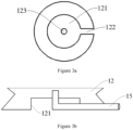
- Figure 3a is a schematic diagram of the bottom structure of the bellow pipe shown in Figure 1 .
- Figure 3b is a longitudinal sectional view of part B shown in Figure 1 .
- the bottom of the bellow pipe 12 has a bottom groove 121 and a bottom channel 122 communicating with the bottom groove 121, and a through hole 123 is disposed in the middle of the bottom groove 121.
- the cleaning liquid inlet pipe 15 is an L-shaped pipe.
- the vertical pipe of the cleaning liquid inlet pipe 15 penetrates the through hole 123 to communicate with the inside of the bellow pipe 12.
- the parallel pipe of the cleaning liquid inlet pipe 15 is embedded in the bottom channel 122 and extends to the outside of the bellow pipe 12 to facilitate the horizontal placement of the bioreactor 1.
- the bottom of the container has a concave arc-shaped bottom to facilitate placement of the carrier.
- the carrier is loaded with hepatic cells.
- the gas-liquid channel is a plurality of arc-shaped hollow structures with the same structure, and the plurality of arc-shaped hollow structures are radially evenly distributed around the junction of the liquid outlet portion and the bottom of the container body. It is conducive to the formation of turbulence after the plasma to be replaced passes through the arc-shaped hollow structure. On the one hand, it avoids the problem of the destruction of the hepatic cells caused by the shearing force of the carrier, and on the other hand, it is beneficial to drive the carrier floats slightly, so that the plasma to be replaced and the hepatic cells undergo sufficient liquid phase material exchange.
- Figure 4 is a schematic diagram of the bottom structure of the container body shown in Figure 1 .
- the center of the concave arc-shaped bottom 112 is provided with an engaging through hole 1122 to be fixedly connected with the vertical pipe of the liquid outlet 14.
- the surface of the concave arc-shaped bottom 112 is provided with four arc-shaped hollow structures 1121 with the same structure around the joint through hole 1122, and the four arc-shaped hollow structures 1121 are evenly distributed in a radial pattern, so that the container body 11 and a gas-liquid channel is formed between the bellow pipe 12.
- the open end of the container body and the cover are detachably and fixedly connected in a threaded coupled manner, and the upper end surface of the cover is not higher than the upper end surface of the container body.
- the open end of the container body has a groove, and a locking structure is provided in the middle of the groove, and the locking structure is detachably fixedly connected with the lid in a threaded coupled manner.
- the locking structure is a locking interface.
- Figure 5 is a longitudinal sectional view of the columnar structure shown in Figure 1 .
- the columnar structure 111 is a hollow cylinder with an end opening, and a locking interface 1111 is provided at the bottom of the columnar structure 111.
- the locking interface 1111 is a hollow structure with two end openings and one end penetrates the bottom of the cylindrical structure 111 to communicate with the inside of the container body 11.
- the outer sidewall of the locking interface 1111 has an external thread 1112, which is detachably and fixedly connected with the cover body (not shown in the figure) by threaded coupled.
- the bacteria-retaining sealing breathable structure includes a bacteria-retaining breathable membrane
- the top of the cover is provided with an air-permeable structure
- the bacteria-retaining breathable membrane and the bacteria-retaining sealing breathable structure make the internal and external air pressures are consistent during the using process of the bioreactor.
- the average pore diameter of the bacteria-retaining breathable membrane is less than 0.22 micron to allow gas to pass freely and block microorganisms in the air.
- a venting fixing frame is provided inside the cover to fix the bacteria-retaining breathable membrane.
- the venting fixing frame is a hollow gasket.
- a sealing gasket is further provided inside the cover to enhance the sealing performance between the cover and the container body.
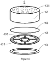
- Figure 6 is a schematic diagram of an exploded structure of the first cover according to some embodiments of the present invention.
- the first cover 6 has a first outer cover 61, a bacteria-retaining breathable membrane 62, a hollow gasket 63 and a sealing gasket 64.
- the first outer cover 61 is a hollow cylinder with an lower end opening, and the upper end surface of the first outer cover 61 is provided with 9 air-permeable through holes 611 with the same structure.
- the bacteria-retaining breathable membrane 62 is fixed inside the first outer cover 61 through the hollow gasket 63.
- the hollow gasket 63 has a circular hollow hole 632 in the middle. The surface of the hollow gasket 63 is centered on the circular hollow hole 632.
- the hollow gasket 63 is fixedly connected with the internal thread (not shown in the figure) of the inner sidewall of the first outer cover 61 by means of clamping.
- the external thread 1112 is utilized to detachably fixedly connect to the internal thread on the inner sidewall of the first outer cover 61 in a threaded coupled manner.
- the sealing gasket 64 is arranged to the lower end surface of the hollow gasket 63 to enhance the sealing performance between the first cover 6 and the cylindrical structure 111.
- the upper end surface of the first cover 6 is not higher than the upper end surface of the cylindrical structure 111 to help protect the first cover 6 and facilitate the stacking of the bioreactor 1 during transportation.
- the container body is sealed by a sealing cover. Remove the sealing cover before use and replace it with the cover.
- the bacteria-retaining sealing breathable structure further has a barrier for sealing the open end of the container body so that the inside of the bioreactor is not contaminated before use.
- a positioning adjusting member is provided inside the cover, the positioning adjusting member is provided between the bacteria-retaining breathable membrane and the barrier, and the rotation of the cover drives the positioning adjusting member moves toward the barrier to destroy the sealing performance of the barrier, so that the internal and external air pressures of the bioreactor are consistent during use.
- the cover further has a spacing member, so that the lower end surface of the blade is located above the barrier.
- the spacing member is a tear ring
- the barrier is a waterproof and breathable membrane
- Figure 7a is a schematic structural diagram of a second cover according to some embodiments of the present invention.
- Figure 7b is a schematic diagram of the exploded structure of the second cover shown in Figure 7a after the tear ring is removed.
- Figure 7c is a schematic structural diagram of the positioning cover shown in Figure 7a .
- the second cover 7 has an upper cover 71, a lower cover 72 and a tear ring 73.
- the inside of the second cover 7 is provided with the bacteria-retaining breathable membrane 62 and a positioning adjustment member (not shown in the figure).
- the positioning adjusting member (not shown in the figure) has a positioning cover 74 and a blade 741.
- the upper cover 71 is a hollow irregular cylinder with an open lower end, and the upper end surface has 14 air-permeable through holes 611.
- the antibacterial and bacteria-retaining breathable membrane 62 is fixed to the bottom of the upper cover 71 through the inner cover 74.
- the outer sidewall of the positioning cover 74 is fixedly connected to the inner sidewall of the upper cover 71.
- a fixing frame 742 is provided on the upper end surface of the positioning cover 74, and a rotating member 743 is provided inside.
- the upper end surface of the blade 741 is fixed to the lower end surface of the fixing frame 742.
- the side surface of the blade 741 is fixed on the inner sidewall of the rotating member 743, and part of the lower end surface is lower than the lower end surface of the positioning cover 74, in order to destroy the barrier (not shown in the figure) and fix the partially detached barrier (not shown in the figure) during the movement of the positioning cover 74 toward the barrier (not shown in the figure) and make sure that the internal and external air pressures of the bioreactor are consistent during use.
- the lower cover 72 is sleeved and fixed on the outside of the locking interface 1111, the lower cover 72 has an internal thread (not shown in the figure), a part of the internal thread (not shown in the figure) is fixedly connected with the external thread of the locking interface 1111 by threaded coupled, and the other part is screwed with the external thread of the outer sidewall of the rotating member 743, so that the lower end surface of the rotating member 743 reaches the first position 51, and the waterproof and breathable membrane (not shown in the figure) is located under the blade 741.
- the rotating member 743 drives the blade 741 to move toward the waterproof and breathable membrane (not shown in the figure) to reach the second position 52 and cut the waterproof and breathable membrane (not shown in the figure), makes the internal and external air pressures of the bioreactor consistent.
- the embodiment of the present invention also provides a biological reaction system, which has the bioreactor, a liquid supply unit, a liquid drain unit, a power drive unit, and a control unit.
- the liquid supply unit is fixedly connected to the liquid inlet portion and the cleaning liquid inlet portion, so as to deliver the replacement liquid to the liquid inlet portion and to deliver the cleaning liquid to the cleaning liquid inlet portion.
- the liquid drain unit is fixedly connected to the liquid outlet portion to discharge the replaced liquid or the cleaned liquid from the bioreactor; the power drive unit is used to drive the drive portion to move up and down; the control unit is used for rate control and time control of the lifting movement, and rate control and time control of the liquid supply unit and the drain unit.
- the embodiment of the present invention also provides an operating method of the bioreactor, referring to Figure 8 , comprising:
- the step S 1 further includes: destroying the spacing member, and driving the positioning adjustment member to move toward the barrier through the rotation of the cover, so as to damage the sealing performance of the barrier the inside of the bioreactor, makes the internal and external air pressure of the bioreactor consistent.
- the power driving device is a lifting platform
- the bioreactor is placed on the surface of the lifting platform, and is fixedly connected to the lifting platform through the threaded fasteners.
- the control unit is electrically connected to the lifting platform, and controls the movement speed of the lifting platform to be 5 mm/s, and the rinsing time to be 5 minutes.
- the moving speed of the lifting platform is 0.5 mm/s, and the rinsing time is 10 minutes.
- control unit controls the flow rate of the cleaning liquid from the liquid supply unit to be 0.5-5 mm/s.
- the inflow rate of the liquid to be replaced controlled by the control unit is 0.5-5 mm/s.
- the speed of the lifting movement is 0.5-5 mm/s
- the time of the gas phase material exchange is 5-120 s in each lifting cycle
- the liquid phase material exchange time is 60-400s.
- the gas phase material exchange time is the time when the carrier is above the liquid level of the replacement liquid
- the liquid phase material exchange time is the time when the carrier is below the liquid level of the replacement liquid.
Landscapes
- Health & Medical Sciences (AREA)
- Heart & Thoracic Surgery (AREA)
- Biomedical Technology (AREA)
- Engineering & Computer Science (AREA)
- Life Sciences & Earth Sciences (AREA)
- Vascular Medicine (AREA)
- Urology & Nephrology (AREA)
- Animal Behavior & Ethology (AREA)
- Veterinary Medicine (AREA)
- Anesthesiology (AREA)
- Hematology (AREA)
- General Health & Medical Sciences (AREA)
- Public Health (AREA)
- Cell Biology (AREA)
- Molecular Biology (AREA)
- Emergency Medicine (AREA)
- Zoology (AREA)
- Chemical & Material Sciences (AREA)
- Chemical Kinetics & Catalysis (AREA)
- General Chemical & Material Sciences (AREA)
- Cardiology (AREA)
- Biodiversity & Conservation Biology (AREA)
- Apparatus Associated With Microorganisms And Enzymes (AREA)
Claims (16)
- Bioreaktor (1) für ein System zur Behandlung einer bioartifiziellen Leber, umfassend:eine Abdeckung (6, 7), einen Behälterkörper (11), einen Dichtungsabschnitt (16), einen Antriebsabschnitt und einen Flüssigkeitsführungsabschnitt, wobei der Flüssigkeitsführungsabschnitt mindestens einen Flüssigkeitseinlassabschnitt und einen Flüssigkeitsauslassabschnitt aufweist; wobeiein Abdeckungskörper abnehmbar und fest mit dem Behälterkörper (11) verbunden ist und der Abdeckungskörper mit einer Belüftungsstruktur und einer bakterienrückhaltenden, abdichtenden, atmungsaktiven Struktur versehen ist, um den inneren und äußeren Luftdruck des Bioreaktors (1) konsistent zu machen;der Flüssigkeitseinlass konfiguriert ist, um die zu ersetzende Flüssigkeit in den Behälterkörper (11) zu liefern;der Flüssigkeitsauslassabschnitt die Seitenwand und die Unterseite des Behälterkörpers (11) durchdringt, um die Ersatzflüssigkeit oder die gereinigte Flüssigkeit aus dem Bioreaktor (1) abzuführen;ein Gas-Flüssigkeits-Kanal an der Unterseite des Behälterkörpers (11) angeordnet ist; undder Dichtungsabschnitt (16) entlang der äußeren Seitenwand des Bioreaktors (1) angeordnet ist, unddadurch gekennzeichnet, dassder Flüssigkeitseinlass die Seitenwand des Behälterkörpers (11) durchdringt,der Bioreaktor ferner einen Reinigungsflüssigkeitseinlassabschnitt umfasst, der ein Reinigungsflüssigkeitseinlassrohr (15) enthält, das die Unterseite des Antriebsabschnitts durchdringt, um mit dem Inneren des Antriebsabschnitts in Verbindung zu stehen, um Reinigungsflüssigkeit in den Antriebsabschnitt zu liefern;der Antriebsabschnitt dazu verwendet wird, um die Ersatzflüssigkeit oder die Reinigungsflüssigkeit anzutreiben, sich durch elastische Verformung auf und ab zu bewegen; undder Dichtungsabschnitt (16) dazu verwendet wird, den Behälterkörper (11) und den Antriebsabschnitt fest zu verbinden, um zu verhindern, dass die Flüssigkeit aus der Seitenwand des Bioreaktors (1) herausfließt, undwobei die Reinigungsflüssigkeit eine physiologische Kochsalzlösung ist und die zu ersetzende Flüssigkeit oder die Ersatzflüssigkeit Plasma ist.
- Bioreaktor (1) nach Anspruch 1, dadurch gekennzeichnet, dass der Gas-Flüssigkeits-Kanal eine Vielzahl von bogenförmigen Hohlstrukturen (1121) mit der gleichen Struktur ist, und die Vielzahl von bogenförmigen Hohlstrukturen (1121) den Flüssigkeitsauslassabschnitt umgeben und gleichmäßig in einem radialen Muster mit der Verbindung der Unterseite des Behälterkörpers (11) verteilt sind.
- Bioreaktor (1) nach Anspruch 1, dadurch gekennzeichnet, dass der Antriebsabschnitt eine Faltenbalg-Rohrstruktur mit einem offenen Ende ist.
- Bioreaktor (1) nach Anspruch 1, dadurch gekennzeichnet, dass der Behälterkörper (11) und die Abdeckung (6, 7) durch Verschraubung abnehmbar und fest verbunden sind.
- Bioreaktor (1) nach Anspruch 1, dadurch gekennzeichnet, dass die Belüftungsstruktur auf der Oberseite der Abdeckung (6, 7) angeordnet ist, die bakterienrückhaltende, abdichtende, atmungsaktive Struktur eine bakterienrückhaltende, atmungsaktive Membran (62) umfasst, und die bakterienrückhaltende, atmungsaktive Membran (62) auf der unteren Endfläche der Oberseite der Abdeckung (6, 7) angeordnet ist und eine durchschnittliche Porengröße von weniger als 0,22 Mikrometer aufweist, um Gas ungehindert passieren zu lassen, so dass der innere und äußere Luftdruck des Bioreaktors (1) konsistent ist, um Mikroorganismen in der Luft während der Verwendung zu blockieren.
- Bioreaktor (1) nach Anspruch 5, dadurch gekennzeichnet, dass die bakterienrückhaltende, abdichtende, atmungsaktive Struktur ferner eine Barriere aufweist, um das offene Ende des Behälterkörpers (11) abzudichten, so dass das Innere des Bioreaktors (1) vor der Verwendung nicht kontaminiert wird.
- Bioreaktor (1) nach Anspruch 6, dadurch gekennzeichnet, dass ferner ein Positionierungseinstellelement enthaltend im Inneren der Abdeckung (6, 7) angeordnet ist, wobei das Positionierungseinstellelement zwischen der bakterienrückhaltenden, atmungsaktiven Membran (62) und der Barriere angeordnet ist und die Drehbewegung des Abdeckungskörpers das Positionierungseinstellelement dazu antreibt, sich in Richtung der Barriere zu bewegen, um das Abdichtverhalten der Barriere zu zerstören und den inneren und äußeren Luftdruck des Bioreaktors (1) während der Verwendung konsistent zu machen.
- Bioreaktor (1) nach Anspruch 7, dadurch gekennzeichnet, dass die Barriere eine wasserdichte und atmungsaktive Membran ist.
- Bioreaktor (1) nach Anspruch 7, dadurch gekennzeichnet, dass das Positionierungseinstellelement eine Positionierungsabdeckung (74) und eine Klinge (741) aufweist, und die Klinge (741) fest mit der inneren Seitenwand der Positionierungsabdeckung (74) verbunden ist, und die äußere Seitenwand der Positionierungsabdeckung (74) mit der inneren Seitenwand der Abdeckung (6, 7) verbunden und abnehmbar fest verbunden ist, und zumindest ein Teil der unteren Endfläche der Klinge (741) niedriger als die untere Endfläche der Positionierungsabdeckung (74) ist, um die Barriere zu zerstören und zu befestigen, wenn sich die Positionierungsabdeckung (74) in Richtung der Barriere bewegt, wodurch sichergestellt wird, dass der innere und äußere Luftdruck des Bioreaktors (1) während der Verwendung konsistent sind.
- Bioreaktor (1) nach Anspruch 9, dadurch gekennzeichnet, dass die Abdeckung (6, 7) ferner ein Abstandselement aufweist, so dass sich die untere Endfläche der Klinge (741) oberhalb der Barriere befindet.
- Bioreaktor (1) nach Anspruch 10, dadurch gekennzeichnet, dass das Abstandselement ein Aufreißring (73) ist, der Aufreißring (73) die Abdeckung (6, 7) in eine obere Abdeckung (71) und eine untere Abdeckung (72) unterteilt, und die obere Abdeckung (71) durch die Positionierungsabdeckung (74) hindurchgeht und fest mit der unteren Abdeckung (72) verbunden ist, und die Oberseite der oberen Abdeckung (71) mit der luftdurchlässigen Struktur versehen ist.
- Bioreaktor (1) nach Anspruch 5, dadurch gekennzeichnet, dass er ferner einen Entlüftungsbefestigungsrahmen umfasst, der innerhalb der Abdeckung (6, 7) angeordnet ist, und dass der Entlüftungsbefestigungsrahmen die bakterienrückhaltende, atmungsaktive Membran (62) in der Abdeckung (6, 7) abnehmbar befestigt.
- Bioreaktor (1) nach Anspruch 12, dadurch gekennzeichnet, dass er ferner eine Dichtscheibe(64) umfasst, die im Inneren der Abdeckung (6, 7) angeordnet ist, und dass die Dichtscheibe (64) an der unteren Endfläche des Entlüftungsbefestigungsrahmens angeordnet ist, um den Abdeckungskörper und das Abdichtverhalten zwischen dem Behälterkörper (11) zu verstärken.
- Bioreaktor (1) nach Anspruch 1, dadurch gekennzeichnet, dass er ferner einen elastischen, wasserdichten Ring umfasst, der zwischen der inneren Seitenwand des Dichtungsabschnitts (16), der äußeren Seitenwand des Behälterkörpers (11) und der äußeren Seitenwand des Antriebsabschnitts angeordnet ist.
- Bioreaktor (1) nach Anspruch 1, dadurch gekennzeichnet, dass er ferner mindestens ein mit Gewinde versehenes Befestigungselement (162) umfasst, das an der inneren Seitenwand des Dichtungsabschnitts (16) angeordnet ist, um die Befestigung des Bioreaktors (1) zu erleichtern.
- Biologisches Reaktionssystem, umfassend:eine Flüssigkeitszuführeinheit, eine Flüssigkeitsabführeinheit, eine Leistungsantriebseinheit, eine Steuereinheit und den Bioreaktor (1) nach einem der Ansprüche 1-15, dadurch gekennzeichnet, dassdie Flüssigkeitszuführeinheit fest mit dem Flüssigkeitseinlassabschnitt und dem Reinigungsflüssigkeitseinlassrohr (15) des Bioreaktors (1) verbunden ist, um die Ersatzflüssigkeit an den Flüssigkeitseinlassabschnitt und die Reinigungsflüssigkeit an das Reinigungsflüssigkeitseinlassrohr (15) zu liefern;die Flüssigkeitsabführeinheit fest mit dem Flüssigkeitsauslassabschnitt des Bioreaktors (1) verbunden ist, um die ersetzte Flüssigkeit oder die gereinigte Flüssigkeit aus dem Bioreaktor (1) abzuführen;die Leistungsantriebseinheit dazu verwendet wird, den Antriebsabschnitt des Bioreaktors (1) anzutreiben, um eine Hubbewegung durchzuführen, unddie Steuereinheit dazu verwendet wird, um eine Ratensteuerung und eine Zeitsteuerung für die Hubbewegung durchzuführen und eine Ratensteuerung und eine Zeitsteuerung für die Flüssigkeitszuführeinheit und die Flüssigkeitsabführeinheit durchzuführen.
Applications Claiming Priority (2)
| Application Number | Priority Date | Filing Date | Title |
|---|---|---|---|
| CN201910436368.5A CN109966579B (zh) | 2019-05-24 | 2019-05-24 | 生物反应装置及生物反应系统 |
| PCT/CN2019/099681 WO2020237832A1 (zh) | 2019-05-24 | 2019-08-07 | 生物反应装置及生物反应系统 |
Publications (3)
| Publication Number | Publication Date |
|---|---|
| EP3978045A1 EP3978045A1 (de) | 2022-04-06 |
| EP3978045A4 EP3978045A4 (de) | 2022-07-06 |
| EP3978045B1 true EP3978045B1 (de) | 2023-03-29 |
Family
ID=67073898
Family Applications (1)
| Application Number | Title | Priority Date | Filing Date |
|---|---|---|---|
| EP19930183.9A Active EP3978045B1 (de) | 2019-05-24 | 2019-08-07 | Bioreaktionsvorrichtung und bioreaktionssystem |
Country Status (4)
| Country | Link |
|---|---|
| US (1) | US12102743B2 (de) |
| EP (1) | EP3978045B1 (de) |
| CN (1) | CN109966579B (de) |
| WO (1) | WO2020237832A1 (de) |
Families Citing this family (2)
| Publication number | Priority date | Publication date | Assignee | Title |
|---|---|---|---|---|
| CN109966579B (zh) * | 2019-05-24 | 2019-08-23 | 上海赛立维生物科技有限公司 | 生物反应装置及生物反应系统 |
| CN115715995B (zh) * | 2022-10-31 | 2025-11-18 | 浙江赛宁生物科技有限公司 | 一种流式管及其使用方法 |
Family Cites Families (21)
| Publication number | Priority date | Publication date | Assignee | Title |
|---|---|---|---|---|
| US5202262A (en) * | 1984-01-31 | 1993-04-13 | Millipore Corporation | Apparatus for microbiological testing of liquids |
| JPH0564576A (ja) * | 1991-09-06 | 1993-03-19 | Tabai Espec Corp | カラム型培養装置 |
| CN1260343C (zh) * | 2002-01-31 | 2006-06-21 | 赛宇细胞科技股份有限公司 | 细胞培养装置 |
| ES2733318T3 (es) * | 2004-05-06 | 2019-11-28 | Univ Hospital Of Basel | Biorreactor para ingeniería de tejidos |
| AU2008209309B2 (en) * | 2007-01-22 | 2012-06-07 | Ian Malcolm Wright | A variable volume bioreactor |
| CN100544684C (zh) * | 2007-08-13 | 2009-09-30 | 浙江大学 | 人工肝用微囊悬浮型流化床式生物反应器 |
| CN201140851Y (zh) * | 2008-01-18 | 2008-10-29 | 张政 | 一种自带割口刀片式塑料瓶盖 |
| CN101368156B (zh) * | 2008-09-28 | 2011-02-09 | 陕西科技大学 | 一种脉动生物反应器中的差压调节器 |
| DE102011107400B3 (de) | 2011-07-07 | 2012-10-04 | Hugo Sachs Elektronik - Harvard Apparatus GmbH | Bioreaktor |
| US20150064780A1 (en) * | 2012-04-02 | 2015-03-05 | The Children's Mercy Hospital | Disposable single use self-contained cyclic pressure and flow bioreactor system |
| CN202642396U (zh) * | 2012-06-26 | 2013-01-02 | 四川斯比泰饮料食品有限公司 | 一种双瓶盖结构 |
| CN202704166U (zh) * | 2012-07-17 | 2013-01-30 | 傅敏 | 一种料水分离的瓶盖组件 |
| CN104353142B (zh) * | 2014-09-30 | 2017-01-11 | 南京比瑞生物科技有限公司 | 一种生物人工肝反应器 |
| CN204399768U (zh) * | 2015-01-05 | 2015-06-17 | 郑永通 | 一种推注式加料瓶盖 |
| CN204399717U (zh) * | 2015-01-05 | 2015-06-17 | 郑永通 | 推注式加料瓶盖 |
| CN105457115B (zh) * | 2015-11-23 | 2018-03-13 | 南方医科大学珠江医院 | 混合型生物人工肝系统的连接方法 |
| CN205256967U (zh) * | 2015-12-21 | 2016-05-25 | 翟正 | 固液分离型瓶盖 |
| US10570043B2 (en) * | 2016-08-31 | 2020-02-25 | Conly L. Hansen | Induced sludge bed anaerobic reactor system |
| CN207445274U (zh) | 2017-01-23 | 2018-06-05 | 上海赛立维生物科技有限公司 | 一种人工肝反应器及循环灌注式生物人工肝支持系统 |
| CN106620916A (zh) | 2017-01-23 | 2017-05-10 | 上海赛立维生物科技有限公司 | 一种人工肝反应器及其制备方法和应用 |
| CN109966579B (zh) * | 2019-05-24 | 2019-08-23 | 上海赛立维生物科技有限公司 | 生物反应装置及生物反应系统 |
-
2019
- 2019-05-24 CN CN201910436368.5A patent/CN109966579B/zh active Active
- 2019-08-07 US US17/614,328 patent/US12102743B2/en active Active
- 2019-08-07 WO PCT/CN2019/099681 patent/WO2020237832A1/zh not_active Ceased
- 2019-08-07 EP EP19930183.9A patent/EP3978045B1/de active Active
Also Published As
| Publication number | Publication date |
|---|---|
| EP3978045A1 (de) | 2022-04-06 |
| WO2020237832A1 (zh) | 2020-12-03 |
| CN109966579A (zh) | 2019-07-05 |
| US12102743B2 (en) | 2024-10-01 |
| EP3978045A4 (de) | 2022-07-06 |
| US20220218887A1 (en) | 2022-07-14 |
| CN109966579B (zh) | 2019-08-23 |
Similar Documents
| Publication | Publication Date | Title |
|---|---|---|
| EP3978045B1 (de) | Bioreaktionsvorrichtung und bioreaktionssystem | |
| CN101732771B (zh) | 一种细胞反应器及包括该反应器的人工肝支持系统 | |
| US20170037357A1 (en) | Automated cell culturing and harvesting device | |
| CN108455726B (zh) | 一种双循环式厌氧反应器 | |
| PT585419E (pt) | Processo e aparelho para a cultura de particulas de biomassa | |
| CN103877631A (zh) | 生物人工肝系统 | |
| CN103170021A (zh) | 人工肝用导流式微囊悬浮型流化床式生物反应器 | |
| US11400199B2 (en) | Bioartificial liver based on human iPSCs-derived hepatocyte-like cells and multilayer porous bioreactor | |
| CN102091360B (zh) | 生物人工肝用往返翻转灌流型生物反应器及其处理方法 | |
| CN101711898B (zh) | 人工肝用微囊悬浮型搅拌池式生物反应器 | |
| CN106620916A (zh) | 一种人工肝反应器及其制备方法和应用 | |
| CN115895887B (zh) | 流感疫苗的生产装置、方法及流感疫苗 | |
| CN201999942U (zh) | 生物反应容器及生物人工肝用往返翻转灌流型生物反应器 | |
| CN204714806U (zh) | 一种体外肝灌流装置 | |
| KR101263820B1 (ko) | 재생성 세포 추출장치 | |
| CN101569767B (zh) | 配备多孔砖式填充支架型反应器的混合型人工肝支持系统 | |
| US12241050B2 (en) | Perfusion filter assembly for increased cross flow | |
| WO2024183294A1 (zh) | 细胞处理设备及细胞处理方法 | |
| CN102210892B (zh) | 一种集成式微囊悬浮型流化床式生物反应器 | |
| CN204766767U (zh) | 全血灌流生物人工肝系统 | |
| CN209933696U (zh) | 一种用于泵用输液器的止流装置 | |
| CN223329327U (zh) | 一种用于巨噬细胞共培养的多腔体细胞培养装置 | |
| CN207897623U (zh) | 一种潮汐式植物组织培养生物反应器及系统培养装置 | |
| CN109971634B (zh) | 生物人工肝反应器及其操作方法 | |
| CN113462531A (zh) | 一种生物组织处理系统 |
Legal Events
| Date | Code | Title | Description |
|---|---|---|---|
| STAA | Information on the status of an ep patent application or granted ep patent |
Free format text: STATUS: UNKNOWN |
|
| STAA | Information on the status of an ep patent application or granted ep patent |
Free format text: STATUS: THE INTERNATIONAL PUBLICATION HAS BEEN MADE |
|
| PUAI | Public reference made under article 153(3) epc to a published international application that has entered the european phase |
Free format text: ORIGINAL CODE: 0009012 |
|
| STAA | Information on the status of an ep patent application or granted ep patent |
Free format text: STATUS: REQUEST FOR EXAMINATION WAS MADE |
|
| 17P | Request for examination filed |
Effective date: 20211220 |
|
| AK | Designated contracting states |
Kind code of ref document: A1 Designated state(s): AL AT BE BG CH CY CZ DE DK EE ES FI FR GB GR HR HU IE IS IT LI LT LU LV MC MK MT NL NO PL PT RO RS SE SI SK SM TR |
|
| A4 | Supplementary search report drawn up and despatched |
Effective date: 20220608 |
|
| RIC1 | Information provided on ipc code assigned before grant |
Ipc: A61M 1/36 20060101ALI20220601BHEP Ipc: A61F 2/00 20060101ALI20220601BHEP Ipc: A61M 1/34 20060101ALI20220601BHEP Ipc: C12N 7/00 20060101ALI20220601BHEP Ipc: A61M 1/16 20060101AFI20220601BHEP |
|
| DAV | Request for validation of the european patent (deleted) | ||
| DAX | Request for extension of the european patent (deleted) | ||
| GRAP | Despatch of communication of intention to grant a patent |
Free format text: ORIGINAL CODE: EPIDOSNIGR1 |
|
| STAA | Information on the status of an ep patent application or granted ep patent |
Free format text: STATUS: GRANT OF PATENT IS INTENDED |
|
| INTG | Intention to grant announced |
Effective date: 20221103 |
|
| GRAS | Grant fee paid |
Free format text: ORIGINAL CODE: EPIDOSNIGR3 |
|
| GRAA | (expected) grant |
Free format text: ORIGINAL CODE: 0009210 |
|
| STAA | Information on the status of an ep patent application or granted ep patent |
Free format text: STATUS: THE PATENT HAS BEEN GRANTED |
|
| AK | Designated contracting states |
Kind code of ref document: B1 Designated state(s): AL AT BE BG CH CY CZ DE DK EE ES FI FR GB GR HR HU IE IS IT LI LT LU LV MC MK MT NL NO PL PT RO RS SE SI SK SM TR |
|
| REG | Reference to a national code |
Ref country code: CH Ref legal event code: EP |
|
| REG | Reference to a national code |
Ref country code: DE Ref legal event code: R096 Ref document number: 602019027054 Country of ref document: DE |
|
| REG | Reference to a national code |
Ref country code: AT Ref legal event code: REF Ref document number: 1556231 Country of ref document: AT Kind code of ref document: T Effective date: 20230415 |
|
| REG | Reference to a national code |
Ref country code: IE Ref legal event code: FG4D |
|
| REG | Reference to a national code |
Ref country code: LT Ref legal event code: MG9D |
|
| PG25 | Lapsed in a contracting state [announced via postgrant information from national office to epo] |
Ref country code: RS Free format text: LAPSE BECAUSE OF FAILURE TO SUBMIT A TRANSLATION OF THE DESCRIPTION OR TO PAY THE FEE WITHIN THE PRESCRIBED TIME-LIMIT Effective date: 20230329 Ref country code: NO Free format text: LAPSE BECAUSE OF FAILURE TO SUBMIT A TRANSLATION OF THE DESCRIPTION OR TO PAY THE FEE WITHIN THE PRESCRIBED TIME-LIMIT Effective date: 20230629 Ref country code: LV Free format text: LAPSE BECAUSE OF FAILURE TO SUBMIT A TRANSLATION OF THE DESCRIPTION OR TO PAY THE FEE WITHIN THE PRESCRIBED TIME-LIMIT Effective date: 20230329 Ref country code: LT Free format text: LAPSE BECAUSE OF FAILURE TO SUBMIT A TRANSLATION OF THE DESCRIPTION OR TO PAY THE FEE WITHIN THE PRESCRIBED TIME-LIMIT Effective date: 20230329 Ref country code: HR Free format text: LAPSE BECAUSE OF FAILURE TO SUBMIT A TRANSLATION OF THE DESCRIPTION OR TO PAY THE FEE WITHIN THE PRESCRIBED TIME-LIMIT Effective date: 20230329 |
|
| REG | Reference to a national code |
Ref country code: NL Ref legal event code: MP Effective date: 20230329 |
|
| REG | Reference to a national code |
Ref country code: AT Ref legal event code: MK05 Ref document number: 1556231 Country of ref document: AT Kind code of ref document: T Effective date: 20230329 |
|
| PG25 | Lapsed in a contracting state [announced via postgrant information from national office to epo] |
Ref country code: SE Free format text: LAPSE BECAUSE OF FAILURE TO SUBMIT A TRANSLATION OF THE DESCRIPTION OR TO PAY THE FEE WITHIN THE PRESCRIBED TIME-LIMIT Effective date: 20230329 Ref country code: NL Free format text: LAPSE BECAUSE OF FAILURE TO SUBMIT A TRANSLATION OF THE DESCRIPTION OR TO PAY THE FEE WITHIN THE PRESCRIBED TIME-LIMIT Effective date: 20230329 Ref country code: GR Free format text: LAPSE BECAUSE OF FAILURE TO SUBMIT A TRANSLATION OF THE DESCRIPTION OR TO PAY THE FEE WITHIN THE PRESCRIBED TIME-LIMIT Effective date: 20230630 Ref country code: FI Free format text: LAPSE BECAUSE OF FAILURE TO SUBMIT A TRANSLATION OF THE DESCRIPTION OR TO PAY THE FEE WITHIN THE PRESCRIBED TIME-LIMIT Effective date: 20230329 |
|
| PG25 | Lapsed in a contracting state [announced via postgrant information from national office to epo] |
Ref country code: SM Free format text: LAPSE BECAUSE OF FAILURE TO SUBMIT A TRANSLATION OF THE DESCRIPTION OR TO PAY THE FEE WITHIN THE PRESCRIBED TIME-LIMIT Effective date: 20230329 Ref country code: RO Free format text: LAPSE BECAUSE OF FAILURE TO SUBMIT A TRANSLATION OF THE DESCRIPTION OR TO PAY THE FEE WITHIN THE PRESCRIBED TIME-LIMIT Effective date: 20230329 Ref country code: PT Free format text: LAPSE BECAUSE OF FAILURE TO SUBMIT A TRANSLATION OF THE DESCRIPTION OR TO PAY THE FEE WITHIN THE PRESCRIBED TIME-LIMIT Effective date: 20230731 Ref country code: ES Free format text: LAPSE BECAUSE OF FAILURE TO SUBMIT A TRANSLATION OF THE DESCRIPTION OR TO PAY THE FEE WITHIN THE PRESCRIBED TIME-LIMIT Effective date: 20230329 Ref country code: EE Free format text: LAPSE BECAUSE OF FAILURE TO SUBMIT A TRANSLATION OF THE DESCRIPTION OR TO PAY THE FEE WITHIN THE PRESCRIBED TIME-LIMIT Effective date: 20230329 Ref country code: AT Free format text: LAPSE BECAUSE OF FAILURE TO SUBMIT A TRANSLATION OF THE DESCRIPTION OR TO PAY THE FEE WITHIN THE PRESCRIBED TIME-LIMIT Effective date: 20230329 |
|
| PG25 | Lapsed in a contracting state [announced via postgrant information from national office to epo] |
Ref country code: SK Free format text: LAPSE BECAUSE OF FAILURE TO SUBMIT A TRANSLATION OF THE DESCRIPTION OR TO PAY THE FEE WITHIN THE PRESCRIBED TIME-LIMIT Effective date: 20230329 Ref country code: PL Free format text: LAPSE BECAUSE OF FAILURE TO SUBMIT A TRANSLATION OF THE DESCRIPTION OR TO PAY THE FEE WITHIN THE PRESCRIBED TIME-LIMIT Effective date: 20230329 Ref country code: IS Free format text: LAPSE BECAUSE OF FAILURE TO SUBMIT A TRANSLATION OF THE DESCRIPTION OR TO PAY THE FEE WITHIN THE PRESCRIBED TIME-LIMIT Effective date: 20230729 |
|
| REG | Reference to a national code |
Ref country code: DE Ref legal event code: R097 Ref document number: 602019027054 Country of ref document: DE |
|
| PG25 | Lapsed in a contracting state [announced via postgrant information from national office to epo] |
Ref country code: DK Free format text: LAPSE BECAUSE OF FAILURE TO SUBMIT A TRANSLATION OF THE DESCRIPTION OR TO PAY THE FEE WITHIN THE PRESCRIBED TIME-LIMIT Effective date: 20230329 Ref country code: CZ Free format text: LAPSE BECAUSE OF FAILURE TO SUBMIT A TRANSLATION OF THE DESCRIPTION OR TO PAY THE FEE WITHIN THE PRESCRIBED TIME-LIMIT Effective date: 20230329 |
|
| PLBE | No opposition filed within time limit |
Free format text: ORIGINAL CODE: 0009261 |
|
| STAA | Information on the status of an ep patent application or granted ep patent |
Free format text: STATUS: NO OPPOSITION FILED WITHIN TIME LIMIT |
|
| 26N | No opposition filed |
Effective date: 20240103 |
|
| PG25 | Lapsed in a contracting state [announced via postgrant information from national office to epo] |
Ref country code: MC Free format text: LAPSE BECAUSE OF FAILURE TO SUBMIT A TRANSLATION OF THE DESCRIPTION OR TO PAY THE FEE WITHIN THE PRESCRIBED TIME-LIMIT Effective date: 20230329 |
|
| REG | Reference to a national code |
Ref country code: CH Ref legal event code: PL |
|
| PG25 | Lapsed in a contracting state [announced via postgrant information from national office to epo] |
Ref country code: MC Free format text: LAPSE BECAUSE OF FAILURE TO SUBMIT A TRANSLATION OF THE DESCRIPTION OR TO PAY THE FEE WITHIN THE PRESCRIBED TIME-LIMIT Effective date: 20230329 |
|
| PG25 | Lapsed in a contracting state [announced via postgrant information from national office to epo] |
Ref country code: LU Free format text: LAPSE BECAUSE OF NON-PAYMENT OF DUE FEES Effective date: 20230807 |
|
| PG25 | Lapsed in a contracting state [announced via postgrant information from national office to epo] |
Ref country code: LU Free format text: LAPSE BECAUSE OF NON-PAYMENT OF DUE FEES Effective date: 20230807 Ref country code: CH Free format text: LAPSE BECAUSE OF NON-PAYMENT OF DUE FEES Effective date: 20230831 |
|
| PG25 | Lapsed in a contracting state [announced via postgrant information from national office to epo] |
Ref country code: SI Free format text: LAPSE BECAUSE OF FAILURE TO SUBMIT A TRANSLATION OF THE DESCRIPTION OR TO PAY THE FEE WITHIN THE PRESCRIBED TIME-LIMIT Effective date: 20230329 |
|
| REG | Reference to a national code |
Ref country code: BE Ref legal event code: MM Effective date: 20230831 |
|
| REG | Reference to a national code |
Ref country code: IE Ref legal event code: MM4A |
|
| PG25 | Lapsed in a contracting state [announced via postgrant information from national office to epo] |
Ref country code: SI Free format text: LAPSE BECAUSE OF FAILURE TO SUBMIT A TRANSLATION OF THE DESCRIPTION OR TO PAY THE FEE WITHIN THE PRESCRIBED TIME-LIMIT Effective date: 20230329 Ref country code: IT Free format text: LAPSE BECAUSE OF FAILURE TO SUBMIT A TRANSLATION OF THE DESCRIPTION OR TO PAY THE FEE WITHIN THE PRESCRIBED TIME-LIMIT Effective date: 20230329 |
|
| PG25 | Lapsed in a contracting state [announced via postgrant information from national office to epo] |
Ref country code: IE Free format text: LAPSE BECAUSE OF NON-PAYMENT OF DUE FEES Effective date: 20230807 |
|
| PG25 | Lapsed in a contracting state [announced via postgrant information from national office to epo] |
Ref country code: IE Free format text: LAPSE BECAUSE OF NON-PAYMENT OF DUE FEES Effective date: 20230807 |
|
| PG25 | Lapsed in a contracting state [announced via postgrant information from national office to epo] |
Ref country code: BE Free format text: LAPSE BECAUSE OF NON-PAYMENT OF DUE FEES Effective date: 20230831 |
|
| PGFP | Annual fee paid to national office [announced via postgrant information from national office to epo] |
Ref country code: DE Payment date: 20240819 Year of fee payment: 6 |
|
| PGFP | Annual fee paid to national office [announced via postgrant information from national office to epo] |
Ref country code: FR Payment date: 20240815 Year of fee payment: 6 |
|
| PG25 | Lapsed in a contracting state [announced via postgrant information from national office to epo] |
Ref country code: BG Free format text: LAPSE BECAUSE OF FAILURE TO SUBMIT A TRANSLATION OF THE DESCRIPTION OR TO PAY THE FEE WITHIN THE PRESCRIBED TIME-LIMIT Effective date: 20230329 |
|
| PG25 | Lapsed in a contracting state [announced via postgrant information from national office to epo] |
Ref country code: BG Free format text: LAPSE BECAUSE OF FAILURE TO SUBMIT A TRANSLATION OF THE DESCRIPTION OR TO PAY THE FEE WITHIN THE PRESCRIBED TIME-LIMIT Effective date: 20230329 |
|
| PG25 | Lapsed in a contracting state [announced via postgrant information from national office to epo] |
Ref country code: CY Free format text: LAPSE BECAUSE OF FAILURE TO SUBMIT A TRANSLATION OF THE DESCRIPTION OR TO PAY THE FEE WITHIN THE PRESCRIBED TIME-LIMIT; INVALID AB INITIO Effective date: 20190807 |
|
| PG25 | Lapsed in a contracting state [announced via postgrant information from national office to epo] |
Ref country code: HU Free format text: LAPSE BECAUSE OF FAILURE TO SUBMIT A TRANSLATION OF THE DESCRIPTION OR TO PAY THE FEE WITHIN THE PRESCRIBED TIME-LIMIT; INVALID AB INITIO Effective date: 20190807 |
|
| PGFP | Annual fee paid to national office [announced via postgrant information from national office to epo] |
Ref country code: GB Payment date: 20250730 Year of fee payment: 7 |
|
| PG25 | Lapsed in a contracting state [announced via postgrant information from national office to epo] |
Ref country code: TR Free format text: LAPSE BECAUSE OF FAILURE TO SUBMIT A TRANSLATION OF THE DESCRIPTION OR TO PAY THE FEE WITHIN THE PRESCRIBED TIME-LIMIT Effective date: 20230329 |