EP3977786B1 - Power limits based on signal type for managing maximum permissible exposure - Google Patents
Power limits based on signal type for managing maximum permissible exposure Download PDFInfo
- Publication number
- EP3977786B1 EP3977786B1 EP20729522.1A EP20729522A EP3977786B1 EP 3977786 B1 EP3977786 B1 EP 3977786B1 EP 20729522 A EP20729522 A EP 20729522A EP 3977786 B1 EP3977786 B1 EP 3977786B1
- Authority
- EP
- European Patent Office
- Prior art keywords
- transmission power
- exposure
- signal
- type
- transmitting
- Prior art date
- Legal status (The legal status is an assumption and is not a legal conclusion. Google has not performed a legal analysis and makes no representation as to the accuracy of the status listed.)
- Active
Links
Images




Classifications
-
- H—ELECTRICITY
- H04—ELECTRIC COMMUNICATION TECHNIQUE
- H04W—WIRELESS COMMUNICATION NETWORKS
- H04W52/00—Power management, e.g. Transmission Power Control [TPC] or power classes
- H04W52/04—Transmission power control [TPC]
- H04W52/06—TPC algorithms
- H04W52/16—Deriving transmission power values from another channel
-
- H—ELECTRICITY
- H04—ELECTRIC COMMUNICATION TECHNIQUE
- H04W—WIRELESS COMMUNICATION NETWORKS
- H04W72/00—Local resource management
- H04W72/04—Wireless resource allocation
- H04W72/044—Wireless resource allocation based on the type of the allocated resource
- H04W72/0473—Wireless resource allocation based on the type of the allocated resource the resource being transmission power
-
- H—ELECTRICITY
- H04—ELECTRIC COMMUNICATION TECHNIQUE
- H04W—WIRELESS COMMUNICATION NETWORKS
- H04W52/00—Power management, e.g. Transmission Power Control [TPC] or power classes
- H04W52/04—Transmission power control [TPC]
- H04W52/18—TPC being performed according to specific parameters
- H04W52/22—TPC being performed according to specific parameters taking into account previous information or commands
- H04W52/225—Calculation of statistics, e.g. average or variance
-
- H—ELECTRICITY
- H04—ELECTRIC COMMUNICATION TECHNIQUE
- H04W—WIRELESS COMMUNICATION NETWORKS
- H04W52/00—Power management, e.g. Transmission Power Control [TPC] or power classes
- H04W52/04—Transmission power control [TPC]
- H04W52/18—TPC being performed according to specific parameters
- H04W52/28—TPC being performed according to specific parameters using user profile, e.g. mobile speed, priority or network state, e.g. standby, idle or non-transmission
- H04W52/281—TPC being performed according to specific parameters using user profile, e.g. mobile speed, priority or network state, e.g. standby, idle or non-transmission taking into account user or data type priority
-
- H—ELECTRICITY
- H04—ELECTRIC COMMUNICATION TECHNIQUE
- H04W—WIRELESS COMMUNICATION NETWORKS
- H04W52/00—Power management, e.g. Transmission Power Control [TPC] or power classes
- H04W52/04—Transmission power control [TPC]
- H04W52/30—Transmission power control [TPC] using constraints in the total amount of available transmission power
- H04W52/36—Transmission power control [TPC] using constraints in the total amount of available transmission power with a discrete range or set of values, e.g. step size, ramping or offsets
- H04W52/367—Power values between minimum and maximum limits, e.g. dynamic range
-
- H—ELECTRICITY
- H04—ELECTRIC COMMUNICATION TECHNIQUE
- H04W—WIRELESS COMMUNICATION NETWORKS
- H04W72/00—Local resource management
- H04W72/20—Control channels or signalling for resource management
- H04W72/21—Control channels or signalling for resource management in the uplink direction of a wireless link, i.e. towards the network
-
- H—ELECTRICITY
- H04—ELECTRIC COMMUNICATION TECHNIQUE
- H04W—WIRELESS COMMUNICATION NETWORKS
- H04W72/00—Local resource management
- H04W72/50—Allocation or scheduling criteria for wireless resources
- H04W72/56—Allocation or scheduling criteria for wireless resources based on priority criteria
-
- H—ELECTRICITY
- H04—ELECTRIC COMMUNICATION TECHNIQUE
- H04W—WIRELESS COMMUNICATION NETWORKS
- H04W52/00—Power management, e.g. Transmission Power Control [TPC] or power classes
- H04W52/04—Transmission power control [TPC]
- H04W52/06—TPC algorithms
- H04W52/14—Separate analysis of uplink or downlink
- H04W52/146—Uplink power control
Definitions
- EP 2378819 A2 discloses a radio communication system. More particularly, it relates to a signal transmission method in which a terminal transmits a signal in a radio communication system, said method comprising the steps of determining the transmission power for both a first channel and a second channel independently from one another; reducing at least the transmission power of the first channel or the transmission power of the second channel in consideration of a channel priority when the sum of the transmission power of the first channel and the transmission power of the second channel exceeds a maximum transmission power, and transmitting signals at the same time to a base station through the first channel and the second channel.
- EP 2739094 A1 discloses a power control method and terminal equipment.
- the method includes: dropping, by terminal equipment, an SRS signal in other serving cell(s) or puncturing symbols of a PRACH signal in a secondary serving cell within the same OFDM symbol as the SRS signal in the other serving cell(s), when the terminal equipment needs to transmit the PRACH signal in the secondary serving cell and transmit the uplink SRS signal in the other serving cell(s) within the same OFDM symbol.
- the transmission power of the terminal equipment is lowered by dropping the SRS signals and transmitting only the PRACH signals, or by puncturing the PRACH signals in the same OFDM symbol as the SRS signals and transmitting only the SRS signals.
- WO 2013/181444 A2 discloses a Device-to-device (D2D) cross link power control systems and methods.
- a device such as a UE or WTRU may determine whether it may have simultaneous transmissions where at least one of the transmissions may include a cross link transmission.
- the device may further determine whether a total transmit power of the simultaneous transmissions may exceed a maximum transmit power of the device. If the device may have simultaneous transmissions and such transmissions may exceed the maximum transmit power, the device may reallocate power based on a priority or priority setting.
- the device may further determine a maximum cross link power, a maximum device power, and a cross link transmit power level such that the device may further control the power for transmissions based thereon.
- US 2016/286497 A1 discloses a method and apparatus for executing an uplink channel power control in dual connectivity configuration when power is limited.
- An appropriate power controlling method may be determined based on a priority, and may be applied to a UE that has dual connectivity with a Master eNB (MeNB) and a Secondary eNB (SeNB) in a network.
- MeNB Master eNB
- SeNB Secondary eNB
- a wireless device may determine a first transmission power for transmitting a first type of uplink (UL) signal and a second transmission power for transmitting a second type of UL signal based on the first transmission power. Thereafter, the wireless device may transmit at least one of the first UL signal according to the first transmission power or the second UL signal according to the second transmission power.
- UL uplink
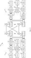
- FIG. 2 illustrates example components of BS 110a and UE 120a (e.g., in the wireless communication network 100 of FIG. 1 ), which may be used to implement aspects of the present disclosure.
- a transmit processor 220 may receive data from a data source 212 and control information from a controller/processor 240.
- the control information may be for the physical broadcast channel (PBCH), physical control format indicator channel (PCFICH), physical hybrid ARQ indicator channel (PHICH), physical downlink control channel (PDCCH), group common PDCCH (GC PDCCH), etc.
- the data may be for the physical downlink shared channel (PDSCH), etc.
- a medium access control (MAC)-control element (MAC-CE) is a MAC layer communication structure that may be used for control command exchange between wireless nodes.
- the MAC-CE may be carried in a shared channel such as a physical downlink shared channel (PDSCH), a physical uplink shared channel (PUSCH), or a physical sidelink shared channel (PSSCH).
- SAR may be used to assess RF exposure for transmission frequencies less than 6 GHz, covering wireless communication technologies such as 3G (e.g., CDMA), 4G (e.g., LTE), 5G (e.g., NR in 6 GHz bands), IEEE 802. 11ac, and the like.
- Power density may be used to assess RF exposure for transmission frequencies higher than 10 GHz, covering wireless communication technologies such as IEEE 802.11ad, 802.11ay, 5G, and the like.
- different metrics may be used to assess RF exposure for different wireless communication technologies.
- the SAR values in each SAR distribution may correspond to a particular transmission power level (e.g., the transmission power level at which the SAR values were measured in the test laboratory). Accordingly, since SAR scales with transmission power level, the processor may scale a SAR distribution for any transmission power level by multiplying each SAR value in the SAR distribution by the following transmission power scaler: Tx c Tx SAR where Tx c is a current transmission power level for the respective transmit scenario, and Tx SAR is the transmission power level corresponding to the SAR values in the stored SAR distribution (e.g., the transmission power level at which the SAR values were measured in the test laboratory).
- Tx c is a current transmission power level for the respective transmit scenario
- Tx SAR is the transmission power level corresponding to the SAR values in the stored SAR distribution (e.g., the transmission power level at which the SAR values were measured in the test laboratory).
- the wireless device may support multiple transmit scenarios for the first technology.
- the transmit scenarios may be specified by a set of parameters.
- the set of parameters may include one or more of the following: an antenna parameter indicating one or more antennas used for transmission (i.e., active antennas), a frequency band parameter indicating one or more frequency bands used for transmission (i.e., active frequency bands), a channel parameter indicating one or more channels used for transmission (i.e., active channels), a body position parameter indicating the location of the wireless device relative to the user's body location (head, trunk, away from the body, etc.), and/or other parameters.
- a SAR distribution may be normalized with respect to a SAR limit by dividing each SAR value in the SAR distribution by the SAR limit. In this case, a normalized SAR value exceeds the SAR limit when the normalized SAR value is greater than one, and is below the SAR limit when the normalized SAR value is less than one.
- each of the SAR distributions stored in the memory may be normalized with respect to a SAR limit.
- the normalized SAR distribution for a transmit scenario may be generated by combining two or more normalized SAR distributions.
- a normalized SAR distribution for a transmit scenario in which two or more antennas are active may be generated by combining the normalized SAR distributions for the two or more active antennas.
- the normalized SAR distribution for each active antenna may be scaled by the respective transmission power level before combining the normalized SAR distributions for the active antennas.
- SAR norm_i is the normalized SAR distribution for the i th active antenna.
- the PD distribution (also referred to as PD map) for each transmit scenario may be generated based on measurements (e.g., E-field measurements) performed in a test laboratory using a model of a human body. After the PD distributions are generated, the PD distributions may be stored in the memory to enable the processor (e.g., processor 266 of FIG. 2 or processor 334 of FIG. 3 ) to assess RF exposure in real time, as discussed further below.
- Each PD distribution includes a set of PD values, where each PD value may correspond to a different location (e.g., on the model of the human body).
- PD measurements may be performed for each one of multiple frequency bands to generate a PD distribution for each one of the multiple frequency bands.
- a PD distribution for a transmit scenario in which two or more frequency bands are active may be generated by combining the PD distributions for the two or more active frequency bands.
- normalized PD distributions for different frequency bands may be stored in the memory.
- a normalized PD distribution for a transmit scenario in which two or more frequency bands are active may be generated by combining the normalized PD distributions for the two or more active frequency bands.
- the normalized PD distribution for each of the active frequency bands may be scaled by the respective transmission power level before combining the normalized PD distributions for the active frequency bands.
- the combined PD distribution may also be computed using equation 6a in which i is an index for the active frequency bands, PD norm_i is the normalized PD distribution for the i th active frequency band, Tx i is the transmission power level for the i th active frequency band, and Tx PDi is the transmission power level for the normalized PD distribution for the i th active frequency band.
- MPE maximum permissible exposure
- ICNIRP International Commission on Non-Ionizing Radiation Protection
- FCC Federal Communications Commission
- the MPE limit(s) may be converted into a constraint related to the maximum transmission power by one or more devices (e.g., depending on the implementation of each of the devices) and, thus, a signal transmitted by a device may be limited due to MPE compliance.
- the shared power limits may significantly reduce an available transmission power for mission critical signals, such as a control signal.
- the UL may be significantly power limited due to MPE and an UL data signal (e.g., transmitted on a physical uplink shared channel (PUSCH)) may use up all or most of the available power limit, leaving no or very little power limit for a control signal (e.g., transmitted on a physical uplink control channel (PUCCH)), resulting in failure of the control channel.
- PUSCH physical uplink shared channel
- aspects of the present disclosure provide techniques to help alleviate this issue with power limit allocation. For example, in some cases, aspects provide techniques that allocate power limit based on a type of signal to be transmitted. More specifically, in some cases, higher priority types of signals (e.g., such as mission critical/control signals) may be allocated power before lesser priority types of signals (e.g., data signals), alleviating the possibility of channel failure associated with the higher priority signals.
- higher priority types of signals e.g., such as mission critical/control signals
- lesser priority types of signals e.g., data signals
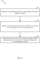
- FIG. 4 is a flow diagram illustrating example operations 400 for determining transmission power levels according to signal types and RF exposure limits, in accordance with certain aspects of the present disclosure.
- the operations 400 may be performed, for example, by a wireless device (e.g., such as a UE 120a in the wireless communication network 100).
- Operations 400 may be implemented as software components that are executed and run on one or more processors (e.g., controller/processor 280 of FIG. 2 ).
- the transmission and reception of signals by the UE in operations 400 may be enabled, for example, by one or more antennas (e.g., antennas 252 of FIG. 2 ).
- the transmission and/or reception of signals by the UE may be implemented via a bus interface of one or more processors (e.g., controller/processor 280) obtaining and/or outputting signals.
- the operations 400 may be performed by a transceiver front-end (e.g., transceiver front-end 300 of FIG. 3 ) of a wireless device, such as the processor 334, TX path 302, and interface 306 of FIG. 3 .
- a processor e.g., processor 334 of FIG. 3
- an interface e.g., interface 306
- antenna e.g., antenna 303
- the operations 400 may begin, at block 402, with the wireless device determining a first transmission power for transmitting a first type of uplink (UL) signal.
- UL uplink
- the wireless device determines a second transmission power for transmitting a second type of UL signal.
- determining the first transmission power and/or determining the second transmission power may be based on at least one of a radio frequency (RF) exposure limit or a transmission power limit for transmitting UL signals by the UE.
- the second transmission power may be determined after the first transmission power and from a remaining RF exposure (e.g., remaining from the first transmission power determination), as described in greater detail below.
- the wireless device transmits at least one of the first UL signal according to the first transmission power or the second UL signal according to the second transmission power.
- aspects of the present disclosure provide techniques for power limit allocation based on a signal type of an UL signal to be transmitted. For example, as noted above, the UE may determine a first transmission power for transmitting a first type of UL signal and determine a second transmission power for transmitting a second type of UL signal.
- the first type of UL signal may comprise a control signal and the second type of UL signal may comprise a data signal.
- the transmission power determination may be based on a priority between types of signals.
- the control signal may have a higher priority to an available transmission power for the transmitting than the data signal.
- the first transmission power determination may take priority over the second transmission power.
- the first transmission power and/or the second transmission power may be determined based on at least one of a radio frequency (RF) exposure limit (e.g., a power density (PD) limit or a specific absorption rate (SAR) limit) or a transmission power limit for transmitting UL signals by the UE.
- RF radio frequency
- determining the first transmission power may include determining a first RF exposure associated with transmitting the first type of UL signal. Thereafter, the first transmission power may be determined based on the determined first RF exposure associated with transmitting the first type of UL signal.
- determining the first transmission power based on the determined first RF exposure may include determining a maximum transmission power for the first type of UL signal that satisfies the first RF exposure over a particular period of time or time window, wherein the first transmission power comprises the maximum transmission power for the first type of UL signal.
- determining the second transmission power based on the determined second RF exposure may include determining a maximum transmission power for the second type of signal that satisfies the second RF exposure over a particular period of time or time window, wherein the second transmission power comprises the maximum transmission power for the second type of signal.
- the second transmission power may differ from the first transmission power during a time interval. Further, during the time interval, a sum of the first transmission power and the second transmission power is no greater than a transmission power limit for the time interval.
- the first RF exposure and the second RF exposure may be based, at least in part, on one or more system parameters, which may vary over a period of time or time window.
- the first RF exposure and the second RF exposure may be based on more or more system parameters such as the RF exposure limit, a first traffic condition associated with a first channel for transmitting the first type of UL signal, a second traffic condition associated with a second channel for transmitting the second type of UL signal, path loss observed at the UE, interference from other UEs, and the like.
- the UE may update at least one of the first RF exposure or the second RF exposure when the one or more system parameters are updated.
- FIG. 5 illustrates an example RF exposure allocation timeline 500 for different types of signals, in accordance with certain aspects presented herein.
- the first type of UL signal may comprise a control signal transmitted on a physical uplink control channel (PUCCH)
- the second type of UL signal may comprise a data signal transmitted on a physical uplink shared (PUSCH) channel.
- PUCCH physical uplink control channel
- PUSCH physical uplink shared
- the second RF exposure associated with the second type of UL signal may be determined from a remaining RF exposure, as set by an RF exposure limit.
- the second RF exposure associated with the second type of UL signal may comprise a difference between the RF exposure limit 504 (e.g., PD allowed or PD limit) and the first RF exposure associated with the first type of UL signal (e.g., PD cch ) .
- the UE may determine the first transmission power for transmitting the first type of UL signal and the second transmission power for transmitting the second type of UL signal based, at least in part, on the first RF exposure and the second RF exposure, using a calculation (e.g., a scaling factor) or a lookup table (LUT), for example.
- a calculation e.g., a scaling factor
- LUT lookup table
- the first RF exposure and the second RF exposure may vary over time, so too may the first transmission power for transmitting the first type of UL signal and the second transmission power for transmitting in the second type of UL signal.
- the RF exposure limit e.g., PD allowed
- FIG. 6 illustrates a flow diagram for determining maximum transmission powers for different types of UL signals, in accordance with certain aspects presented herein.
- the flow diagram of FIG. 6 illustrates example operations for determining separate maximum transmission powers for a first type of UL signal (e.g., P max_cch ), such as a PUCCH, and a second type of UL signal (e.g., P max_sch ), such as a PUSCH.
- P max_cch a first type of UL signal
- P max_sch a second type of UL signal
- the UE may begin determining a maximum transmission power (e.g., P max_cch ) for a first type of UL signal (e.g., a PUCCH) by determining a first RF exposure (e.g., PD cch ) for the first type of UL signal.
- the first RF exposure, PD cch may be determined by the UE based on a required transmission power for the first type of UL signal (e.g., P cch_req ) .
- the UE may convert P cch_req into an RF exposure (e.g., PD cch ) for the first type of UL signal on a per-transmission-beam basis (e.g., per beam ID).
- P cch_req the required power for the first type of UL signal
- the UE may convert P cch_req into an RF exposure (e.g., PD cch ) for the first type of UL signal on a per-transmission-beam basis (e.g., per beam ID).
- the UE may compare PD cch with an RF exposure limit (e.g., PD allowed , as discussed above).
- the RF exposure limit, PD allowed may be determined from a previous time slot.
- PD cch is greater than PD allowed (e.g., PD cch > PD allowed )
- the UE may set PD cch equal to PD allowed ; otherwise if PD cch is less than PD allowed (e.g., PD cch > PD allowed ), the UE may continue to use the calculated PD cch .
- the maximum transmission power (e.g., P max_cch ) for the first type of UL signal for all beams/beam pairs may then be determined by the UE based on the per-beam RF exposure (e.g., PD cch ) for the first type of UL.
- an RF exposure for the second type of UL signal for all beams/beam pairs may then be determined by the UE based on the per-beam RF exposure (e.g., PD cch ) for the first type of UL and the RF exposure limit (e.g., PD allowed ) .
- the RF exposure for the second type of UL signal may be determined as the difference between PD allowed and PD cch .
- the maximum transmission power (e.g., P max_sch ) for the second type of UL signal for all beams/beam pairs may then be determined by the UE based on the per-beam RF exposure (e.g., PD sch ) for the second type of UL.
- the UE may determine the first transmission power for transmitting the first type of UL signal and the second transmission power for transmitting the second type of UL signal based, at least in part, on the maximum transmission power (e.g., P max_cch ) for the first type of UL signal and the maximum transmission power (e.g., P max_sch ) for the second type of UL signal, respectively.
- the maximum transmission power e.g., P max_cch
- P max_sch maximum transmission power
- the maximum transmission power level may refer to a maximum allowable power level imposed by an RF exposure limit unless stated otherwise. It is to be appreciated that the maximum allowed transmission power level is not necessarily equal to the absolute maximum power level that complies with an RF exposure limit and may be less than the absolute maximum power level that complies with the RF exposure limit (e.g., to provide a safety margin).
- the maximum allowed transmission power level may be used to set a power level on a transmission at a transmitter such that the power level of the transmission is not allowed to exceed the maximum allowed transmission power level to ensure RF exposure compliance.
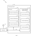
- FIG. 7 illustrates a communications device 700 that may include various components (e.g., corresponding to means-plus-function components) configured to perform operations for the techniques disclosed herein, such as the operations illustrated in FIG. 4 and other operations disclosed herein for determining transmission power levels according to signal types and RF exposure limits.
- the communications device 700 includes a processing system 702 coupled to a transceiver 708 (e.g., a transmitter and/or a receiver).
- the transceiver 708 is configured to transmit and receive signals for the communications device 700 via an antenna 710, such as the various signals as described herein.
- the processing system 702 may be configured to perform processing functions for the communications device 700, including processing signals received and/or to be transmitted by the communications device 700.
- the processing system 702 includes a processor 704 coupled to a computer-readable medium/memory 712 via a bus 706.
- the computer-readable medium/memory 712 is configured to store instructions (e.g., computer-executable code) that when executed by the processor 704, cause the processor 704 to perform the operations illustrated in FIG. 4 , or other operations for performing the various techniques discussed herein for determining transmission power levels according to signal types and RF exposure limits.
- computer-readable medium/memory 712 stores code 714 for determining a first transmission power for transmitting a first type of uplink (UL) signal; code 716 for determining a second transmission power for transmitting a second type of UL signal based on the first transmission power; and code 718 for transmitting at least one of the first UL signal according to the first transmission power or the second UL signal according to the second transmission power.
- code 714 for determining a first transmission power for transmitting a first type of uplink (UL) signal
- code 716 for determining a second transmission power for transmitting a second type of UL signal based on the first transmission power
- code 718 for transmitting at least one of the first UL signal according to the first transmission power or the second UL signal according to the second transmission power.
- NR e.g., 5G NR
- LTE Long Term Evolution
- LTE-A LTE-Advanced
- CDMA code division multiple access
- TDMA time division multiple access
- FDMA frequency division multiple access
- OFDMA orthogonal frequency division multiple access
- SC-FDMA single-carrier frequency division multiple access
- TD-SCDMA time division synchronous code division multiple access
- a CDMA network may implement a radio technology such as Universal Terrestrial Radio Access (UTRA), cdma2000, etc.
- UTRA includes Wideband CDMA (WCDMA) and other variants of CDMA.
- cdma2000 covers IS-2000, IS-95 and IS-856 standards.
- a TDMA network may implement a radio technology such as Global System for Mobile Communications (GSM).
- GSM Global System for Mobile Communications
- An OFDMA network may implement a radio technology such as NR (e.g. 5G RA), Evolved UTRA (E-UTRA), Ultra Mobile Broadband (UMB), IEEE 802.11 (Wi-Fi), IEEE 802.16 (WiMAX), IEEE 802.20, Flash-OFDMA, etc.
- E-UTRA Evolved UTRA
- UMB Ultra Mobile Broadband
- Wi-Fi Wi-Fi
- WiMAX IEEE 802.16
- IEEE 802.20 Flash-OFDMA
- UTRA and E-UTRA are part of Universal Mobile Telecommunication System (UMTS).
- LTE and LTE-A are releases of UMTS that use E-UTRA.
- UTRA, E-UTRA, UMTS, LTE, LTE-A and GSM are described in documents from an organization named "3rd Generation Partnership Project” (3GPP).
- cdma2000 and UMB are described in documents from an organization named “3rd Generation Partnership Project 2" (3GPP2).
- NR is an emerging wireless communications technology under development.
- the term “cell” can refer to a coverage area of a Node B (NB) and/or a NB subsystem serving this coverage area, depending on the context in which the term is used.
- NB Node B
- BS next generation NodeB
- AP access point
- DU distributed unit
- TRP transmission reception point
- a BS may provide communication coverage for a macro cell, a pico cell, a femto cell, and/or other types of cells.
- a macro cell may cover a relatively large geographic area (e.g., several kilometers in radius) and may allow unrestricted access by UEs with service subscription.
- a pico cell may cover a relatively small geographic area and may allow unrestricted access by UEs with service subscription.
- a femto cell may cover a relatively small geographic area (e.g., a home) and may allow restricted access by UEs having an association with the femto cell (e.g., UEs in a Closed Subscriber Group (CSG), UEs for users in the home, etc.).
- a BS for a macro cell may be referred to as a macro BS.
- a BS for a pico cell may be referred to as a pico BS.
- a BS for a femto cell may be referred to as a femto BS or a home BS.
- a UE may also be referred to as a mobile station, a terminal, an access terminal, a subscriber unit, a station, a Customer Premises Equipment (CPE), a cellular phone, a smart phone, a personal digital assistant (PDA), a wireless modem, a wireless communication device, a handheld device, a laptop computer, a cordless phone, a wireless local loop (WLL) station, a tablet computer, a camera, a gaming device, a netbook, a smartbook, an ultrabook, an appliance, a medical device or medical equipment, a biometric sensor/device, a wearable device such as a smart watch, smart clothing, smart glasses, a smart wrist band, smart jewelry (e.g., a smart ring, a smart bracelet, etc.), an entertainment device (e.g., a music device, a video device, a satellite radio, etc.), a vehicular component or sensor, a smart meter/sensor, industrial manufacturing equipment, a global positioning system device, or any other
- Some UEs may be considered machine-type communication (MTC) devices or evolved MTC (eMTC) devices.
- MTC and eMTC UEs include, for example, robots, drones, remote devices, sensors, meters, monitors, location tags, etc., that may communicate with a BS, another device (e.g., remote device), or some other entity.
- a wireless node may provide, for example, connectivity for or to a network (e.g., a wide area network such as Internet or a cellular network) via a wired or wireless communication link.
- Some UEs may be considered Internet-of-Things (IoT) devices, which may be narrowband IoT (NB-IoT) devices.
- IoT Internet-of-Things
- NB-IoT narrowband IoT
- a scheduling entity (e.g., a BS) allocates resources for communication among some or all devices and equipment within its service area or cell.
- the scheduling entity may be responsible for scheduling, assigning, reconfiguring, and releasing resources for one or more subordinate entities. That is, for scheduled communication, subordinate entities utilize resources allocated by the scheduling entity.
- Base stations are not the only entities that may function as a scheduling entity.
- a UE may function as a scheduling entity and may schedule resources for one or more subordinate entities (e.g., one or more other UEs), and the other UEs may utilize the resources scheduled by the UE for wireless communication.
- a UE may function as a scheduling entity in a peer-to-peer (P2P) network, and/or in a mesh network.
- P2P peer-to-peer
- UEs may communicate directly with one another in addition to communicating with a scheduling entity.
- computer-readable media may comprise non-transitory computer-readable media (e.g., tangible media).
- computer-readable media may comprise transitory computer-readable media (e.g., a signal). Combinations of the above should also be included within the scope of computer-readable media.
Landscapes
- Engineering & Computer Science (AREA)
- Computer Networks & Wireless Communication (AREA)
- Signal Processing (AREA)
- Physics & Mathematics (AREA)
- Probability & Statistics with Applications (AREA)
- Mobile Radio Communication Systems (AREA)
Applications Claiming Priority (3)
| Application Number | Priority Date | Filing Date | Title |
|---|---|---|---|
| US201962852795P | 2019-05-24 | 2019-05-24 | |
| US15/930,196 US11924819B2 (en) | 2019-05-24 | 2020-05-12 | Power limits based on signal type for managing maximum permissible exposure |
| PCT/US2020/032633 WO2020242760A1 (en) | 2019-05-24 | 2020-05-13 | Power limits based on signal type for managing maximum permissible exposure |
Publications (2)
| Publication Number | Publication Date |
|---|---|
| EP3977786A1 EP3977786A1 (en) | 2022-04-06 |
| EP3977786B1 true EP3977786B1 (en) | 2024-07-03 |
Family
ID=73456472
Family Applications (1)
| Application Number | Title | Priority Date | Filing Date |
|---|---|---|---|
| EP20729522.1A Active EP3977786B1 (en) | 2019-05-24 | 2020-05-13 | Power limits based on signal type for managing maximum permissible exposure |
Country Status (7)
| Country | Link |
|---|---|
| US (1) | US11924819B2 (https=) |
| EP (1) | EP3977786B1 (https=) |
| JP (1) | JP7530389B2 (https=) |
| CN (1) | CN113853816B (https=) |
| AU (2) | AU2020285565A1 (https=) |
| BR (1) | BR112021022928A2 (https=) |
| WO (1) | WO2020242760A1 (https=) |
Families Citing this family (17)
| Publication number | Priority date | Publication date | Assignee | Title |
|---|---|---|---|---|
| US10652833B2 (en) * | 2018-07-05 | 2020-05-12 | Qualcomm Incorporated | Evaluating radio frequency (RF) exposure in real time |
| EP4192157A4 (en) * | 2020-08-07 | 2023-10-04 | Guangdong Oppo Mobile Telecommunications Corp., Ltd. | Method for power control, terminal device, and network device |
| US11716695B2 (en) | 2020-09-11 | 2023-08-01 | Qualcomm Incorporated | Exception-robust time-averaged radio frequency exposure compliance continuity |
| US12323961B2 (en) | 2020-10-08 | 2025-06-03 | Qualcomm Incorporated | Allocation of transmit power in compliance with RF exposure requirements |
| CN114599078A (zh) * | 2020-12-04 | 2022-06-07 | 中兴通讯股份有限公司 | 一种电磁波吸收比值sar的控制方法、装置、设备和存储介质 |
| US12289692B2 (en) * | 2021-05-11 | 2025-04-29 | Mediatek Inc. | Method for improving transmission power management with compliance to regulations of radiofrequency exposure |
| US11432249B1 (en) * | 2021-06-16 | 2022-08-30 | Apple Inc. | Electronic devices with time domain radio-frequency exposure averaging |
| US12143179B2 (en) | 2021-06-18 | 2024-11-12 | Apple Inc. | Transmission power management for concurrent operating radios |
| US11924770B2 (en) | 2021-07-02 | 2024-03-05 | Qualcomm Incorporated | Enhanced uplink power control with lookahead |
| WO2023221025A1 (zh) * | 2022-05-19 | 2023-11-23 | 北京小米移动软件有限公司 | 波束确定方法、装置、通信设备及存储介质 |
| CN115085755B (zh) * | 2022-08-23 | 2023-01-24 | 荣耀终端有限公司 | 终端天线的控制方法和装置 |
| US12526006B2 (en) * | 2022-09-28 | 2026-01-13 | Qualcomm Incorporated | Transmit energy allocation among different radios |
| WO2024072665A1 (en) * | 2022-09-28 | 2024-04-04 | Qualcomm Incorporated | Transmit energy allocation among different radios |
| US12463326B2 (en) * | 2022-12-08 | 2025-11-04 | Intel Corporation | Antenna design and arrangement methodologies for SAR and power density human exposure optimization |
| WO2024137927A1 (en) * | 2022-12-21 | 2024-06-27 | Qualcomm Incorporated | Radio frequency exposure management for authorized exceptions |
| US12432663B2 (en) * | 2023-02-16 | 2025-09-30 | Apple Inc. | Systems and methods for high-power transmission |
| WO2024263747A1 (en) * | 2023-06-23 | 2024-12-26 | Qualcomm Incorporated | Device position determination relative to a human body |
Family Cites Families (52)
| Publication number | Priority date | Publication date | Assignee | Title |
|---|---|---|---|---|
| US7146139B2 (en) * | 2001-09-28 | 2006-12-05 | Siemens Communications, Inc. | System and method for reducing SAR values |
| KR101697596B1 (ko) * | 2009-01-29 | 2017-01-18 | 엘지전자 주식회사 | 전송 전력을 제어하는 방법 및 이를 위한 장치 |
| TWI508590B (zh) * | 2009-02-09 | 2015-11-11 | Interdigital Patent Holdings | 利用多載波無線傳送器/接收器單元之上鏈功率控制裝置及方法 |
| JP5622840B2 (ja) * | 2010-04-05 | 2014-11-12 | パナソニックインテレクチュアル プロパティ コーポレーション オブアメリカPanasonic Intellectual Property Corporation of America | 送信装置、送信電力制御方法及び送信判定方法 |
| US20120021707A1 (en) * | 2010-07-26 | 2012-01-26 | Qualcomm Incorporated | Apparatus and method for adjustment of transmitter power in a system |
| US9661588B2 (en) * | 2010-11-05 | 2017-05-23 | Sun Patent Trust | Wireless communication terminal device and power allocation method |
| US8811918B2 (en) | 2010-11-26 | 2014-08-19 | Broadcom Corporation | Distribution of transmit signal to multiple transmit antennas for reduction of measured specific absorption rate |
| EP3214875B1 (en) * | 2011-01-07 | 2020-10-07 | InterDigital Patent Holdings, Inc. | Methods, apparatus and systems for handling additional power backoff |
| KR101748107B1 (ko) | 2011-07-29 | 2017-06-15 | 후지쯔 가부시끼가이샤 | 파워 제어 방법 및 단말 장치 |
| KR20140045988A (ko) * | 2011-07-29 | 2014-04-17 | 엘지전자 주식회사 | 상향링크 전송 전력을 제어하는 단말 장치 및 그 방법 |
| US8964780B2 (en) * | 2012-01-25 | 2015-02-24 | Ofinno Technologies, Llc | Sounding in multicarrier wireless communications |
| US10206181B2 (en) * | 2012-01-30 | 2019-02-12 | Texas Instruments Incorporated | Simultaneous transmission in multiple timing advance groups |
| CN103369650B (zh) * | 2012-03-26 | 2017-02-08 | 电信科学技术研究院 | 一种上行功率控制方法及用户设备 |
| US9807709B2 (en) * | 2012-05-31 | 2017-10-31 | Interdigital Patent Holdings, Inc. | Device to-device (D2D) cross link power control |
| GB2502969A (en) * | 2012-06-11 | 2013-12-18 | Renesas Mobile Corp | Limiting the total transmit power of a multi SIM wireless device |
| EP2693815A1 (en) * | 2012-08-03 | 2014-02-05 | Panasonic Corporation | Power headroom reporting for in-device coexistence interference avoidance |
| WO2014058257A1 (en) * | 2012-10-12 | 2014-04-17 | Kt Corporation | Controlling uplink power |
| US9215686B2 (en) * | 2012-12-28 | 2015-12-15 | Telefonaktiebolaget L M Ericsson (Publ) | Wireless device, measuring node, network node, methods therein, computer program, and computer-readable storage medium |
| US9144028B2 (en) * | 2012-12-31 | 2015-09-22 | Motorola Solutions, Inc. | Method and apparatus for uplink power control in a wireless communication system |
| US9426754B2 (en) * | 2013-06-13 | 2016-08-23 | Blackberry Limited | Device dynamic total RF power compensation |
| KR102257707B1 (ko) * | 2014-01-22 | 2021-05-28 | 엘지전자 주식회사 | 전력 제어 수행 방법 및 사용자 장치 |
| EP3675566B1 (en) * | 2014-01-29 | 2022-07-06 | InterDigital Patent Holdings, Inc. | Method and apparatus of access and link adaptation for coverage enhanced wireless transmissions |
| KR102184585B1 (ko) * | 2014-03-21 | 2020-11-30 | 후아웨이 테크놀러지 컴퍼니 리미티드 | 이중 연결을 고려한 전력 제한 상황에서의 pusch/pucch 전력 스케일링 방법 및 그 장치 |
| CN106233658B (zh) * | 2014-04-20 | 2019-07-16 | Lg电子株式会社 | 在无线通信系统中发送探测参考信号的方法和终端 |
| US9781683B2 (en) * | 2014-12-16 | 2017-10-03 | Qualcomm Incorporated | Determining transmit power limits using a combined specific absorption measurement for multiple transmitters |
| US20160174168A1 (en) * | 2014-12-16 | 2016-06-16 | Qualcomm Incorporated | Avoiding transmit power limitations due to specific absorption rate constraints |
| US10271287B2 (en) * | 2015-04-13 | 2019-04-23 | Telefonaktiebolaget Lm Ericsson (Publ) | Power control in a wireless network |
| US9380541B1 (en) * | 2015-06-02 | 2016-06-28 | Qualcomm Incorporated | Managing specific absorption rate distribution to maximize transmit power of a wireless device |
| US9622187B2 (en) * | 2015-08-26 | 2017-04-11 | Qualcomm Incorporated | Real-time specific absorption rate implementation in wireless devices |
| US20170265148A1 (en) * | 2016-03-09 | 2017-09-14 | Qualcomm Incorporated | Power control based on sar and/or harq |
| US20170332333A1 (en) * | 2016-05-13 | 2017-11-16 | Qualcomm Incorporated | Managing specific absorption rate for user equipments |
| US10383067B2 (en) * | 2016-10-21 | 2019-08-13 | Asustek Computer Inc. | Method and apparatus for power headroom report for beam operation in a wireless communication system |
| US11368926B2 (en) * | 2016-12-12 | 2022-06-21 | Qualcomm Incorporated | Reporting power limit and corresponding constraint |
| EP3516908B1 (en) * | 2017-01-05 | 2020-11-18 | Telefonaktiebolaget LM Ericsson (PUBL) | Method and terminal device for adapting transmission power |
| WO2018191036A1 (en) * | 2017-04-14 | 2018-10-18 | Intel Corporation | Enhanced power management for wireless communications |
| EP3596984B1 (en) * | 2017-04-17 | 2022-07-20 | Samsung Electronics Co., Ltd. | Method and device for uplink power control |
| WO2018199691A1 (ko) * | 2017-04-28 | 2018-11-01 | 엘지전자 주식회사 | 무선 통신 시스템에서 전력을 공유하는 방법 및 장치 |
| EP3725120B1 (en) * | 2017-12-15 | 2022-05-04 | Telefonaktiebolaget LM Ericsson (publ) | Transmission power management |
| US20190222326A1 (en) * | 2018-01-15 | 2019-07-18 | Qualcomm Incorporated | Scheduling for power amplifier characterization |
| WO2019194619A1 (en) * | 2018-04-05 | 2019-10-10 | Lg Electronics Inc. | Method of transmitting or receiving signal in wireless communication system and apparatus therefor |
| MY204602A (en) * | 2018-04-13 | 2024-09-05 | Guangdong Oppo Mobile Telecommunications Corp Ltd | Method of uplink power control, terminal device and network device |
| WO2019200613A1 (zh) * | 2018-04-20 | 2019-10-24 | 华为技术有限公司 | 一种降低电磁辐射比吸收率的方法及设备 |
| EP3567940B1 (en) * | 2018-05-11 | 2022-01-26 | Apple Inc. | Techniques for controlling specific absorption rate of radio energy transmission |
| US10652833B2 (en) * | 2018-07-05 | 2020-05-12 | Qualcomm Incorporated | Evaluating radio frequency (RF) exposure in real time |
| WO2020061753A1 (zh) * | 2018-09-25 | 2020-04-02 | Oppo广东移动通信有限公司 | 无线通信的方法和终端设备 |
| WO2020073191A1 (en) * | 2018-10-09 | 2020-04-16 | Telefonaktiebolaget Lm Ericsson (Publ) | Method and apparatus for power control |
| US10447413B1 (en) * | 2018-11-13 | 2019-10-15 | Qualcomm Incorporated | Evaluating radio frequency exposure |
| US12003294B2 (en) * | 2019-04-02 | 2024-06-04 | Telefonaktiebolaget Lm Ericsson (Publ) | Control of EIRP of a radio base station |
| WO2020199221A1 (zh) * | 2019-04-04 | 2020-10-08 | Oppo广东移动通信有限公司 | 一种资源配置方法、网络设备、终端设备 |
| US11284417B2 (en) * | 2019-04-11 | 2022-03-22 | Qualcomm Incorporated | Scheduling based on available transmit power and channel state |
| CN113228755A (zh) * | 2019-04-30 | 2021-08-06 | Oppo广东移动通信有限公司 | 上行发射功率辐射限制方法及相关产品 |
| US10856236B1 (en) * | 2019-05-20 | 2020-12-01 | Qualcomm Incorporated | Fallback procedures when the path loss or spatial transmit quasi-collocation (QCL) reference from neighboring cells is failing for sounding reference signals (SRS) for positioning |
-
2020
- 2020-05-12 US US15/930,196 patent/US11924819B2/en active Active
- 2020-05-13 JP JP2021568624A patent/JP7530389B2/ja active Active
- 2020-05-13 EP EP20729522.1A patent/EP3977786B1/en active Active
- 2020-05-13 CN CN202080037672.3A patent/CN113853816B/zh active Active
- 2020-05-13 BR BR112021022928A patent/BR112021022928A2/pt unknown
- 2020-05-13 WO PCT/US2020/032633 patent/WO2020242760A1/en not_active Ceased
- 2020-05-13 AU AU2020285565A patent/AU2020285565A1/en not_active Abandoned
-
2025
- 2025-10-31 AU AU2025259991A patent/AU2025259991A1/en active Pending
Also Published As
| Publication number | Publication date |
|---|---|
| BR112021022928A2 (pt) | 2022-01-18 |
| JP7530389B2 (ja) | 2024-08-07 |
| US11924819B2 (en) | 2024-03-05 |
| KR20220011628A (ko) | 2022-01-28 |
| AU2025259991A1 (en) | 2025-11-20 |
| AU2020285565A1 (en) | 2021-12-02 |
| JP2022533647A (ja) | 2022-07-25 |
| WO2020242760A1 (en) | 2020-12-03 |
| CN113853816B (zh) | 2024-09-13 |
| CN113853816A (zh) | 2021-12-28 |
| EP3977786A1 (en) | 2022-04-06 |
| US20200374882A1 (en) | 2020-11-26 |
Similar Documents
| Publication | Publication Date | Title |
|---|---|---|
| EP3977786B1 (en) | Power limits based on signal type for managing maximum permissible exposure | |
| US10447413B1 (en) | Evaluating radio frequency exposure | |
| AU2020285552B2 (en) | Beam selection balancing maximum power exposure and link budget | |
| US12273825B2 (en) | Configurable radio frequency exposure compliance based on region | |
| EP4618437A2 (en) | Time-averaged radio frequency (rf) exposure per antenna group | |
| US12408124B2 (en) | Utilizing device state information in simultaneous radio transmission scenarios for radio frequency (RF) exposure compliance | |
| US12574865B2 (en) | Multi-radio transmission adjustment for time-averaged radio frequency exposure | |
| US20240015669A1 (en) | Duty cycle determination for radio frequency exposure evaluation | |
| US20240114469A1 (en) | Radio frequency exposure evaluation per surface | |
| US20240214953A1 (en) | Radio frequency exposure management for multiple radios | |
| EP4416863B1 (en) | Transmit power limit based on sensor spatial coverage | |
| KR102961050B1 (ko) | 최대 허용가능 노출을 관리하기 위한 신호 타입에 기반하는 전력 제한들 | |
| US20250048280A1 (en) | Enhanced transmission power limit and joint input power limit for transmissions from multiple antenna ports for radio frequency exposure compliance | |
| KR20250121971A (ko) | 다수의 라디오에 대한 무선 주파수 노출 관리 | |
| WO2024011201A1 (en) | Duty cycle determination for radio frequency exposure evaluation | |
| CN119234447A (zh) | 用于时间平均射频暴露的多无线电发送调整 |
Legal Events
| Date | Code | Title | Description |
|---|---|---|---|
| STAA | Information on the status of an ep patent application or granted ep patent |
Free format text: STATUS: UNKNOWN |
|
| STAA | Information on the status of an ep patent application or granted ep patent |
Free format text: STATUS: THE INTERNATIONAL PUBLICATION HAS BEEN MADE |
|
| PUAI | Public reference made under article 153(3) epc to a published international application that has entered the european phase |
Free format text: ORIGINAL CODE: 0009012 |
|
| STAA | Information on the status of an ep patent application or granted ep patent |
Free format text: STATUS: REQUEST FOR EXAMINATION WAS MADE |
|
| 17P | Request for examination filed |
Effective date: 20211025 |
|
| AK | Designated contracting states |
Kind code of ref document: A1 Designated state(s): AL AT BE BG CH CY CZ DE DK EE ES FI FR GB GR HR HU IE IS IT LI LT LU LV MC MK MT NL NO PL PT RO RS SE SI SK SM TR |
|
| DAV | Request for validation of the european patent (deleted) | ||
| DAX | Request for extension of the european patent (deleted) | ||
| REG | Reference to a national code |
Ref country code: DE Ref legal event code: R079 Free format text: PREVIOUS MAIN CLASS: H04W0052140000 Ipc: H04W0052160000 Ref country code: DE Ref legal event code: R079 Ref document number: 602020033332 Country of ref document: DE Free format text: PREVIOUS MAIN CLASS: H04W0052140000 Ipc: H04W0052160000 |
|
| GRAP | Despatch of communication of intention to grant a patent |
Free format text: ORIGINAL CODE: EPIDOSNIGR1 |
|
| STAA | Information on the status of an ep patent application or granted ep patent |
Free format text: STATUS: GRANT OF PATENT IS INTENDED |
|
| RIC1 | Information provided on ipc code assigned before grant |
Ipc: H04W 52/36 20090101ALN20240103BHEP Ipc: H04W 52/28 20090101ALN20240103BHEP Ipc: H04W 52/14 20090101ALN20240103BHEP Ipc: H04W 52/22 20090101ALI20240103BHEP Ipc: H04W 52/16 20090101AFI20240103BHEP |
|
| INTG | Intention to grant announced |
Effective date: 20240130 |
|
| RAP3 | Party data changed (applicant data changed or rights of an application transferred) |
Owner name: QUALCOMM INCORPORATED |
|
| GRAS | Grant fee paid |
Free format text: ORIGINAL CODE: EPIDOSNIGR3 |
|
| GRAA | (expected) grant |
Free format text: ORIGINAL CODE: 0009210 |
|
| STAA | Information on the status of an ep patent application or granted ep patent |
Free format text: STATUS: THE PATENT HAS BEEN GRANTED |
|
| AK | Designated contracting states |
Kind code of ref document: B1 Designated state(s): AL AT BE BG CH CY CZ DE DK EE ES FI FR GB GR HR HU IE IS IT LI LT LU LV MC MK MT NL NO PL PT RO RS SE SI SK SM TR |
|
| REG | Reference to a national code |
Ref country code: CH Ref legal event code: EP |
|
| REG | Reference to a national code |
Ref country code: DE Ref legal event code: R096 Ref document number: 602020033332 Country of ref document: DE |
|
| REG | Reference to a national code |
Ref country code: LT Ref legal event code: MG9D |
|
| REG | Reference to a national code |
Ref country code: NL Ref legal event code: MP Effective date: 20240703 |
|
| PG25 | Lapsed in a contracting state [announced via postgrant information from national office to epo] |
Ref country code: PT Free format text: LAPSE BECAUSE OF FAILURE TO SUBMIT A TRANSLATION OF THE DESCRIPTION OR TO PAY THE FEE WITHIN THE PRESCRIBED TIME-LIMIT Effective date: 20241104 |
|
| REG | Reference to a national code |
Ref country code: AT Ref legal event code: MK05 Ref document number: 1701065 Country of ref document: AT Kind code of ref document: T Effective date: 20240703 |
|
| PG25 | Lapsed in a contracting state [announced via postgrant information from national office to epo] |
Ref country code: NL Free format text: LAPSE BECAUSE OF FAILURE TO SUBMIT A TRANSLATION OF THE DESCRIPTION OR TO PAY THE FEE WITHIN THE PRESCRIBED TIME-LIMIT Effective date: 20240703 |
|
| PG25 | Lapsed in a contracting state [announced via postgrant information from national office to epo] |
Ref country code: PT Free format text: LAPSE BECAUSE OF FAILURE TO SUBMIT A TRANSLATION OF THE DESCRIPTION OR TO PAY THE FEE WITHIN THE PRESCRIBED TIME-LIMIT Effective date: 20241104 Ref country code: NL Free format text: LAPSE BECAUSE OF FAILURE TO SUBMIT A TRANSLATION OF THE DESCRIPTION OR TO PAY THE FEE WITHIN THE PRESCRIBED TIME-LIMIT Effective date: 20240703 |
|
| PG25 | Lapsed in a contracting state [announced via postgrant information from national office to epo] |
Ref country code: NO Free format text: LAPSE BECAUSE OF FAILURE TO SUBMIT A TRANSLATION OF THE DESCRIPTION OR TO PAY THE FEE WITHIN THE PRESCRIBED TIME-LIMIT Effective date: 20241003 |
|
| PG25 | Lapsed in a contracting state [announced via postgrant information from national office to epo] |
Ref country code: FI Free format text: LAPSE BECAUSE OF FAILURE TO SUBMIT A TRANSLATION OF THE DESCRIPTION OR TO PAY THE FEE WITHIN THE PRESCRIBED TIME-LIMIT Effective date: 20240703 Ref country code: PL Free format text: LAPSE BECAUSE OF FAILURE TO SUBMIT A TRANSLATION OF THE DESCRIPTION OR TO PAY THE FEE WITHIN THE PRESCRIBED TIME-LIMIT Effective date: 20240703 Ref country code: GR Free format text: LAPSE BECAUSE OF FAILURE TO SUBMIT A TRANSLATION OF THE DESCRIPTION OR TO PAY THE FEE WITHIN THE PRESCRIBED TIME-LIMIT Effective date: 20241004 |
|
| PG25 | Lapsed in a contracting state [announced via postgrant information from national office to epo] |
Ref country code: BG Free format text: LAPSE BECAUSE OF FAILURE TO SUBMIT A TRANSLATION OF THE DESCRIPTION OR TO PAY THE FEE WITHIN THE PRESCRIBED TIME-LIMIT Effective date: 20240703 |
|
| PG25 | Lapsed in a contracting state [announced via postgrant information from national office to epo] |
Ref country code: LV Free format text: LAPSE BECAUSE OF FAILURE TO SUBMIT A TRANSLATION OF THE DESCRIPTION OR TO PAY THE FEE WITHIN THE PRESCRIBED TIME-LIMIT Effective date: 20240703 |
|
| PG25 | Lapsed in a contracting state [announced via postgrant information from national office to epo] |
Ref country code: IS Free format text: LAPSE BECAUSE OF FAILURE TO SUBMIT A TRANSLATION OF THE DESCRIPTION OR TO PAY THE FEE WITHIN THE PRESCRIBED TIME-LIMIT Effective date: 20241103 Ref country code: AT Free format text: LAPSE BECAUSE OF FAILURE TO SUBMIT A TRANSLATION OF THE DESCRIPTION OR TO PAY THE FEE WITHIN THE PRESCRIBED TIME-LIMIT Effective date: 20240703 |
|
| PG25 | Lapsed in a contracting state [announced via postgrant information from national office to epo] |
Ref country code: CZ Free format text: LAPSE BECAUSE OF FAILURE TO SUBMIT A TRANSLATION OF THE DESCRIPTION OR TO PAY THE FEE WITHIN THE PRESCRIBED TIME-LIMIT Effective date: 20240703 Ref country code: HR Free format text: LAPSE BECAUSE OF FAILURE TO SUBMIT A TRANSLATION OF THE DESCRIPTION OR TO PAY THE FEE WITHIN THE PRESCRIBED TIME-LIMIT Effective date: 20240703 |
|
| PG25 | Lapsed in a contracting state [announced via postgrant information from national office to epo] |
Ref country code: ES Free format text: LAPSE BECAUSE OF FAILURE TO SUBMIT A TRANSLATION OF THE DESCRIPTION OR TO PAY THE FEE WITHIN THE PRESCRIBED TIME-LIMIT Effective date: 20240703 Ref country code: RS Free format text: LAPSE BECAUSE OF FAILURE TO SUBMIT A TRANSLATION OF THE DESCRIPTION OR TO PAY THE FEE WITHIN THE PRESCRIBED TIME-LIMIT Effective date: 20241003 |
|
| PG25 | Lapsed in a contracting state [announced via postgrant information from national office to epo] |
Ref country code: RS Free format text: LAPSE BECAUSE OF FAILURE TO SUBMIT A TRANSLATION OF THE DESCRIPTION OR TO PAY THE FEE WITHIN THE PRESCRIBED TIME-LIMIT Effective date: 20241003 Ref country code: PL Free format text: LAPSE BECAUSE OF FAILURE TO SUBMIT A TRANSLATION OF THE DESCRIPTION OR TO PAY THE FEE WITHIN THE PRESCRIBED TIME-LIMIT Effective date: 20240703 Ref country code: NO Free format text: LAPSE BECAUSE OF FAILURE TO SUBMIT A TRANSLATION OF THE DESCRIPTION OR TO PAY THE FEE WITHIN THE PRESCRIBED TIME-LIMIT Effective date: 20241003 Ref country code: LV Free format text: LAPSE BECAUSE OF FAILURE TO SUBMIT A TRANSLATION OF THE DESCRIPTION OR TO PAY THE FEE WITHIN THE PRESCRIBED TIME-LIMIT Effective date: 20240703 Ref country code: IS Free format text: LAPSE BECAUSE OF FAILURE TO SUBMIT A TRANSLATION OF THE DESCRIPTION OR TO PAY THE FEE WITHIN THE PRESCRIBED TIME-LIMIT Effective date: 20241103 Ref country code: HR Free format text: LAPSE BECAUSE OF FAILURE TO SUBMIT A TRANSLATION OF THE DESCRIPTION OR TO PAY THE FEE WITHIN THE PRESCRIBED TIME-LIMIT Effective date: 20240703 Ref country code: GR Free format text: LAPSE BECAUSE OF FAILURE TO SUBMIT A TRANSLATION OF THE DESCRIPTION OR TO PAY THE FEE WITHIN THE PRESCRIBED TIME-LIMIT Effective date: 20241004 Ref country code: FI Free format text: LAPSE BECAUSE OF FAILURE TO SUBMIT A TRANSLATION OF THE DESCRIPTION OR TO PAY THE FEE WITHIN THE PRESCRIBED TIME-LIMIT Effective date: 20240703 Ref country code: ES Free format text: LAPSE BECAUSE OF FAILURE TO SUBMIT A TRANSLATION OF THE DESCRIPTION OR TO PAY THE FEE WITHIN THE PRESCRIBED TIME-LIMIT Effective date: 20240703 Ref country code: CZ Free format text: LAPSE BECAUSE OF FAILURE TO SUBMIT A TRANSLATION OF THE DESCRIPTION OR TO PAY THE FEE WITHIN THE PRESCRIBED TIME-LIMIT Effective date: 20240703 Ref country code: BG Free format text: LAPSE BECAUSE OF FAILURE TO SUBMIT A TRANSLATION OF THE DESCRIPTION OR TO PAY THE FEE WITHIN THE PRESCRIBED TIME-LIMIT Effective date: 20240703 Ref country code: AT Free format text: LAPSE BECAUSE OF FAILURE TO SUBMIT A TRANSLATION OF THE DESCRIPTION OR TO PAY THE FEE WITHIN THE PRESCRIBED TIME-LIMIT Effective date: 20240703 |
|
| REG | Reference to a national code |
Ref country code: DE Ref legal event code: R097 Ref document number: 602020033332 Country of ref document: DE |
|
| PG25 | Lapsed in a contracting state [announced via postgrant information from national office to epo] |
Ref country code: DK Free format text: LAPSE BECAUSE OF FAILURE TO SUBMIT A TRANSLATION OF THE DESCRIPTION OR TO PAY THE FEE WITHIN THE PRESCRIBED TIME-LIMIT Effective date: 20240703 Ref country code: RO Free format text: LAPSE BECAUSE OF FAILURE TO SUBMIT A TRANSLATION OF THE DESCRIPTION OR TO PAY THE FEE WITHIN THE PRESCRIBED TIME-LIMIT Effective date: 20240703 Ref country code: SM Free format text: LAPSE BECAUSE OF FAILURE TO SUBMIT A TRANSLATION OF THE DESCRIPTION OR TO PAY THE FEE WITHIN THE PRESCRIBED TIME-LIMIT Effective date: 20240703 |
|
| PG25 | Lapsed in a contracting state [announced via postgrant information from national office to epo] |
Ref country code: EE Free format text: LAPSE BECAUSE OF FAILURE TO SUBMIT A TRANSLATION OF THE DESCRIPTION OR TO PAY THE FEE WITHIN THE PRESCRIBED TIME-LIMIT Effective date: 20240703 |
|
| PG25 | Lapsed in a contracting state [announced via postgrant information from national office to epo] |
Ref country code: IT Free format text: LAPSE BECAUSE OF FAILURE TO SUBMIT A TRANSLATION OF THE DESCRIPTION OR TO PAY THE FEE WITHIN THE PRESCRIBED TIME-LIMIT Effective date: 20240703 Ref country code: SK Free format text: LAPSE BECAUSE OF FAILURE TO SUBMIT A TRANSLATION OF THE DESCRIPTION OR TO PAY THE FEE WITHIN THE PRESCRIBED TIME-LIMIT Effective date: 20240703 |
|
| PLBE | No opposition filed within time limit |
Free format text: ORIGINAL CODE: 0009261 |
|
| STAA | Information on the status of an ep patent application or granted ep patent |
Free format text: STATUS: NO OPPOSITION FILED WITHIN TIME LIMIT |
|
| 26N | No opposition filed |
Effective date: 20250404 |
|
| PGFP | Annual fee paid to national office [announced via postgrant information from national office to epo] |
Ref country code: DE Payment date: 20250409 Year of fee payment: 6 |
|
| PGFP | Annual fee paid to national office [announced via postgrant information from national office to epo] |
Ref country code: FR Payment date: 20250409 Year of fee payment: 6 |
|
| PG25 | Lapsed in a contracting state [announced via postgrant information from national office to epo] |
Ref country code: SE Free format text: LAPSE BECAUSE OF FAILURE TO SUBMIT A TRANSLATION OF THE DESCRIPTION OR TO PAY THE FEE WITHIN THE PRESCRIBED TIME-LIMIT Effective date: 20240703 |
|
| REG | Reference to a national code |
Ref country code: CH Ref legal event code: H13 Free format text: ST27 STATUS EVENT CODE: U-0-0-H10-H13 (AS PROVIDED BY THE NATIONAL OFFICE) Effective date: 20251223 |
|
| PG25 | Lapsed in a contracting state [announced via postgrant information from national office to epo] |
Ref country code: LU Free format text: LAPSE BECAUSE OF NON-PAYMENT OF DUE FEES Effective date: 20250513 |
|
| PG25 | Lapsed in a contracting state [announced via postgrant information from national office to epo] |
Ref country code: CH Free format text: LAPSE BECAUSE OF NON-PAYMENT OF DUE FEES Effective date: 20250531 |
|
| REG | Reference to a national code |
Ref country code: BE Ref legal event code: MM Effective date: 20250531 |
|
| PG25 | Lapsed in a contracting state [announced via postgrant information from national office to epo] |
Ref country code: MC Free format text: LAPSE BECAUSE OF FAILURE TO SUBMIT A TRANSLATION OF THE DESCRIPTION OR TO PAY THE FEE WITHIN THE PRESCRIBED TIME-LIMIT Effective date: 20240703 |
|
| PGFP | Annual fee paid to national office [announced via postgrant information from national office to epo] |
Ref country code: GB Payment date: 20260320 Year of fee payment: 7 |
|
| PG25 | Lapsed in a contracting state [announced via postgrant information from national office to epo] |
Ref country code: IE Free format text: LAPSE BECAUSE OF NON-PAYMENT OF DUE FEES Effective date: 20250513 |
|
| PG25 | Lapsed in a contracting state [announced via postgrant information from national office to epo] |
Ref country code: BE Free format text: LAPSE BECAUSE OF NON-PAYMENT OF DUE FEES Effective date: 20250531 |