EP3977589B1 - Verfahren und vorrichtung zur energiegewinnung und zum laden von wiederaufladbaren energiespeichervorrichtungen - Google Patents
Verfahren und vorrichtung zur energiegewinnung und zum laden von wiederaufladbaren energiespeichervorrichtungen Download PDFInfo
- Publication number
- EP3977589B1 EP3977589B1 EP20725574.6A EP20725574A EP3977589B1 EP 3977589 B1 EP3977589 B1 EP 3977589B1 EP 20725574 A EP20725574 A EP 20725574A EP 3977589 B1 EP3977589 B1 EP 3977589B1
- Authority
- EP
- European Patent Office
- Prior art keywords
- power
- storage device
- batt1
- voltage converter
- path
- Prior art date
- Legal status (The legal status is an assumption and is not a legal conclusion. Google has not performed a legal analysis and makes no representation as to the accuracy of the status listed.)
- Active
Links
Images


Classifications
-
- H—ELECTRICITY
- H02—GENERATION; CONVERSION OR DISTRIBUTION OF ELECTRIC POWER
- H02J—ELECTRIC POWER NETWORKS; CIRCUIT ARRANGEMENTS OR SYSTEMS FOR SUPPLYING OR DISTRIBUTING ELECTRIC POWER; SYSTEMS FOR STORING ELECTRIC ENERGY
- H02J50/00—Circuit arrangements or systems for wireless supply or distribution of electric power
- H02J50/001—Energy harvesting or scavenging
-
- H—ELECTRICITY
- H02—GENERATION; CONVERSION OR DISTRIBUTION OF ELECTRIC POWER
- H02J—ELECTRIC POWER NETWORKS; CIRCUIT ARRANGEMENTS OR SYSTEMS FOR SUPPLYING OR DISTRIBUTING ELECTRIC POWER; SYSTEMS FOR STORING ELECTRIC ENERGY
- H02J7/00—Circuit arrangements for charging or discharging batteries or for supplying loads from batteries
- H02J7/34—Parallel operation in networks using both storage and other DC sources, e.g. providing buffering
- H02J7/342—The other DC source being a battery actively interacting with the first one, i.e. battery to battery charging
-
- H—ELECTRICITY
- H02—GENERATION; CONVERSION OR DISTRIBUTION OF ELECTRIC POWER
- H02J—ELECTRIC POWER NETWORKS; CIRCUIT ARRANGEMENTS OR SYSTEMS FOR SUPPLYING OR DISTRIBUTING ELECTRIC POWER; SYSTEMS FOR STORING ELECTRIC ENERGY
- H02J7/00—Circuit arrangements for charging or discharging batteries or for supplying loads from batteries
- H02J7/50—Circuit arrangements for charging or discharging batteries or for supplying loads from batteries acting upon multiple batteries simultaneously or sequentially
-
- H—ELECTRICITY
- H02—GENERATION; CONVERSION OR DISTRIBUTION OF ELECTRIC POWER
- H02J—ELECTRIC POWER NETWORKS; CIRCUIT ARRANGEMENTS OR SYSTEMS FOR SUPPLYING OR DISTRIBUTING ELECTRIC POWER; SYSTEMS FOR STORING ELECTRIC ENERGY
- H02J7/00—Circuit arrangements for charging or discharging batteries or for supplying loads from batteries
- H02J7/80—Circuit arrangements for charging or discharging batteries or for supplying loads from batteries including monitoring or indicating arrangements
- H02J7/82—Control of state of charge [SOC]
-
- H—ELECTRICITY
- H02—GENERATION; CONVERSION OR DISTRIBUTION OF ELECTRIC POWER
- H02J—ELECTRIC POWER NETWORKS; CIRCUIT ARRANGEMENTS OR SYSTEMS FOR SUPPLYING OR DISTRIBUTING ELECTRIC POWER; SYSTEMS FOR STORING ELECTRIC ENERGY
- H02J7/00—Circuit arrangements for charging or discharging batteries or for supplying loads from batteries
- H02J7/855—Circuit arrangements for charging or discharging batteries or for supplying loads from batteries with circuits adapted for supplying loads from the battery
-
- H—ELECTRICITY
- H02—GENERATION; CONVERSION OR DISTRIBUTION OF ELECTRIC POWER
- H02J—ELECTRIC POWER NETWORKS; CIRCUIT ARRANGEMENTS OR SYSTEMS FOR SUPPLYING OR DISTRIBUTING ELECTRIC POWER; SYSTEMS FOR STORING ELECTRIC ENERGY
- H02J7/00—Circuit arrangements for charging or discharging batteries or for supplying loads from batteries
- H02J7/90—Regulation of charging or discharging current or voltage
- H02J7/96—Regulation of charging or discharging current or voltage in response to battery voltage
-
- H—ELECTRICITY
- H02—GENERATION; CONVERSION OR DISTRIBUTION OF ELECTRIC POWER
- H02M—APPARATUS FOR CONVERSION BETWEEN AC AND AC, BETWEEN AC AND DC, OR BETWEEN DC AND DC, AND FOR USE WITH MAINS OR SIMILAR POWER SUPPLY SYSTEMS; CONVERSION OF DC OR AC INPUT POWER INTO SURGE OUTPUT POWER; CONTROL OR REGULATION THEREOF
- H02M3/00—Conversion of DC power input into DC power output
- H02M3/02—Conversion of DC power input into DC power output without intermediate conversion into AC
- H02M3/04—Conversion of DC power input into DC power output without intermediate conversion into AC by static converters
- H02M3/10—Conversion of DC power input into DC power output without intermediate conversion into AC by static converters using discharge tubes with control electrode or semiconductor devices with control electrode
- H02M3/145—Conversion of DC power input into DC power output without intermediate conversion into AC by static converters using discharge tubes with control electrode or semiconductor devices with control electrode using devices of a triode or transistor type requiring continuous application of a control signal
- H02M3/155—Conversion of DC power input into DC power output without intermediate conversion into AC by static converters using discharge tubes with control electrode or semiconductor devices with control electrode using devices of a triode or transistor type requiring continuous application of a control signal using semiconductor devices only
- H02M3/156—Conversion of DC power input into DC power output without intermediate conversion into AC by static converters using discharge tubes with control electrode or semiconductor devices with control electrode using devices of a triode or transistor type requiring continuous application of a control signal using semiconductor devices only with automatic control of output voltage or current, e.g. switching regulators
- H02M3/158—Conversion of DC power input into DC power output without intermediate conversion into AC by static converters using discharge tubes with control electrode or semiconductor devices with control electrode using devices of a triode or transistor type requiring continuous application of a control signal using semiconductor devices only with automatic control of output voltage or current, e.g. switching regulators including plural semiconductor devices as final control devices for a single load
- H02M3/1582—Buck-boost converters
-
- H—ELECTRICITY
- H02—GENERATION; CONVERSION OR DISTRIBUTION OF ELECTRIC POWER
- H02J—ELECTRIC POWER NETWORKS; CIRCUIT ARRANGEMENTS OR SYSTEMS FOR SUPPLYING OR DISTRIBUTING ELECTRIC POWER; SYSTEMS FOR STORING ELECTRIC ENERGY
- H02J2207/00—Details of circuit arrangements for charging or discharging batteries or supplying loads from batteries
- H02J2207/20—Charging or discharging characterised by the power electronics converter
-
- H—ELECTRICITY
- H02—GENERATION; CONVERSION OR DISTRIBUTION OF ELECTRIC POWER
- H02J—ELECTRIC POWER NETWORKS; CIRCUIT ARRANGEMENTS OR SYSTEMS FOR SUPPLYING OR DISTRIBUTING ELECTRIC POWER; SYSTEMS FOR STORING ELECTRIC ENERGY
- H02J50/00—Circuit arrangements or systems for wireless supply or distribution of electric power
- H02J50/20—Circuit arrangements or systems for wireless supply or distribution of electric power using microwaves or radio frequency waves
-
- H—ELECTRICITY
- H02—GENERATION; CONVERSION OR DISTRIBUTION OF ELECTRIC POWER
- H02J—ELECTRIC POWER NETWORKS; CIRCUIT ARRANGEMENTS OR SYSTEMS FOR SUPPLYING OR DISTRIBUTING ELECTRIC POWER; SYSTEMS FOR STORING ELECTRIC ENERGY
- H02J7/00—Circuit arrangements for charging or discharging batteries or for supplying loads from batteries
- H02J7/34—Parallel operation in networks using both storage and other DC sources, e.g. providing buffering
- H02J7/345—Parallel operation in networks using both storage and other DC sources, e.g. providing buffering using capacitors as storage or buffering devices
Definitions
- the invention relates to a method and device for energy harvesting. More specifically, it relates to a method and device for charging rechargeable energy storage devices.
- voltage converters for extracting energy from an energy harvester and charging an energy storage device are well known in the art.
- an integrated circuit comprising a voltage converter is described for transferring energy from an energy harvester to a rechargeable storage device.
- the energy stored in the rechargeable storage device is then used as a power source for an application load.
- the application load can be coupled directly or indirectly to the storage device.
- An indirect coupling is for example established by placing an auxiliary voltage converter between the storage device and the application load and wherein the auxiliary voltage converter is configured for regulating a specific required voltage for the application load.
- Another example of harvester device could be found in WO2016196640 .
- a variety of energy harvesters can be used as energy sources such as for example photovoltaic cells (PV), thermoelectric generators (TEG), piezoelectric energy generators and electromagnetic energy generators.
- the rechargeable storage device is for example a rechargeable battery such as Li-ion battery, a supercapacitor or a conventional capacitor.
- One of the problems with the known energy harvesting systems is that when initially starting with a depleted rechargeable storage device, it takes a long time to initially charge the rechargeable storage device with energy from the energy harvester. As a consequence, it also takes a long time before the application load can receive power from the rechargeable storage device and start operating. Especially if the rechargeable storage device is a supercapacitor, being at zero Volt when fully de-charged, the charging time of the supercapacitor can be very long. But also charging rechargeable batteries to a required charging level for being ready supplying power to an application load during a sufficiently long time period can take a considerable long charging time.
- a second problem is related to the variable conditions inherent to energy harvesting systems which result in situations where the energy harvester is not supplying continuously energy over a longer period of time, e.g. over time periods of multiple days.
- energy harvesting can be interrupted over considerable long time intervals, e.g. time intervals of several hours, which degrades the reliability and long term functionality of the application load.
- this can result in an application load being stopped from operating.
- a further object is that the application load can continue to operate even under conditions wherein the energy harvester is interrupted over a longer period of time, for example interruptions of several hours or even several days.
- the object is also to maximize the extraction and use of energy from the energy harvester.
- a method for energy harvesting and supplying electrical power to an application load is provided.
- the application load to be powered with the energy harvested can be any type of application such as for example portable devices, sensors, external circuits, or wireless transmitters.
- the method for energy harvesting uses a voltage converter system for converting input power into output power and for charging at least a first and a second rechargeable storage device.
- the voltage converter system comprises one or more voltage converters.
- the method according to the invention comprises steps of coupling a first power input path between an energy harvester and the voltage converter system for transferring input power from the energy harvester to the voltage converter system, monitoring a parameter V Batt1 and a parameter V Batt2 indicative of a charging level of respectively the first rechargeable storage device and the second rechargeable storage device and coupling the first rechargeable storage device to an application load such that the first rechargeable storage device when charged can supply power to the application load.
- the parameters V Batt1 and V Batt2 correspond to a voltage of respectively the first and the second rechargeable storage device. In other embodiments, the parameters V Batt1 and V Batt2 correspond to respectively a first and a second accumulated charge acquired by for example charge counters counting accumulated charges during the charging process of the first and second rechargeable storage devices.
- the method further comprises a step of coordinating charging of the first and the second rechargeable storage device by repetitively performing sub-steps of:
- the method according to the invention further comprises a step of transferring energy from the second rechargeable storage device to the first rechargeable storage device if i) the parameter V Batt1 of the first rechargeable storage device has dropped below a critical threshold value V Batt1-SW , with V Batt1-SW ⁇ V Batt1-low , and if ii) the parameter V Batt2 is equal or above a predefined threshold value V Batt2-low .
- the step of transferring energy comprises sub-steps of: 1b) decoupling the first power input path, 2b) coupling a second power input path between the second rechargeable storage device and the voltage converter system for transferring input power from the second rechargeable storage device to the voltage converter system, and 3b) operating the voltage converter system for charging the first rechargeable storage device with energy from the second rechargeable storage device until the parameter V Batt1 of the first rechargeable storage device has reached the upper threshold value V Batt1-up .
- the application load can continue to operate during both the entire charging process of the second rechargeable storage device and during the entire process of repetitively re-charging the first rechargeable storage device. In this way, the use of the application load is not disturbing or interrupting the energy harvesting and the storage of energy in the second rechargeable storage device.
- the second rechargeable storage device can be used to recharge the first storage device when the energy harvester is not operating.
- the second rechargeable storage device can be a dedicated storage device operating at for example a different maximum voltage than the first rechargeable storage device and having a large energy storage capacity.
- the two storage devices can also be made of a different technology, the first rechargeable storage device can for example be a rechargeable battery such as a lithium ion battery, and the second rechargeable storage device can for example be a supercapacitor. In this way, if the energy harvester is interrupted over a long time period, the energy stored in the second rechargeable storage device can be transferred to the first rechargeable storage device and be used to continue power the application load.
- the second rechargeable storage device has an energy storage capacity that is more than five times, more preferably more than ten times, larger than the energy storage capacity of the first rechargeable storage device.
- an integrated circuit for energy harvesting comprising a voltage converter system that is suitable for converting input power into output power for charging at least two rechargeable storage devices, a first terminal connectable with an energy harvester, a second terminal connectable with a first rechargeable storage device, a third terminal connectable with a second rechargeable storage device, a controller for controlling the voltage converter system, a plurality of power input paths comprising at least a first power input path for transferring input power from the first terminal to the voltage converter system, a plurality of power output paths comprising at least a first power output path for transferring output power from the voltage converter system to the second terminal and a second power output path for transferring output power from the voltage converter system to the third terminal, a monitoring unit coupled with the controller and configured for monitoring a parameter V Batt1 and a parameter V Batt2 indicative of a charging level of respectively the first rechargeable storage device and the second rechargeable storage device when connected to respectively the second and third terminal.
- the parameter V Batt1 and the parameter V Batt2 correspond for example to a voltage sensed at respectively the second and third terminal.
- the integrated circuit for energy harvesting is characterized in that the plurality of power input paths comprises a second power input path for transferring input power from the third terminal to the voltage converter system, and in that the voltage converter system comprises an input selection circuit for selecting a power input path from the plurality of power input paths so as to receive an input power via the power input path selected and an output selection circuit for selecting a power output path from the plurality of power output paths so as to output an output power via the power output path selected, and in that the controller is configured to form and to switch between a number of specific combinations of a power input and a power output path based on a comparison of the parameter V Batt1 with first predefined threshold values and/or a comparison of the parameter V Batt2 with second predefined threshold values.
- the specific combinations the controller can form and switch comprise: i) a first combination formed by selecting the first power input path and selecting the first power output path, ii) a second combination formed by selecting the first power input path and selecting the second power output path, iii) a third combination formed by selecting the second power input path and selecting the first power output path.
- Selecting "a" power input path from the plurality of power input paths so as to receive an input power via the power input path selected has to be construed as selecting "one" power input path from the plurality of power input paths so as to only receive the input power via the power input path selected.
- selecting "a" power output path from the plurality of power output paths so as to output an output power via the power output path selected has to be construed as selecting "one" power output path from the plurality of power output paths so as to output the output power only via the power output path selected.
- a second rechargeable storage device coupled to this third terminal can not only be charged with energy from the energy harvester for forming an energy reservoir, but can also be used as an alternative energy source for charging the first rechargeable storage device when the energy harvester is not operating.
- the voltage converter system can be used to transfer charges from the second rechargeable storage device, being coupled to the third terminal, to the first rechargeable storage device, being coupled to the second terminal. In this way, even if the energy harvester is not operating, the first storage device can be continued to be charged such that the application load coupled to the first storage device can continue to operate.
- the controller of the integrated circuit is further configured for: switching from the first combination to the second combination if the parameter V Batt1 becomes equal or larger than an upper threshold value V Batt1-up and if the parameter V Batt2 is lower than an upper threshold value V Batt2-max , switching from the second combination to the first combination if the parameter V Batt1 has decreased from the upper threshold value V Batt1-up down to a lower threshold value V Batt1-low , with V Batt1-low ⁇ V Batt1-up , and switching from the first combination to the third combination if the parameter V Batt1 has decreased from the lower threshold value V Batt1-low down to a critical threshold value V Batt1-SW , with V Batt1-SW ⁇ V Batt1-low , and if V Batt2 is above a lower threshold value V Batt2-low , with V Batt2-low ⁇ V Batt2-max .
- the integrated circuit comprises a fourth terminal connectable with an auxiliary energy source such as a primary battery
- the plurality of power input paths comprises a third input path for transferring input power from the fourth terminal to the voltage converter system, and wherein the specific combinations of input/output paths comprise a fourth combination formed by selecting the third power input path and selecting the first power output path.
- the voltage converter system comprises a voltage converter for converting input power received via the selected power input path into output power outputted via the selected power output path, and wherein the voltage converter is one of the following: a boost voltage converter, a buck voltage converter or a buck-boost voltage converter.
- a boost voltage converter for converting input power received via the selected power input path into output power outputted via the selected power output path
- the voltage converter is one of the following: a boost voltage converter, a buck voltage converter or a buck-boost voltage converter.
- a single voltage converter is used in combination with the input and output selection circuits.
- a method for energy harvesting and supplying electrical power to an application load makes use of a system for energy harvesting comprising a voltage converter system.
- a voltage converter system has to be construed as a system for converting input power received from an energy source into output power for charging a storage device.
- the energy source for example an energy harvester, is supplying input power at an input voltage V in and the voltage converter system is outputting output power at an output voltage V out corresponding to the voltage of the storage device.
- the input voltage V in can be higher or lower than the output voltage V out .
- the voltage converter system comprises one or more voltage converters and detailed embodiments of various voltage converter systems will be further described below.
- An example of a voltage converter is a DC-DC boost converter, a DC-DC buck converter or a DC-DC buck/boost converter.
- the voltage converter system is part of an integrated circuit, generally named power management integrated circuit (PMIC).
- PMIC power management integrated circuit
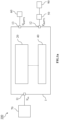
- a system 100 for energy harvesting comprises a power management integrated circuit (PMIC) 1 comprising a voltage converter system 20 and a controller 40 for controlling the voltage converter system.
- An energy harvester 70 is coupled to a first terminal 11, which is an input terminal for receiving power from the energy harvester at an input voltage V in .
- the PMIC 1 comprises a second terminal 12, being an output terminal that is coupled to a first rechargeable storage device 50.
- the application load 90 is coupled to the first storage device 50 by a direct connection.
- a voltage regulator can for example be placed between the first storage device and the application load to generate a required voltage for the application load that is different from the voltage of the first storage device.
- the PMIC shown on Fig.1a comprises a third terminal 13 being connected with a second rechargeable storage device 60.
- the first rechargeable storage device is for example a rechargeable battery, a capacitor or supercapacitor and similarly, the second rechargeable storage device can also be either a rechargeable battery, a capacitor or supercapacitor.
- a further example of a system for energy harvesting is schematically shown wherein a first application load 90a is coupled to a first storage device 50 and wherein a second application load 90b is coupled to a second storage device 60.
- the first application load is for example a low-power load, for instance for monitoring purposes
- the second application load is for example a higher power load, for instance for communication means or actuation means.
- the method for energy harvesting comprises steps of coupling a first power input path between an energy harvester and the voltage converter system for transferring input power from the energy harvester to the voltage converter system 20, monitoring a parameter V Batt1 and a parameter V Batt2 indicative of a charging level of respectively the first rechargeable storage device 50 and the second rechargeable storage device 60 and coupling the first rechargeable storage device to an application load 90 such that the first rechargeable storage device when charged can supply power to the application load.
- the parameters V Batt1 and V Batt2 correspond to a voltage of respectively the first and the second rechargeable storage device obtained by a voltage measurement. In other embodiments, the parameters V Batt1 and V Batt2 correspond to an amount of charges acquired with a charge counter.
- the first rechargeable storage device 50 can be used as a power supply for the application load 90.
- the voltage threshold V Batt1-up does not necessarily correspond to a fully charged storage device but it can be a value indicating that the first storage device is sufficiently charged to start supplying power to the application load.
- the method according to the invention further comprises a step of coordinating charging of the first and the second rechargeable storage device by repetitively performing sub-steps 1a) to 4a) outlined here below.
- Sub-step 1a) corresponds to coupling a first power output path between the voltage converter system and the first rechargeable storage device for transferring output power from the voltage converter system to the first rechargeable storage device.
- Sub-step 2a) corresponds to operating the voltage converter system for charging the first rechargeable storage device with energy from the energy harvester until the parameter V Batt1 has reached an upper threshold value V Batt1-up . Hence, during the charging of the first rechargeable storage device, charges are being transferred from the energy harvester to the first rechargeable storage device.
- Sub-step 3a) is performed if the conditions are fulfilled that V Batt1 has reached the upper threshold value V Batt1-up and that V Batt2 is below an upper threshold value V Batt2-max .
- Sub-step 3a) corresponds to: i) decoupling the first power output path and coupling a second power output path between the voltage converter system 20 and the second rechargeable storage device 60 for transferring output power from the voltage converter system to the second rechargeable storage device, and ii) operating the voltage converter system for charging the second rechargeable storage device with energy from the energy harvester. Hence, during the charging of the second rechargeable storage device, charges are being transferred from the energy harvester to the second rechargeable storage device.
- Sub-step 4a) corresponds to decoupling the second power output path and restart at step 1a) if during the charging of the second rechargeable storage device the parameter V Batt1 has subsequently decreased from the upper threshold value V Batt1-up down to a lower threshold value V Batt1-low , with V Batt1-low ⁇ V Batt1-up .
- the second rechargeable storage device 60 is being charged while maintaining the first rechargeable storage device 50 charged between charging levels V Batt1-low and V Batt1-up .
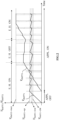
- Fig.2 a process for charging the first and second rechargeable storage device according to the method of the present disclosure is illustrated.
- the variation of the parameters V Batt1 and V Batt2 are shown as function of time, illustrating the charging and de-charging of respectively the first and second rechargeable storage device.
- the first storage device 50 remains charged by keeping the parameter V Batt1 of the first storage device 50 between the lower threshold value V Batt1-low and the upper threshold value V Batt1-up , and in parallel the second storage device 60 is being charged with energy from the energy harvester while the first storage device 50 is supplying power to the application load.
- the application load continues to be operated while the second storage device 60 is being charged such that there is no interruption in the operation of the application load.
- This is schematically illustrated with the example shown on Fig.2 where the time period wherein the application load is on and off is respectively indicated by "APPL. ON” and "APPL. OFF".
- the first storage device is de-charging as indicated by the parameter V Batt1 of the first storage device decreasing from the upper threshold value V Batt1-up down to the lower threshold value V Batt1-low .
- the lower threshold value V Batt1-low is typically a value selected such that the first storage device is still sufficiently charged to provide electrical power to the application load.
- the values selected for the lower and upper threshold values for the first storage device depend on the type of storage device used, e.g. a rechargeable battery or a capacitor a or supercapacitor.
- the upper threshold V Batt1-up is not necessarily equal to the maximum allowable voltage value V Batt1-max of the first rechargeable storage device, V Batt1-up can for example be a value that is smaller than V Batt1-max .
- the method according to the present disclosure is characterized in that the method comprises a further step of transferring energy from the second rechargeable storage device to the first rechargeable storage device if i) the parameter V Batt1 of the first rechargeable storage device has dropped below a critical threshold value V Batt1-SW , with V Batt1-SW ⁇ V Batt1-low , and if ii) the parameter V Batt2 is equal or above a predefined threshold value V Batt2-low .
- the predefined threshold value V Batt2-low is a value indicating that the second rechargeable storage device is charged to a minimum charging level allowing to transfer charges from the second to the first rechargeable storage device.
- the step of transferring energy from the second to the first rechargeable storage device comprises sub-steps of: 1b) decoupling the first power input path, 2b) coupling a second power input path between the second rechargeable storage device and the voltage converter system for transferring input power from the second rechargeable storage device to the voltage converter system, and 3b) operating the voltage converter system for charging the first rechargeable storage device with energy from the second rechargeable storage device until the parameter V Batt1 of the first rechargeable storage device has reached the upper threshold value V Batt1-up .
- the transferring of energy from the second rechargeable storage device 60 to the first rechargeable storage device 50 comprises a further sub-step 4b) in case the parameter V Batt1 has reached the upper threshold value V Batt1-up .
- Sub-step 4b) corresponds to performing at least one or a combination of the following steps: i) decoupling the first power output path 32a and/or decoupling the second power input path 31b, ii) coupling the first power input path 31a and coupling the second power output path 32b, iii) stop operating the voltage converter system 20.
- step ii) of coupling the first power input path 31a and coupling the second power output path 32b is applied, then if the energy harvester is supplying power, the second rechargeable storage device will continue to be charged with energy from the energy harvester.
- the transferring of energy from the second to the first storage device when the parameter V Batt1 of the first storage device 50 has dropped below the critical threshold level V Batt1-SW is also illustrated on Fig.2 .
- Such a drop of the parameter V Batt1 typically happens when the energy harvester is off or when the application load is consuming more power than the power the energy harvester is supplying.
- Fig.2 when the energy harvester is switching from an on state indicated by "E.H. ON" to an off state indicated by "E.H. OFF”, nor the first nor the second storage device can be charged with energy from the energy harvester.
- V Batt1 when decreasing to V Batt1-low will continue to further decrease until V Batt1-SW is reached.
- V Batt1-SW when V Batt1 drops below V Batt1-SW , the first storage device is recharged by using energy from the second storage device and when the energy harvester becomes again operational and supplies power, the energy of the energy harvester is used again to maintain the first storage device charged and to continue charging the second storage device, as discussed above.
- the voltages of the first and second storage devices can be independent from each other and the first and second storage device can also be made of different technologies.
- the first rechargeable storage device can be a Li-ion battery operating between 3.6 V and 4.0 V while the second rechargeable storage device can be a supercapacitor chargeable up to a maximum voltage of 2.7 V.
- the second rechargeable storage device 60 has an energy storage capacity that is more than five times, preferably more than ten times, larger than the energy capacity of the first rechargeable storage device 50.
- the second storage device is forming a large energy reservoir that is suitable to maintain the application load operational under conditions where the energy harvester is down for a longer timer period.
- it will also take less time to charge the first storage device and start operating the application load.
- the second parameter V Batt2 allows to determine if the second storage device is sufficiently charged for providing output power and this can for example be determined by comparing V Batt2 with a predefined threshold value V Batt2-low , wherein the second storage device is considered charged if V Batt2 ⁇ V Batt2-low .
- the second storage device is then considered not sufficiently charged to supply an output power if V Batt2 ⁇ V Batt2-low .
- the step of charging the first 50 and the second 60 rechargeable storage device comprises a further sub-step 3a) iii) if the situation occurs wherein V Batt2 has reached the upper threshold value V Batt2-max .
- the sub-step 3a) iii) corresponds to performing at least one of the following: a) decoupling the second power output path 32b and/or decoupling the first power input path 31a, b) stop operating the voltage converter system 20, c) coupling the first power input path 31a and coupling the first power output path 32b.
- an initial step is performed of precharging the second rechargeable storage device 60 up to a predefined charging level.
- the precharging of the second rechargeable storage device comprises steps of: i) coupling the second power output path 32b between the voltage converter system 20 and the second rechargeable storage device 60 for transferring output power from the voltage converter system to the second rechargeable storage device 60, and ii) operating the voltage converter system 20 for charging the second rechargeable storage device 60 with energy from the energy harvester 70 until the parameter V Batt2 has reached a predefined threshold value V Batt2-PC , with V Batt2-PC ⁇ V Batt2-low .
- the method of the present invention comprises an additional step for the situation where the parameter V Batt1 has dropped below the critical threshold value V Batt1-SW and where the second rechargeable storage device 60 is not charged and hence no charges can be transferred from the second to the first rechargeable storage device.
- the method comprises a step of decoupling the first power input path and coupling a third power input path between an auxiliary energy source, such as for example a primary battery, and the voltage converter system for transferring input power from the auxiliary energy source to the voltage converter system 20, and operating the voltage converter system 20 for charging the first rechargeable storage device 50 with energy from the primary battery or the alternative power source until the parameter V Batt1 of the first storage device 50 has reached the upper threshold value V Batt1-up .
- an auxiliary energy source such as for example a primary battery
- Examples of primary batteries are alkaline batteries or zinc-carbon batteries.
- the voltage converter is used to transfer the charges from the primary battery to the first rechargeable storage device, the voltage of the primary battery does not need to be the same as the maximum voltage of the first storage device.
- the primary battery can for example be a AAA cell having a typical voltage level of 1.5 V while the first rechargeable storage device can be a rechargeable Li-Ion battery chargeable up to a typical voltage of 3.7 V.
- the voltage converter system 20 comprises one or more voltage converters.
- a voltage converter is for example a DC-DC buck/boost voltage converter configured for operating in a buck mode if V in > V out and for operating in a boost mode if V in ⁇ V out , with V in and V out being respectively the input and output voltage of the voltage converter.
- the voltage converter system 20 comprises a voltage converter configured for converting input power received via the coupled power input path 31a, 31b, 31c into output power outputted via the coupled power output path 32a, 32b, 32c, and wherein said voltage converter is one of the following: a boost voltage converter, a buck voltage converter or a buck-boost voltage converter.
- a single voltage converter is charging the first and second storage device and is also transferring energy from the second to the first storage device under the conditions as discussed above.
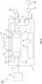
- an integrated circuit for energy harvesting is provided and an example of a system for energy harvesting 100 comprising such an integrated circuit 1 is shown on Fig.3 .
- the method of energy harvesting discussed above comprising steps of charging a first and a second rechargeable storage device and steps of transferring charges from the second to the first rechargeable storage device, can be applied in an automated and controlled way.
- the integrated circuit for energy harvesting has to be construed as a microchip comprising integrated circuits and a number of input and output pins, also named terminals.
- the microchip can have for example between 16 and 32 terminals.
- the microchip has a compact packaging resulting in a square or rectangular footprint with sides having a length between 1 and 5 mm.
- the integrated circuit 1 for energy harvesting comprises a first terminal 11 connectable with an energy harvester 70, a second terminal 12 connectable with a first rechargeable storage device 50 and a third terminal 13 connectable with a second rechargeable storage device 60.
- the integrated circuit further comprises a voltage converter system 20 suitable for converting input power into output power for charging at least two storage devices, a controller 40 for controlling the voltage converter system 20 and a monitoring unit 45 coupled with the controller 40 and configured for monitoring a parameter V Batt1 and a parameter V Batt2 .
- the parameters V Batt1 and V Batt2 are indicative of a charging level of respectively the first rechargeable storage device and the second rechargeable storage device when connected to respectively the second 12 and the third terminal 13.
- the parameter V Batt1 and the parameter V Batt2 correspond to a voltage sensed at respectively the second 12 and the third 13 terminal. In other embodiments, the parameters V Batt1 and V Batt2 correspond to an amount of charge counted by a charge counter during the charging process of respectively the first and second rechargeable storage devices.
- the integrated circuit 1 comprises a plurality of power input paths 31a,31b for transferring input power from an energy source to the voltage converter system and a plurality of power output paths 32a,32b for transferring output power from the voltage converter system to the output terminals of the integrated circuit.
- These input and output power paths have to be construed as electrical conductors.
- the voltage converter system when in operation, only uses one power path to receive input power and one output path to output the power. Therefore, the voltage converter system 20 comprises an input selection circuit 31 for selecting one power input path from the plurality of power input paths so as to receive an input power via the power input path selected.
- the voltage converter further comprises an output selection circuit 32 for selecting one power output path from the plurality of power output paths so as to output an output power via the output path selected.
- the integrated circuit 1 comprises at least a first power input path 31a configured for transferring input power from the first terminal 11 to the voltage converter system 20, and a second power input path 31b for transferring input power from the third terminal 13 to the voltage converter system 20.
- the integrated circuit further comprises at least a first power output path 32a for transferring output power from the voltage converter system 20 to the second terminal 12, and a second power output path 32b for transferring output power from the voltage converter system to the third terminal 13.
- the controller 40 is configured to form and switch between a number of specific combinations of power input and power output paths based on a comparison of the parameter V Batt1 with first predefined thresholds values and/or a comparison of the parameter V Batt2 with second predefined threshold values.
- the specific combinations the controller can form are: i) a first combination formed by selecting the first power input path 31a and selecting the first power output path 32a, ii) a second combination formed by selecting the first power input path 31a, and selecting the second power output path 32b and iii) a third combination formed by selecting the second power input path 31b and selecting the first power output path 32a.
- the controller not only can form one of these three specific input/output combinations but can also switch from one specific combination to another specific combination based on the comparison of the parameter V Batt1 and/or parameter V Batt2 with the predefined threshold values.
- the first predefined threshold values comprise for example the threshold values V Batt1-SW , V Batt1-low and V Batt1-up and the second predefined threshold values comprise for example the threshold values V Batt2-max and V Batt2-low discussed above.
- the first and second combination of selected power input/output paths as defined above correspond to a combination wherein the voltage converter system is transferring power from the energy harvester to respectively the first and second storage device.
- the third combination corresponds to the voltage converter system transferring power from the second to the first storage device.
- the method according to the invention discussed above also comprises a step of switching to the third combination of power input/output paths wherein energy is transferred from the second to the first storage device if V Batt1 drops below the critical threshold value V Batt1-SW .
- the condition of switching to the third combination of power input/output paths is only performed if the second storage device is charged which is determined, as discussed above, by comparing V Batt2 with a threshold value.
- the controller is performing the switching between the combinations of selected power/input paths based on the conditions and threshold values of the parameters V Batt1 and V Batt2 as discussed above.
- the controller is configured for switching from the first combination to the second combination if the parameter V Batt1 becomes equal or larger than an upper threshold value V Batt1-up and if the parameter V Batt2 is lower than an upper threshold value V Batt2-max , switching from the second combination to the first combination if the parameter V Batt1 has decreased from the upper threshold value V Batt1-up down to a lower threshold value V Batt1-low , with V Batt1-low ⁇ V Batt1-up , switching from the first combination to the third combination if the parameter V Batt1 has decreased from the lower threshold value V Batt1-low down to a critical threshold value V Batt1-SW , with V Batt1-SW ⁇ V Batt1-low , and if V Batt2 is above a lower threshold value V Batt2-low , with V Batt2-low
- the monitoring unit 45 comprises a signal comparator for comparing the parameters V Batt1 and V Batt2 with predefined threshold values.
- the parameters V Batt1 and V Batt2 correspond for example to a voltage resulting from a voltage measurement, an amount of charge resulting from a charge counter or a detection of any other quantity that is representative for a charging status of a rechargeable energy storage device.
- the signal comparator can either be an analogue signal comparator or a digital signal comparator, known in the art.
- the generally analogue signals V Batt1 and V Batt2 are first digitized using an ADC (analog to digital converter).
- the predefined threshold values can be values locally memorized by the controller, or the predefined threshold values can be generated by a reference voltage generator, or a voltage configurator external to the PMIC can be used and threshold values can be transmitted through a configuration terminal or connector.
- the voltage converter system 20 comprises one or more voltage converters and a voltage converter is for example a boost voltage converter, a buck voltage converter or a buck-boost voltage converter.
- a voltage converter is for example a boost voltage converter, a buck voltage converter or a buck-boost voltage converter.
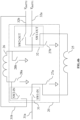
- Fig.4a and Fig.5 examples of embodiments of a voltage converter system 20 are shown comprising a single voltage converter for converting input power received via the selected power input path into output power outputted via the selected power output path.
- Fig.4b Fig.6a and Fig.6b examples of a voltage converter system 20 comprising two voltage converters are shown and in Fig.7 and Fig.8 , examples of voltage converter systems comprising three voltage converters are shown.
- controller has to be construed in the broadest sense as being an electronic digital circuit generally comprising combinatory logic.
- the controller controlling the voltage converter system is configured for controlling for example switches of one or more voltage converters and for controlling the switches of the input and output selection circuit.
- FIG.4a An embodiment of a voltage converter system comprising a single voltage converter for converting input power, received via the selected power input path, into output power outputted via the selected power output path, is schematically illustrated on Fig.4a , and Fig.5 .
- the single voltage converter shown makes use of an inductor 25 which is generally located outside the integrated circuit and which can be coupled to the integrated circuit with for example two dedicated terminals 14, 15 or by any other suitable coupling means. The operation of the voltage converter and the selection of the input and output paths will be further discussed.
- the input selection circuit 31 comprises a first input switch SW1-IN for enabling and disabling a current flow in the first power input path 31a, a second input switch SW2-IN for enabling and disabling a current flow in the second power input path 31b, a first output switch SW1-OUT for enabling and disabling a current flow in the first power output path 32a and a second output switch SW2-OUT for enabling and disabling a current flow in the second power output path 32b.
- selecting "a" power output path from the plurality of power output paths so as to output an output power via the power output path selected has to be construed as selecting "one" power output path from the plurality of power output paths.
- the first input path 31a and the first output path 32a are to be selected and hence the other input and output paths are to be de-selected and remain de-selected during the charging of the first storage device 50.
- the second input path 31b and the second output path 32b are for example de-selected by opening respectively switches SW2-IN and SW2-OUT. These switches are shown on Fig.4a .
- the first input path 31a and the second output path 32b are to be selected and the other input and output paths are to be de-selected and remain de-selected during the charging of the second rechargeable storage device.
- the second input path 31b and the first output path 32a are for example de-selected by opening respectively switches SW2-IN and SW1-OUT.
- the second input path 31b and the first output path 32a are to be selected and the other input and output paths are to be de-selected and maintained de-selected during the charge transfer from the second to the first rechargeable storage device.
- the first input path 31a and the second output path 32b are for example de-selected by opening respectively switches SW1-IN and SW2-OUT.
- the voltage converter 20 is a DC-DC buck/boost voltage converter as illustrated on Fig. 4a that is capable of operating in either a boost mode or a buck mode.
- the buck/boost voltage converter When the voltage converter input voltage is smaller than the voltage converter output voltage, the buck/boost voltage converter will operate in a boost mode.
- the buck/boost voltage converter will operate in a buck mode if the input voltage is higher than the output voltage. For example, when the first input path 31a and the first output path 32a are selected the input and output voltages for determining the operation mode correspond to respectively the voltage at the first terminal 11 and the voltage at the second terminal 12.
- the switch SW1-IN is maintained closed and the switch 27a remains open during the charging of the first storage device.
- the boost mode starts with a magnetic energy charging phase of the inductor 25 wherein the switch 27b is closed and the switch SW1-OUT is open, followed by a magnetic energy de-charging phase wherein the switch 27b is opened and the switch SW1-OUT is closed.
- the switches 27b and SW1-OUT power is transferred in a boost mode from the first terminal 11, i.e. where the energy harvester is connected, to the second terminal 12, where the first rechargeable storage device is connected.
- the switch SW1-OUT is maintained closed and the switch 27b remains open during the charging of the first storage device.
- the buck mode starts with a magnetic energy charging phase of the inductor 25 wherein the switch 27a is open and the switch SW1-IN is closed, followed by a magnetic energy de-charging phase wherein the switch 27a is closed and the switch SW1-IN is opened.
- the switches 27a and SW1-IN power is transferred in a buck mode from the first terminal 11, i.e. where the energy harvester is connected, to the second terminal 12, where the first rechargeable storage device is connected.
- the second storage device 60 connected to the third terminal 13 of the integrated circuit can start to be charged with energy from the energy harvester. Therefore, the first output path 32a is de-selected by opening switch SW1-OUT and by maintaining this switch open during the charging of the second rechargeable storage device.
- the voltage converter will also operate in a buck or a boost mode.
- the switch SW1-IN is maintained closed and the switch 27a remains open.
- the boost mode starts with a magnetic energy charging phase of the inductor wherein the switch 27b is closed and the switch SW2-OUT is open, followed by a magnetic energy de-charging phase wherein the switch 27b is opened and the switch SW2-OUT is closed. This cycle of magnetically charging and de-charging the inductor is cyclically repeated.
- the switch SW2-OUT is maintained closed and the switch 27b remains open.
- the buck mode starts with a charging phase of the inductor 25 wherein the switch 27a is open and the switch SW1-IN is closed, followed by a de-charging phase wherein the switch 27a is closed and the switch SW1-IN is opened. This cycle of magnetically charging and de-charging the inductor is cyclically repeated.
- switches shown on Fig.4a i.e. switches with references 27a, 27b, SW1-IN, SW2-IN, SW1-OUT and SW2-OUT, have to be construed as electronic switches configured for opening or closing an electrical conducting path or conductor. These switches are for example analogue electronic switches known in the art. These switches make use of for example MOS transistors. With the exemplary embodiment shown on Fig.4a , the number of electronic switches of the integrated circuit is limited as some of these switches are not only used as the standard switches needed for operating the DC/DC voltage converter but are also forming the switches for the input and output path selection circuit.
- the energy converter system 20 is not limited to a specific number of voltage converters.
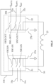
- Fig.4b an example of voltage converter system 20 is shown comprising two buck/boost voltage converters and wherein the voltage converter system comprises a plurality of switches with references 27a, 27b, 28a, 28b, SW1-IN, SW2-IN, SW1-OUT and SW2-OUT.
- the switches 27a, 27b, SW1-IN, SW1-OUT and SW2-OUT are used for operating a first buck/boost voltage converter for transferring power from the energy harvester to either a first rechargeable storage device at a voltage V Batt1 or to a second rechargeable storage device at a voltage V Batt2 .
- the switches 28a, 28b, SW2-IN, SW1-OUT are used for operating a second buck/boost voltage converter for transferring power from a second rechargeable storage device at a voltage V Batt2 to a first rechargeable storage device at a voltage V Batt1 .
- the switches SW1-IN, SW2-IN, SW1-OUT and SW2-OUT are not only used for the nominal operation of the buck/boost voltage converters but these switches are also forming part of an input selection circuit 31 and an output selection circuit 32 for selecting an input power path and an output power path as schematically illustrated on Fig.4b .
- each of the buck/boost voltage converters makes use of a dedicated inductor 25, 26.
- additional dedicated switches are used for forming the input and/or output selection circuit.
- additional dedicated switches are used for forming the input and/or output selection circuit.
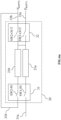
- Fig.6a an example of an embodiment of a voltage converter system 20 is shown comprising, besides the input 31 an output 32 selection circuits, two voltage converters 21a and 21b. As further illustrated on Fig.6a , there are in this example two power input paths 31a and 31b and two power output paths 32a and 32b.
- the first voltage converter 21a is used for converting input power received via the first power input path 31a into output power outputted via the first 32a or via the second 32b power output path, depending on what power output path is selected by the output selection circuit 32.
- the second voltage converter 21b is used for converting input power received via the second power input path 31b into output power outputted via the first power output path 32a.
- the two voltage converters can make use of one or two inductors (not shown on Fig. 6a ).
- the two voltage converters 21a, 21b do not necessarily have to be of the same type, for example, the first voltage converter 21a can be a buck-boost voltage converter and the second voltage converter 21b can be a buck voltage converter or a boost voltage converter.
- Fig.6b an alternative embodiment is shown that can perform the same functionalities as the embodiment shown on Fig.6a , but wherein the output selection circuit 32 makes use of three switches SW1-OUT, SW2-OUT and SW3-OUT instead of two output switches.
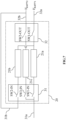
- Fig. 7 an example of an embodiment of a voltage converter system 20 comprising three voltage converters 21a, 21b, 21c is shown.
- the first voltage converter 21a is converting input power received via the first power input path 31a into output power outputted via the first power output path 32a.
- the second voltage converter 21b is converting input power received via the second power input path 31b into output power outputted via the first power output path 32a.
- the third voltage converter 21c is converting input power received via the first power input path 31a into output power outputted to the second power output path 32b.
- the three voltage converters can make use of one, two or three inductors (not shown on Fig.7 ).
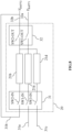
- Fig. 8 an example is shown where the input selection circuit 31 can select from three power input paths 31a, 31b and 31c.
- the voltage converter system 20 shown comprises three voltage converters 21a, 21b and 21d.
- the functionality of the first 21a and second 21b voltage converter in this example is the same as for the example shown on Fig.6a and discussed above.
- the third voltage converter 21d is used for converting input power received via the third power input path 31c into output power outputted via the first 32a power output path.
- the person skilled in the art can specify other embodiments of voltage converter systems 20 than the ones described above and shown on Fig.4a to Fig.8 .
- What the embodiments of voltage converter systems according to the invention have in common is that they comprise an input selection circuit 31 for selecting a power input path from a plurality of power input paths so as to receive an input power via the power input path selected and an output selection circuit 32 for selecting a power output path from the plurality of power output paths so as to output an output power via the power output path selected.
- the switches used to select a power input path or to select a power output path correspond to the power switches of the DC/DC voltage converter used for the nominal operation of the DC/DC voltage converter. In this way, the total number of switches needed for the voltage converter system can be limited.
- the controller 40 is configured for performing a step A) of selecting the first input path 31a and repetitively performing the following sub-steps A1) to A4): A1) selecting the first output path 32a, A2) operating the voltage converter 20 for converting input power received via the first power input path 31a into output power outputted via the first power output path, A3) if V Batt1 becomes equal or larger than an upper threshold value V Batt1-up then de-selecting the first output path 32a, and A4) if V Batt2 is lower than an upper threshold value V Batt2-max then
- the controller 40 is maintaining the parameter V Batt1 between the threshold values V Batt1-low and V Batt1-up .
- the controller 40 is further configured for performing a step B) if V Batt1 has decreased from the lower threshold value V Batt1-low down to a critical threshold value V Batt1-SW , with V Batt1-SW ⁇ V Batt1-low , and if V Batt2 is above a lower threshold value V Batt2-low , with V Batt2-low ⁇ V Batt2-max .
- the step B) is composed of the following sub-steps: B1) selecting the second input path 31b, B2) selecting the first output path 32a, and B3) operating the voltage converter 20 for converting input power received via the second power input path 31b into output power outputted via the first power output path 32a.
- the controller avoids the first rechargeable storage device from being fully de-charged when the energy harvester is not operating. At the same time the application load coupled to the first rechargeable storage device can continue to operate even if the energy harvester has stopped operating.
- the controller is configured, when performing sub-step A4) discussed above, for additionally performing a step iv) if V Batt2 has reached the upper threshold value V Batt2-max .
- the additional step step iv) comprises performing one of the following steps: i) de-selecting the second power output path 32b and/or de-selecting the first power input path 31a, ii) stop operating the voltage converter system 20, iii) selecting the first input path 31a and selecting the first output path 32a.
- step A4) when in step A4) iv) the option iii) of selecting the first input path 31a and selecting the first output path 32a, is applied, then the energy harvester is again continuing charging the first rechargeable storage device with energy from the energy harvester. If the threshold V Batt1-up is not a maximum charging level for the first rechargeable storage device and if a maximum charging level V Batt1-max exists with V Batt1-max > V Batt1-up , then in this situation where the second rechargeable storage device is fully charged, the first rechargeable storage device can be continued to be charged to the maximum charging level of V Batt1-max .
- the controller when performing step B mentioned above, is configured to additionally perform a sub-step B4), namely if the voltage V Batt1 becomes equal or larger than the upper threshold value V Batt1-up then performing at least one of the following steps: i) de-selecting the first power output path 32a and/or de-selecting the second power input path 31b, ii) selecting the first input path 31a and selecting the second output path 32b, iii) stop operating the voltage converter 20.
- the step ii) when the step i) is applied, then the energy harvester will, when operational, continue to charge the second rechargeable storage device.
- V Batt1 drops below V Batt1-SW then power will again be transferred from the second to the first rechargeable storage device.
- V Batt1-SW power will again be transferred from the second to the first rechargeable storage device.
- V Batt1-low power is transferred from the energy harvester to the first rechargeable storage device and V Batt1 is increasing again until V Batt1 has reached the upper threshold V Batt1-up .
- the monitoring unit 45 is configured to monitor a parameter V H that indicates if the energy harvester connected to the first terminal is operational or not.
- this parameter could be a voltage measured at the first input terminal.
- the controller can decide when to re-select the first power input path for receiving power from the energy harvester and charging the first rechargeable storage device with charges from the energy harvester instead of charging the first rechargeable storage device with charges from the second rechargeable storage device.
- the integrated circuit 1 for energy harvesting according to the present invention is not limited to the number of power input paths and the number of power output paths.
- Fig. 5 an integrated circuit 1 with a voltage converter is shown having an input selection circuit 31 configured to select between three power input paths 31a, 31b and 31c and having an output selection circuit 32 configured to select between three power output paths 32a, 32b and 32c.
- the input selection circuit 31 and the output selection circuit 32 have respectively additional switches SW3-IN and SW3-OUT.
- a third power input path 31c is used for transferring input power from a fourth terminal to the voltage converter system 20.
- the fourth terminal is connectable with an auxiliary energy source, such as for example a primary battery.
- the controller 40 is configured for performing steps of C1) selecting the third power input path 31c, C2) selecting the first power output path 32a and C3) operating the voltage converter 20 for converting input power received via the third power input path 31c into output power outputted via the first power output path 32a.
- an auxiliary power source coupled to the fourth terminal can be used to charge the first rechargeable storage device.
- a third power output path 32c is coupling the voltage converter system with a fifth terminal connectable with for example an auxiliary rechargeable storage device being at a voltage V AUX . In this way, when the first and the second rechargeable storage device are fully charged, the third rechargeable storage device can be charged.
Landscapes
- Engineering & Computer Science (AREA)
- Power Engineering (AREA)
- Computer Networks & Wireless Communication (AREA)
- Charge And Discharge Circuits For Batteries Or The Like (AREA)
- Secondary Cells (AREA)
Claims (18)
- Verfahren zur Energiegewinnung unter Verwendung eines Spannungswandlersystems (20) zum Umwandeln von Eingangsleistung in Ausgangsleistung und zum Laden mindestens einer ersten (50) und einer zweiten (60) wiederaufladbaren Speichervorrichtung, wobei das Verfahren folgende Schritte umfasst:• Koppeln eines ersten Leistungseingangspfads (31a) zwischen eine Energiegewinnungseinrichtung (70) und das Spannungswandlersystem (20) zum Übertragen von Eingangsleistung von der Energiegewinnungseinrichtung (70) zu dem Leistungswandlersystem,• Überwachen eines Parameters VBatt1 und eines Parameters VBatt2, die einen Ladestand der ersten wiederaufladbaren Speichervorrichtung (50) bzw. der zweiten wiederaufladbaren Speichervorrichtung (60) angeben,• Koppeln der ersten wiederaufladbaren Speichervorrichtung (50) mit einer Anwendungslast (90), sodass die erste wiederaufladbare Speichervorrichtung, wenn sie geladen ist, die Anwendungslast (90) mit Leistung versorgen kann,• Koordinieren des Ladens der ersten (50) und der zweiten (60) wiederaufladbaren Speichervorrichtung durch wiederholtes Durchführen der folgenden Unterschritte:1a) Koppeln eines ersten Leistungsausgangspfads (32a) zwischen das Spannungswandlersystem (20) und die erste wiederaufladbare Speichervorrichtung (50) zum Übertragen von Ausgangsleistung von dem Spannungswandler System zu der ersten wiederaufladbaren Speichervorrichtung (50),2a) Betreiben des Spannungswandlersystems (20) zum Übertragen von Ladungen von der Energiegewinnungseinrichtung (70) zu der ersten wiederaufladbaren Speichervorrichtung (50), um die erste wiederaufladbare Speichervorrichtung (50) mit Energie von der Energiegewinnungseinrichtung (70) zu laden, und Betreiben des Spannungswandlersystems zum Laden der ersten wiederaufladbaren Speichervorrichtung, bis der Parameter VBatt1 einen oberen Schwellenwert VBatt1-up erreicht hat,3a) wenn VBatt1 den oberen Schwellenwert VBatt1-up erreicht hat und VBatt2 unter einem oberen Schwellenwert VBatt2-max liegt, danni) Entkoppeln des ersten Leistungsausgangspfads (32a) und Koppeln eines zweiten Leistungsausgangspfads (32b) zwischen das Spannungswandlersystem (20) und die zweite wiederaufladbare Speichervorrichtung (60) zum Übertragen von Ausgangsleistung von dem Spannungswandlersystem zu der zweiten wiederaufladbaren Speichervorrichtung (60), undii) Betreiben des Spannungswandlersystems (20) zum Übertragen von Ladungen von der Energiegewinnungsvorrichtung (70) zu der ersten wiederaufladbaren Speichervorrichtung (50), um die zweite wiederaufladbare Speichervorrichtung (60) mit Energie von der Energiegewinnungseinrichtung (70) zu laden,4a) wenn der Parameter VBatt1 während des Ladens der zweiten (60) wiederaufladbaren Speichervorrichtung anschließend von dem oberen Schwellenwert VBatt1-up auf einen unteren Schwellenwert VBatt1-low abgenommen hat, wobei VBatt1-low < VBatt1-up gilt, dann Entkoppeln des zweiten Leistungsausgangspfads (32b) und erneutes Beginnen bei Schritt 1a),• Übertragen von Energie von der zweiten wiederaufladbaren Speichervorrichtung (60) zu der ersten wiederaufladbaren Speichervorrichtung (50), wenn i) der Parameter VBatt1 der ersten wiederaufladbaren Speichervorrichtung (50) unter einen kritischen Schwellenwert VBatt1-SW abgefallen ist, wobei VBatt1-SW < VBatt1-low gilt, und wenn ii) der Parameter VBatt2 gleich oder größer als ein vordefinierter Schwellenwert VBatt2-low ist, wobei das Übertragen von Energie die folgenden Unterschritte umfasst:1b) Entkoppeln des ersten Leistungseingangspfads (31a), 2b) Koppeln eines zweiten Leistungseingangspfads (31b) zwischen die zweite wiederaufladbare Speichervorrichtung (60) und das Spannungswandlersystem (20) zum Übertragen von Eingangsleistung von der zweiten wiederaufladbaren Speichervorrichtung (60) an das Spannungswandlersystem (20) und3b) Betreiben des Spannungswandlersystems (20) zum Laden der ersten wiederaufladbaren Speichervorrichtung (50) mit Energie von der zweiten wiederaufladbaren Speichervorrichtung (60), bis der Parameter VBatt1 der ersten wiederaufladbaren Speichervorrichtung (50) den oberen Schwellenwert VBatt1-up erreicht hat.
- Verfahren nach Anspruch 1, wobei die zweite wiederaufladbare Speichervorrichtung (60) eine Energiespeicherkapazität aufweist, die mehr als das Fünffache, vorzugsweise mehr als das Zehnfache, der Energiespeicherkapazität der ersten wiederaufladbaren Speichervorrichtung (50) beträgt.
- Verfahren nach einem der vorhergehenden Ansprüche, wobei der Schritt des Koordinierens des Ladens der ersten (50) und der zweiten (60) wiederaufladbaren Speichervorrichtung einen folgenden Unterschritt umfasst:
3a) iii) wenn VBatt2 den oberen Schwellenwert VBatt2-max erreicht hat, dann Durchführen mindestens eines der folgenden Schritte:a) Entkoppeln des zweiten Leistungsausgangspfads (32b) und/oder Entkoppeln des ersten Leistungseingangspfads (31a),b) Stoppen des Betriebs des Spannungswandlersystems (20),c) Koppeln des ersten Leistungseingangspfads (31a) und Koppeln des ersten Leistungsausgangspfad (32b). - Verfahren nach einem der vorhergehenden Ansprüche, wobei das Übertragen von Energie von der zweiten wiederaufladbaren Speichervorrichtung (60) zu der ersten wiederaufladbaren Speichervorrichtung (50) einen folgenden weiteren Unterschritt umfasst:
4b) wenn der Parameter VBatt1 den oberen Schwellenwert VBatt1-up erreicht hat, dann Durchführen eines oder einer Kombination der folgenden Schritte:i) Entkoppeln des ersten Leistungsausgangspfads (32a) und/oder Entkoppeln des zweiten Leistungseingangspfads (31b), ii) Koppeln des ersten Leistungseingangspfads (31a) und Koppeln des zweiten Leistungsausgangspfads (32b), iii) Stoppen des Betriebs des Spannungswandlersystems (20). - Verfahren nach einem der vorhergehenden Ansprüche, das einen folgenden Schritt umfasst:• wenn der Parameter VBatt1 unter den kritischen Schwellenwert VBatt1-SW abgefallen ist und wenn die zweite wiederaufladbare Speichervorrichtung (60) nicht geladen ist, dann Entkoppeln des ersten Leistungseingangspfads (31a) und Koppeln eines dritten Leistungseingangspfads (31c) zwischen eine Hilfsenergiequelle, wie etwa eine Primärbatterie, und das Leistungswandlersystem zum Übertragen von Eingangsleistung von der Hilfsenergiequelle zu dem Spannungswandlersystem (20) und Betreiben des Spannungswandlersystems (20) zum Laden der ersten wiederaufladbaren Speichervorrichtung (50) mit Energie von der Hilfsenergiequelle, bis der Parameter VBatt1 der ersten Speichervorrichtung (50) den oberen Schwellenwert VBatt1-up erreicht hat.
- Verfahren nach einem der vorhergehenden Ansprüche, das einen folgenden Schritt umfasst:• Vorladen der zweiten wiederaufladbaren Speichervorrichtung (60) durch Durchführen der folgenden Schritte: i) Koppeln des zweiten Leistungsausgangspfads (32b) zwischen das Spannungswandlersystem (20) und die zweite wiederaufladbare Speichervorrichtung (60) zum Übertragen von Ausgangsleistung von dem Spannungswandlersystem zu der zweiten wiederaufladbaren Speichervorrichtung (60), ii) Betreiben des Spannungswandlersystems (20) zum Laden der zweiten wiederaufladbaren Speichervorrichtung (60) mit Energie von der Energiegewinnungseinrichtung (70), bis der Parameter VBatt2 einen vordefinierten Schwellenwert VBatt2-PC erreicht hat, wobei VBatt2-PC ≥ VBatt2-low gilt, und wobei der Schritt des Vorladens durchgeführt wird, bevor der Schritt des Koordinierens des Ladens der ersten (50) und der zweiten (60) wiederaufladbaren Speichervorrichtung durchgeführt wird.
- Verfahren nach einem der vorhergehenden Ansprüche, wobei das Spannungswandlersystem (20) einen Spannungswandler umfasst, ausgelegt zum Umwandeln von über den gekoppelten Leistungseingangspfad (31a, 31b, 31c) empfangener Eingangsleistung in über den gekoppelten Leistungsausgangspfad (32a, 32b, 32c) ausgegebene Ausgangsleistung, und wobei es sich bei dem Spannungswandler um einen Aufwärtsspannungswandler oder einen Abwärtsspannungswandler oder ein Abwärts-Aufwärtsspannungswandler handelt.
- Integrierte Schaltung (1) zur Energiegewinnung, die Folgendes umfasst:• einen Spannungswandlersystem (20), das sich zur Umwandlung von Eingangsleistung in Ausgangsleistung eignet und das sich zum Laden von mindestens zwei wiederaufladbaren Speichervorrichtungen eignet,• einen ersten Anschluss (11), der mit einer Energiegewinnungseinrichtung (70) verbunden werden kann,• einen zweiten Anschluss (12), der mit einer ersten wiederaufladbaren Speichervorrichtung (50) verbunden werden kann,• einen dritten Anschluss (13), der mit einer zweiten wiederaufladbaren Speichervorrichtung (60) verbunden werden kann,• eine Steuerung (40) zum Steuern des Spannungswandlersystems (20),• mehrere Leistungseingangspfade, umfassend mindestens einen ersten Leistungseingangspfad (31a) zum Übertragen von Eingangsleistung von dem ersten Anschluss (11) zu dem Spannungswandlersystem (20),• mehrere Leistungsausgangspfade, umfassend mindestens einen ersten Leistungsausgangspfad (32a) zum Übertragen von Ausgangsleistung von dem Spannungswandlersystem (20) zu dem zweiten Anschluss (12) und einen zweiten Leistungsausgangspfad (32b) zum Übertragen von Ausgangsleistung von dem Spannungswandlersystem zu dem dritten Anschluss (13),• eine Übertragungseinheit (45), die mit der Steuerung (40) gekoppelt ist und ausgelegt ist zum Überwachen eines Parameters VBatt1 und eines Parameters VBatt2, die einen Ladestand der ersten wiederaufladbaren Speichervorrichtung (50) bzw. der zweiten wiederaufladbaren Speichervorrichtung (60) angeben, wenn sie mit dem zweiten (12) bzw. dem dritten Anschluss (13) verbunden sind,dadurch gekennzeichnet, dass die mehreren Leistungseingangspfade einen zweiten Leistungseingangspfad (31b) zum Übertragen von Eingangsleistung von dem dritten Anschluss (13) zu dem Spannungswandlersystem (20) umfassen,und dadurch, dass das Spannungswandlersystem (20) eine Eingangsauswahlschaltung (31), ausgelegt zum Auswählen eines Leitungseingangspfads aus den mehreren Leistungseingangspfaden, um eine Eingangsleistung über den ausgewählten Leistungseingangspfad zu empfangen, und eine Ausgangsauswahlschaltung (32), ausgelegt zum Auswählen eines Leistungsausgangspfads aus den mehreren Leistungsausgangspfaden, um eine Ausgangsleistung über den ausgewählten Leistungsausgangspfad auszugeben, umfasst,und dadurch, dass die Steuerung (40) ausgelegt ist zum Bilden und Umschalten zwischen einer Anzahl spezifischer Kombinationen eines Leistungseingangs- und eines Leistungsausgangspfads basierend auf einem Vergleich des Parameters VBatt1 mit ersten vordefinierten Schwellenwerten und/oder einem Vergleich des Parameters VBatt2 mit zweiten vordefinierten Schwellenwerten, und wobei die spezifischen Kombinationen Folgendes umfassen:i) eine erste Kombination, gebildet durch Auswählen des ersten Leistungseingangspfads (31a) und Auswählen des ersten Leistungsausgangspfads (32a),ii) eine zweite Kombination, gebildet durch Auswählen des ersten Leistungseingangspfads (31a) und Auswählen des zweiten Leistungsausgangspfads (32b),iii) eine dritte Kombination, gebildet durch Auswählen des zweiten Leistungseingangspfads (31b) und Auswählen des ersten Leistungsausgangspfads (32a).
- Integrierte Schaltung (1) nach Anspruch 8, wobei die Steuerung (40) dazu ausgelegt ist, Folgendes durchzuführen:A. Auswählen des ersten Leistungseingangspfads (31a) und wiederholtes Durchführen der folgenden Unterschritte:A1) Auswählen des ersten Leistungsausgangspfads (32a), A2) Betreiben des Spannungswandlersystems (20) zum Umwandeln von über den ersten Leistungseingangspfad (31a) empfangener Eingangsleistung in über den ersten Leistungsausgangspfad (32a) ausgegebene Ausgangsleistung,A3) wenn VBatt1 gleich oder größer als ein oberer Schwellenwert VBatt1-up wird, dann Deselektieren des ersten Leistungsausgangspfads (32a),A4) wenn VBatt2 niedriger als ein oberer Schwellenwert VBatt2-max ist, danni) Auswählen des zweiten Leistungsausgangspfads (32b),ii) Betreiben des Spannungswandlersystems (20) zum Umwandeln von über den ersten Leistungseingangspfad (31a) empfangener Eingangsleistung in über den zweiten Leistungsausgangspfad (32b) ausgegebene Ausgangsleistung, undiii) wenn VBatt1 anschließend von dem oberen Schwellenwert VBatt1-up auf einen unteren Schwellenwert VBatt1-low abgenommen hat, wobei VBatt1-low < VBatt1-up gilt, dann Deselektieren des zweiten Leistungsausgangspfads (32b) und erneutes Beginnen bei Schritt A1),B. wenn VBatt1 von dem unteren Schwellenwert VBatt1-low auf einen kritischen Schwellenwert VBatt1-SW abgefallen ist, wobei VBatt1-SW < VBatt1-low gilt, und wenn VBatt2 über einemunteren Schwellenwert VBatt2-low liegt, wobei VBatt2-low < VBatt2-max gilt, dann Durchführen der folgenden Unterschritte:B1) Auswählen des zweiten Leistungsausgangspfads (31b), B2) Auswählen des ersten Leistungsausgangspfads (32a) undB3) Betreiben des Spannungswandlersystems (20) zum Umwandeln von über den zweiten Leistungseingangspfad (31b) empfangener Eingangsleistung in über den ersten Leistungsausgangspfad (32a) ausgegebene Ausgangsleistung.
- Integrierte Schaltung (1) nach Anspruch 9, wobei der Unterschritt A4) einen folgenden weiteren Schritt umfasst:
A4) iv) wenn VBatt2 den oberen Schwellenwert VBatt2-max erreicht hat, dann Durchführen mindestens eines der folgenden Schritte: i) Deselektieren des zweiten Leistungsausgangspfads (32b) und/oder Deselektieren des ersten Leistungseingangspfads (31a), ii) Stoppen des Betriebs des Spannungswandlersystems (20), iii) Auswählen des ersten Leistungseingangspfads (31a) und Auswählen des ersten Leistungsausgangspfads (32a). - Integrierte Schaltung (1) nach Anspruch 9 oder 10, wobei die Steuerung dazu ausgelegt ist, einen folgenden weiteren Unterschritt durchzuführen:
B4) wenn die Spannung VBatt1 gleich oder größer als der obere Schwellenwert VBatt1-up wird, dann Durchführen mindestens eines der Folgenden: i) Deselektieren des ersten Leistungsausgangspfads (32a) und/oder Deselektieren des zweiten Leistungseingangspfads (31b), ii) Auswählen des ersten Leistungseingangspfads (31a) und Auswählen des zweiten Leistungsausgangspfads (32b), iii) Stoppen des Betriebs des Spannungswandlersystems (20). - Integrierte Schaltung (1) nach Anspruch 8, wobei die Steuerung (40) ferner zu Folgendem ausgelegt ist:• Umschalten von der ersten Kombination auf die zweite Kombination, wenn der Parameter VBatt1 gleich oder größer als ein oberer Schwellenwert VBatt1-up wird und wenn der Parameter VBatt2 niedriger als ein oberer Schwellenwert VBatt2-max ist,• Umschalten von der zweiten Kombination auf die erste Kombination, wenn der Parameter VBatt1 von dem oberen Schwellenwert VBatt1-up auf einen unteren Schwellenwert VBatt1-low abgenommen hat, wobei VBatt1-low < VBatt1-up gilt, und• Umschalten von der ersten Kombination auf die zweite Kombination, wenn der Parameter VBatt1 von dem unteren Schwellenwert VBatt1-low auf einen kritischen Schwellenwert VBatt1-SW abgenommen hat, wobei VBatt1-SW < VBatt1-low gilt, und wenn VBatt2 über einem unteren Schwellenwert VBatt2-low liegt, wobei VBatt2-low < VBatt2-max gilt.
- Integrierte Schaltung (1) nach einem der Ansprüche 8 bis 12, wobei die Eingangsauswahlschaltung (31) einen ersten Eingangsschalter (SW1-IN) zum Freigeben und Sperren eines Stromflusses in dem ersten Leistungseingangspfad (31a), einen zweiten Eingangsschalter (SW2-IN) zum Freigeben und Sperren eines Stromflusses in dem zweiten Leistungseingangspfad (31b), einen ersten Ausgangsschalter (SW1-OUT) zum Freigeben und Sperren eines Stromflusses in den ersten Leistungsausgangspfad (32a) und einen zweiten Ausgangsschalter (SW2-OUT) zum Freigeben und Sperren eines Stromflusses in dem zweiten Leistungsausgangspfad (32b) umfasst.
- Integrierte Schaltung (1) nach einem der Ansprüche 8 bis 13, umfassend einen vierten Anschluss, der mit einer Hilfsenergiequelle, wie etwa eine Primärbatterie, verbunden werden kann, und wobei die mehreren Leistungseingangspfade einen dritten Eingangspfad (31c) zum Übertragen von Leistung von dem vierten Anschluss zu dem Spannungswandlersystem umfassen und wobei die spezifischen Kombinationen Folgendes umfassen:
iv) eine vierte Kombination, gebildet durch Auswählen des dritten Leistungseingangspfads (31c) und Auswählen des ersten Leistungsausgangspfads (32a). - Integrierte Schaltung (1) nach einem der Ansprüche 8 bis 14, wobei das Spannungswandlersystem (20) einen Spannungswandler zum Umwandeln von über den ausgewählten Leistungseingangspfad (31a, 31b, 31c) empfangener Eingangsleistung in über den ausgewählten Leistungsausgangspfad (32a, 32b, 32c) ausgegebene Ausgangsleistung umfasst und wobei es sich bei dem Spannungswandler um einen Aufwärtsspannungswandler oder einen Abwärtsspannungswandler oder ein Abwärts-Aufwärtsspannungswandler handelt.
- Integrierte Schaltung (1) nach einem der Ansprüche 8 bis 14, wobei das Spannungswandlersystem (20) Folgendes umfasst:• einen ersten Spannungswandler (21a) zum Umwandeln von über den ersten Leistungseingangspfad (31a) empfangener Eingangsleistung in über den ersten (32a) oder den zweiten (32b) Leistungsausgangspfad ausgegebene Ausgangsleistung,• einen zweiten Spannungswandler (21b) zum Umwandeln von über den zweiten Leistungseingangspfad (31b) empfangener Eingangsleistung in über den ersten Leistungsausgangspfad (32a) ausgegebene Ausgangsleistung.
- Integrierte Schaltung (1) nach einem der Ansprüche 8 bis 14, wobei das Spannungswandlersystem (20) Folgendes umfasst:• einen ersten Spannungswandler (21a) zum Umwandeln von über den ersten Leistungseingangspfad (31a) empfangener Eingangsleistung in über den ersten Leistungsausgangspfad (32a) ausgegebene Ausgangsleistung,• einen zweiten Spannungswandler (21b) zum Umwandeln von über den zweiten Leistungseingangspfad (31b) empfangener Eingangsleistung in über den ersten Leistungsausgangspfad (32a) ausgegebene Ausgangsleistung.• einen dritten Spannungswandler (21c) zum Umwandeln von über den ersten Leistungseingangspfad (31a) empfangener Eingangsleistung in über den zweiten Leistungsausgangspfad (32b) ausgegebene Ausgangsleistung.
- System zur Energiegewinnung, das Folgendes umfasst:• eine integrierte Schaltung (1) nach einem der Ansprüche 8 bis 17,• eine Energiegewinnungseinrichtung (70), die mit dem ersten Anschluss (11) gekoppelt ist,• eine erste wiederaufladbare Speichervorrichtung (50), die mit dem zweiten Anschluss (12) gekoppelt ist, wobei es sich bei der ersten wiederaufladbaren Speichervorrichtung vorzugsweise um eine wiederaufladbare Batterie, einen Kondensator oder ein Superkondensator handelt,• eine zweite wiederaufladbare Speichervorrichtung (60), die mit dem dritten Anschluss (13) gekoppelt ist, wobei es sich bei der zweiten wiederaufladbaren Speichervorrichtung vorzugsweise um eine wiederaufladbare Batterie, einen Kondensator oder ein Superkondensator handelt und wobei die zweite wiederaufladbare Speichervorrichtung (60) eine Energiespeicherkapazität aufweist, die mehr als das Fünffache, vorzugsweise mehr als das Zehnfache, der Energiespeicherkapazität der ersten wiederaufladbaren Speichervorrichtung (50) beträgt.
Applications Claiming Priority (2)
| Application Number | Priority Date | Filing Date | Title |
|---|---|---|---|
| EP19177470 | 2019-05-29 | ||
| PCT/EP2020/063935 WO2020239532A1 (en) | 2019-05-29 | 2020-05-19 | Method and device for energy harvesting and charging rechargeable energy storage devices |
Publications (3)
| Publication Number | Publication Date |
|---|---|
| EP3977589A1 EP3977589A1 (de) | 2022-04-06 |
| EP3977589C0 EP3977589C0 (de) | 2023-08-09 |
| EP3977589B1 true EP3977589B1 (de) | 2023-08-09 |
Family
ID=66677040
Family Applications (1)
| Application Number | Title | Priority Date | Filing Date |
|---|---|---|---|
| EP20725574.6A Active EP3977589B1 (de) | 2019-05-29 | 2020-05-19 | Verfahren und vorrichtung zur energiegewinnung und zum laden von wiederaufladbaren energiespeichervorrichtungen |
Country Status (6)
| Country | Link |
|---|---|
| US (1) | US12119663B2 (de) |
| EP (1) | EP3977589B1 (de) |
| JP (1) | JP7508126B2 (de) |
| KR (1) | KR102906675B1 (de) |
| CN (1) | CN113875122B (de) |
| WO (1) | WO2020239532A1 (de) |
Families Citing this family (2)
| Publication number | Priority date | Publication date | Assignee | Title |
|---|---|---|---|---|
| US12007799B2 (en) * | 2021-10-12 | 2024-06-11 | Everactive, Inc. | Energy operating systems and related techniques |
| GB202209891D0 (en) * | 2022-07-05 | 2022-08-17 | Lightricity Ltd | Ultra-low power energy harvesting electronic devices with energy efficient backup circuits |
Family Cites Families (13)
| Publication number | Priority date | Publication date | Assignee | Title |
|---|---|---|---|---|
| US8253389B2 (en) * | 2010-02-17 | 2012-08-28 | Texas Instruments Incorporated | Battery protection circuit and method for energy harvester circuit |
| JP5668132B1 (ja) * | 2013-12-27 | 2015-02-12 | 株式会社フジクラ | 蓄電システム、及び蓄電方法 |
| CN105850003B (zh) * | 2013-12-27 | 2018-06-29 | 株式会社藤仓 | 蓄电系统以及蓄电方法 |
| US20170070085A1 (en) * | 2014-03-03 | 2017-03-09 | Robert Bosch Gmbh | Hybrid storage system |
| EP3167536B1 (de) * | 2014-07-08 | 2018-04-25 | Lisini, Gianni | Verfahren und zugehörige vorrichtung zur übertragung von strom von einer stromquelle zu einer ladung mit elektrischem betrieb |
| WO2016196640A1 (en) | 2015-06-01 | 2016-12-08 | Tyco Fire & Security Gmbh | Adaptive power management for self-sustaining energy harvesting system |
| US9893527B2 (en) | 2014-12-18 | 2018-02-13 | Fujikura Ltd. | Power storage system and power storage method |
| JP5857119B1 (ja) * | 2014-12-18 | 2016-02-10 | 株式会社フジクラ | 蓄電システム、及び蓄電方法 |
| JP6145741B1 (ja) * | 2016-12-27 | 2017-06-14 | パナソニックIpマネジメント株式会社 | エナジーハーベスト端末 |
| EP3491714B1 (de) | 2017-06-22 | 2022-04-27 | e-peas S.A. | Integrierte leistungsverwaltungsschaltung zur energiegewinnung mit primärbatterieeingang |
| WO2018234485A1 (en) | 2017-06-22 | 2018-12-27 | E-Peas S.A. | Power management integrated circuit with optimum power point evaluation |
| US10625626B2 (en) * | 2017-11-29 | 2020-04-21 | Nio Usa, Inc. | Charging systems and methods for electric vehicles |
| CN114830488B (zh) * | 2019-12-10 | 2025-10-03 | 电子便携式能源自主系统股份公司 | 用于使用冷启动电压转换器进行能量采集的方法和设备 |
-
2020
- 2020-05-19 JP JP2021569346A patent/JP7508126B2/ja active Active
- 2020-05-19 KR KR1020217039258A patent/KR102906675B1/ko active Active
- 2020-05-19 CN CN202080038548.9A patent/CN113875122B/zh active Active
- 2020-05-19 WO PCT/EP2020/063935 patent/WO2020239532A1/en not_active Ceased
- 2020-05-19 US US17/611,963 patent/US12119663B2/en active Active
- 2020-05-19 EP EP20725574.6A patent/EP3977589B1/de active Active
Also Published As
| Publication number | Publication date |
|---|---|
| JP2022534033A (ja) | 2022-07-27 |
| WO2020239532A1 (en) | 2020-12-03 |
| EP3977589C0 (de) | 2023-08-09 |
| EP3977589A1 (de) | 2022-04-06 |
| CN113875122B (zh) | 2025-03-14 |
| KR20220015402A (ko) | 2022-02-08 |
| US12119663B2 (en) | 2024-10-15 |
| US20220239150A1 (en) | 2022-07-28 |
| KR102906675B1 (ko) | 2025-12-30 |
| CN113875122A (zh) | 2021-12-31 |
| JP7508126B2 (ja) | 2024-07-01 |
Similar Documents
| Publication | Publication Date | Title |
|---|---|---|
| US11277018B2 (en) | Power management integrated circuit for energy harvesting with primary battery input | |
| CN101192757B (zh) | 充电系统、充电装置以及电池组件 | |
| CN101960690B (zh) | 充电设备和充电方法 | |
| JP5363740B2 (ja) | 充電制御回路、電池パック、及び充電システム | |
| JP4691140B2 (ja) | 充放電システムおよび携帯式コンピュータ | |
| CN106469931A (zh) | 电池系统 | |
| JP2013520947A (ja) | バッテリセルコンバータ管理システム | |
| CN102195333A (zh) | 直流电源装置 | |
| CN103683373A (zh) | 电池平衡电路和使用其的电池平衡方法 | |
| CN109874366A (zh) | 电机和设备 | |
| EP3977589B1 (de) | Verfahren und vorrichtung zur energiegewinnung und zum laden von wiederaufladbaren energiespeichervorrichtungen | |
| EP3891860B1 (de) | Verfahren und vorrichtung zur energiegewinnung unter verwendung eines kaltstartspannungswandlers | |
| EP3769397B1 (de) | Verfahren und vorrichtung zum laden einer speichervorrichtung mit energie aus einem energiegewinner | |
| JP5165405B2 (ja) | 充電制御回路、電池パック、及び充電システム | |
| HK40060189A (en) | Method and device for energy harvesting and charging rechargeable energy storage devices | |
| HK40060189B (zh) | 能量采集和对可再充电能量储存设备充电的方法和设备 | |
| JP2004288537A (ja) | パック電池、二次電池充電装置および二次電池充電方法 | |
| CN109638901B (zh) | 电池训练设备 | |
| JP2002315225A (ja) | 電池パック及び該電池パックを電源とする外部ホスト機器システム | |
| US20070222412A1 (en) | Device and method for the automatic regulation of the charging of an electrochemical generator |
Legal Events
| Date | Code | Title | Description |
|---|---|---|---|
| STAA | Information on the status of an ep patent application or granted ep patent |
Free format text: STATUS: UNKNOWN |
|
| STAA | Information on the status of an ep patent application or granted ep patent |
Free format text: STATUS: THE INTERNATIONAL PUBLICATION HAS BEEN MADE |
|
| PUAI | Public reference made under article 153(3) epc to a published international application that has entered the european phase |
Free format text: ORIGINAL CODE: 0009012 |
|
| STAA | Information on the status of an ep patent application or granted ep patent |
Free format text: STATUS: REQUEST FOR EXAMINATION WAS MADE |
|
| 17P | Request for examination filed |
Effective date: 20211119 |
|
| AK | Designated contracting states |
Kind code of ref document: A1 Designated state(s): AL AT BE BG CH CY CZ DE DK EE ES FI FR GB GR HR HU IE IS IT LI LT LU LV MC MK MT NL NO PL PT RO RS SE SI SK SM TR |
|
| DAV | Request for validation of the european patent (deleted) | ||
| DAX | Request for extension of the european patent (deleted) | ||
| GRAP | Despatch of communication of intention to grant a patent |
Free format text: ORIGINAL CODE: EPIDOSNIGR1 |
|
| STAA | Information on the status of an ep patent application or granted ep patent |
Free format text: STATUS: GRANT OF PATENT IS INTENDED |
|
| INTG | Intention to grant announced |
Effective date: 20230330 |
|
| GRAS | Grant fee paid |
Free format text: ORIGINAL CODE: EPIDOSNIGR3 |
|
| GRAA | (expected) grant |
Free format text: ORIGINAL CODE: 0009210 |
|
| STAA | Information on the status of an ep patent application or granted ep patent |
Free format text: STATUS: THE PATENT HAS BEEN GRANTED |
|
| RAP3 | Party data changed (applicant data changed or rights of an application transferred) |
Owner name: E-PEAS S.A. |
|
| AK | Designated contracting states |
Kind code of ref document: B1 Designated state(s): AL AT BE BG CH CY CZ DE DK EE ES FI FR GB GR HR HU IE IS IT LI LT LU LV MC MK MT NL NO PL PT RO RS SE SI SK SM TR |
|
| REG | Reference to a national code |
Ref country code: GB Ref legal event code: FG4D |
|
| REG | Reference to a national code |
Ref country code: CH Ref legal event code: EP |
|
| REG | Reference to a national code |
Ref country code: IE Ref legal event code: FG4D |
|
| REG | Reference to a national code |
Ref country code: DE Ref legal event code: R096 Ref document number: 602020015429 Country of ref document: DE |
|
| U01 | Request for unitary effect filed |
Effective date: 20230901 |
|
| U07 | Unitary effect registered |
Designated state(s): AT BE BG DE DK EE FI FR IT LT LU LV MT NL PT SE SI Effective date: 20230915 |
|
| PG25 | Lapsed in a contracting state [announced via postgrant information from national office to epo] |
Ref country code: GR Free format text: LAPSE BECAUSE OF FAILURE TO SUBMIT A TRANSLATION OF THE DESCRIPTION OR TO PAY THE FEE WITHIN THE PRESCRIBED TIME-LIMIT Effective date: 20231110 |
|
| PG25 | Lapsed in a contracting state [announced via postgrant information from national office to epo] |
Ref country code: IS Free format text: LAPSE BECAUSE OF FAILURE TO SUBMIT A TRANSLATION OF THE DESCRIPTION OR TO PAY THE FEE WITHIN THE PRESCRIBED TIME-LIMIT Effective date: 20231209 |
|
| PG25 | Lapsed in a contracting state [announced via postgrant information from national office to epo] |
Ref country code: RS Free format text: LAPSE BECAUSE OF FAILURE TO SUBMIT A TRANSLATION OF THE DESCRIPTION OR TO PAY THE FEE WITHIN THE PRESCRIBED TIME-LIMIT Effective date: 20230809 Ref country code: NO Free format text: LAPSE BECAUSE OF FAILURE TO SUBMIT A TRANSLATION OF THE DESCRIPTION OR TO PAY THE FEE WITHIN THE PRESCRIBED TIME-LIMIT Effective date: 20231109 Ref country code: IS Free format text: LAPSE BECAUSE OF FAILURE TO SUBMIT A TRANSLATION OF THE DESCRIPTION OR TO PAY THE FEE WITHIN THE PRESCRIBED TIME-LIMIT Effective date: 20231209 Ref country code: HR Free format text: LAPSE BECAUSE OF FAILURE TO SUBMIT A TRANSLATION OF THE DESCRIPTION OR TO PAY THE FEE WITHIN THE PRESCRIBED TIME-LIMIT Effective date: 20230809 Ref country code: GR Free format text: LAPSE BECAUSE OF FAILURE TO SUBMIT A TRANSLATION OF THE DESCRIPTION OR TO PAY THE FEE WITHIN THE PRESCRIBED TIME-LIMIT Effective date: 20231110 |
|
| PG25 | Lapsed in a contracting state [announced via postgrant information from national office to epo] |
Ref country code: PL Free format text: LAPSE BECAUSE OF FAILURE TO SUBMIT A TRANSLATION OF THE DESCRIPTION OR TO PAY THE FEE WITHIN THE PRESCRIBED TIME-LIMIT Effective date: 20230809 |
|
| PG25 | Lapsed in a contracting state [announced via postgrant information from national office to epo] |
Ref country code: ES Free format text: LAPSE BECAUSE OF FAILURE TO SUBMIT A TRANSLATION OF THE DESCRIPTION OR TO PAY THE FEE WITHIN THE PRESCRIBED TIME-LIMIT Effective date: 20230809 |
|
| PG25 | Lapsed in a contracting state [announced via postgrant information from national office to epo] |
Ref country code: SM Free format text: LAPSE BECAUSE OF FAILURE TO SUBMIT A TRANSLATION OF THE DESCRIPTION OR TO PAY THE FEE WITHIN THE PRESCRIBED TIME-LIMIT Effective date: 20230809 Ref country code: RO Free format text: LAPSE BECAUSE OF FAILURE TO SUBMIT A TRANSLATION OF THE DESCRIPTION OR TO PAY THE FEE WITHIN THE PRESCRIBED TIME-LIMIT Effective date: 20230809 Ref country code: ES Free format text: LAPSE BECAUSE OF FAILURE TO SUBMIT A TRANSLATION OF THE DESCRIPTION OR TO PAY THE FEE WITHIN THE PRESCRIBED TIME-LIMIT Effective date: 20230809 Ref country code: CZ Free format text: LAPSE BECAUSE OF FAILURE TO SUBMIT A TRANSLATION OF THE DESCRIPTION OR TO PAY THE FEE WITHIN THE PRESCRIBED TIME-LIMIT Effective date: 20230809 Ref country code: SK Free format text: LAPSE BECAUSE OF FAILURE TO SUBMIT A TRANSLATION OF THE DESCRIPTION OR TO PAY THE FEE WITHIN THE PRESCRIBED TIME-LIMIT Effective date: 20230809 |
|
| U20 | Renewal fee for the european patent with unitary effect paid |
Year of fee payment: 5 Effective date: 20240326 |
|
| REG | Reference to a national code |
Ref country code: DE Ref legal event code: R097 Ref document number: 602020015429 Country of ref document: DE |
|
| PLBE | No opposition filed within time limit |
Free format text: ORIGINAL CODE: 0009261 |
|
| STAA | Information on the status of an ep patent application or granted ep patent |
Free format text: STATUS: NO OPPOSITION FILED WITHIN TIME LIMIT |
|
| 26N | No opposition filed |
Effective date: 20240513 |
|
| PG25 | Lapsed in a contracting state [announced via postgrant information from national office to epo] |
Ref country code: MC Free format text: LAPSE BECAUSE OF FAILURE TO SUBMIT A TRANSLATION OF THE DESCRIPTION OR TO PAY THE FEE WITHIN THE PRESCRIBED TIME-LIMIT Effective date: 20230809 |
|
| PG25 | Lapsed in a contracting state [announced via postgrant information from national office to epo] |
Ref country code: MC Free format text: LAPSE BECAUSE OF FAILURE TO SUBMIT A TRANSLATION OF THE DESCRIPTION OR TO PAY THE FEE WITHIN THE PRESCRIBED TIME-LIMIT Effective date: 20230809 |
|
| U20 | Renewal fee for the european patent with unitary effect paid |
Year of fee payment: 6 Effective date: 20250303 |
|
| PG25 | Lapsed in a contracting state [announced via postgrant information from national office to epo] |
Ref country code: IE Free format text: LAPSE BECAUSE OF NON-PAYMENT OF DUE FEES Effective date: 20240519 |
|
| PGFP | Annual fee paid to national office [announced via postgrant information from national office to epo] |
Ref country code: GB Payment date: 20250527 Year of fee payment: 6 |
|
| PGFP | Annual fee paid to national office [announced via postgrant information from national office to epo] |
Ref country code: CH Payment date: 20250601 Year of fee payment: 6 |
|
| PG25 | Lapsed in a contracting state [announced via postgrant information from national office to epo] |
Ref country code: CY Free format text: LAPSE BECAUSE OF FAILURE TO SUBMIT A TRANSLATION OF THE DESCRIPTION OR TO PAY THE FEE WITHIN THE PRESCRIBED TIME-LIMIT; INVALID AB INITIO Effective date: 20200519 |
|
| PG25 | Lapsed in a contracting state [announced via postgrant information from national office to epo] |
Ref country code: HU Free format text: LAPSE BECAUSE OF FAILURE TO SUBMIT A TRANSLATION OF THE DESCRIPTION OR TO PAY THE FEE WITHIN THE PRESCRIBED TIME-LIMIT; INVALID AB INITIO Effective date: 20200519 |