EP3976460B1 - Dispositif sonar, systeme sonar - Google Patents
Dispositif sonar, systeme sonar Download PDFInfo
- Publication number
- EP3976460B1 EP3976460B1 EP20720835.6A EP20720835A EP3976460B1 EP 3976460 B1 EP3976460 B1 EP 3976460B1 EP 20720835 A EP20720835 A EP 20720835A EP 3976460 B1 EP3976460 B1 EP 3976460B1
- Authority
- EP
- European Patent Office
- Prior art keywords
- drum
- towed body
- axis
- towed
- hanger
- Prior art date
- Legal status (The legal status is an assumption and is not a legal conclusion. Google has not performed a legal analysis and makes no representation as to the accuracy of the status listed.)
- Active
Links
Images


Classifications
-
- B—PERFORMING OPERATIONS; TRANSPORTING
- B63—SHIPS OR OTHER WATERBORNE VESSELS; RELATED EQUIPMENT
- B63B—SHIPS OR OTHER WATERBORNE VESSELS; EQUIPMENT FOR SHIPPING
- B63B21/00—Tying-up; Shifting, towing, or pushing equipment; Anchoring
- B63B21/56—Towing or pushing equipment
- B63B21/66—Equipment specially adapted for towing underwater objects or vessels, e.g. fairings for tow-cables
-
- G—PHYSICS
- G01—MEASURING; TESTING
- G01V—GEOPHYSICS; GRAVITATIONAL MEASUREMENTS; DETECTING MASSES OR OBJECTS; TAGS
- G01V1/00—Seismology; Seismic or acoustic prospecting or detecting
- G01V1/38—Seismology; Seismic or acoustic prospecting or detecting specially adapted for water-covered areas
- G01V1/3817—Positioning of seismic devices
-
- B—PERFORMING OPERATIONS; TRANSPORTING
- B63—SHIPS OR OTHER WATERBORNE VESSELS; RELATED EQUIPMENT
- B63B—SHIPS OR OTHER WATERBORNE VESSELS; EQUIPMENT FOR SHIPPING
- B63B21/00—Tying-up; Shifting, towing, or pushing equipment; Anchoring
- B63B21/16—Tying-up; Shifting, towing, or pushing equipment; Anchoring using winches
-
- B—PERFORMING OPERATIONS; TRANSPORTING
- B63—SHIPS OR OTHER WATERBORNE VESSELS; RELATED EQUIPMENT
- B63B—SHIPS OR OTHER WATERBORNE VESSELS; EQUIPMENT FOR SHIPPING
- B63B79/00—Monitoring properties or operating parameters of vessels in operation
- B63B79/10—Monitoring properties or operating parameters of vessels in operation using sensors, e.g. pressure sensors, strain gauges or accelerometers
-
- G—PHYSICS
- G01—MEASURING; TESTING
- G01V—GEOPHYSICS; GRAVITATIONAL MEASUREMENTS; DETECTING MASSES OR OBJECTS; TAGS
- G01V1/00—Seismology; Seismic or acoustic prospecting or detecting
- G01V1/16—Receiving elements for seismic signals; Arrangements or adaptations of receiving elements
- G01V1/20—Arrangements of receiving elements, e.g. geophone pattern
- G01V1/201—Constructional details of seismic cables, e.g. streamers
-
- G—PHYSICS
- G01—MEASURING; TESTING
- G01V—GEOPHYSICS; GRAVITATIONAL MEASUREMENTS; DETECTING MASSES OR OBJECTS; TAGS
- G01V1/00—Seismology; Seismic or acoustic prospecting or detecting
- G01V1/38—Seismology; Seismic or acoustic prospecting or detecting specially adapted for water-covered areas
- G01V1/3843—Deployment of seismic devices, e.g. of streamers
-
- B—PERFORMING OPERATIONS; TRANSPORTING
- B63—SHIPS OR OTHER WATERBORNE VESSELS; RELATED EQUIPMENT
- B63B—SHIPS OR OTHER WATERBORNE VESSELS; EQUIPMENT FOR SHIPPING
- B63B2201/00—Signalling devices
- B63B2201/18—Sonar
Definitions
- the invention relates to the field of handling sonar devices of the type comprising a so-called active part intended to be submerged and towed by a surface vessel via a heavy tractor cable.
- the active part comprises a linear acoustic wave emission antenna elongated along a longitudinal axis of the antenna. This longitudinal axis is intended to extend substantially vertically in operation, when the antenna is completely submerged, so as to emit acoustic waves mainly in a horizontal plane.
- the sonar system may include a linear receiving antenna for detecting echoes from acoustic waves emitted by the transmitting antenna.
- the linear receiving antenna is intended to be towed by the tractor cable via the linear transmitting antenna.
- Sonar devices are known in which the tractor cable is fixed to a central part located near the center of the linear transmitting antenna along its longitudinal axis.
- arm-type equipment which makes it possible to collect the linear transmitting antenna directly at its exit water, lift it and move it to above the deck of the surface building, by tilting and possibly translation of the arm. During this maneuver, the transmitting antenna always remains vertical.
- An operation to unhook the transmitting antenna from the tractor cable is planned before winding the tractor cable and the linear reception antenna around the same winch.
- the linear transmitting antenna is stored on board the surface vessel next to the winch.
- a linear transmitting antenna generally has a length of several meters which requires the design of large openings at the rear of the carrier vessel to allow this antenna to be recovered.
- the patent application WO2017/054795 A1 discloses a sonar device comprising a flexible transmitting antenna and so-called tensioning means, such as for example a floating anchor, making it possible to make the transmitting antenna adopt, when it is towed, a linear configuration in which it is vertical.
- tensioning means such as for example a floating anchor
- An aim of the invention is to limit at least one of the aforementioned drawbacks.
- the subject of the invention is a sonar system according to claim 1.
- the towed device is the towed body.
- the first hanger and the second hanger each have a fixed length.
- the second end of the first hanger is attached to the first longitudinal end of the towed body and the second end of the second hanger is attached to the second longitudinal end of the towed body.
- the sonar device comprises a flexible elongated body of substantially neutral buoyancy intended to be towed by the tractor cable and comprising a second acoustic antenna comprising a plurality of electroacoustic transducers distributed along the flexible elongated body, the flexible elongated body is connected to the tractor cable via the assembly of at least one towed body, the towed body being connected to the flexible elongated body so that the flexible elongated body exerts traction on the towed body at a third attachment point located near the first longitudinal end of the towed body and a fourth attachment point located near the second longitudinal end of the towed body.
- At least one towed body of the set of at least one towed body is connected to the flexible elongated towed body by a third hanger and a fourth hanger, a first end of the third hanger being attached to the towed body at a third attachment point located near the first longitudinal end of the towed body and a first end of the fourth hanger being attached to the towed body at a fourth point fixing located near the second longitudinal end of the towed body.
- This towed body is the same towed body or another towed body as that which is connected to the first and the second hanger.
- the assembly of at least one towed body comprises a single towed body or several towed bodies.
- the assembly of at least one towed body comprises several towed bodies, the sonar device comprising at least one line connecting two bodies of the towed assembly and comprising at least one electroacoustic transducer.
- the invention relates to a sonar system comprising the sonar device and a handling device intended to launch and recover the sonar device from the surface vessel, the handling device comprising a winch comprising a first drum capable of rotate around a first axis of rotation to wind the tractor cable around the first drum.
- the handling device comprises a set of at least one convex deflector and generally having the shape of a portion of a cylinder extending longitudinally along an axis of the deflector, the deflector being arranged so as to extend substantially horizontally, by calm sea state, and substantially perpendicular to a vertical plane substantially parallel to an axis of traction exerted on the traction cable by the handling device during a first winding stage during which the first drum is rotated around the first axis so that the tractor cable winds around the first drum and so that the first hanger and the second hanger come to bear on the deflector to be deflected by the deflector so that the longitudinal axis of the body towed is oriented substantially parallel to the axis of the deflector when the towed body is completely emerged and suspended from the first line and the second line.
- the axis of at least one deflector of the assembly is substantially parallel to the first axis of rotation.
- At least one deflector of the assembly of at least one deflector is arranged so that, during the first winding step, the first line and the second line are able to come to bear on the deflector, when the towed body is totally submerged.
- the assembly comprises at least one deflector arranged upstream of the first drum, seen from the first line and the second line initially submerged, during the first winding step.
- the invention also relates to a sonar system in which the winch comprises a set of at least one second drum surrounding the first drum and being able to rotate relative to a frame of the winch around a second axis of rotation substantially parallel to the first axis of rotation, the winch being able to be in a decoupling state in which the first drum and the second drum are decoupled in rotation around the first axis of rotation and the second axis of rotation, so as to allow winding the traction cable around the first drum during the first winding step during which the first drum is rotated around the first axis, the second drum being able to be in an open state, in which the second drum has an opening reception through which the towed body is capable of passing to penetrate inside a volume which surrounds the first drum and which is surrounded by the second drum, the winch being able to be in a coupling state in which the first drum and the second drum are coupled in rotation around the second axis of rotation, so as to allow the flexible elongated body to be wound around the
- the second drum is able to be in an angular receiving position, around the second axis relative to the frame, in which the receiving opening is crossed by the tractor cable and the towed body during the first winding step .
- the handling device is configured to implement the following step during a process of recovering the sonar device initially submerged and connected to the drum via the tractor cable 2: the first winding step during which the first drum is rotated around the first axis so that the traction cable winds around the first drum, and so that the first line and the second line come to bear on the deflector to be deflected by the deflector so that the The longitudinal axis of the towed body is oriented substantially parallel to the axis of the deflector, when the towed body is completely emerged and suspended from the first line and the second line.
- the invention also relates to the recovery process which comprises this step.
- the handling device is configured to implement the first winding step until the towed body enters the volume delimited by the second drum through the receiving opening, then a second step of winding during which the second drum of the handling device, being in the second state, is rotated around the second axis of rotation so as to wind the flexible linear body around the second drum.
- the invention relates to a sonar device 301, a first embodiment of which is represented in figure 1 .
- the sonar device 301 according to the invention is intended to be towed by a surface vessel B.
- the invention also relates to a sonar system comprising the sonar device 301 according to the invention and a handling device 310 for launching into the sea and recover the sonar device 301 according to the invention from the surface building B.
- the invention relates in in addition to a surface vessel B comprising the sonar system according to the invention in which the sonar device 301 is connected to the handling device 310 installed on board the surface vessel.
- the sonar device 301 comprises an active part intended to operate in the fully submerged state when the sonar device is towed.
- the active part comprises a linear acoustic wave emission antenna 40, or more generally a linear acoustic wave emission antenna, elongated along the longitudinal axis I comprising a plurality of electroacoustic transducers 41 substantially aligned along the longitudinal axis I.
- the longitudinal axis I of the linear transmitting antenna 40 is intended to extend substantially along a vertical axis z in operation when the sonar device 301 is submerged and towed by the supporting building, the linear transmitting antenna 40 being totally submerged. In this way, the linear transmitting antenna 40 emits acoustic waves mainly in a horizontal plane.
- the vertical z axis is defined by the force of gravity. This is an axis approximately perpendicular to the sea surface in calm sea conditions which then defines a horizontal plane.
- the linear transmitting antenna 40 is integrated into a towed body 4 along the longitudinal axis I.
- the towed body 4 extends, along the longitudinal axis, from a first longitudinal end 42 of the towed body 4 to a second longitudinal end 43 of the towed body 4.
- the first longitudinal end 42 is advantageously secured to the second longitudinal end 43.
- the linear transmitting antenna 40 integrated into the body 4 does not deform either during towing by the surface vessel when it is totally submerged, nor during recovery of the antenna on board the surface vessel, nor during its storage on board the surface vessel.
- This configuration makes it possible to know precisely the characteristics of the antenna's emission pattern.
- This configuration facilitates the technical realization of the sonar device by guaranteeing the alignment of the electroacoustic transducers. Tedious steps of adjusting the sonar device to guarantee this geometry when towing are not necessary.
- a towed device which is the towed body 4 in the non-limiting example of the figures, is configured and connected to the tractor cable 2 and to the body 3 so that the towed body 4 is able to adopt a substantially vertical orientation (I substantially parallel to z) when it (the towed body) is towed via cable 2 while being totally submerged.
- the towed device for example the towed body 4 in the example of the figures, is balanced so as to present, at the hydrostatic equilibrium, that is, when subject only to the force of gravity and Archimedes' thrust, a hydrostatic equilibrium orientation in which the longitudinal axis I is substantially vertical (parallel to the axis z) and in which the first longitudinal end 42 of the towed body 4 has a depth greater than its second longitudinal end 43.
- the first longitudinal end 42 is further away from the average level of the surface of the sea as the second longitudinal end 43.
- the towed body 4 comprises, for example, ballast of density greater than the density of the water near the first longitudinal end 42 and a float having positive buoyancy near the second longitudinal end 43.
- the towed body comprises ballast of density greater than the density of the water near the first longitudinal end 42 or a float having positive buoyancy near the second longitudinal end 43.
- the towed body 4 can have substantially neutral buoyancy but this is not essential. Alternatively, the body has negative buoyancy which allows it to reach greater depths.
- the towed device is the towed body.
- the towed device comprises the towed body and a set of at least one ballast and/or a set of at least one float.
- the towed body being configured and the assembly of at least one ballast and/or the assembly of at least one float being configured and connected to the towed body so that the body towed has the required orientation (I substantially vertical) at hydrostatic equilibrium.
- the sonar device 301 comprises a tractor cable 2 intended to be connected to the surface building B and, more particularly, to the handling device 310.
- the tractor cable 2 is connected to the towed body 4 which is intended to be towed by the surface vessel B via the tractor cable 2.
- the tractor cable can be a bare cable, a sheathed cable, or a ducted cable.
- the tractor cable 2 advantageously has negative buoyancy. We then speak of heavy cable. The weight of the cable then makes it possible to position the towed body in depth.
- the underwater device 301 further comprises an attachment device, comprising, as visible in Figure 5 , a first hanger 6 and a second hanger 7 having substantially the same length, and each connecting the tractor cable 2 to the towed body 4.
- the length of the two hangers differs by at most 5% from the length of one of the hangers .
- the first line 6 has a length less than or equal to the length of the second line 7 for good control of the orientation of the towed body but the lines have, preferably, the same length for better control of the orientation of the towed body.
- the hangers are flexible elongated bodies. These are, for example, cables, or ropes, strips or chains. Each hanger may be a portion of a flexible element longer than the hanger, extending beyond the first end and/or the second end of the hanger or a flexible element of the same length as the hanger.
- the hangers 6 and 7 each have a fixed or invariable length. In other words, the lines do not extend during the launching, storage recovery and towing operations of the sonar device 301.
- This embodiment has the advantage of being simple, economical and robust. It does not require a mechanism to vary the lengths of the lines.
- At least one of the two hangers 6 and 7 has a variable length.
- the hangers 6 and 7 have a variable length . We can thus vary the length of one or more lines when recovering or launching the towed body.
- the towed device comprises the lines 6 and 7 and one of the lines includes a ballast and the other line includes a float so that the towed body has a vertical orientation when the towed body 4 is towed by the tractor cable 2 .
- the tractor cable 2 comprises a first end, intended to be connected to the surface building B and more particularly to the handling device 310, and a second end 2b connected to a first end 6a of the first hanger 6.
- a second end 6b of the first hanger 6 is attached to the towed body at a first attachment point 44 of the towed body 4 located near the first longitudinal end 42.
- the second hanger 7 comprises a first end 7a connected to the second end 2b of the tractor cable 2 and a second end 7b attached to the towed body 4 at a second attachment point 45 of the towed body 4 located near the second longitudinal end 43.
- the two attachment points 44 and 45 are spaced apart from each other along the axis longitudinal I.
- the second fixing point 45 is integral with the first fixing point 44.
- attachment point is meant the point at which the hanger exerts a traction force on the towed body 4.
- the traction force exerted by the traction cable 2 on the hanger is transferred to the attachment point by the hanger.
- ends 6a and 7a are fixed relative to the end 2b of the tractor cable 2.
- Both lines can be attached to the tractor cable.
- each of the two hangers has a lower stiffness than that of the tractor cable 2.
- one of the two hangers is a portion of the tractor cable.
- the diameter of the continuous cable is approximately the same over the entire length of the continuous cable.
- the stiffness of the continuous cable is substantially fixed along the continuous cable.
- the stiffness has approximately the same value over the entire length of the continuous cable.
- the lines 6 and 7 are arranged so as to form a V when they are tensioned.
- the V includes a bottom to which the second end 2b of the cable is fixed.
- the hangers 6, 7 can be fixed permanently or removable to the towed body 4.
- the towed body 4 can be connected to the tractor cable by only two hangers including the first hanger 6 and the second hanger 7.
- the sonar device has a set of at least one intermediate hanger connecting the tractor cable to the towed body in being fixed to the towed body at a fixing point disposed between the first fixing point 44 and the second fixing point 45.
- the sonar device according to the invention has, due to its particular attachment device, the advantage of allowing the simple and relatively secure recovery and launching of the towed body 4 from a building of surface B while maintaining the geometry of the fixed linear transmitting antenna 40 which ensures easy adjustment of the device.
- the use of a tilting arm or a crane is not essential.
- the deflector 60 is further arranged so that the first hanger 6 and the second hanger 7 come to bear on the deflector 60 to be deflected by the deflector 60 during the first winding step so that the longitudinal axis I s 'extends substantially parallel to the axis x of the deflector 60, when the towed body 4 is completely emerged and suspended from the lines 6 and 7 as visible in figures 2 to 3 and explained in more detail later.
- the lines 6 and 7 are then taut and linear between the deflector and the elongated body. In other words, when the towed body 4 is suspended from the lines 6 and 7 deflected by the deflector 60, the longitudinal axis I is substantially parallel to the axis of the deflector x.
- the two lines 6 and 7 are substantially taut and the towed body 4 is substantially vertical (this is that is to say with its longitudinal axis substantially vertical) due to the hydrostatic forces and the drag forces acting on the towed body when the shape of the elongated body is adapted, for example when the shape of the towed body 4 is substantially symmetrical with respect to a plane perpendicular to the longitudinal axis I and relative to a plane containing the longitudinal axis I intended to contain the tractor cable during towing.
- the tractor cable 2 is able to rest on the deflector 60 to be deflected by the deflector 60 in the vertical plane containing the tractor cable 2 during towing of the sonar device, the elongated body being totally submerged. This is true when the towing speed of the vessel is less than or equal to a certain threshold for a given installation of the handling device on board the surface vessel B.
- the towed body 4 remains substantially vertical (longitudinal axis I substantially vertical) due to hydrostatic forces when it is configured to be substantially vertical when it is subjected only to Archimedean thrust and gravity, for example when it comprises a float near the second 43 end and a ballast near the first end 42.
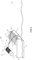
- the towed body 4 gradually rises to the surface. Due to the balancing of the towed body 4, the second end 43 arrives before the first end 42 at the surface of the water. When the second end 43 is above the surface of the water, the Archimedean thrust is no longer sufficient to keep the towed body 4 vertical, the second longitudinal end 43 of the towed body 4 tends to tilt under the the effect of its weight, that is to say to move away from the vertical orientation, to tend to adopt a substantially horizontal orientation (the longitudinal axis I is substantially horizontal) as shown in figure 2 .
- the two lines 6, 7 are long enough to be able to be supported and deflected by the deflector 60 as shown in figure 2 , while the towed body 4 is still submerged, when the towed device is towed, by the surface vessel.
- the two lines 6, 7 are long enough to be supported and deflected by the deflector 60 as shown in figure 2 , while the towed body 4 is still submerged, when the towed device is towed by the surface vessel when the speed is less than or equal to a maximum towing speed during recovery of the sonar device, in calm sea conditions.
- the maximum towing speed when recovering the body is less than 10 knots and, preferably, greater than or equal to 6 knots.
- the towed body 4 thus tilts progressively during the first winding stage, that is to say when the rotation of the first drum 13 around the axis x1 continues in the same direction so that the cable 2 exerts on the lines 6, 7, a traction towards the first drum in a plane substantially perpendicular to the axis x, until so that the second hanger 7 comes to bear on the deflector 60 to be deflected by the deflector 60 as shown in figure 2 .
- the two lines 6 and 7 When the two lines 6 and 7 are supported and deflected by the deflector 60, they are stretched between the deflector 60 and the towed object 4. As the two lines 6 and 7 have the same length and the deflector 60 has a substantially fixed section along the axis so-called handling orientation in which the longitudinal axis I is substantially parallel to the axis x of the deflector 60.
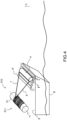
- the towed body 4 By continuing the rotation of the first drum 13 in the same direction, the towed body 4 completely emerged suspended from the lines 6 and 7 presents, in calm sea conditions, the handling attitude in which its longitudinal axis I is substantially parallel to the axis of the deflector as shown in Figure 3 .
- the orientation of the towed body 4 can vary but it is held more and more firmly in the handling orientation as the towed body 4 approaches the deflector 60, that is to say as the length of the portions of the lines 6 and 7 located between their support zones on the deflector 60 and the towed body 4 decreases.
- the freedom of movement of the towed body 4 is reduced, as visible in figures 3 And 4 , until it comes to rest on the deflector 60 and is recovered on board the surface building B as visible in figure 4 .
- the towed body is maintained substantially in the handling orientation by the two lines resting on the deflector until its immersion.
- the device for attaching by lines 6, 7 of the sonar device 301 according to the invention makes it possible to secure the launching and recovery of a towed body 4 from a surface building B, which limits the risk of shocks between the towed body 4 and the stern of the surface vessel B.
- This sonar device 301 is, due to the simplicity and relative security of the recovery and launching of the towed body 4 from a surface vessel, well suited in the case of use on board a USV.
- the recovery of the towed body 4 in the handling orientation makes it possible to provide an opening of reduced height at the rear of the surface building and to avoid the formation of trenches or recess in the deck of the surface building and to limit the size of the storage area of this towed body along the longitudinal axis of the surface building, that is to say along the axis perpendicular to the x axis.
- the handling orientation also favors its stable and space-saving storage on the drum of a winch with an axis substantially parallel to the x axis.
- the x axis is advantageously substantially perpendicular to the longitudinal axis of the surface building. This allows the towed body to be stored while being maintained in roll and pitch.
- the deflector 60 has substantially the shape of an angular portion, produced around the x axis, of a cylinder of x axis.
- the deflector 60 is formed by a roller mounted rotating relative to the supporting building around its axis of rotation x. This makes it possible to limit friction between the deflector 60 and the sonar device during launching and recovery operations.
- the roller R is fixed relative to the surface building B.
- the handling device comprises a set of adjacent cylindrical rollers R with longitudinal axes substantially parallel to each other and aligned along an axis which is substantially horizontal in calm sea conditions, and perpendicular to the x axis.
- the rollers R are configured and arranged so that the towed body 4, oriented so that the axis I is substantially parallel to the axis x, is able to rest on two rollers R which prevent the movement of the towed body 4 according to the axis along which the rollers R are aligned.
- the two adjacent rollers form a nest allowing the towed body 4 to be stored.
- the axis along which the rollers R are aligned can be inclined relative to the horizontal in calm sea conditions, as visible in Figure 4 , or horizontal by calm sea state as shown in figures 5 to 7 .
- the inclination is favorable to stable maintenance of the towed body in pitch under the effect of gravity and the traction of the lines.
- the inclination allows easy relaunch.
- the rollers R are dimensioned so that the towed body 4 resting on two adjacent rollers is only in direct physical contact with the two adjacent rollers R. This limits the risk of damage to the towed body 4.
- the axis x of the deflector 60 is substantially parallel to the first axis of rotation x1 of the first drum 13. These axes could alternatively not be parallel, for example in the case where a pulley deviates, in a horizontal plane, the axis of the tractor cable 2 between the deflector 60 and the first drum.
- the hangers 6 and 7 are fixed to the longitudinal ends of the elongated body.
- the fixing points 44 and 45 are located at the level, that is to say at zero distance, of the respective longitudinal ends 42 and 43 along the longitudinal axis I.
- At least one of the two fixing points 44, 45 is located at a distance, along the longitudinal axis I, from the longitudinal end near which it is located.
- the distance separating the first fixing point 44 from the first longitudinal end 42 along axis I is substantially the same as the distance separating the second fixing point 45 from the second longitudinal end 43 along axis I. This allows to promote the vertical orientation of the longitudinal transmitting antenna when towing. Alternatively, these two distances are different but this is less advantageous for the stability of the towed body when towing.
- the length of the lines 6 and 7 and the position of the deflector 60 are defined so that the lines 6 and 7 come to bear on the deflector, during the first winding stage, when the towed body 4 is completely submerged or at least partially submerged, in calm sea conditions, when the towing speed is less than or equal to the maximum towing speed during recovery.
- This characteristic makes it possible to stabilize the towed body, that is to say, to begin to limit its freedom of movement, before leaving the water.
- the length of the lines 6 and 7 and the position of the deflector 60 are defined so that the tractor cable 2 is supported on the deflector 60 and deflected by the deflector 60, during the first winding stage, when the towed body 4 is emerged and suspended from a portion of the tractor cable 2 extending between the hangers and an area of the tractor cable resting on the deflector 60.
- the towed body 4 is located at the end of the sonar device 301.
- the sonar device 301 does not have a flexible towed body of the type integrating a reception antenna and intended to be towed by the tractor cable 2 via the towed body 4.
- the sonar system differs from that of figures 1 to 4 , in that it comprises a sonar device 1 according to a second embodiment which differs from that of the figures 1 to 4 , in that it comprises a flexible elongated body 3 integrating a reception antenna 50 and intended to be towed by the tractor cable 2 via the towed body 4.
- the reception antenna 50 comprises a plurality of electroacoustic transducers 41 distributed along of the flexible elongated body 3.
- the flexible elongated body 3 possibly comprises, as visible in figures 6 to 7 , an intermediate cable 31 of neutral buoyancy connecting the reception antenna 50 of neutral buoyancy to the towed body 4 and/or a tail line 32 of neutral buoyancy connected to the towed body 4 by the reception antenna 50.
- the flexible elongated body 3 advantageously has substantially neutral buoyancy so as to extend horizontally when it is submerged and towed by the surface building B.
- the flexible elongated body 3 is connected to the tractor cable 2 via the towed body 4 which is itself connected to the flexible elongated body 3 so that the flexible elongated body 3 exerts traction on the towed body 4 at a third point of fixing 46 located near the first longitudinal end 42 of the towed body 4 and at a fourth fixing point 47 located near the second longitudinal end 43 of the towed body 4. This allows better control of the orientation of the towed body during of its recovery on board surface vessel B.
- the sonar device 1 comprises, for example, a third hanger 8 comprising a first end 8a attached to the towed body 4 at a third attachment point 46 (which located at the first longitudinal end 42, along the axis I, in the non-limiting realization of the Figure 5 ) of the towed body 4 and a second end 8b connected to a first end 3a of the flexible elongated body 3 and a fourth hanger 9 comprising a first end 9a attached to the towed body 4 at a fourth attachment point 47 (which is located at the level of the second longitudinal end 43, along axis I, in the non-limiting embodiment of the Figure 5 ) of the towed body 4 and a second end 9b connected to the first end 3a of the flexible elongated body 3.
- the third fixing point and the fourth fixing point are integral with each other.
- ends 8b and 9b are fixed relative to the end 3a of the flexible elongated element 3.
- the third fixing point 46 of the first end 8a of the third hanger 8 is located at the same distance from the first longitudinal end 42 of the towed body 4 as the first fixing point 44 of the second end 6b of the first hanger 6 and the fourth fixing point 47 of the first end 9a of the fourth hanger 9 is located at the same distance from the second longitudinal end 43 of the towed body 4 as the second fixing point 45 of the second end 7b of the second hanger 7.
- the lines 8 and 9 may have substantially the same length as the lines 6 and 7 or a different length.
- the lines 8 and 9 are arranged so as to form a V when they are tensioned.
- the V comprises a bottom secured to the first end 3a of the flexible elongated body 3.
- the behavior of the towed body 4 differs from that of the figures 1 to 4 in that during a first winding step during which the first drum 13 is rotated around the first axis x1 to wind the tractor cable 2 around the first drum 13, the traction exerted by the elongated element 3 flexible on the towed body 4 via the third hanger 8 and the fourth hanger 9 limits the inclination of the towed body 4 relative to the vertical plane containing the traction cable 2.
- the towed body 4 is rigid so as not to be deformed during its use, that is to say when towing the submerged sonar device, when recovering the sonar device and when putting it in the water .
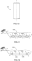
- the towed body 4 may be cylindrical or the body may be hydrodynamically profiled. It may generally have the shape of a drop of water in a plane substantially perpendicular to axis I like the towed body 400 represented in Figure 10 .
- the towed body 4 can be provided with a hydrodynamic coating having, in a non-limiting manner in figure 5 , a form of sail 5. This covering was not represented on the figures 6 to 7 .
- the sail 5 is, for example, installed between the lines 8 and 9 connecting the towed body 4 to the flexible elongated body 3. This sail makes it possible to limit the vibrations induced by vortex.
- Other types of hydrodynamic coverings such as for example sheaths fitted with hair or inflatable sails can be provided.
- the winch 311 only includes the first drum 13 which makes it possible to store the sonar device 301 of the figures 1 to 4 by continuing the rotation of the first drum in the same direction until the towed body 4 comes to bear on the first drum 13.
- this winch 311 is not optimal for storing a sonar device 1 such as on the figures 5 to 7 of the type comprising a flexible elongated body 3 at the tail. Indeed, it is not optimal to wind up the flexible elongated body 3.
- An aim of the invention is to propose a sonar system whose handling device makes it possible to ensure the storage of this type of sonar device and which is compact and not heavy.
- the handling device is configured to allow this device to be stored without requiring disconnection between the towed body and the flexible elongated body 3 and/or automatically.
- FIG. 8 An example of a submarine system comprising a handling device 10 according to another embodiment of the invention is shown schematically in perspective figure 8 and in side views Figure 9 in successive phases 1 to 4 during the implementation of a storage (or recovery) method of the underwater device 1 by means of the handling device 10 to store the underwater device on board the vessel surface.
- Figure 9 represents a phase located between phases 2 and 3 visible in Figure 3 .
- the handling device 10 comprises a winch 11 comprising a frame 12 visible only in figure 8 to clarify more.
- the frame 12 is intended to be fixed to a structure S of the building of surface B.
- the winch 11 comprises a first drum 13 able to rotate relative to the frame 12 around a first axis of rotation x1.
- This winch differs from that of figures 1 to 4 in that it comprises a second drum 14 surrounding the first drum 13 and being capable of rotating relative to the frame 12 around a second axis of rotation x2.
- the drums 13 and 14 are concentric in the non-limiting realization of the figures 8 And 9 so that the x2 axis is the x1 axis.
- the second drum 14, surrounding the first drum 13, has a larger diameter than the first drum 13.
- the winch 11 is able to be in a decoupling state in which the first drum 13 is able to be driven in rotation around the axis of rotation x1 relative to the frame 12 and is decoupled from the second drum 14 in rotation around the first axis of rotation x1 and around the second axis of rotation x2.
- the second drum 14 is capable, at least when the winch is in the decoupling state, of being in an open state, as shown in figures 8 And 9 (phases 1 and 2), in which the second drum 14 has a receiving opening 15.
- the receiving opening 15 can be crossed by the towed body 4 to penetrate inside the volume 140 delimited by the drums 13 and 14. This volume surrounds the first drum 13 and is surrounded by the second drum 14.
- the second drum 14 delimits a substantially cylindrical internal volume whose diameter corresponds to the diameter of the second drum.
- the winch 11 is capable of being in a coupling state in which the first drum 13 and the second drum 14 are coupled in rotation around the second axis of rotation x2.
- the drums 13 and 14 are integral in rotation around the second axis when the winch 11 is in the coupled state.
- the handling device 10 makes it possible to store, in a limited volume and on a single winch 11, a tractor cable 2 and an active sonar with a linear transmitting antenna 3, 6.
- the handling device according to the The invention makes it possible to store the tractor cable 2 around the first drum 13, the linear transmitting antenna in the volume delimited by the second drum and the linear receiving antenna around the second drum.
- This handling device is less expensive, less bulky and less heavy than a device which would use separate winches to recover the traction cable on the one hand and the flexible elongated body on the other hand.
- this configuration is particularly interesting for the storage of underwater devices according to the invention comprising an elongated towed body 4 intended to be stored without deforming, such as the sonar device according to the invention.
- the shape of a drum 14 makes it possible to provide a receiving opening 15 having the shape of a slot extending longitudinally along the axis x1 as shown in figures 8 And 9 , which an elongated towed body 4 can cross with its longitudinal axis substantially parallel to the axis x1, during the first winding stage, without undergoing deformation.
- the device thus makes it possible to produce towed bodies with linear transmitting antennas that are relatively heavy and long and non-deformable.
- the receiving opening 15 extends substantially over the entire length of the second drum 14 along the first axis of rotation x1.
- the reception opening 15 extends over part of the length of the second drum 14 along the first axis of rotation x1.
- the second drum 14 is able to be positioned, and preferably immobilized, in an angular receiving position, around the second axis x2, in which the receiving opening 15 is able to be crossed by the tractor cable 2 and/or or the towed body 4, preferably, but not necessarily, during the first winding stage, as visible in figures 8 And 9 .
- the storage of the underwater device does not require manual or automatic operation to disconnect the towed body and the tractor cable.
- the receiving opening must then be dimensioned so that the towed body can pass through it during the first winding stage depending on the orientation in which it is presented in relation to the opening. It must in particular have a greater length, along the axis x1, than the length of the towed body 4 along the longitudinal axis I.
- the towed body 4 comes to bear on the first drum 13, under the effect of driving the first drum in rotation around the axis x1.
- the method of handling an underwater device is thus easily automatable, which makes it possible to avoid the intervention of a human operator and the associated risks and allows the storage of the underwater device on board a USV.
- the step of inserting the towed body 4 into the volume 140 by passing through the receiving opening 15 can be carried out subsequently to the first winding step, for example, by a human operator or a tool .
- the same plane perpendicular to the axis x1 is located equidistant from the two longitudinal ends of the first drum 13 and equidistant from the two longitudinal ends of the second drum 14.
- first drum 13 and the second drum 14 have the same length along the axis x1.
- the second drum 14 surrounds the first drum over the entire length of the first drum 13 along the axis x1.
- the drums 13 and 14 are offset relative to each other along the axis x1.
- the second drum 14 is longer than the first drum 13 along the axis x1 which makes it possible to wind up a greater length of flexible elongated body 3, or conversely, the second drum 14 is shorter than the first drum 13 along axis x1, which allows a greater length of tractor cable 2 to be wound.
- the towed body 4 is capable of entering the volume 140 through the receiving opening 15 to be stored in the volume 140 without leaving radially (relative to the axis x2) of the volume 140.
- the towed body 4 is inside the cylinder, the diameter of which is the diameter of the second drum, formed around x2 along the entire length of the second drum along the axis x1. The winding of the flexible elongated body 3 around the second drum 14 after storage of the towed body 4 in the volume 140 is then not hindered by the towed body 4.
- the towed body 4 is capable of penetrating into the volume 140 through the receiving opening 15 to be stored in the volume 140 without leaving radially (relative to the axis x2) of the volume 140 once the cable tractor is wound around the first drum 13.
- the towed body 4 is able to be entirely stored in the volume 140.
- the towed body 4 could protrude from the volume 140 along the axis x2, for example, when the first drum 13 is longer than the second drum 14 .
- the invention also relates to a method of recovering and launching the underwater device, capable of being implemented by the handling device according to the invention.
- the handling device can be configured to implement these methods when a recovery or release condition is verified, for example, when a control device of the handling device receives a storage or respectively order. deployment.
- the second drum 14 is able to be positioned, and preferably immobilized, in an angular position called reception, around the axis x2, in which the reception opening 15 is capable of being crossed by the tractor cable 2 and the towed body 4, during the first winding stage.
- the receiving opening 15 must then be sized so that the towed body can pass through it during the first winding stage depending on the orientation in which it is presented in relation to the opening.
- the towed body 4 comes to bear on the first drum 13, under the effect of driving the first drum 13 in rotation around the axis x1.
- the second drum 14 is rotated around the axis x2 in the same direction as the direction of rotation of the first drum 13 during the first winding stage.
- the process for recovering the underwater device initially deployed is thus easily automatable, which makes it possible to avoid the intervention of a human operator and the associated risks and allows the storage of the underwater device on board a USV.
- the towed body 4 does not enter the volume 140 through the receiving opening 15 under the effect of the rotation of the first drum 13 around the axis x1.
- the step of inserting the towed body 4 into the volume 140 by passing through the receiving opening 15 can be carried out subsequently to the first winding step, for example, by a human operator or a tool.
- the method also comprises, once the body is inserted into volume 140, a step of coupling, the first drum 13 and the second drum 14 in rotation around the second axis of rotation x2 relative to the frame 12 to put the winch 11 in the coupling state.
- This step is implemented by the coupling/decoupling means.
- drums 13 and 14 concentric.
- This embodiment makes it possible to provide a simple and lightweight handling device.
- the two drums can, for example, be rotated relative to the frame, when the winch is in the decoupling state and in the coupling state, by the same shaft itself rotated by a single motor.
- the coupling/decoupling means can be made very simply by mounting the first drum secured to the shaft, by mounting the second drum in pivot connection on the first shaft and by providing a coupler making it possible to make the second drum alternately secured to the shaft and free to rotate around the axis of rotation x1 by relation to the tree.
- the coupling/decoupling means are, for example, conventional means for those skilled in the art which are, for example, made in the form of a clutch or based on a brake coupled to a jaw secured to one of the parts or on a motor coupled to a toothed ring or even a connecting pin.
- the handling device with concentric drums is particularly suited to the storage of an underwater device 1 having a towed body 4, for example a linear transmitting antenna, produced in the form of a cylindrical object with a circular section or not, for example with a section substantially in the shape of a drop of water.
- the cylindrical towed body 4 can come to bear on a winding of the tractor cable 2, previously produced around the first drum 13, on each turn of a layer of this winding, which is favorable to good stability of the towed body 4 on the first drum 13.
- the x1 axis is distant from the x2 axis.
- This embodiment makes it possible to store, in the volume delimited by the second drum 214, an object of large dimensions in the plane perpendicular to the axis x1 without having to increase the diameter of the second drum 214 significantly and/or to store a body of complex shape.
- the axes are, for example, spaced apart along a horizontal axis, by calm sea state, and perpendicular to the x1 axis.
- the first drum 13 is, for example, rotatably mounted around a shaft of axis x1 fixed to the second drum 214, for example to a shell 212 of the second drum 214.
- the shell 212 will be described later.
- the coupling/decoupling means may comprise first coupling/decoupling means allowing alternately to secure and disconnect the first drum 13 from the shaft on which it is mounted and means for immobilizing the second drum, around the axis x2 relative to the frame 12 allowing alternately to join and separate the second drum from the frame in rotation around the axis x2.
- the decoupling state is obtained by decoupling the first drum 13 with the shaft around the axis x1 and by immobilizing the second drum 214 around the axis x2 relative to the frame 12.
- the coupling state is obtained by coupling the first drum 13 to the shaft.
- a first motor is provided to enable the first drum 13 to rotate around the axis x1 relative to the frame.
- a second motor is provided to enable the second drum 214 to rotate around the axis x2 relative to the frame.
- the second drum 14 presents, as visible in Figure 9 , a shell 114 having the shape of a generally cylindrical shell in which the receiving opening 15 is provided.
- the drum 14 of figures 8 And 9 is capable of being only in the open state.
- the second drum 14 is configured so that winding of an elongated flexible element 3 around the second drum 14 is possible when the second drum 14 is in the open state.
- the receiving opening 115 extends over an angle less than or equal to 20° and, preferably, less than or equal to 15° to allow correct winding of the flexible elongated body 3 around the second drum 14.
- the winch 11 of the figures 8 And 9 could be capable of being alternately in the open state and in a closed state in which the receiving opening is at least partially closed as shown in figures 5 to 7 . Winding of the flexible elongated element is then possible only in the closed state or in the closed state and in the open state.
- the handling device 210 differs from the handling device of figures 8 And 9 , in particular by the winch 211 which comprises a second drum 214 which is distinguished from the second drum 14 of the figures 8 And 9 , in that it is capable of being alternately in an open state, as represented in figure 5 And 6 , in which it has a receiving opening 215 through which the towed body 4 can pass to penetrate inside the volume 240 delimited by the second drum 214 and the first drum 13 and surrounding the first drum 13, and in a closed state, as shown in Figure 7 , in which the receiving opening 215 is at least partially closed.
- the winch 211 which comprises a second drum 214 which is distinguished from the second drum 14 of the figures 8 And 9 , in that it is capable of being alternately in an open state, as represented in figure 5 And 6 , in which it has a receiving opening 215 through which the towed body 4 can pass to penetrate inside the volume 240 delimited by the second drum 214 and the first drum 13 and surrounding the first drum 13, and in a closed state, as
- This type of configuration makes it possible to provide a large reception opening in the drum and thus to receive, inside the volume delimited by the second drum 214, large towed bodies, for example in a plane perpendicular to the axis x2. Furthermore, a large opening leaves more room for possible manipulation of the towed body, by a machine or an operator.
- the second drum 214 comprises a movable cover 213 relative to a first part 212 of the second drum 214 and capable of being in a first position ( figures 5 And 6 ) in which the cover 213 opens the second drum 214 so that it includes the receiving opening 215 and in a second position ( figure 7 ) in which the cover 213 substantially closes the receiving opening 15 so that the second drum 214 has substantially a cylindrical shape.
- a residual slot advantageously allows a connection zone between the towed body and the flexible elongated body 3 or the flexible elongated body 3 to pass.
- the second drum 214 comprises a shell 212 having substantially the shape of an angular portion of a cylinder formed around the axis x2.
- the shell 212 extends angularly around the axis x2, from a first axial edge 216 substantially parallel to the axis x2 to a second axial edge 217 substantially parallel to the axis x2.
- the cover 213 has a shape substantially complementary to the shell 212 and is mounted pivoting relative to the shell 212 around an axis of rotation of the cover x3 parallel to the axis x2 near the edge 216 so that the cover 213 is able to move from the first position shown in Figure 5 to the second position shown in Figure 7 by a rotation relative to the first part around the axis x3.
- the storage (or recovery) method comprises an opening step, implemented by opening means or by an operator, to move the second drum from the closed state to the open state.
- This opening step can be implemented before the first winding step or during or after the first winding step but before insertion of the towed body.
- the method comprises, after the step of inserting the towed body and before the second winding step, a step of closing the second drum 214 to allow the winding of the elongated element 3 around the second drum.
- the step of inserting the towed body 4 into the volume 140 by passing through the receiving opening 15 is carried out subsequently to the first winding step, for example, by a human operator or a tool.
- the step is carried out, as in figures 8 And 9 , during the first winding stage under the effect of the rotation of the first drum around the axis x1.
- the handling device advantageously comprises fixing means SF, SP, as shown in Figure 7 , from the towed body 4 to the second drum 214 and, more particularly, to the hull 212, configured to make the towed body integral with the second drum 14 in rotation around the axis x2.
- fixing means include, for example, a support SP intended to support the towed body 4 and fixed with respect to the hull 212 or with respect to the hood and means for fixing SF of the towed body 4 to the support SP. This type of means can also be provided when the drums are coaxial.
- the second drum 214 capable of being in the open and closed state is, for example, configured, as on the figures 5 And 6 , so that winding a flexible elongated body, for example body 3, around the second drum 214 is impossible in the open state and possible in the closed state.
- the second drum is configured such that winding of a cable around the second drum is possible in the open state and in the closed state.
- the cover is, for example, of the rotating shutter type, having, for example, the shape of a cylinder portion with a diameter very slightly less than the diameter of the second drum and capable of pivoting around the axis x2 to close or open the second drum.
- the winch can include two flanges F1, F2 delimiting the drums along the axis x1.
- at least one flange has an opening O allowing an operator to access the volume 140 so as to allow maintenance of the towed body 4 stored in the volume 140.
- This type of means can also be provided when the drums are coaxial.
- the handling device comprises a deflector 60 arranged upstream of the first drum 13, seen from the towed body 4, the first line 6 and the second line 7 initially submerged, during the first winding step.
- the lines are able to come to bear on the deflector 60 before winding around the first drum 13 during the first winding step.
- the deflector 60 is arranged near the stern PO of the surface vessel B so that the towed body 4 has the handling orientation (x substantially parallel to I) before its arrival on board the surface vessel B.
- the deflector 60 is, for example, the first element of the handling device and/or the surface vessel, encountered by the lines during a recovery/storage process of the sonar device initially deployed and towed by the surface vessel. This makes it possible to limit the risk of collisions between the towed body 4 and the stern of the ship. This also makes it possible to avoid the design of large openings at the rear of the supporting building to allow a linear transmitting antenna to be recovered and to avoid creating a trench (“recess” in Anglo-Saxon terminology) in the bridge. main surface building in order to be able to store a linear transmitting antenna that is too high to be accommodated between the main deck and the upper deck.
- the deflector 160 of the handling device figures 8 And 9 differs from that of figures 1 to 7 in that it is closer to the first drum 13 and, more particularly, to the opening 15 so that the towed body passes through the opening 15 substantially in the handling orientation (I substantially parallel to the axis of the deflector 160 along which the deflector 160 extends longitudinally). This makes it possible to limit the risks of collisions between the towed body 4 and the second drum 14 when it passes through the receiving opening 15 and thus to limit the risks of jamming when it arrives on the drum.
- the deflector 160 is arranged upstream of the drum 13 and mounted on the second drum 14 so as to delimit the receiving opening 15.
- a deflector 160 can be arranged so that the towed body 4 passes through the opening 15 substantially in the handling orientation and/or comes to bear on the drum 13 substantially in the handling orientation.
- This type of deflector 160 is arranged between the stern of the surface vessel and the first drum 13 for example, between a deflector 60 and the first drum 13.
- This deflector 160 forms, for example, part of the winch by being, for example, arranged upstream of the first drum 13, for example upstream of the receiving opening 15 (during the first winding step), or at the level of the receiving opening 15.
- the first drum 13 also constitutes a deflector making it possible to bring the towed body 4 substantially in the handling orientation on the first drum 13.
- the handling device comprises a single deflector formed by the first drum 13.
- the invention relates to a method for recovering the sonar device from a surface vessel comprising a first winding step during which the first drum 13 is rotated around the first axis x1 so that the tractor cable 2 comes to wind around the first drum 13, and so that the first hanger 6 and the second hanger 7 come to bear on the deflector 60 to be deflected by the deflector so that the longitudinal axis of the towed body 4 is oriented substantially parallel to the axis of the deflector x, when the towed body 4 is completely emerged and suspended from the first line 6 and the second line 7.
- the invention relates to a sonar system configured to put implement this step during a recovery process which is for example implemented when a recovery condition is respected.
- the sonar system then comprises control means for controlling the handling device so as to implement the method.
- the invention relates to a method of launching the sonar device from a surface vessel comprising a first unwinding step during which the first drum 13 is rotated around the first axis x1 so that the tractor cable 2 comes to unwind from the first drum 13, and so that the first hanger 6 and the second hanger 7 come to bear on the deflector 60 to be deflected by the deflector so that the longitudinal axis of the towed body 4 is oriented substantially parallel to the axis of the deflector x, when the towed body 4 is completely emerged and suspended from the first hanger 6 and the second hanger 7.
- the invention relates to a sonar system configured to implement this step during a launching process which is for example implemented when a recovery condition is respected.
- the sonar system then includes a control device for controlling the handling device so as to implement the method.
- the winch comprises a single second drum 14.
- the winch comprises a set of several second drums as defined previously. These second drums have different diameters so as to surround each other.
- Each second drum 14 has an opening giving access to the volume located between this second drum and the drum of directly lower diameter. This makes it possible, for example, to recover different towed bodies in the volume delimited between each second drum and the drum of directly lower diameter or to be able to wind up portions of flexible elongated elements of different flexibility on drums of different diameters.
- All the drums can be rotationally coupled and each drum can be rotationally decoupled from the other drums.
- the underwater device comprises a single towed body.
- the underwater device comprises a set of several towed bodies.
- the handling device can then include one or more second drums.
- Each towed body is advantageously elongated along a longitudinal axis and has the same length but this is not obligatory.
- the underwater device comprises, for example, a set of several towed bodies 4.
- the towed bodies 4 are connected to each other, to the tractor cable 2 and to the flexible elongated element 3 so as to be distributed along a curved towing line defined by the towing cable and the flexible elongated element when the underwater device is towed by the surface vessel, the set of towed bodies being distributed along the towing line.
- the underwater device 1000 comprises several towed bodies 4 distributed along the towing line defined by the cable 2 and the flexible elongated body 3 and drawn in dotted lines between the two.
- the towed bodies 4 are connected to each other by intermediate lines 1001a, 1001b.
- the system is, for example, configured so as to store or allow several towed bodies to rest on the first drum 13 or, more generally, between the first drum 13 and the second drum 14 or so as to store or allow to store different towed bodies in successive volumes defined between successive adjacent drums or resting on successive drums.
- the towed bodies 4 are connected two by two by intermediate lines 1001a, 1001b via hangers.
- Each intermediate body is fixed to a first and a second hanger 6, 7 connecting it to the tractor cable and to a third and a fourth hanger 8, 9 connecting it to the flexible elongated body.
- the towed bodies 4 are connected two by two by sets of intermediate lines 1003, 1004 and 1005, 1006.
- One of the towed bodies is fixed to a first and a second hanger 6, 7 connecting it to the cable.
- This towed body is connected to the adjacent towed body by several intermediate lines 1003,1004, substantially parallel in towing.
- This towed body is itself connected to the last adjacent towed body by intermediate lines 1005,1006.
- the last towed body is fixed to a third and a fourth hanger 8, 9 connecting it to the flexible elongated body.
- Each intermediate line is a flexible elongated element which can be produced in the form of a cable, for example an electrotractor cable.
- Each intermediate line may include at least one electroacoustic transducer. It can integrate an acoustic antenna, for example, an acoustic reception antenna.
- the control device for controlling the handling device may comprise one or more dedicated electronic circuits or a circuit for general use.
- Each electronic circuit may include a reprogrammable calculation machine (a processor or a micro controller for example) and/or a calculator executing a program comprising a sequence of instructions and/or a dedicated calculation machine (for example a set of logic gates such as an FPGA, a DSP or an ASIC, or any other hardware module).
Landscapes
- Life Sciences & Earth Sciences (AREA)
- Physics & Mathematics (AREA)
- Engineering & Computer Science (AREA)
- General Life Sciences & Earth Sciences (AREA)
- Acoustics & Sound (AREA)
- Environmental & Geological Engineering (AREA)
- Geology (AREA)
- Remote Sensing (AREA)
- General Physics & Mathematics (AREA)
- Geophysics (AREA)
- Chemical & Material Sciences (AREA)
- Combustion & Propulsion (AREA)
- Mechanical Engineering (AREA)
- Ocean & Marine Engineering (AREA)
- Oceanography (AREA)
- Measurement Of Velocity Or Position Using Acoustic Or Ultrasonic Waves (AREA)
Applications Claiming Priority (2)
| Application Number | Priority Date | Filing Date | Title |
|---|---|---|---|
| FR1905728A FR3096652B1 (fr) | 2019-05-29 | 2019-05-29 | Dispositif sonar, systeme sonar |
| PCT/EP2020/061830 WO2020239345A1 (fr) | 2019-05-29 | 2020-04-29 | Dispositif sonar, systeme sonar |
Publications (3)
| Publication Number | Publication Date |
|---|---|
| EP3976460A1 EP3976460A1 (fr) | 2022-04-06 |
| EP3976460C0 EP3976460C0 (fr) | 2024-03-27 |
| EP3976460B1 true EP3976460B1 (fr) | 2024-03-27 |
Family
ID=68138363
Family Applications (1)
| Application Number | Title | Priority Date | Filing Date |
|---|---|---|---|
| EP20720835.6A Active EP3976460B1 (fr) | 2019-05-29 | 2020-04-29 | Dispositif sonar, systeme sonar |
Country Status (9)
| Country | Link |
|---|---|
| US (1) | US12195140B2 (pl) |
| EP (1) | EP3976460B1 (pl) |
| AU (1) | AU2020282543B2 (pl) |
| CA (1) | CA3142177A1 (pl) |
| ES (1) | ES2985907T3 (pl) |
| FR (1) | FR3096652B1 (pl) |
| PL (1) | PL3976460T3 (pl) |
| SG (1) | SG11202113183QA (pl) |
| WO (1) | WO2020239345A1 (pl) |
Families Citing this family (1)
| Publication number | Priority date | Publication date | Assignee | Title |
|---|---|---|---|---|
| CN116946331B (zh) * | 2023-06-09 | 2024-07-16 | 南方电网调峰调频发电有限公司储能科研院 | 深水隧洞用大型声呐伸缩机构 |
Family Cites Families (8)
| Publication number | Priority date | Publication date | Assignee | Title |
|---|---|---|---|---|
| US3966171A (en) | 1972-02-29 | 1976-06-29 | Fathom Oceanology Limited | Apparatus for launching towing and recovering a submersible body from a vessel |
| FR2925231B1 (fr) | 2007-12-18 | 2009-11-27 | Thales Sa | Antenne sonar d'emission a axe vertical enroulable sur un treuil |
| FR2964201B1 (fr) | 2010-08-30 | 2013-08-16 | Cggveritas Services Sa | Dispositif d'emission d'ondes sismiques pour l'acquisition sismique marine et procede pour sa mise en oeuvre |
| US8967067B2 (en) * | 2010-12-07 | 2015-03-03 | Thales | System for launching and recovering underwater vehicles, notably towed underwater vehicles |
| US9001623B1 (en) | 2011-12-06 | 2015-04-07 | Raytheon Company | Sonar systems and sonar methods that use a tow body having a towed acoustic projector for which an orientation can be changed while being towed |
| CA2903227A1 (en) | 2015-09-04 | 2017-03-04 | Janis NAMS | Tow body arrangement for a towable device in a sonar system |
| DE102015116750A1 (de) | 2015-10-02 | 2017-04-06 | Atlas Elektronik Gmbh | Schallwandleranordnung, Schleppsonar, Winde, Schleppschiff und Verfahren zum Ausbringen und/oder Einholen einer Schallwandleranordnung |
| GB2564523B (en) * | 2017-05-04 | 2020-09-02 | Pgs Geophysical As | Marine survey apparatus, system, and method with a rigid structure |
-
2019
- 2019-05-29 FR FR1905728A patent/FR3096652B1/fr active Active
-
2020
- 2020-04-29 EP EP20720835.6A patent/EP3976460B1/fr active Active
- 2020-04-29 US US17/614,994 patent/US12195140B2/en active Active
- 2020-04-29 AU AU2020282543A patent/AU2020282543B2/en active Active
- 2020-04-29 CA CA3142177A patent/CA3142177A1/en active Pending
- 2020-04-29 ES ES20720835T patent/ES2985907T3/es active Active
- 2020-04-29 WO PCT/EP2020/061830 patent/WO2020239345A1/fr not_active Ceased
- 2020-04-29 SG SG11202113183QA patent/SG11202113183QA/en unknown
- 2020-04-29 PL PL20720835.6T patent/PL3976460T3/pl unknown
Also Published As
| Publication number | Publication date |
|---|---|
| PL3976460T3 (pl) | 2024-05-13 |
| WO2020239345A1 (fr) | 2020-12-03 |
| AU2020282543A1 (en) | 2022-01-06 |
| EP3976460C0 (fr) | 2024-03-27 |
| SG11202113183QA (en) | 2021-12-30 |
| ES2985907T3 (es) | 2024-11-07 |
| AU2020282543B2 (en) | 2025-08-14 |
| US12195140B2 (en) | 2025-01-14 |
| FR3096652B1 (fr) | 2021-05-07 |
| FR3096652A1 (fr) | 2020-12-04 |
| US20220234692A1 (en) | 2022-07-28 |
| CA3142177A1 (en) | 2020-12-03 |
| EP3976460A1 (fr) | 2022-04-06 |
Similar Documents
| Publication | Publication Date | Title |
|---|---|---|
| EP2043913B1 (fr) | Appareil de recuperation d'un engin sous-marin ou marin | |
| EP2043911B1 (fr) | Installation et procede de recuperation d'un engin sous-marin ou marin | |
| EP2885202B1 (fr) | Dispositif de mise a l'eau et de recuperation d'un sonar remorque | |
| EP2855252B1 (fr) | Systeme de mise a l'eau et de recuperation d'engins sous-marins, notamment d'engins sous-marins tractes | |
| EP3976461B1 (fr) | Dispositif sous-marin et systeme sous-marin | |
| FR2925231A1 (fr) | Antenne sonar d'emission a axe vertical enroulable sur un treuil | |
| EP3906188B1 (fr) | Dispositif d'accueil pour un vehicule sous-marin | |
| EP3902742A1 (fr) | Dispositif d'accueil pour un vehicule sous-marin | |
| EP2776309B1 (fr) | Dispositif de remorquage a chaumard articule | |
| WO2008043823A1 (fr) | Dispositif pour l'arrimage et le desarrimage automatique d'un emetteur sonar remorque a une ligne de remorquage d'un sonar actif. | |
| EP3209546B1 (fr) | Système de mise a l'eau et de récuperation d'engin marin et sous-marin assisté par des protections inclinables | |
| EP3976460B1 (fr) | Dispositif sonar, systeme sonar | |
| EP0504049A1 (fr) | Procédé et dispositif de déploiement d'un câble de filotransmission d'un engin sous-marin à partir d'une plate-forme de lancement | |
| WO2019121743A1 (fr) | Poisson à portance hydrodynamique variable de façon réversible et ligne de remorquage comprenant le poisson | |
| WO2021130333A1 (fr) | Dispositif de recuperation d'un navire a la mer | |
| EP4041625B1 (fr) | Dispositif sous-marin remorque et systeme de manutention du dispositif sous-marin | |
| EP3871000B1 (fr) | Système sonar | |
| EP4526201B1 (fr) | Dispositif sous-marin remorqué |
Legal Events
| Date | Code | Title | Description |
|---|---|---|---|
| STAA | Information on the status of an ep patent application or granted ep patent |
Free format text: STATUS: UNKNOWN |
|
| STAA | Information on the status of an ep patent application or granted ep patent |
Free format text: STATUS: THE INTERNATIONAL PUBLICATION HAS BEEN MADE |
|
| PUAI | Public reference made under article 153(3) epc to a published international application that has entered the european phase |
Free format text: ORIGINAL CODE: 0009012 |
|
| STAA | Information on the status of an ep patent application or granted ep patent |
Free format text: STATUS: REQUEST FOR EXAMINATION WAS MADE |
|
| 17P | Request for examination filed |
Effective date: 20211115 |
|
| AK | Designated contracting states |
Kind code of ref document: A1 Designated state(s): AL AT BE BG CH CY CZ DE DK EE ES FI FR GB GR HR HU IE IS IT LI LT LU LV MC MK MT NL NO PL PT RO RS SE SI SK SM TR |
|
| DAV | Request for validation of the european patent (deleted) | ||
| DAX | Request for extension of the european patent (deleted) | ||
| GRAP | Despatch of communication of intention to grant a patent |
Free format text: ORIGINAL CODE: EPIDOSNIGR1 |
|
| STAA | Information on the status of an ep patent application or granted ep patent |
Free format text: STATUS: GRANT OF PATENT IS INTENDED |
|
| INTG | Intention to grant announced |
Effective date: 20231207 |
|
| GRAS | Grant fee paid |
Free format text: ORIGINAL CODE: EPIDOSNIGR3 |
|
| GRAA | (expected) grant |
Free format text: ORIGINAL CODE: 0009210 |
|
| STAA | Information on the status of an ep patent application or granted ep patent |
Free format text: STATUS: THE PATENT HAS BEEN GRANTED |
|
| AK | Designated contracting states |
Kind code of ref document: B1 Designated state(s): AL AT BE BG CH CY CZ DE DK EE ES FI FR GB GR HR HU IE IS IT LI LT LU LV MC MK MT NL NO PL PT RO RS SE SI SK SM TR |
|
| RAP3 | Party data changed (applicant data changed or rights of an application transferred) |
Owner name: THALES |
|
| REG | Reference to a national code |
Ref country code: GB Ref legal event code: FG4D Free format text: NOT ENGLISH |
|
| REG | Reference to a national code |
Ref country code: CH Ref legal event code: EP |
|
| REG | Reference to a national code |
Ref country code: DE Ref legal event code: R096 Ref document number: 602020027915 Country of ref document: DE |
|
| REG | Reference to a national code |
Ref country code: IE Ref legal event code: FG4D Free format text: LANGUAGE OF EP DOCUMENT: FRENCH |
|
| U01 | Request for unitary effect filed |
Effective date: 20240411 |
|
| U07 | Unitary effect registered |
Designated state(s): AT BE BG DE DK EE FI FR IT LT LU LV MT NL PT SE SI Effective date: 20240422 |
|
| U20 | Renewal fee for the european patent with unitary effect paid |
Year of fee payment: 5 Effective date: 20240424 |
|
| PG25 | Lapsed in a contracting state [announced via postgrant information from national office to epo] |
Ref country code: GR Free format text: LAPSE BECAUSE OF FAILURE TO SUBMIT A TRANSLATION OF THE DESCRIPTION OR TO PAY THE FEE WITHIN THE PRESCRIBED TIME-LIMIT Effective date: 20240628 |
|
| PG25 | Lapsed in a contracting state [announced via postgrant information from national office to epo] |
Ref country code: RS Free format text: LAPSE BECAUSE OF FAILURE TO SUBMIT A TRANSLATION OF THE DESCRIPTION OR TO PAY THE FEE WITHIN THE PRESCRIBED TIME-LIMIT Effective date: 20240627 Ref country code: HR Free format text: LAPSE BECAUSE OF FAILURE TO SUBMIT A TRANSLATION OF THE DESCRIPTION OR TO PAY THE FEE WITHIN THE PRESCRIBED TIME-LIMIT Effective date: 20240327 |
|
| PG25 | Lapsed in a contracting state [announced via postgrant information from national office to epo] |
Ref country code: RS Free format text: LAPSE BECAUSE OF FAILURE TO SUBMIT A TRANSLATION OF THE DESCRIPTION OR TO PAY THE FEE WITHIN THE PRESCRIBED TIME-LIMIT Effective date: 20240627 Ref country code: HR Free format text: LAPSE BECAUSE OF FAILURE TO SUBMIT A TRANSLATION OF THE DESCRIPTION OR TO PAY THE FEE WITHIN THE PRESCRIBED TIME-LIMIT Effective date: 20240327 Ref country code: GR Free format text: LAPSE BECAUSE OF FAILURE TO SUBMIT A TRANSLATION OF THE DESCRIPTION OR TO PAY THE FEE WITHIN THE PRESCRIBED TIME-LIMIT Effective date: 20240628 |
|
| PG25 | Lapsed in a contracting state [announced via postgrant information from national office to epo] |
Ref country code: IS Free format text: LAPSE BECAUSE OF FAILURE TO SUBMIT A TRANSLATION OF THE DESCRIPTION OR TO PAY THE FEE WITHIN THE PRESCRIBED TIME-LIMIT Effective date: 20240727 |
|
| PG25 | Lapsed in a contracting state [announced via postgrant information from national office to epo] |
Ref country code: SM Free format text: LAPSE BECAUSE OF FAILURE TO SUBMIT A TRANSLATION OF THE DESCRIPTION OR TO PAY THE FEE WITHIN THE PRESCRIBED TIME-LIMIT Effective date: 20240327 |
|
| PG25 | Lapsed in a contracting state [announced via postgrant information from national office to epo] |
Ref country code: CZ Free format text: LAPSE BECAUSE OF FAILURE TO SUBMIT A TRANSLATION OF THE DESCRIPTION OR TO PAY THE FEE WITHIN THE PRESCRIBED TIME-LIMIT Effective date: 20240327 |
|
| PG25 | Lapsed in a contracting state [announced via postgrant information from national office to epo] |
Ref country code: SK Free format text: LAPSE BECAUSE OF FAILURE TO SUBMIT A TRANSLATION OF THE DESCRIPTION OR TO PAY THE FEE WITHIN THE PRESCRIBED TIME-LIMIT Effective date: 20240327 |
|
| PG25 | Lapsed in a contracting state [announced via postgrant information from national office to epo] |
Ref country code: SM Free format text: LAPSE BECAUSE OF FAILURE TO SUBMIT A TRANSLATION OF THE DESCRIPTION OR TO PAY THE FEE WITHIN THE PRESCRIBED TIME-LIMIT Effective date: 20240327 Ref country code: SK Free format text: LAPSE BECAUSE OF FAILURE TO SUBMIT A TRANSLATION OF THE DESCRIPTION OR TO PAY THE FEE WITHIN THE PRESCRIBED TIME-LIMIT Effective date: 20240327 Ref country code: RO Free format text: LAPSE BECAUSE OF FAILURE TO SUBMIT A TRANSLATION OF THE DESCRIPTION OR TO PAY THE FEE WITHIN THE PRESCRIBED TIME-LIMIT Effective date: 20240327 Ref country code: IS Free format text: LAPSE BECAUSE OF FAILURE TO SUBMIT A TRANSLATION OF THE DESCRIPTION OR TO PAY THE FEE WITHIN THE PRESCRIBED TIME-LIMIT Effective date: 20240727 Ref country code: CZ Free format text: LAPSE BECAUSE OF FAILURE TO SUBMIT A TRANSLATION OF THE DESCRIPTION OR TO PAY THE FEE WITHIN THE PRESCRIBED TIME-LIMIT Effective date: 20240327 |
|
| REG | Reference to a national code |
Ref country code: ES Ref legal event code: FG2A Ref document number: 2985907 Country of ref document: ES Kind code of ref document: T3 Effective date: 20241107 |
|
| REG | Reference to a national code |
Ref country code: CH Ref legal event code: PL |
|
| REG | Reference to a national code |
Ref country code: DE Ref legal event code: R097 Ref document number: 602020027915 Country of ref document: DE |
|
| PG25 | Lapsed in a contracting state [announced via postgrant information from national office to epo] |
Ref country code: MC Free format text: LAPSE BECAUSE OF FAILURE TO SUBMIT A TRANSLATION OF THE DESCRIPTION OR TO PAY THE FEE WITHIN THE PRESCRIBED TIME-LIMIT Effective date: 20240327 |
|
| PG25 | Lapsed in a contracting state [announced via postgrant information from national office to epo] |
Ref country code: MC Free format text: LAPSE BECAUSE OF FAILURE TO SUBMIT A TRANSLATION OF THE DESCRIPTION OR TO PAY THE FEE WITHIN THE PRESCRIBED TIME-LIMIT Effective date: 20240327 Ref country code: CH Free format text: LAPSE BECAUSE OF NON-PAYMENT OF DUE FEES Effective date: 20240430 |
|
| PLBE | No opposition filed within time limit |
Free format text: ORIGINAL CODE: 0009261 |
|
| STAA | Information on the status of an ep patent application or granted ep patent |
Free format text: STATUS: NO OPPOSITION FILED WITHIN TIME LIMIT |
|
| 26N | No opposition filed |
Effective date: 20250103 |
|
| PG25 | Lapsed in a contracting state [announced via postgrant information from national office to epo] |
Ref country code: IE Free format text: LAPSE BECAUSE OF NON-PAYMENT OF DUE FEES Effective date: 20240429 |
|
| U20 | Renewal fee for the european patent with unitary effect paid |
Year of fee payment: 6 Effective date: 20250320 |
|
| PGFP | Annual fee paid to national office [announced via postgrant information from national office to epo] |
Ref country code: PL Payment date: 20250318 Year of fee payment: 6 |
|
| PGFP | Annual fee paid to national office [announced via postgrant information from national office to epo] |
Ref country code: GB Payment date: 20250313 Year of fee payment: 6 |
|
| PGFP | Annual fee paid to national office [announced via postgrant information from national office to epo] |
Ref country code: ES Payment date: 20250509 Year of fee payment: 6 |
|
| PGFP | Annual fee paid to national office [announced via postgrant information from national office to epo] |
Ref country code: NO Payment date: 20250409 Year of fee payment: 6 |
|
| PG25 | Lapsed in a contracting state [announced via postgrant information from national office to epo] |
Ref country code: CY Free format text: LAPSE BECAUSE OF FAILURE TO SUBMIT A TRANSLATION OF THE DESCRIPTION OR TO PAY THE FEE WITHIN THE PRESCRIBED TIME-LIMIT; INVALID AB INITIO Effective date: 20200429 |
|
| PG25 | Lapsed in a contracting state [announced via postgrant information from national office to epo] |
Ref country code: HU Free format text: LAPSE BECAUSE OF FAILURE TO SUBMIT A TRANSLATION OF THE DESCRIPTION OR TO PAY THE FEE WITHIN THE PRESCRIBED TIME-LIMIT; INVALID AB INITIO Effective date: 20200429 |