EP3976442B1 - Wagen - Google Patents
Wagen Download PDFInfo
- Publication number
- EP3976442B1 EP3976442B1 EP20813056.7A EP20813056A EP3976442B1 EP 3976442 B1 EP3976442 B1 EP 3976442B1 EP 20813056 A EP20813056 A EP 20813056A EP 3976442 B1 EP3976442 B1 EP 3976442B1
- Authority
- EP
- European Patent Office
- Prior art keywords
- cart
- wheels
- base frame
- attached
- basket
- Prior art date
- Legal status (The legal status is an assumption and is not a legal conclusion. Google has not performed a legal analysis and makes no representation as to the accuracy of the status listed.)
- Active
Links
Images


Classifications
-
- B—PERFORMING OPERATIONS; TRANSPORTING
- B62—LAND VEHICLES FOR TRAVELLING OTHERWISE THAN ON RAILS
- B62B—HAND-PROPELLED VEHICLES, e.g. HAND CARTS OR PERAMBULATORS; SLEDGES
- B62B3/00—Hand carts having more than one axis carrying transport wheels; Steering devices therefor; Equipment therefor
- B62B3/14—Hand carts having more than one axis carrying transport wheels; Steering devices therefor; Equipment therefor characterised by provisions for nesting or stacking, e.g. shopping trolleys
- B62B3/144—Adaptations for transporting children; Mounting of toys for the children
-
- B—PERFORMING OPERATIONS; TRANSPORTING
- B62—LAND VEHICLES FOR TRAVELLING OTHERWISE THAN ON RAILS
- B62B—HAND-PROPELLED VEHICLES, e.g. HAND CARTS OR PERAMBULATORS; SLEDGES
- B62B3/00—Hand carts having more than one axis carrying transport wheels; Steering devices therefor; Equipment therefor
- B62B3/14—Hand carts having more than one axis carrying transport wheels; Steering devices therefor; Equipment therefor characterised by provisions for nesting or stacking, e.g. shopping trolleys
- B62B3/18—Hand carts having more than one axis carrying transport wheels; Steering devices therefor; Equipment therefor characterised by provisions for nesting or stacking, e.g. shopping trolleys nestable by means of pivoted supports or support parts, e.g. baskets
-
- B—PERFORMING OPERATIONS; TRANSPORTING
- B62—LAND VEHICLES FOR TRAVELLING OTHERWISE THAN ON RAILS
- B62B—HAND-PROPELLED VEHICLES, e.g. HAND CARTS OR PERAMBULATORS; SLEDGES
- B62B3/00—Hand carts having more than one axis carrying transport wheels; Steering devices therefor; Equipment therefor
- B62B3/14—Hand carts having more than one axis carrying transport wheels; Steering devices therefor; Equipment therefor characterised by provisions for nesting or stacking, e.g. shopping trolleys
- B62B3/1404—Means for facilitating stowing or transporting of the trolleys; Antitheft arrangements
-
- B—PERFORMING OPERATIONS; TRANSPORTING
- B62—LAND VEHICLES FOR TRAVELLING OTHERWISE THAN ON RAILS
- B62B—HAND-PROPELLED VEHICLES, e.g. HAND CARTS OR PERAMBULATORS; SLEDGES
- B62B3/00—Hand carts having more than one axis carrying transport wheels; Steering devices therefor; Equipment therefor
- B62B3/14—Hand carts having more than one axis carrying transport wheels; Steering devices therefor; Equipment therefor characterised by provisions for nesting or stacking, e.g. shopping trolleys
- B62B3/146—Lockers, hooks, e.g. for personal belongings
-
- B—PERFORMING OPERATIONS; TRANSPORTING
- B62—LAND VEHICLES FOR TRAVELLING OTHERWISE THAN ON RAILS
- B62B—HAND-PROPELLED VEHICLES, e.g. HAND CARTS OR PERAMBULATORS; SLEDGES
- B62B3/00—Hand carts having more than one axis carrying transport wheels; Steering devices therefor; Equipment therefor
- B62B3/14—Hand carts having more than one axis carrying transport wheels; Steering devices therefor; Equipment therefor characterised by provisions for nesting or stacking, e.g. shopping trolleys
- B62B3/1472—Supports for specific articles
-
- B—PERFORMING OPERATIONS; TRANSPORTING
- B62—LAND VEHICLES FOR TRAVELLING OTHERWISE THAN ON RAILS
- B62B—HAND-PROPELLED VEHICLES, e.g. HAND CARTS OR PERAMBULATORS; SLEDGES
- B62B5/00—Accessories or details specially adapted for hand carts
- B62B5/06—Hand moving equipment, e.g. handle bars
- B62B5/064—Hand moving equipment, e.g. handle bars adaptable for different users, e.g. by means of pivoting elements
-
- B—PERFORMING OPERATIONS; TRANSPORTING
- B62—LAND VEHICLES FOR TRAVELLING OTHERWISE THAN ON RAILS
- B62B—HAND-PROPELLED VEHICLES, e.g. HAND CARTS OR PERAMBULATORS; SLEDGES
- B62B5/00—Accessories or details specially adapted for hand carts
- B62B5/06—Hand moving equipment, e.g. handle bars
- B62B5/066—Handle bars rotatable about their longitudinal axis
-
- B—PERFORMING OPERATIONS; TRANSPORTING
- B62—LAND VEHICLES FOR TRAVELLING OTHERWISE THAN ON RAILS
- B62B—HAND-PROPELLED VEHICLES, e.g. HAND CARTS OR PERAMBULATORS; SLEDGES
- B62B2202/00—Indexing codes relating to type or characteristics of transported articles
- B62B2202/02—Cylindrically-shaped articles, e.g. drums, barrels, flasks
- B62B2202/023—Beverage holders, e.g. for a cup, tin or bottle
Definitions
- the inventions herein described, depicted and claimed relate generally to carts used to carry cargo; specifically to pushable wheeled carts, and more specifically to wheeled carts that may find particular use by customers and users in retail and wholesale stores, such as grocery stores, big-box stores (such as Costco), and hardware and home improvement stores (such as Home Depot and Lowe's), hotels, warehouses, airports, among many other potential uses.
- retail and wholesale stores such as grocery stores, big-box stores (such as Costco), and hardware and home improvement stores (such as Home Depot and Lowe's), hotels, warehouses, airports, among many other potential uses.
- carts are described in documents US3174768 , FR1125063 , DE102014107724 and US2014/159327 .
- the typical and traditional nesting, stackable cart design involves an equally traditional construction that includes a bottom frame to which the front and rear wheels are attached, and a rear upright frame element to which the rear of the basket(s) of the cart is attached.
- the bottom frame slants downwardly back to front, is narrower in the front and wider in the back, and the front wheels are positioned such that the distance between the outside rims of the front wheels is less than the distance between the inside rims of the back wheels.
- the base portion of the cart is rather small, and is necessarily tapered from back to front to allow nesting.
- the basket-supporting portion of the cart frame is located in the rear of the cart, the rearward opening to the under-basket storage space (i.e., the bottom shelf portion of the cart)(the "bottom rack” or “bottom shelf") is thereby limited (and quite small) in width and height, such that the size and shape of packages that can be loaded onto the bottom shelf of the cart from the rear of the cart is similarly limited (and is smaller than what the bottom shelf can actually accommodate).
- the bottom rack has to be higher in back and lower in the front, there is usually very little vertical clearance between the bottom rack and the upper basket.
- the bottom shelf on some traditional designs slopes forward, and does not have any side guards, such that some items may slip off the cart while it is being maneuvered.
- the width of the bottom shelf tapers to a significant degree toward the front end of the cart, and can become quite narrow (in order to allow for the nesting or stacking of the carts), as the front wheels of the one cart must fit inside the rear wheels of the cart ahead of it in the stacking arrangement. Therefore, the useful cargo space of the bottom shelf in the traditional cart is also restricted by that front-rear wheel arrangement that is required for nesting.
- the preferred embodiments provide, among other things, carts that have larger and open access to the bottom shelf from the rear of the cart, a bottom shelf that is much larger relative to the size of the cart's basket and overall footprint, a bottom shelf that is not tapered in width toward the front of the cart as in the traditional cart, provides for easier nesting/stacking capability, a sleek, attractive appearance, improved child seat, an improved handle assembly that will accommodate various positions, a cup and accessory holder attached to the rear of the cart on or near the handle that can include strategically placed and easily accessible holders for cup(s), smart phone, and tablet devices), hooks on the outside of the cart basket for purses and reusable grocery bags, and dedicated space for prominently placed and visible on-cart advertising.
- the carts in the preferred embodiments herein have the opposite arrangement.
- the front wheels of the cart are situated laterally wider than the rear wheels, and the bottom shelf portion or base frame structure of the cart is wider and higher toward the front of the cart than in the rear portion of the cart.
- the means for attaching the basket-type structure to the base frame structure can extend from the front portion of the base frame structure to the rear portion of the basket-like structure, thereby avoiding any obstacles that would preclude the front portion of the basket-like structure on the "male” cart from being able to slide into the rear portion of the basket-like structure on the "female” cart in the nested arrangement.
- the rear wheels in one preferred embodiment are located underneath the bottom shelf.
- the bottom shelf is larger, and thus capable of carrying more cargo. This is a benefit for the customer, and is also a benefit for the store owner who prefers the greater revenue-per-customer as that a larger, more fully filled cart will produce.
- the basket-like structure is attached to the lower frame at the rear of both structures. While this arrangement allows for nesting of the carts, the attachment means in this arrangement create obstacles to full access to the bottom shelf from the rear of the cart.
- a hotel-type luggage cart that has a large, solid-piece floor board, large and unobstructed storage capability, and is capable of easy and compressed nesting, whereas the ubiquitous hotel luggage cart that is currently in use in hotels throughout the world are not capable of nesting, and therefore take up considerable floor space when not in use.
- the inventive concepts disclosed may include, but are not limited to, any particular size or relative size(s) and types of carts and their components.
- the word “cart” is used generically to refer to any wheeled vehicle used to transport cargo of any nature. Other terms, such as dolly, trolley, carriage, pushcart, shopping cart, etc., are also sometimes used by those skilled in the art.
- the consistent use of the word “cart” herein is not limiting in any fashion, and includes all other such and similar terms and terminology.
- the word “cargo” is also used herein in its generic and broadest connotation.
- the carts herein described and claimed can be used with any type of cargo, from groceries to hardware, and anything else under the sun that can be transported in or on a cart.
- the phrase “in a/the cart” also means “on a/the cart” and includes every manner in which cargo can be loaded onto, into or attached to a cart for transportation.
- the word “ground” is also sometimes used herein to refer to the surface on which the cart is intended to move in order to transport cargo.
- the word “ground” is used in its generic sense and refers to any surface upon which a cart can be moved.
- front in relationship to a cart or component generally refers to the portion of the cart that is furthermost forward in the typical forward direction of travel of the cart, and is furthest away from the handle portion of the cart where the person using (or pushing the cart) is located when pushing the cart.
- FIG. 1 to 8 depicts a grocery-store type cart 10 that has an upper basket 12.
- the upper basket 12 is an open-top box-type structure having lateral side 14a and 14b, a front wall 16, a rear-wall 18, a mid-wall portion 20 and a bottom portion 21.
- the mid-wall 20 is stationary, and the rear wall 18 is rotatably attached at its upper edge so that it can rotate up and out of the way to allow for nesting with other carts in which the front portion of the basket on one cart will slide into the rear portion of another cart and thus "nest" in telescoping fashion.
- the overall shape of the basket 12 is tapered on all sides from rear to front to facilitate nesting in telescoping fashion in which the front portion of the basked of one cart can be freely and sufficiently deeply inserted in another cart's basket that is ahead of it in the nesting arrangement.
- the cart 10 has a lower section or base section 22 that is comprised of the base frame 24 and a platform piece 26 that is attached to the base frame 24 in such a way as to provide a lower shelf onto which cargo can be loaded.
- each strut 28 comprises a pair of elongate legs 30a and 30b. Including two separate legs 30 in each strut 28 increase stability, and makes for a more stable and secure attachment to the base frame 24 and the basket 12.
- the base frame 24 includes flanges 32a and 32b securely attached on either side of the frame, which provide the attachment platform for the struts 28.
- the flanges 32 can also include a decorative and protective cover pieces 34a and 34b over the top of the flanges 32 to hide and protect the attachment point.
- the other end of the struts 28 are attached in this embodiment to the underside of the rear portion of the basket 12, and to side support flanges 36a and 36b as best seen in Figure 2 .
- the support flanges 36 can be separate pieces or a single piece component (as shown in Figure 5 ) that also extends across the entire width of the basket 12. It will be noted that the struts 28 are attached to the base 22 near the front of the base 22 of cart 10, and then the struts 28 extend diagonally rearwardly toward the rear of the cart 10.
- this arrangement leaves the front area of the basket 12 fully exposed and unencumbered with any nearby or protruding structures that would prevent the front portion of the cart 10 from freely nesting into the basket of the cart ahead of it in the nesting position of multiple carts.
- this arrangement of the struts 28 also leave the area between the real portion of the basket 12 and the rear portion of the base 22 also unencumbered, such that the access to the base platform (or shelf) 26 is completely open, and not constricted by any attachment structure, whereas in the still-ubiquitous Goldman-type design, the rear access to the bottom shelf is constricted by surrounding attachment and support structure(s).
- the cart 10 has four wheels, front wheels 38a and 38b, and rear wheels 40a and 40b, which are attached to the base structure 22 near the four respective corners of the base frame 24.
- either or both of the sets of wheels should be able to spin about their around their vertical axis.
- the front wheels 38a and 38b are attached to the underside of the side flanges 32a and 32b, respectively. As the side flanges 32 extend out laterally from the base frame 24, the front wheels 38a and 38b. As also best seen in those Figures, the rear wheels 40a and 40b, however, are attached to the sides of the base frame 24. Because in this embodiment, the base frame 24 is substantially rectangular in shape with substantially parallel side portions, this results in the desired place of the front wheels 38a and 38b in terms of lateral distance between them relative to the lateral distance between the rear wheels 40a and 40b, as can best be seen in Figure 5 .
- the lateral distance between the rear wheels 40a and 40b relative to the lateral distance between the front wheels 38a and 38b is such that the front wheels 38a and 38b and easily slide past the rear wheels 40a and 40b in order to allow adjacent carts 10 to nest in a telescoping fashion.
- this is completely different that the usual and ubiquitous shopping cart in which the front wheels are laterally narrower than the rear wheels.
- the base 22, base frame 24 and the base platform 26 slant toward the back of the cart 10, unlike the typical shopping and other similar carts in which the bottom shelf slants downwardly and becomes narrower toward the front of the cart.
- the base 22 of the cart 10 does the opposite. It slants downward toward the rear of the cart 10, and it becomes wider toward the front of the cart 10.
- the cart shown can have large leg holes 42 to accommodate a small child riding in the "seat" portion of the basket 12, and can have a front panel 44 for notices, announcements and advertising.
- the cart 10 is equipped with handle supports 46a and 46b, to which are attached a rotatable handle 48, and as shown in Figures 32 and 33 , can rotate through pre-determined locations to accommodate various height and comfort preferences for the cart users.
- the cart 10 can also be equipped with a cup and accessory holder 50 (best seen in Figures 19 and 20 ), and hooks 52 that can be used to hang purses and plastic bags.
- Figures 9 through 17 show a similar cart 10, but with a different structure for attaching the base frame 24 to the basket 12, which maintaining the preferred nesting and back access to lower shelf benefits described above.
- the support member 54 is a single structural element comprising a front yoke 56 the two legs of which are attached to the base frame 24.
- Figures 17 and 18 has a T-bone shaped support member 58 that extends from the yoke 54 toward the rear of the cart 10, where it is attached to the underside of the basket 12.
- Figures 24 and 25 show a different arrangement in which the basket 12 is attached to the base frame 22 by means of a pair of legs 55a and 55b.
- the front wheels 38a and 38b are not attached directly to the base frame 24.
- the base frame 24 can be wider at the front than the back, or the rear wheels can be attached to the base frame 24 or the base platform 26 more toward the center line of the cart 10.
- the base frame 24 can be wider at the front than the back, or the rear wheels can be attached to the base frame 24 or the base platform 26 more toward the center line of the cart 10.
- Figure 26 shows another embodiment in which the basket 12 is attached to the base 22 by means of side arms 57a and 57b.
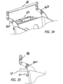
- Figures 29 to 31 and 36 to 38 show different configuration of the support member 58 by which the basket 12 can be attached to the base frame 22 and still achieve the benefits described above.
- the attachment means can be of many different shapes, sizes, location and of any suitable material of sufficient strength and rigidity that the basket portion of the cart does not sink lower than preferred when the cart basket 12 is fully loaded.
- some flexibility may be desired so that it provides a shock absorber or cushioning effect if a child is in the cart seat. As carts are not nested or stacked unless empty, however, any flexibility will not adversely affect that operation.
- the base frame (or shelf) 24 can be square or rectangular to provide even greater carrying capability.
- the relative sizes and relationship of the basket 12 and base frame 24 can adjusted to fit store and/or customer preference for a larger bottom shelf space and more "headroom" in that shelf.
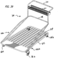
- FIG 39 shows a different type of cart 100 that does not have a basket. Rather this cart 100 is more adapted for use in "big box" stores. It comprises a base frame 102, a base shelf 104 that is preferably constructed of sturdy cross-hatched wire to reduce weight and cost without sacrificing utility. Side struts 106a and 106b extends from the front portion of the base from 102 diagonally upwardly and rearwardly to form a rear bar 108 and a handle 110. In this embodiment, a small wire basket 112 is attached between the struts 106a and 106b to hold smaller items.
- this cart 100 also has front wheels 114a and 114b, and rear wheels 116a and 116b in which the lateral distance between them respectively allows the front wheels to slide over and outside the rear wheels in a nested-cart arrangement, and the front of the base frame 102 is higher in front, and lower in back, to allow the front of the base frame 102 to slide above the back of the base frame 102 in adjacent carts when in a nested arrangement. All this is shown in Figure 42 .
- Figures 43 to 45 show a similar cart, but with a different basket 118. As this clearly shows, any suitable size and shape basket that will fit within the struts 106 can be utilized.
- Figure 46 shows this embodiment of the cart in a multiple-cart nested arrangement.
- Figure 47 shows a similar cart 100, but without any basket.
- the front wheels are not only located “outside” the track of the rear wheels and "outside” the width of the rear portion of the bottom shelf frame, the front wheels are also larger in diameter than the rear wheels. This raises the front of the bottom base (shelf) frame to an elevation that is higher than the rear of the bottom base (shelf) frame.
- the base frame is 3 inches above ground in the front, and only 1 inch above ground in the rear. This is not the only arrangement possible, and many difference arrangements and dimensions are possible.
- the front wheels and the front bottom shelf frame slide easily over and outside of the frame and rear wheels of the cart into which the first cart is being inserted.
- This provides for much easier stacking, which is not only more convenient for the person doing the stacking, but also helps reduce damage to the carts from the stacking operation.
- the stacking operation for traditional carts can sometimes require a significant force that can damage the cart.
- the child seat portion of the cart has been designed in some embodiments to be safer and more comfortable than in the traditional cart.
- the openings in the carts rear panel for the child's legs are larger than typical, and have rounded edges for comfort.
- a child restraining belt (not shown) can be attached to either side of the cart, and each belt can connect to a buckle that extends upwardly between the child's legs. The potential for a momentarily unattended child standing up in the cart (and maybe falling out) is significantly reduced if not eliminated.
- see-through sleeves (not shown) can be added into which advertising or other informational messages can be includes.
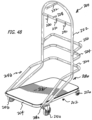
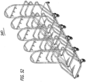
- Figures 48 to 53 show a fully-nesting hotel-type luggage cart 200 in which there is a base 202 that includes a base frame 204 and full, solid-piece floor board 206.
- the base frame 204 and the floor board 206 are rectangular. As will we appreciated, other shapes can be used.
- a pair side flanges 208a and 208b are securely attached to the base frame 204 near the front of the cart 200, and extend laterally outward from the base frame 204 to a position that is wider than the rear portion of the base frame 204.
- a pair of front wheels 210a and 210b are attached respectively to the bottom of side flanges 208a and 208b, and a pair of rear wheels 212a and 212b are respectively attached to the base frame 204 itself at or near the rear corners of the base frame 204.
- this arrangement provides that the distance between the inside rims of the front wheels 210a and 210b is greater than the distance between the outside rims of rear wheels 212a and 212b. This differential distances allows the front wheels 210a and 210b to be able to travel unrestrictedly past the rear wheels 212a and 212b thereby allowing multiple carts 200 to nest together in telescoping fashion as shown in Figure 52 .
- the front and rear portions of the base 202 must have a height differential.
- rear wheels 212a and 212b are smaller in diameter than front wheels 210a and 210b.
- This size differential results in the base 202 being slanted upward toward the front of the cart 200 a sufficient amount such that the bottom portion 214 of the base 202 at the front of the cart 200 is higher than the top portion 216 at the rear of the cart 200.
- This height differential can of course be accomplished by other suitable means, and does not need to be done using wheels of different diameters. Also, it is preferred that at least one set of the wheels is rotatable around their vertical axis, and both sets can be made to do so if that is desired.
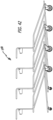
- a pair of struts 218a and 218b are securely attached to the top of side flanges 208a and 208b which are located at or near the front of the base 202.
- the struts 218a and 218b do not need to have two legs and can be of any material and component(s) that provide for sufficient structure rigidity.
- the struts 218a and 218b extend upward diagonally toward the rear of the cart 200, leaving a significant area of the base 202 free of any structure that might preclude proper nesting.
- the legs 220a and 220b of struts 218a and 218b also form a structure at the rear of the cart which comprises crossmember 220 and hoop member 222.
- U-shaped members 224 and 226 extend rearwardly from the hoop member 222. These U-shaped members can act as the handle for the person using the cart 200, and can also be used to store luggage and other personal items.
- a cross bar 228 having hooks 230 extends between the two vertical portion of hoop member 222 to provide additional storage capability, as does rod 232 that extends inwardly toward the front of the cart 200.
- this luggage cart will provide all of the storage and stacking capability of the traditional hotel-type luggage cart, but in a fully-nesting design.
Landscapes
- Engineering & Computer Science (AREA)
- Chemical & Material Sciences (AREA)
- Combustion & Propulsion (AREA)
- Transportation (AREA)
- Mechanical Engineering (AREA)
- Handcart (AREA)
Claims (12)
- Ein Wagen (10) zum Transportieren von Gütern, umfassend:a) einen Rahmen mit mindestens einem vorderen und einem hinteren Teil;b) eine im Wesentlichen flache Plattform (26), die an dem Rahmen befestigt ist und die zusammen mit dem Rahmen eine Grundrahmenstruktur (24) mit einem vorderen Abschnitt, einem hinteren Abschnitt und Seitenabschnitten aufweist; wobei der vordere Abschnitt und der hintere Abschnitt jeweils eine Oberseite und eine Unterseite aufweisen;c) mindestens 4 Räder (38a, 38b, 40a, 40b), die an der Grundrahmenstruktur (24) befestigt sind und sich nach unten erstrecken, um den Boden oder eine andere Oberfläche zu berühren, über die sich der Wagen bewegt, wenn er in Gebrauch ist, wobei die Räder jeweils eine seitliche Innenkante und eine seitliche Außenkante aufweisen, die durch die seitliche Breite der Räder und nicht durch ihren jeweiligen Umfang definiert sind;d) wobei zwei der Räder Vorderräder (38a, 38b) sind, die in der Nähe des vorderen Abschnitts der Grundrahmenstruktur (24) angebracht sind, wobei die beiden Vorderräder im Wesentlichen seitlich nebeneinander ausgerichtet sind, wenn sie von der Seite betrachtet werden, wobei die Vorderräder einen seitlichen Abstand zwischen ihren jeweiligen Innenkanten aufweisen;e) wobei zwei der Räder Hinterräder (40a, 40b) sind, die in der Nähe des hinteren Abschnitts der Grundrahmenstruktur (24) angebracht sind, wobei die beiden Hinterräder im Wesentlichen seitlich nebeneinander ausgerichtet sind, wenn sie von der Seite betrachtet werden, wobei die Hinterräder einen seitlichen Abstand zwischen ihren jeweiligen Außenkanten haben;f) der vordere Abschnitt der Grundrahmenstruktur (24) relativ zu dem hinteren Abschnitt der Grundrahmenstruktur höher ist, so dass, wenn der Wagen (10) in Gebrauch ist, die Grundrahmenstruktur (24) um ein ausreichendes Maß nach unten (relativ zu der Oberfläche) geneigt ist, so dass der untere Abschnitt des vorderen Abschnitts höher ist (relativ zu der Oberfläche) als der obere Abschnitt des hinteren Abschnitts;dadurch gekennzeichnet, dass
die Anordnung, Platzierung, Größe und Form der Vorderräder (38a, 38b) und der Hinterräder (40a, 40b) derart ist, dass der seitliche Abstand zwischen den Kanten der Vorderräder (30a, 38b) größer ist als der seitliche Abstand zwischen den Außenkanten der Hinterräder (40a, 40b). - Wagen nach Anspruch 1, wobei der vordere Teil der Grundrahmenstruktur (24) eines solchen Wagens (10) über den hinteren Teil der Grundrahmenstruktur (24) eines zweiten solchen Wagens (10) um mindestens ein Drittel der Längslänge der Grundrahmenstruktur gleiten kann, um ein teleskopartiges Ineinanderschieben mehrerer solcher Wagen zu ermöglichen.
- Wagen nach Anspruch 1 mit mindestens einer Stützstrebe (28a, 28b), die in der Nähe des vorderen Abschnitts der Grundrahmenstruktur (24) angebracht ist und sich von dort nach oben und hinten erstreckt, und einer korbähnlichen Struktur (12) mit einem vorderen Abschnitt und einem hinteren Abschnitt, an dem die Stützstrebe (28a, 28b) in der Nähe des hinteren Abschnitts angebracht ist, um die korbähnliche Struktur (12) in einer im wesentlichen starren Ausrichtung relativ zu der Grundrahmenstruktur (24) zu halten.
- Wagen nach Anspruch 1, bei dem zwei Stützstreben (28a, 28b) vorhanden sind, eine auf jeder Seite des Wagens.
- Wagen nach Anspruch 2, bei dem zwei Stützstreben (28a, 28b) vorhanden sind, eine auf jeder Seite des Wagens.
- Wagen nach Anspruch 2, bei dem die korbartige Struktur (12) eine solche Größe und Form hat, dass der vordere Teil ausreichend kleiner ist als der hintere Teil, so dass die Außenabmessungen des vorderen Teils geringer sind als die Außenabmessungen des hinteren Teils, wodurch der vordere Teil eines solchen Wagens (10) teleskopartig in den hinteren Teil eines zweiten solchen Wagens (10) passen kann.
- Wagen nach Anspruch 1 mit einer Griffstruktur (48), die an der Grundrahmenstruktur (24) befestigt ist und sich in eine rückwärtige Richtung erstreckt, um vom Benutzer des Wagens zum Schieben und Steuern der Fahrtrichtung des Wagens verwendet zu werden.
- Wagen nach Anspruch 3 mit einer Griffstruktur (48), die an der korbähnlichen Struktur (12) angebracht ist und sich in eine rückwärtige Richtung erstreckt, um vom Benutzer des Wagens zum Schieben und Steuern der Fahrtrichtung des Wagens verwendet zu werden.
- Wagen nach Anspruch 7, bei dem eine korbartige Struktur (12) an der Griffstruktur (48) befestigt ist.
- Wagen nach Anspruch 7, bei dem die Griffstruktur (48) einen drehbaren Abschnitt aufweist, der von dem Benutzer des Wagens in verschiedene Positionen gedreht werden kann.
- Wagen nach Anspruch 1, bei dem eine sich nach oben erstreckende Struktur (52), an der Kleidersäcke, Geldbörsen, Aktentaschen und dergleichen aufgehängt werden können, an dem hinteren Teil der Grundrahmenstruktur (24) befestigt ist.
- Wagen nach Anspruch 11, bei dem die sich nach oben erstreckende Struktur (52) so bemessen und geformt ist, dass die Struktur auf einem solchen Wagen (10) in unmittelbarer Nähe zu der ähnlichen Struktur (52) auf einem zweiten solchen Wagen (10) passen kann, wenn die Wagen teleskopartig ineinander geschoben werden.
Applications Claiming Priority (3)
| Application Number | Priority Date | Filing Date | Title |
|---|---|---|---|
| US201962854835P | 2019-05-30 | 2019-05-30 | |
| US202063100283P | 2020-03-06 | 2020-03-06 | |
| PCT/US2020/000020 WO2020242536A1 (en) | 2019-05-30 | 2020-05-29 | Cart |
Publications (4)
| Publication Number | Publication Date |
|---|---|
| EP3976442A1 EP3976442A1 (de) | 2022-04-06 |
| EP3976442A4 EP3976442A4 (de) | 2023-11-08 |
| EP3976442B1 true EP3976442B1 (de) | 2025-03-12 |
| EP3976442C0 EP3976442C0 (de) | 2025-03-12 |
Family
ID=73552029
Family Applications (1)
| Application Number | Title | Priority Date | Filing Date |
|---|---|---|---|
| EP20813056.7A Active EP3976442B1 (de) | 2019-05-30 | 2020-05-29 | Wagen |
Country Status (4)
| Country | Link |
|---|---|
| US (2) | US11904923B2 (de) |
| EP (1) | EP3976442B1 (de) |
| CA (1) | CA3142276A1 (de) |
| WO (1) | WO2020242536A1 (de) |
Families Citing this family (2)
| Publication number | Priority date | Publication date | Assignee | Title |
|---|---|---|---|---|
| US11904923B2 (en) * | 2019-05-30 | 2024-02-20 | Ryankart, Llc | Cart |
| WO2024000395A1 (en) * | 2022-06-30 | 2024-01-04 | Maplebear Inc. | Shopping cart self-tracking in an indoor environment |
Family Cites Families (13)
| Publication number | Priority date | Publication date | Assignee | Title |
|---|---|---|---|---|
| FR1125063A (fr) * | 1955-04-22 | 1956-10-23 | Chariot de manutention formant balance | |
| US3174768A (en) * | 1963-06-27 | 1965-03-23 | Technibilt Corp | Luggage cart |
| US3437176A (en) * | 1967-01-17 | 1969-04-08 | United Steel & Wire Co | Grocery cart with inclined bottom having a front opening gate system |
| ES2091693T3 (es) * | 1993-04-07 | 1996-11-01 | Wanzl Entwicklung Gmbh | Carro de compra. |
| US8857827B2 (en) * | 2008-09-11 | 2014-10-14 | Shane Chen | Manually driven cart with biased-direction rear wheels |
| US8056909B2 (en) * | 2009-05-01 | 2011-11-15 | Phoenix Intangibles Holding Company | Shopping cart |
| US8814199B2 (en) * | 2010-07-23 | 2014-08-26 | John Oliver Shindelar | Collapsible cart |
| US20150053652A1 (en) * | 2012-12-06 | 2015-02-26 | Unarco Industries Llc | Shopping Cart Basket and Method of Manufacture |
| US20140159327A1 (en) * | 2012-12-06 | 2014-06-12 | Unarco Industries Llc | Shopping Cart |
| DE102014107724A1 (de) * | 2014-06-02 | 2015-12-03 | Wanzl Metallwarenfabrik Gmbh | Transportwagen |
| US9321473B2 (en) * | 2014-07-17 | 2016-04-26 | Technibilt, Ltd | Carrying cart for special needs rider |
| US11332179B2 (en) * | 2019-01-08 | 2022-05-17 | Unarco Industries Llc | Cart |
| US11904923B2 (en) * | 2019-05-30 | 2024-02-20 | Ryankart, Llc | Cart |
-
2020
- 2020-05-29 US US17/615,191 patent/US11904923B2/en active Active
- 2020-05-29 WO PCT/US2020/000020 patent/WO2020242536A1/en not_active Ceased
- 2020-05-29 EP EP20813056.7A patent/EP3976442B1/de active Active
- 2020-05-29 CA CA3142276A patent/CA3142276A1/en active Pending
-
2024
- 2024-01-10 US US18/409,101 patent/US12415556B2/en active Active
Also Published As
| Publication number | Publication date |
|---|---|
| US20240140512A1 (en) | 2024-05-02 |
| EP3976442A1 (de) | 2022-04-06 |
| WO2020242536A1 (en) | 2020-12-03 |
| CA3142276A1 (en) | 2020-12-03 |
| EP3976442C0 (de) | 2025-03-12 |
| US20220227406A1 (en) | 2022-07-21 |
| US11904923B2 (en) | 2024-02-20 |
| US12415556B2 (en) | 2025-09-16 |
| EP3976442A4 (de) | 2023-11-08 |
Similar Documents
| Publication | Publication Date | Title |
|---|---|---|
| US8066291B2 (en) | Shopping cart | |
| US8056909B2 (en) | Shopping cart | |
| US6793223B2 (en) | Convertible stocking cart | |
| US12415556B2 (en) | Cart | |
| RU2415626C2 (ru) | Усовершенствованная штабелируемая корзина | |
| US4733877A (en) | Cart apparatus with improved handle | |
| US7887068B2 (en) | Mutually nestable shopping carts having bag hangers | |
| US8540273B2 (en) | Shopping cart designed for vehicle trunks | |
| NL194790C (nl) | Winkelwagensamenstel voor het transporteren van koopwaar, alsmede winkelwagen, respectievelijk houder hiervoor. | |
| US7681891B2 (en) | Shopping cart adapted to receive elongated items | |
| US7703776B1 (en) | Shopping cart and hand truck and golf bag cart and garden cart | |
| US20120160886A1 (en) | Market Basket System | |
| US20240132130A1 (en) | Shopping cart with lifting fender | |
| CN102653281B (zh) | 婴儿车 | |
| JP2011506176A (ja) | 買った品物を店から車および車から家に運ぶためのショッピングカート | |
| US9840265B1 (en) | Nested luggage cart | |
| US11919558B2 (en) | Shopping trolley | |
| US3240507A (en) | Merchandising cart | |
| US5700021A (en) | Mobile cart | |
| US20130285340A1 (en) | Shopping basket | |
| WO2000034102A1 (en) | Shopping cart | |
| US20120286485A1 (en) | Cart for large area objects | |
| CA3015123A1 (en) | Shopping cart apparatus | |
| FR2700150A1 (fr) | Dispositif de chariot pliable verticalement et horizontalement. | |
| JP3237595U (ja) | ショッピングカート |
Legal Events
| Date | Code | Title | Description |
|---|---|---|---|
| STAA | Information on the status of an ep patent application or granted ep patent |
Free format text: STATUS: THE INTERNATIONAL PUBLICATION HAS BEEN MADE |
|
| PUAI | Public reference made under article 153(3) epc to a published international application that has entered the european phase |
Free format text: ORIGINAL CODE: 0009012 |
|
| STAA | Information on the status of an ep patent application or granted ep patent |
Free format text: STATUS: REQUEST FOR EXAMINATION WAS MADE |
|
| 17P | Request for examination filed |
Effective date: 20211213 |
|
| AK | Designated contracting states |
Kind code of ref document: A1 Designated state(s): AL AT BE BG CH CY CZ DE DK EE ES FI FR GB GR HR HU IE IS IT LI LT LU LV MC MK MT NL NO PL PT RO RS SE SI SK SM TR |
|
| DAV | Request for validation of the european patent (deleted) | ||
| DAX | Request for extension of the european patent (deleted) | ||
| A4 | Supplementary search report drawn up and despatched |
Effective date: 20231011 |
|
| RIC1 | Information provided on ipc code assigned before grant |
Ipc: B62D 39/00 20060101ALI20231005BHEP Ipc: B62B 3/14 20060101AFI20231005BHEP |
|
| GRAP | Despatch of communication of intention to grant a patent |
Free format text: ORIGINAL CODE: EPIDOSNIGR1 |
|
| STAA | Information on the status of an ep patent application or granted ep patent |
Free format text: STATUS: GRANT OF PATENT IS INTENDED |
|
| INTG | Intention to grant announced |
Effective date: 20240717 |
|
| GRAS | Grant fee paid |
Free format text: ORIGINAL CODE: EPIDOSNIGR3 |
|
| GRAA | (expected) grant |
Free format text: ORIGINAL CODE: 0009210 |
|
| STAA | Information on the status of an ep patent application or granted ep patent |
Free format text: STATUS: THE PATENT HAS BEEN GRANTED |
|
| AK | Designated contracting states |
Kind code of ref document: B1 Designated state(s): AL AT BE BG CH CY CZ DE DK EE ES FI FR GB GR HR HU IE IS IT LI LT LU LV MC MK MT NL NO PL PT RO RS SE SI SK SM TR |
|
| REG | Reference to a national code |
Ref country code: GB Ref legal event code: FG4D |
|
| REG | Reference to a national code |
Ref country code: CH Ref legal event code: EP |
|
| REG | Reference to a national code |
Ref country code: DE Ref legal event code: R096 Ref document number: 602020047667 Country of ref document: DE |
|
| REG | Reference to a national code |
Ref country code: IE Ref legal event code: FG4D |
|
| U01 | Request for unitary effect filed |
Effective date: 20250410 |
|
| U07 | Unitary effect registered |
Designated state(s): AT BE BG DE DK EE FI FR IT LT LU LV MT NL PT RO SE SI Effective date: 20250417 |
|
| U20 | Renewal fee for the european patent with unitary effect paid |
Year of fee payment: 6 Effective date: 20250527 |
|
| PG25 | Lapsed in a contracting state [announced via postgrant information from national office to epo] |
Ref country code: RS Free format text: LAPSE BECAUSE OF FAILURE TO SUBMIT A TRANSLATION OF THE DESCRIPTION OR TO PAY THE FEE WITHIN THE PRESCRIBED TIME-LIMIT Effective date: 20250612 |
|
| PG25 | Lapsed in a contracting state [announced via postgrant information from national office to epo] |
Ref country code: ES Free format text: LAPSE BECAUSE OF FAILURE TO SUBMIT A TRANSLATION OF THE DESCRIPTION OR TO PAY THE FEE WITHIN THE PRESCRIBED TIME-LIMIT Effective date: 20250312 |
|
| PG25 | Lapsed in a contracting state [announced via postgrant information from national office to epo] |
Ref country code: NO Free format text: LAPSE BECAUSE OF FAILURE TO SUBMIT A TRANSLATION OF THE DESCRIPTION OR TO PAY THE FEE WITHIN THE PRESCRIBED TIME-LIMIT Effective date: 20250612 |
|
| PG25 | Lapsed in a contracting state [announced via postgrant information from national office to epo] |
Ref country code: HR Free format text: LAPSE BECAUSE OF FAILURE TO SUBMIT A TRANSLATION OF THE DESCRIPTION OR TO PAY THE FEE WITHIN THE PRESCRIBED TIME-LIMIT Effective date: 20250312 |
|
| PG25 | Lapsed in a contracting state [announced via postgrant information from national office to epo] |
Ref country code: GR Free format text: LAPSE BECAUSE OF FAILURE TO SUBMIT A TRANSLATION OF THE DESCRIPTION OR TO PAY THE FEE WITHIN THE PRESCRIBED TIME-LIMIT Effective date: 20250613 |
|
| PG25 | Lapsed in a contracting state [announced via postgrant information from national office to epo] |
Ref country code: SM Free format text: LAPSE BECAUSE OF FAILURE TO SUBMIT A TRANSLATION OF THE DESCRIPTION OR TO PAY THE FEE WITHIN THE PRESCRIBED TIME-LIMIT Effective date: 20250312 |
|
| PG25 | Lapsed in a contracting state [announced via postgrant information from national office to epo] |
Ref country code: PL Free format text: LAPSE BECAUSE OF FAILURE TO SUBMIT A TRANSLATION OF THE DESCRIPTION OR TO PAY THE FEE WITHIN THE PRESCRIBED TIME-LIMIT Effective date: 20250312 |
|
| PGFP | Annual fee paid to national office [announced via postgrant information from national office to epo] |
Ref country code: GB Payment date: 20250820 Year of fee payment: 6 |
|
| PG25 | Lapsed in a contracting state [announced via postgrant information from national office to epo] |
Ref country code: CZ Free format text: LAPSE BECAUSE OF FAILURE TO SUBMIT A TRANSLATION OF THE DESCRIPTION OR TO PAY THE FEE WITHIN THE PRESCRIBED TIME-LIMIT Effective date: 20250312 |
|
| PG25 | Lapsed in a contracting state [announced via postgrant information from national office to epo] |
Ref country code: SK Free format text: LAPSE BECAUSE OF FAILURE TO SUBMIT A TRANSLATION OF THE DESCRIPTION OR TO PAY THE FEE WITHIN THE PRESCRIBED TIME-LIMIT Effective date: 20250312 |
|
| PG25 | Lapsed in a contracting state [announced via postgrant information from national office to epo] |
Ref country code: IS Free format text: LAPSE BECAUSE OF FAILURE TO SUBMIT A TRANSLATION OF THE DESCRIPTION OR TO PAY THE FEE WITHIN THE PRESCRIBED TIME-LIMIT Effective date: 20250712 |
|
| REG | Reference to a national code |
Ref country code: CH Ref legal event code: H13 Free format text: ST27 STATUS EVENT CODE: U-0-0-H10-H13 (AS PROVIDED BY THE NATIONAL OFFICE) Effective date: 20251223 |
|
| PLBE | No opposition filed within time limit |
Free format text: ORIGINAL CODE: 0009261 |
|
| STAA | Information on the status of an ep patent application or granted ep patent |
Free format text: STATUS: NO OPPOSITION FILED WITHIN TIME LIMIT |
|
| PG25 | Lapsed in a contracting state [announced via postgrant information from national office to epo] |
Ref country code: CH Free format text: LAPSE BECAUSE OF NON-PAYMENT OF DUE FEES Effective date: 20250531 |
|
| REG | Reference to a national code |
Ref country code: CH Ref legal event code: L10 Free format text: ST27 STATUS EVENT CODE: U-0-0-L10-L00 (AS PROVIDED BY THE NATIONAL OFFICE) Effective date: 20260121 |
|
| PG25 | Lapsed in a contracting state [announced via postgrant information from national office to epo] |
Ref country code: MC Free format text: LAPSE BECAUSE OF FAILURE TO SUBMIT A TRANSLATION OF THE DESCRIPTION OR TO PAY THE FEE WITHIN THE PRESCRIBED TIME-LIMIT Effective date: 20250312 |