EP3976352B1 - Zahnärztliches gerät zur behandlung von bruxismus und schlafapnoe - Google Patents
Zahnärztliches gerät zur behandlung von bruxismus und schlafapnoe Download PDFInfo
- Publication number
- EP3976352B1 EP3976352B1 EP20814236.4A EP20814236A EP3976352B1 EP 3976352 B1 EP3976352 B1 EP 3976352B1 EP 20814236 A EP20814236 A EP 20814236A EP 3976352 B1 EP3976352 B1 EP 3976352B1
- Authority
- EP
- European Patent Office
- Prior art keywords
- patient
- sublingual
- dental appliance
- feature
- palatal
- Prior art date
- Legal status (The legal status is an assumption and is not a legal conclusion. Google has not performed a legal analysis and makes no representation as to the accuracy of the status listed.)
- Active
Links
Images













Classifications
-
- A—HUMAN NECESSITIES
- A61—MEDICAL OR VETERINARY SCIENCE; HYGIENE
- A61F—FILTERS IMPLANTABLE INTO BLOOD VESSELS; PROSTHESES; DEVICES PROVIDING PATENCY TO, OR PREVENTING COLLAPSING OF, TUBULAR STRUCTURES OF THE BODY, e.g. STENTS; ORTHOPAEDIC, NURSING OR CONTRACEPTIVE DEVICES; FOMENTATION; TREATMENT OR PROTECTION OF EYES OR EARS; BANDAGES, DRESSINGS OR ABSORBENT PADS; FIRST-AID KITS
- A61F5/00—Orthopaedic methods or devices for non-surgical treatment of bones or joints; Nursing devices ; Anti-rape devices
- A61F5/56—Devices for preventing snoring
- A61F5/566—Intra-oral devices
-
- B—PERFORMING OPERATIONS; TRANSPORTING
- B29—WORKING OF PLASTICS; WORKING OF SUBSTANCES IN A PLASTIC STATE IN GENERAL
- B29C—SHAPING OR JOINING OF PLASTICS; SHAPING OF MATERIAL IN A PLASTIC STATE, NOT OTHERWISE PROVIDED FOR; AFTER-TREATMENT OF THE SHAPED PRODUCTS, e.g. REPAIRING
- B29C64/00—Additive manufacturing, i.e. manufacturing of three-dimensional [3D] objects by additive deposition, additive agglomeration or additive layering, e.g. by 3D printing, stereolithography or selective laser sintering
- B29C64/30—Auxiliary operations or equipment
- B29C64/386—Data acquisition or data processing for additive manufacturing
-
- B—PERFORMING OPERATIONS; TRANSPORTING
- B33—ADDITIVE MANUFACTURING TECHNOLOGY
- B33Y—ADDITIVE MANUFACTURING, i.e. MANUFACTURING OF THREE-DIMENSIONAL [3D] OBJECTS BY ADDITIVE DEPOSITION, ADDITIVE AGGLOMERATION OR ADDITIVE LAYERING, e.g. BY 3D PRINTING, STEREOLITHOGRAPHY OR SELECTIVE LASER SINTERING
- B33Y50/00—Data acquisition or data processing for additive manufacturing
-
- B—PERFORMING OPERATIONS; TRANSPORTING
- B33—ADDITIVE MANUFACTURING TECHNOLOGY
- B33Y—ADDITIVE MANUFACTURING, i.e. MANUFACTURING OF THREE-DIMENSIONAL [3D] OBJECTS BY ADDITIVE DEPOSITION, ADDITIVE AGGLOMERATION OR ADDITIVE LAYERING, e.g. BY 3D PRINTING, STEREOLITHOGRAPHY OR SELECTIVE LASER SINTERING
- B33Y80/00—Products made by additive manufacturing
-
- G—PHYSICS
- G16—INFORMATION AND COMMUNICATION TECHNOLOGY [ICT] SPECIALLY ADAPTED FOR SPECIFIC APPLICATION FIELDS
- G16H—HEALTHCARE INFORMATICS, i.e. INFORMATION AND COMMUNICATION TECHNOLOGY [ICT] SPECIALLY ADAPTED FOR THE HANDLING OR PROCESSING OF MEDICAL OR HEALTHCARE DATA
- G16H50/00—ICT specially adapted for medical diagnosis, medical simulation or medical data mining; ICT specially adapted for detecting, monitoring or modelling epidemics or pandemics
- G16H50/50—ICT specially adapted for medical diagnosis, medical simulation or medical data mining; ICT specially adapted for detecting, monitoring or modelling epidemics or pandemics for simulation or modelling of medical disorders
-
- A—HUMAN NECESSITIES
- A61—MEDICAL OR VETERINARY SCIENCE; HYGIENE
- A61F—FILTERS IMPLANTABLE INTO BLOOD VESSELS; PROSTHESES; DEVICES PROVIDING PATENCY TO, OR PREVENTING COLLAPSING OF, TUBULAR STRUCTURES OF THE BODY, e.g. STENTS; ORTHOPAEDIC, NURSING OR CONTRACEPTIVE DEVICES; FOMENTATION; TREATMENT OR PROTECTION OF EYES OR EARS; BANDAGES, DRESSINGS OR ABSORBENT PADS; FIRST-AID KITS
- A61F5/00—Orthopaedic methods or devices for non-surgical treatment of bones or joints; Nursing devices ; Anti-rape devices
- A61F5/56—Devices for preventing snoring
- A61F2005/563—Anti-bruxisme
-
- B—PERFORMING OPERATIONS; TRANSPORTING
- B29—WORKING OF PLASTICS; WORKING OF SUBSTANCES IN A PLASTIC STATE IN GENERAL
- B29L—INDEXING SCHEME ASSOCIATED WITH SUBCLASS B29C, RELATING TO PARTICULAR ARTICLES
- B29L2031/00—Other particular articles
- B29L2031/753—Medical equipment; Accessories therefor
Definitions
- This invention relates to a method and a dental appliance for treating bruxism, sleep apnea, or combinations thereof.
- Bruxism can cause irreversible damage to teeth and the temporomandibular joint (TMJ).
- TMJ temporomandibular joint
- bruxism may contribute to a temporomandibular disorder (TMD).
- TMD temporomandibular disorder
- Bruxism can contribute to sleep problems.
- Sleep apnea is a sleep disorder typically characterized by pauses in breathing. These pauses cause carbon dioxide to build up in the bloodstream. In response to this build-up, the brain wakes the person from sleeping. Once awake, normal breathing may resume and the person may fall asleep again. However, the interruption, or a series of such interruptions may prevent the person from getting adequate rest. This may in turn produce daytime fatigue, a slower reaction time, vision problems, an increased risk of diabetes, and the like. Accordingly, what is needed is an apparatus and method for preventing bruxism and/or sleep apnea and the negative consequences thereof.
- WO 2019/034742A1 discloses a system and method of manufacturing a mouth piece by 3D printing a 3D printer readable file encoding the mouth piece, the method comprising steps of: obtaining a scan file comprising physical date representing a user's teeth and gum line using 3D scanner means (100); removing outlier-data from physical date in the scan file; generating representative geometrical data of the curvature of the user's teeth and gum line from the physical data; generating a virtual base model representing a mouth piece from the physical data and the representative geometrical data, the virtual base model having customizable dimensions (101); removing selected regions from the mouth piece represented by the virtual base model (102); and from the virtual base model, generating the 3D printer readable file encoding the mouth piece for printing on 3D printing means (103).
- US Patent No. 5,682,903 is considered to be the closest prior art document for claim 6. It discloses an apparatus for intra-oral use including a framework having an upper curved platform and a lower curved platform, each of the platforms being defined by two walls extending from and separated by a floor, a material bonded to the upper and lower curved platform adapted to be molded in a shape suitable for relatively snugly receiving maxillary teeth of a user and for relatively loosely receiving mandibular teeth of the user when the user's mouth is closed in a normal closing arch, and a cavity formed between the upper and lower platforms adapted to receive the tongue of the user.
- US Patent No. 4,304,227 discloses a device for positioning within the mouth of a user for preventing snoring and nocturnal tooth grinding.
- the device is an integrally molded body.
- the device provides dental engaging portions and a rearwardly-opening central socket for cooperating with the forward portion of the user's tongue in a manner to draw the tongue forwardly so as to increase the unobstructed dimension of the nasal breathing passage.
- some of the user's upper and lower teeth will enter into recesses provided by the device.
- the device substantially eliminates oral breathing.
- the tongue will be held in the socket by a negative pressure developed in the socket.
- the tongue When the tongue is held, it draws the body of the tongue forwardly of its usual restive position behind the lower teeth and adjacent the soft palate, the uvula and the posterior pharyngeal wall, thereby increasing the dimension of the air flow passage through the nasopharynx to facilitate nasal breathing.
- the device's engagement with at least portions of one of the user's dental arches operates to eliminate nocturnal tooth- grinding.
- WO 2011/060103 discloses an automated tissue retention system generally comprising an oral appliance retractably coupled to a covering which is secured to an anterior portion of the tongue. Once placed within a subject's mouth, the appliance may be maintained in a closed configuration while the subject's mouth remains closed. However, as the subject sleeps and the tongue becomes hypotonic, the subject's mouth typically opens during a sleep disordered event. The appliance may be actuated by the separation between the mandible and maxilla to have greater tension and thus retract or pull anteriorly the covering adhered to the tongue. As the covering pulls the tongue anteriorly or maintains a position of the tongue, the base of the tongue may be inhibited or prevented from collapsing posteriorly against the phryngeal tissue walls and thereby allow the subject to breathe normally.
- a method and apparatus are disclosed in one embodiment of the present invention as including a dental appliance having or providing a tongue-retention feature.
- the appliance may comprise a base custom formed to engage the upper (i.e., maxillary) teeth of a patient and a tongue-retention feature formed by one or more structures extending from the base.
- a tongue-retention feature may engage a tongue of a patient so as to hold the tongue in a forward position within the mouth of the patient.
- a tongue-retention feature may prevent a tongue from falling back within the mouth of a patient and inhibiting breathing. Accordingly, a tongue-retention feature may enable an appliance to combat sleep apnea.
- a tongue-retention feature may be a cavity into which a patient may insert his or her tongue. As a tongue is inserted within the cavity, the air therewithin may be expelled. Accordingly, when a tongue is fully seated within the tongue-retention feature, the moist exterior of the tongue may interact with an interior surface of the cavity to create a suction effect resisting extraction of the tongue therefrom. In this manner, a tongue-retention feature may assist in holding a tongue in a forward position until the suction effect is intentionally broken.
- a tongue retention feature is formed or defined by a sublingual portion and a palatal portion.
- the sublingual portion and the palatal portion cooperate to form a cavity for receiving an anterior portion of a tongue.
- bruxism may cause unnecessary muscle strain, tension, and pain.
- jaw muscles may be contracted and strained for extended periods of time.
- grinding and clenching of teeth may cause muscle strain and tension in other areas.
- bruxism may produce muscle strain, tension, and pain in the muscles of the neck.
- Bruxism may cause sleep problems as well.
- headaches may be a symptom of bruxism.
- an appliance 10 in accordance with the present invention may cure a host of ailments.
- an appliance 10 may protect teeth from harmful abrasion and unnecessary wear.
- An appliance 10 may also reduce inflammation of the periodontal ligament (PDL), reduce pulpitis of the teeth, preserve an orthodontic tooth position, reduce muscle strain, tension, and pain in the muscles of the jaw, reduce muscle strain, tension, and pain in the muscles of the neck, enable a user to enter deeper levels of sleep, and/or reduce headaches.
- PDL periodontal ligament
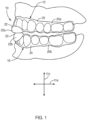
- an appliance 10 may be described in terms of a longitudinal direction 11a, lateral direction 11b, and transverse direction 11c.
- the longitudinal, lateral, and transverse directions 11a, 11b, 11c may extend orthogonally with respect to one another.
- an appliance 10 in accordance with the present invention may include an upper portion 12 corresponding to (e.g., engaging, covering, being worn over) one or more upper or maxillary teeth 14 of a patient and a lower portion 16 corresponding to (e.g., engaging, covering, being worn over) one or more lower or mandibular teeth 18 of the patient.
- the upper and lower portions 12, 16 of an appliance 10 may be worn simultaneously.
- An appliance 10 may cover all of the teeth of a patient or some subset thereof.
- an upper portion 12 may engage or cover all or substantially all maxillary teeth 14 of a patient and a lower portion 16 may engage or cover all or substantially all mandibular teeth 18 of the patient. This may allow for orthodontic retention, product delivery (e.g., application of a whitening product to the teeth), or the like or a combination thereof.
- one or both of an upper portion 12 and a lower portion 16 may respectively cover less than (e.g., substantially less than) all of the maxillary and mandibular teeth of a patient.
- upper and lower portions 12, 16 in accordance with the present invention may each include a base 20 and a feature 22.
- an upper portion 12 may include a first base 20a and a first feature 22a
- a lower portion 16 may include a second base 20b and a second feature 22b.
- a base 20 may be shaped to selectively engage one or more teeth of a patient.
- a feature 22 may be secured to a base 20.
- a base 20 may interface between a feature 22 and certain teeth of a patient.
- a base 20 may be custom made to closely fit certain teeth of a patient. Accordingly, when the base 20 is applied to the one or more teeth, the base 20 may tend to stay there by mechanical gripping, suction, or the like or some combination thereof.
- a corresponding feature 20 may be held in a desired orientation or position with respect to the teeth. However, the base 20 and corresponding feature 22 may be removed from the patient by simply pulling the base 20 away from the corresponding teeth.
- an appliance 10 may include features 22 positioned opposite one another.
- a first feature 22a of an upper portion 12 may be positioned opposite a second feature 22b of a lower portion 16. Accordingly, mandibular motion of a patient (e.g., biting down) may result in a first feature 22a contacting a second feature 22b.
- features 22 may be positioned and shaped to interface or interact with one another in a particular manner.
- a first feature 22a may comprise an indentation 24 or recess 24 and a second feature 22b may comprise a protrusion 26 or mound 26.
- a first feature 22a may comprise a protrusion 26 or mound 24 and a second feature 22b may comprise an indentation 24 or recess 24.
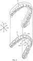
- Figures 1-3 show an indentation 24 forming part of an upper portion 12 and a protrusion 26 forming part of a lower portion 16, in other embodiments, a protrusion 26 may form part of an upper portion 12 and an indentation 24 may form part of a lower portion 16.
- features 22 may be positioned and shaped to interface or interact with one another to control, direct, or influence the mandibular motion, mandibular loadings, or the like of a corresponding patient.
- opposing first and second features 22a, 22b may be located on or secured to anterior areas of the respective first and second bases 20a, 20b.
- the first and second features 22a, 22b may be shaped, sized, or position such that contact therebetween may be or comprise an initial, primary, or exclusive point of contact for forces of occlusion (e.g., biting loads) or the like passing form mandibular teeth to maxillary teeth of the corresponding patient.
- forces of occlusion e.g., biting loads
- an appliance 10 may cause all forces of occlusion to be directed to the front of the mouth or to the front teeth (e.g., maxillary central incisors, maxillary lateral incisors, mandibular central incisors, mandibular lateral incisors, or the like or combinations or sub-combinations thereof).
- the brain of a patient may not allow the muscles of mastication to produce the same force of occlusion when pressure is only on the front teeth. That is, an appliance 10 may not allow the muscles around the joint to contract at full strength.
- an appliance may 10 may prevent a patient from clenching or grinding teeth and provide to the patient the benefits associated therewith.
- An appliance 10 in accordance with the present invention may be manufactured in any suitable manner.
- a base 20 and corresponding feature 22 may be made as a monolithic unit by three-dimensional printing, photo-activation, machining, casting, molding, or the like.
- impressions e.g., actual or digital impressions
- Polymeric material e.g., acrylic sheets
- the bases 20 may be custom made to closely fit selected teeth of a patient. Once the bases 20 are formed, appropriate features 22 may be applied thereto.
- Features 22 in accordance with the present invention may be manufactured from any suitable material or combinations of materials. Suitable materials may include polymers, ceramics, metals, metal alloys, or the like. In certain embodiments, features 22 be manufactured as separate, standardized pieces. That is, while a base 20 may be custom made to fit only one patient, a feature 22 may be an "off-the-shelf" item that may be applied to various bases 20. For example, features 22 may be manufactured in one size or in a relative small set of sizes (e.g., small, medium, large, etc.). Then, once a base 20 has been made, an appropriate feature 22 may be selected, positioned, and bonded to an anterior area of the base 20. Alternatively, a feature 22 may be formed by hand from a polymeric material, epoxy, or the like that is molten, in a softened condition, uncured, or the like and urged against or otherwise bonded to a base 20.
- a feature 22a corresponding to an upper portion 12 may be positioned differently than a feature 22b corresponding to a lower portion 16. This difference may ensure that the two features 22a, 22b properly align when a lower jaw of the corresponding patient is in a desired position (e.g., a neutral, central, forward, lower, or mouth-slightly-open position, or a combination or sub-combination thereof).
- This desired position may be selected to control jaw position and postural muscles of the neck and head to open the airway of the patient, thereby decreasing snoring and reducing the incidence or symptoms of sleep apnea.
- a feature 22a corresponding to an upper portion 12 may be positioned primarily or largely posterior and/or inferior to the maxillary central incisors, while a feature 22b corresponding to a lower portion 16 may be positioned primarily or largely superior (and possible anterior or posterior to) the mandibular central incisors.
- a feature 22 providing or comprising an indentation 24 or recess 24 may have any suitable configuration.
- such a feature 22 may include a first side having a concave surface 28 forming a concavity, which concavity may be the indentation 24 or recess 24.
- the feature 22 may also include a second side having a channel 30 facilitating securement of the feature 22 to a base 20.
- a channel 30 may provide a location for bonding material to be applied to a feature 22 before the feature 22 is applied to a corresponding base 20.
- an aperture 30 or channel 30 may include one or more curved surfaces 32 that track or loosely follow a typical curve associated with an anterior area of a base 20. That is, as a base 20 may curve to accommodate the natural positioning of the incisors, cuspids, bicuspids, etc. of the patient, so a channel 30 or curved surface 32 thereof may curve to accommodate the shape of the base 20. Accordingly, the curved surface 32 may facilitate positioning and stabilizing of a feature 22 with respect to a corresponding base 20.
- a channel 30 may divide a feature 22 into an anterior portion 34 and a posterior portion 36.
- an anterior portion 34 When connected to a base 20 and applied to a patient, an anterior portion 34 may be largely or exclusively positioned anterior to the teeth (e.g., incisors, cuspids, etc.) of the patient.
- a posterior portion 36 When connected to a base 20 and applied to a patient, a posterior portion 36 may be positioned largely or exclusively posterior to those teeth.
- one curved surface 32a or side of a channel 30 may be part of an anterior portion 34, while another, opposite curved surface 32b or side of the channel 30 may be part of a posterior portion 36.
- a channel 30 may have any suitable width in the longitudinal direction 11a between such opposing surfaces 32a, 32b.
- a channel 30 may have a width just wide enough to accommodate the outer or exposed portions of the incisors (or the incisors and cuspids) and the thickness of the base 20 extending thereover.
- a channel 30 may have a width that significantly wider than the teeth corresponding thereto.
- a channel 30 may have one curved surface 32a that tracks or loosely follows the curvature of the anterior side of the teeth, while an opposing curved surface 32b extends posteriorly away from a posterior side of the teeth.
- the wide channel 30 may increase the stability with which the feature 22 may be secured to a base 20. Such stability may be helpful when a feature 22 comprises an indentation 24 or recess 24 positioned largely or entirely posterior to the corresponding teeth.
- the width in the longitudinal direction 11a between opposing surfaces 32 of a channel 30 may be substantially constant across a feature 22 in the lateral direction 11b. That is, the width of the channel 30 may be substantially constant from one end of the channel 30 to the other. Alternatively, the width may vary.
- a channel 30 may have the smallest width at the lateral 11b extremes thereof.
- the channel 30 may be the widest at a middle portion thereof.
- curvature of the opposing surfaces 32 of a channel 30 may be complementary or track one another. For example, if a curved surface 32a corresponding to an anterior portion 34 of a feature 22 is primarily concave, then an opposing curved surface 32b corresponding to a posterior portion 36 of the feature 22 may be primarily convex. Alternatively, curvature of the opposing surfaces 32 of a channel 30 may be substantially opposite. For example, if a curved surface 32a corresponding to an anterior portion 34 of a feature 22 is primarily concave, then an opposing curved surface 32b corresponding to a posterior portion 36 of the feature 22 may also be primarily concave and extend away from the other surface 32a.
- a channel 30 may have any suitable floor 38 or ceiling 38 connecting the opposing curved surfaces 32 or sides.
- a floor 38 or ceiling 38 may be substantially flat.
- a floor 38 or ceiling 38 may be curved (e.g., smoothly curving and transitioning from one curved surface 32a to the opposing curved surface 32b).
- a feature 22 corresponding to an indentation 24 or recess 24 may have a channel 30 with a floor 38 or ceiling 38 that is substantially flat
- a feature 22 corresponding to a protrusion 26 or mound 26 may have a channel 30 with a floor 38 or ceiling 38 that is smoothly curved as it transitions from one curved surface 32a to the opposing curved surface 32b.
- the various edges and surfaces of a feature 22 may be radiused and smooth. Smooth, radiused edges and smooth surfaces may enhance the comfort experienced by a patient in wearing an appliance 10 in accordance with the present invention.
- an upper lip of a patient may rest on an anterior portion 34 of a feature 22 of an upper portion 12 of an appliance 10. Accordingly, the anterior portion 34 may be radiused and smooth to avoid irritating or harming the tender tissues on the interior of the upper lip.
- the tip of a tongue of a patient may rest on a posterior portion 36 of a feature 22 of an upper portion 12 of an appliance 10. Accordingly, the posterior portion 34 may be radiused and smooth to avoid irritating or harming the tongue of the patient.
- a feature 22 providing or comprising a protrusion 26 or mound 26 may have any suitable configuration.
- such a feature 22 may include a first side having a convex surface 40 forming the protrusion 26 or mound 26.
- the feature 22 may also include a second side having an aperture 30 or channel 30 facilitating securement of the feature 22 to a base 20.
- such an aperture 30 or channel 30 may include one or more curved surfaces 32 that track or loosely follow a typically curve associated with an anterior area of a base 20.
- features 22 may change a position of a lower jaw of a patient. For example, when lateral excursions (e.g., when a lower jaw moves side to side in the lateral direction 11b) take place, opposing features 22 may lessen the strain in the TMJ. That is, when directly contacting and opposing one another, the opposing features 22 may maintain a certain initial separation 42 between an upper and lower jaw. However, during a lateral excursion, a protrusion 26 may pass or move out of alignment with an opposing indentation 26. That is, a protrusion 26 may move along and "climb" the walls of an indentation 24. In a laterally misaligned position, a new, greater separation 44 between an upper and lower jaw may be applied or enforced. In certain embodiments or with certain patients, this greater separation 44 in a lateral excursion may lower the strain imposed on the TMJ.
- lateral excursions e.g., when a lower jaw moves side to side in the lateral direction 11b
- opposing features 22 may lessen the
- a protrusion 26 may pass or move out of alignment with an opposing indentation 24.
- a longitudinal excursion may cause a protrusion 26 may move along and "climb" the walls of an indentation 24. Accordingly, in a longitudinally misaligned position, a new, greater separation 44 between an upper and lower jaw may also be applied or enforced.
- a protrusion 26 and indentation 24 in accordance with the present invention may have any suitable fit or relative size therebetween.
- a protrusion 26 may be significantly thinner than an opposing indentation 24 in the longitudinal direction 11a, the lateral direction 11b, or both the longitudinal and lateral directions 11a, 11b.
- a protrusion 26 may move within an opposing indentation 24 through a sizable range of motion in the longitudinal direction 11a, the lateral direction 11b, or both the longitudinal and lateral directions 11a, 11b, respectively.
- a protrusion 26 may be closer to the size of an opposing indentation 24 in the longitudinal direction 11a, the lateral direction 11b, or both the longitudinal and lateral directions 11a, 11b. In such embodiments, a protrusion 26 may move within the indentation 24 through a smaller range of motion in the longitudinal direction 11a, the lateral direction 11b, or both the longitudinal and lateral directions 11a, 11b, respectively. In certain embodiments, a protrusion 26 may substantially match the size of an opposing indentation 24 in one or both of the longitudinal and lateral directions 11a, 11b. Thus, longitudinal and/or lateral excursions may only be permitted to the extent that the protrusion 26 exits the opposing indentation 24.
- the relative sizing and shapes of a protrusion 26 and opposing indentation 24 may define to a certain degree the range of motion of a lower jaw with respect to an upper jaw. Additionally, in selected embodiments, the relative sizing and shapes of a protrusion 26 and opposing indentation 24 may define or generate a biasing force urging a lower jaw into a particular alignment (e.g., a neutral and/or centered alignment) with an upper jaw. For example, the sides of an indentation 24 may bias an opposing protrusion 26 toward a center of the indentation 24.
- each feature 22 and the surfaces 28, 40 thereof may extend gradually and smoothly from the surrounding area of the respective portions 12, 16. Accordingly, in such embodiments, when in contact with one another, opposing features 22 may move smoothly over one another (e.g., in lateral excursions, longitudinal excursions, or both lateral and longitudinal excursions).
- Indentations 24 and protrusions 26 may have any suitable depth 48 and height 50, respectively.
- the depth 48 of a particular indentation 24 may be less than or substantially equal to the height 50 of a corresponding protrusion 26.
- the height 50 of a protrusion 26 may be in a range from about 1 mm to about 12 mm and preferably from about 3 mm to about 8 mm.
- the depth 48 of an indentation 24 may also be in a range from about 1 mm to about 12 mm and preferably from about 3 mm to about 8 mm.
- indentations 24 and protrusions 26 may have any suitable base widths 52, 54, respectively.
- the base width 52 of a particular indentation 24 in both the longitudinal and lateral directions 11a, 11b may be greater than or substantially equal to the base width 54 of a corresponding protrusion 26 in both the longitudinal and lateral directions 11a, 11b.
- the base width 54 of a protrusion 26 in the lateral direction 11b may be in a range from about 2 mm to about 15 mm and preferably from about 5 mm to about 10 mm.
- the base width 52 of an indentation 24 in the lateral direction 11b may be in a range from about 3 mm to about 30 mm and preferably from about 10 mm to about 20 mm.
- the base width 54 of a protrusion 26 in the longitudinal direction 11a may be less than the base width 52 of an indentation 24 in the lateral direction 11b.
- the base width 54 of a protrusion 26 in the longitudinal direction 11a may be in a range from about 2 mm to about 12 mm and preferably from about 5 mm to about 8 mm.
- the base width 52 of an indentation 24 in the longitudinal direction may be in a range from about 3 mm to about 20 mm and preferably from about 8 mm to about 15 mm.
- an appliance 10 may include two opposing protrusions 26 or mounds 26, one on the anterior section of each portion 12, 16.
- opposing protrusions 26 on the anterior sections of the upper and lower portions 12, 16 may form an initial, primary, or exclusive point of contact between an upper jaw and a lower jaw. This may cause all forces of occlusion to be directed to the front of the mouth or to the front teeth and, therefore, prevent a patient from clenching or grinding teeth and provide to the patient the benefits associated therewith.
- opposing protrusions 26 may change a position of a lower jaw. For example, when lateral excursions take place, opposing protrusions 26 may lessen the strain in the TMJ. That is, when directly contacting and opposing one another, two protrusions 26 may maintain a certain initial separation 56 between an upper and lower jaw. However, during a lateral excursion, one protrusion 26a may pass or move out of alignment with the other protrusion 26b. That is, one protrusion 26a may slide off of the other protrusion 26b. In a misaligned position, a new, lower separation 58 between an upper and lower jaw may be allowed or permitted. In certain embodiments or applications, or with certain patients, a lower separation 58 may lower the strain imposed on the TMJ in a lateral excursion.
- one protrusion 26a may pass or move out of alignment with the other protrusion 26b. In a misaligned position, a new, lower separation 58 between an upper and lower jaw may be allowed or permitted. Alternatively, one or both protrusions 26 may be formed such that longitudinal excursions produce no new or lower separation 58 between an upper and lower jaw.
- each protrusion 26 may extend gradually and smoothly from the surrounding area of the respective portions 12, 16. Accordingly, in such embodiments, when in contact with one another, opposing protrusions 26 may move smoothly over one another (e.g., in lateral excursions, longitudinal excursions, or both lateral and longitudinal excursions).
- Protrusions 26 may have any suitable height 60.
- opposing protrusions 26a, 26b may have different heights 60a, 60b.
- the heights 60a, 60b of the opposing protrusions 26a, 26b may be equal.
- the height 60 of each protrusion 26 may be in a range from about 1 mm to about 6 mm and preferably from about 3 mm to about 6 mm.
- the width (e.g., base width) of each protrusion 26 may be in a range from about 5 mm to about 20 mm and preferably from about 10 mm to about 15 mm.
- An appliance 10 with opposing protrusions 26 may be manufactured in any suitable manner.
- impressions of a patient's teeth may be taken, models of patient's teeth may be fabricated, and then polymeric material (e.g., acrylic sheets) may be applied to and/or formed around the modeled teeth to form appropriate bases 20.
- Protrusions 26 may then be positioned appropriately and bonded to the bases 20 on the anterior area thereof.
- Bonding a protrusion 26 to a base 20 may be done by bonding on a feature 22 manufactured as separate, standardized piece.
- a feature 22 and corresponding protrusion 26 may be formed by hand from a polymeric material, epoxy, or the like that is molten, in a softened condition, uncured, or the like and urged against or otherwise bonded to a base 20.
- a protrusion 26a corresponding to an upper portion 12 may be positioned differently than a protrusion 26b corresponding to a lower portion 16. This difference may ensure that the two protrusions 26a, 26b properly align when a lower jaw is in a desired position (e.g., a neutral position).
- a protrusion 26a corresponding to an upper portion 12 may be positioned primarily behind the maxillary central incisors, while a protrusion 26b corresponding to a lower portion 16 may be positioned primarily over or just slightly behind the mandibular central incisors.
- an appliance 10 in accordance with the present invention may be beneficially used by a patient suffering from bruxism, sleep apnea, or both bruxism and sleep apnea.
- an appliance 10 may include a first feature 22a comprising an indentation 24 or recess 24 and a second feature 22b comprising a protrusion 26 or mound 26.
- a first feature 22a may comprise a protrusion 26 or mound 24 and a second feature 22b may comprise an indentation 24 or recess 24.
- Interaction of such features 22a, 22b may be helpful in treating bruxism, sleep apnea, or both bruxism and sleep apnea.
- such features 22a, 22b may be located on or secured to anterior areas of the respective first and second bases 20a, 20b.
- the first and second features 22a, 22b may be shaped, sized, or position such that contact therebetween may be or comprise an initial, primary, or exclusive point of contact for forces of occlusion or the like passing from mandibular teeth to maxillary teeth of the corresponding patient.
- an appliance 10 may cause all forces of occlusion to be directed to the front of the mouth or to the front teeth.
- the brain of a patient may not allow the muscles of mastication to produce the same force of occlusion when pressure is only on the front teeth.
- an appliance may 10 may prevent a patient from clenching or grinding teeth and provide to the patient the benefits associated therewith.
- such features 22a, 22b may urge a lower jaw to a position that reduces the incidence of sleep apnea. That is, interaction or nesting of the complementary concave and convex surfaces the features 22a, 22b and the centering forces 46 associated therewith may bias or guide a lower jaw of the corresponding patient to a desired position. As noted above, this desired position may be selected to open the airway of the patient, thereby decreasing snoring and reducing the incidence or symptoms of sleep apnea.
- an appliance 10 in accordance to the present invention to treat sleep apnea may be enhanced through the addition of one or more biasing members 62.
- a biasing member 62 may apply a force to a lower jaw of a patient.
- the biasing member 62 may be oriented such that the force applied thereby may tend to maintain a protrusion 26 properly centered within an opposing indentation 24.
- a biasing member 62 may assist opposing features 22a, 22b in maintaining the lower jaw of the patient in the desired position.
- a biasing member 62 in accordance with the present invention may have any suitable shape and composition.
- a biasing member 62 may be formed of an elastomeric material. In such embodiments, when a biasing member 62 is stretched from its neutral position, a return or restorative force may be generated and used to maintain the lower jaw of the patient in the desired position.
- a biasing member 62 may apply a force to a lower jaw of a patient by applying a force to a lower portion 16 worn by the patient.
- a biasing member 62 may extend from an upper portion 12 worn by the patient to a lower portion 16 worn by the patient.
- a biasing member 62 may connect to the upper and lower portions 12, 16 in any suitable manner.
- the upper and lower portions 12, 16 may include engagement mechanisms 64 extending to engage one or more biasing members 62.
- An engagement mechanism 64 may have any suitable configuration.
- the configuration of one or more engagement mechanisms 64 may be dictated by the configuration of one or more biasing members 62 corresponding thereof.
- a biasing member 62 may include one or more (e.g., a series of) apertures 66.
- an engagement mechanism 64 may comprise an extension 68 (e.g., a post, hook, or the like) that may extend into an aperture 66, one end of an aperture 66, or the like to engage the corresponding biasing member 62.
- the edges of such an extension 68 may be chamfered, rounded, or the like to reduce or prevent any irritation or injury to the interior of the patient's mouth.
- An engagement mechanism 64 may be connected to a corresponding upper or lower portion 12, 16 in any suitable manner.
- an engagement mechanism 64 e.g., an extension 68
- an engagement mechanism 64 may monolithically formed as part of a base 20, feature 22, or the like.
- an engagement mechanism 64 e.g., extension 68
- an engagement mechanism 64 may be bonded onto a base 20, feature 22, or the like.
- an engagement mechanism 64 may include one or more features facilitating such bonding.
- an engagement mechanism 64 may comprise an extension 68 and a flange 70 connected to a base of the extension 68.
- the flange 70 may provide a larger surface area for bonding and increase the strength with which a corresponding engagement mechanism 64 may be bonded to an upper or lower portion 12, 16.
- one or more engagement mechanisms 64 may each comprise an extension 68 and corresponding flange 70 monolithically formed from a single piece of metal or metal alloy.
- An appliance 10 in accordance with the present invention may have any suitable number of engagement mechanisms 64 and corresponding biasing members 62.
- the engagement mechanisms 64 and corresponding one or more biasing members 62 may be located, oriented, or the like to applied desired force or forces to the lower jaw of the patient.
- an appliance 10 may include four engagement mechanisms 64 and at least one biasing member 62.
- Two engagement mechanisms 64 and at least one biasing member 62 or a portion of at least one biasing member 62 may correspond to each side of the appliance 10.
- the two engagement mechanisms 64 (one on each of the upper and lower portions 12, 16) and the biasing member 62 or a portion of the biasing member 62 extending therebetween may be located and oriented to urge a lower jaw forward and toward an upper jaw.
- one engagement mechanism 64 may located on an outer, posterior portion of a lower portion 16 while the other engagement mechanism 64 may be located on an upper portion 12 so as to be anterior to at least one maxillary incisor (e.g., a lateral or central maxillary incisor) and/or laterally between the outer edges of the maxillary lateral incisors of the wearer.
- maxillary incisor e.g., a lateral or central maxillary incisor
- an appliance 10 may include three engagement mechanisms 64a, 64b, 64c.
- a first engagement mechanism 64a may be positioned on an anterior area (e.g., front and lateral center) of an upper portion 12.
- a second engagement mechanism 64b may be positioned on a right, posterior portion of a lower portion 16.
- a third engagement mechanism 64c may be positioned on a left, posterior portion of the lower portion 16.
- a first biasing member 62 may extend from the first engagement mechanism 64a to the second engagement mechanism 64b, while a second biasing member 62 may extend from the first engagement mechanism 64a to the third engagement mechanism 64c.
- the first and second biasing members 62 may comprise a single, monolithic, biasing member 62 extending from the second engagement mechanism 64b to the first engagement mechanism 64b to the third engagement mechanism 64c.
- the force applied by an arrangement of engagement mechanisms 64 in accordance with the present invention, and biasing member 62 or biasing members 62 to a lower jaw may have various components 72.
- a first component 72a may tend to urge a lower jaw forward and toward an upper jaw.
- Opposing second and third components 72b, 72c may tend to center a lower jaw with respect to an upper jaw.
- the tension, pre-stretch, or the like in the one or more biasing mechanisms 62 may be selected to maintain a desired position, even when the patient relaxes his or her jaw muscles. Additionally, the biasing members 62 may not be so tight (or have such a high spring constant or short elongation limit) as to make the patient feel that his or her mouth is tied shut or overly restrained. A proper amount of force may make the patient feel as if his or her lower jaw is simply floating in place.
- An appliance 10 may treat sleep apnea substantially exclusively through one or more biasing members 62 in embodiments where one or more features 22 are omitted.
- one or more biasing mechanisms 62 may be used (e.g., arranged and connected as disclosed above) in combination with upper and lower portions 12, 16 that each comprise a base 20 without a corresponding or attached feature 22.
- interaction between an indentation 24 and an opposing protrusion 26 may guide a lower jaw differently for longitudinal excursions than for lateral excursions. This may be accomplished by configuring an indentation 24 to be a groove 74 that extends in a lateral direction 11b across a corresponding feature 22.
- a groove 74 may follow or form an arc 76 that is opposite in concavity to a dental arch 78 of the wearer of the corresponding appliance 10. That is, a dental arch 78 of a wearer may be concave when viewed from a location posterior thereto and convex when view from a location anterior thereto. Accordingly, a groove 74 may follow or form an arc 76 that is convex when viewed from a location posterior thereto and concave when view from a location anterior thereto. This arc 76 may enable a lower jaw or selected portions thereof to move (e.g., move laterally with a relatively small longitudinal component) in a more natural or comfortable manner during lateral excursions.
- a protrusion 26 that engages (e.g., enters) an indentation 24 configured as an arced groove 74 extending primarily in a lateral direction 11b may tend to track the arc 76 of that groove 74 during lateral excursions.
- an arc 76 may enable a lower jaw or selected portions thereof to move laterally and anteriorly (e.g., laterally with a small anterior component) as a protrusion 26 departs (e.g., to the left or right) off of a central or neural position.
- the shape of the arc 76 may be selected to lessen the strain in the TMJ during lateral excursions.
- a groove 74 may have a floor 80 and walls 82 like a canyon has a canyon floor and canyon walls. Depending on the orientation of the corresponding features 22 on an appliance 10, such a floor 80 may actually be a "ceiling.” However, for purposes of discussion and to preserve the geologic analogy, a groove 74 will be discussed as having a floor 80 and walls 82.
- the walls 82 of a groove 74 may guide 84, direct 84, or bias 84 an abutting protrusion 26 to a floor 80 of the groove 74.
- a protrusion 26 may pass or move out of alignment with an opposing indentation 24. That is, a protrusion 26 may move off of a floor 80 of a corresponding groove 74 and "climb" the walls 82 of the groove 74. Accordingly, in a longitudinally misaligned position, a new, greater separation 44 between an upper and lower jaw may also be applied or enforced.
- the walls 82 of a groove 74 may bias 84 an opposing protrusion 26 toward a floor 80 of the groove 74. That is, if a protrusion 26 is contacting the walls 82 of a groove 74, forces of occlusion may result in a centering force 46 urging a lower jaw to return to a desired (e.g., a neutral and/or centered) alignment wherein the protrusion 26 is in contact with the floor 80 of the groove 74.
- a desired e.g., a neutral and/or centered
- a floor 80 of a groove 74 may slope toward a center 86 (e.g., the lateral center 86) of the floor 80 or slope away 88 from the center 86. Accordingly, the contour of a floor 80 may be selected to control separation (e.g., separation between a lower and upper jaw in the transverse direction 11c) during lateral excursions.
- separation e.g., separation between a lower and upper jaw in the transverse direction 11c
- the floor 80 may slope away 88 from the center 86 on both sides of that center 86. Accordingly, with such embodiments when a protrusion 26 directly contacts a center 86 of a floor 80, the corresponding appliance 10 may maintain a certain initial separation between an upper and lower jaw. However, during a lateral excursion, the protrusion 26 may slide off of the center 86 in the lateral direction 11b. In a misaligned position, a new, lower separation between an upper and lower jaw may be allowed or permitted. In certain embodiments or applications, or with certain patients, a lower separation may lower the strain imposed on the TMJ in a lateral excursion.
- the floor 80 may slope toward the center 86 on both sides of that center 86. Accordingly, with such embodiments when a protrusion 26 directly contacts a center 86 of a floor 80, the corresponding appliance 10 may maintain a certain initial separation between an upper and lower jaw. However, during a lateral excursion, the protrusion 26 may climb away from the center 86 in the lateral direction 11b. In a misaligned position, a new, greater separation between an upper and lower jaw may be enforced.
- forces of occlusion may result in a centering force urging a lower jaw to return to a desired (e.g., a neutral and/or centered) alignment wherein the protrusion 26 is in contact with the center 86 of the floor 80 of the groove 74.
- the slope of a floor 80 toward a center 86 may be much less than the slope of the walls 82 toward the floor 80. Accordingly, when a wearer of an appliance 10 bites down, the centering forces in the lateral direction 11b may be much less than the centering forces in the longitudinal direction 11a. This may enable the wearer to feel more freedom in the lateral direction 11b without letting the lower jaw of the wearer fall back in the longitudinal direction 11a and restrict airflow.
- a feature 22 may comprise an indentation 24 having one or more grooves 90 formed therewithin.
- an indentation 24 may comprise an outer boundary 92, a concave surface 28, one or more grooves 90, and a deepest point 92.
- the outer boundary 92 may circumscribe the deepest point 94.
- the indentation 24 may slope continuously from each point on the outer boundary 92 to the deepest point 94.
- the one or more grooves 90 may be superimposed onto the concave surface 28.
- the one or more grooves 90 may create a preferential path or preferential paths in which an opposing protrusion 26 may travel.
- the one or more grooves 90 may resemble or be configured as channels that extend deeper than the concave surface 28.
- one or more grooves 90 may follow or form an arc 96 or a V-shape 96.
- the top, midpoint, or middle of the arc 96 or the point of the V-shape 96 may correspond to or be located at the deepest point 94. Accordingly, in selected embodiments, the one or more grooves 90 may slope to the deepest point 94.
- an appliance 10 may, as a reaction to a biting force (and without regard to whether the point of contact is on the concave surface 28 or within a groove 90), generate a centering force 46 (e.g., a centering force 46 directed front to back, back to front, right to left, left to right, or some combination or sub-combination thereof) urging a lower jaw of the patient toward one particular alignment (e.g., the particular alignment wherein the peak of the protrusion 26 contacts the deepest point 94) whenever the peak of the opposing protrusion 26 is not in contact with the deepest point 94.
- a centering force 46 e.g., a centering force 46 directed front to back, back to front, right to left, left to right, or some combination or sub-combination thereof
- the arc 96 or V-shape 96 may open in a direction opposite a dental arch 78 of the wearer of the corresponding appliance 10. That is, a dental arch 78 of a wearer may be open to the posterior direction. Accordingly, the arc 96 or V-shape 96 formed by one or more grooves 90 may open to the anterior direction. This arc 96 or V-shape 96 may enable a lower jaw or selected portions thereof to move (e.g., move laterally and longitudinally) in a more natural or comfortable manner during lateral excursions.
- a protrusion 26 that engages (e.g., enters) an indentation 24 comprising an arced or V-shaped groove 90 or combinations of grooves 90 may tend to track the arc 96 or V-shape of that groove 90 or those grooves 90 during lateral and/or longitudinal excursions.
- an arc 96 or V-shape 96 may enable a lower jaw or selected portions thereof to move laterally and anteriorly as a protrusion 26 departs (e.g., to the left or right) off of a central or neural position (e.g., out of contact with a deepest point 92).
- the shape of the arc 96 or V-shape 96 may be selected to improve comfort for a patient, lessen the strain in the TMJ during lateral excursions, or the like.
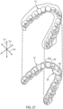
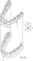
- biasing member 62 and related structures disclosed in Figures 32-36 and the corresponding written description may be applied to an appliance 10 have features 22 disclosed in Figures 37-51 and the corresponding written description.
- an appliance 10 in accordance with the present invention may include a tongue-retention feature 98.
- an upper portion 12 of an appliance 10 may include, be connected to, or support a tongue-retention feature 98.
- a tongue-retention feature 98 may engage a tongue 100 of a patient so as to hold the tongue 100 in a forward position within the mouth of the patient. Accordingly, during sleep, a tongue-retention feature 98 may prevent a tongue 100 from falling back within the mouth of a patient and inhibiting breathing.
- a tongue-retention feature 98 may enable an appliance 10 to better combat sleep apnea.
- a tongue-retention feature 98 may be a cavity into which a patient may insert his or her tongue 100. As a tongue 100 is inserted within a cavity defined by a tongue-retention feature 98, the air therewithin may be expelled. Accordingly, when a tongue 100 is fully seated within a tongue-retention feature 98, the moist exterior of the tongue 100 may interact with an interior surface 102 of the tongue-retention feature 98 to create a suction effect resisting extraction of the tongue 100 from the tongue-retention feature 98.
- a tongue-retention feature 98 may hold a tongue 100 in a forward position until the suction effect is broken (e.g., broken by flexing, moving, or distorting a tongue 100 in a manner that permits air to pass between the tongue 100 and the tongue-retention feature 98).
- a tongue-retention feature 98 may be shaped to create and preserve a desired suction effect.
- a tongue-retention feature 98 may have a somewhat conical shape. That is, a tongue-retention feature 98 may have an interior surface 102 that tapers out from a relatively narrow anterior tip 104 to a relatively wide posterior opening 106.
- a tongue-retention feature 98 may have a shape that resembles the forward portion of a tongue 100 of a patient. Accordingly, a tip 108 of a tongue 100 may comfortably fit within and fill an anterior tip 104, while a more-posterior portion of a tongue 100 may fit within (e.g., mostly or substantially fill) a posterior opening 106.
- An interior surface 102 of a tongue-retention feature 98 may be shaped and configured to create and preserve a desired suction effect.
- an interior surface 102 may be smooth and rounded without discontinuities or other irregularities that may permit an unwanted ingress of air between the interior surface 102 and the exterior of a tongue 100 (e.g., an unwanted ingress that may break a suction effect).
- An interior surface 102 may also have a finish selected to provide a desired amount of suction (e.g., a higher gloss finish when or where more suction is needed or a lower gloss or rougher finish when or where less suction is needed).
- a tongue-retention feature 98 is formed by or between an upper (i.e., palatal) member 110 and a lower (i.e., sublingual) member 112.
- An upper member 110 may extend within and/or bridge across an upper dental arch.
- An upper member 110 may be sized, shaped, and positioned to contact a forward, upper surface of a tongue 100.
- an upper member 110 may track (e.g., be formed to closely follow or match) at least a portion of the hard palate 114 of a patient. Accordingly, an upper member 110 may minimally impinge on the space (i.e., the space within a mouth) occupied by a tongue 100. This may improve the comfort with which an appliance 10 comprising a tongue-retention feature 98 may be worn.
- a lower member 112 may extend within and/or bridge across a lower dental arch.
- a lower member 112 may be sized, shaped, and positioned to contact a forward, lower surface of a tongue 100. Accordingly, a lower member 112 may extend proximate (e.g., proximate without impinging upon) an interior surface of an anterior region of the mandible of a patient.
- an upper member 110 may meet with, join, or blend into a lower member 112 at or near a corresponding base 20 (e.g., a base 20 corresponding to maxillary teeth 14).
- a lower portion 16 (rather than an upper portion 12) of an appliance 10 may include, be connected to, or support a tongue-retention feature 98.
- a tongue-retention feature 98 may move with a mandible of a patient.
- a dental appliance 10 may comprise a base 20 shaped to extend along at least a portion of an upper dental arch of a patient. Accordingly, a base 20 may have an arcuate shape or be referred to as an arcuate base 20.
- a base 20 may be shaped to match with a custom fit at least certain maxillary teeth 14 of the patient. That is, a base 20 may have a cavity 116 formed therein that tracks (e.g., closely follows selected contours of) at least selected maxillary teeth 14 of a patient. This may enable a base 20 to hold itself in place by selectively engaging one or more maxillary teeth 14 of a patient. In certain embodiments, a base 20 may be shaped to match with a custom fit all maxillary teeth 14 of the patient.
- a tongue-retention feature 98 may connect to a base 20.
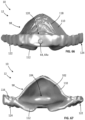
- a tongue-retention feature 98 may comprise a palatal portion or member 110 and a sublingual portion or member 112.
- a sublingual portion 112 may cooperate with a palatal portion 110 to form a cavity shaped to receive an anterior portion of a tongue 100 of the patient therewithin.
- a palatal portion 110 may have an exterior surface 118 custom formed to match at least a portion of a hard palate of the patient. Accordingly, an interior surface 102 of a palatal portion 110 may be smoother (e.g., have a smoother surface finish) than an exterior surface 118 of the palatal portion 110.
- a base 20 and tongue-retention feature 98 may form a complete dental appliance 10. That is, acting alone, a base 20 and tongue-retention feature 98 may provide all of the functionality of a dental appliance 10. Alternatively, a base 20 and tongue-retention feature 98 may form an upper portion 12 of a dental appliance 10. In such embodiments, a lower portion 16 may also form part of the dental appliance 10.
- a first feature 22a may be positioned on an anterior area of a base 20.
- a first feature 22a may be positioned opposite a second feature 22b of a lower portion 16.
- mandibular motion of a patient e.g., biting down
- an engagement mechanism 64 may connect to a base 20.
- mandibular motion or position of a patient may be influenced by one or more biasing members 62 extending from a lower portion 16 as explained hereinabove.
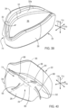
- a dental appliance 10 or an upper portion 12 of a dental appliance 10 may be a seamless unit formed in an additive manufacturing process.
- a base may comprise an anterior portion 120, a right portion 122 extending distally away from the anterior portion 120, and a left portion 124 extending distally away from the anterior portion 120.
- a palatal portion 110 may seamlessly extend from a lingual side of the right portion 122 to a lingual side of the left portion 124.
- a palatal portion 110 may further seamlessly extend from a lingual side of the anterior portion 120.
- a sublingual portion 112 may seamlessly extend from a lingual side of the right portion 122 and seamlessly extend from a lingual side of the left portion 124. A sublingual portion 112 may further seamlessly extend from a lingual side of the anterior portion 120.
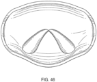
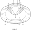
- a sublingual portion 112 may comprise a central notch 126 extending forward from a posterior extreme 128 of the sublingual portion 112 to provide clearance for a lingual frenulum of the patient.
- a posterior extreme 128 of a sublingual portion 112 may be rounded or curve or curl downward to enable a tongue 100 of a patient to more comfortably extend over the posterior extreme 128 and onto the sublingual portion 112.
- a tongue-retention feature 98 may be formed or defined by a sublingual portion 112 extending under an anterior portion of a tongue 100.
- a sublingual portion 112 may cooperate with a hard palate 114 of a patient to form a cavity for receiving and suctionally engaging an anterior portion of the tongue 100.
- a palatal portion 110 may be omitted.
- a first feature 22a and an engagement mechanism 64 are also omitted.
- a lifting of a tongue 100 may be the desired result for a tongue-retention feature 98.
- a tongue 100 e.g., hold an anterior portion of a tongue up against the hard palate 114
- a sublingual portion 112 may be perforated by one or more apertures 130. The number of, size of, and spacing between such apertures 130 may be selected to provide a desired reduction in a suction effect and/or a desired moistening of an underside of the tongue 100.
- an appliance 10 having a tongue-retention feature 98 in accordance with the present invention may be manufactured in any suitable manner.
- a method 132 of manufacture may use three dimensional printing (i.e., an additive manufacturing process) to produce a base 20, anterior feature 22, engagement mechanism 64, tongue-retention feature 98, or the like or a combination or sub-combination thereof as a monolithic (i.e., seamless) unit.
- a three dimensional image of a patient's mouth may be obtained 134 via a digital scan.
- the three dimensional image may be a digital model of at least certain maxillary teeth 14 of a patient and at least a portion of a hard palate 114 of the patient.
- Such an image or model may be used 136 to create a virtual dental appliance 10 within a computer system.
- a three dimensional image or model may be imported into a computer-aided drafting (CAD) application, a computer-aided drafting and manufacturing (CAD/CAM) application, or the like where it may be used 136 as a basis or template for creating a virtual base 20 or a combination of a virtual base 20 and a virtual palatal portion 110.
- CAD computer-aided drafting
- CAD/CAM computer-aided drafting and manufacturing
- a virtual dental appliance 10 or some independent part thereof e.g., a virtual upper portion 12 of a dental appliance 10) is properly created 136, it may be printed in a polymeric material using a three dimensional printing process. That is, an additive manufacturing process may be employed 138 to convert a virtual dental appliance 10 into an actual dental appliance 10 custom made for the patient.
- using 136 a digital model to create a virtual dental appliance 10 within a computer system may involve multiple steps or processes.
- such using 136 may include one or more of: (1) virtually forming 140 within a computer system a base 20 (e.g., an arcuate base 20) shaped to extend along at least a portion of an upper dental arch of a patient and match with a custom fit at least certain maxillary teeth 14; (2) virtually forming 142 a palatal portion 110 connected to the base 20 and having an exterior surface 118 custom-formed to match at least a portion of the hard palate 114 of the patient; (3) selecting 144 a virtual standardized sublingual portion 112 stored within the computer system; (4) virtually positioning 146 the standardized sublingual portion 112 with respect to the base 20; and (5) virtually connecting 148 the standardized sublingual portion 112 to the base 20.
- the step or process of virtually forming 142 a palatal portion 110 may be omitted when that component is not to be included within the dental appliance 10.
- virtually connecting 148 a standardized sublingual portion 112 to a base 20 may include filling and/or smoothing one or more interfaces and/or junctions therebetween so as to provide the desired comfort, strength, and functionality in the actual appliance 10.
- a digital model to create a virtual dental appliance 10 within a computer system may involve using a CAD application, CAD/CAM application, or the like.
- such using 136 may further include employing a CAD or CAD/CAM application to import an anterior feature 22 (e.g., a first feature 22a) into the three dimensional model (e.g., into a virtual dental appliance 10).
- the anterior feature 22 may be a predefined, standard part. Accordingly, it may be imported and located as desired.
- a CAD or CAD/CAM application may be further used to import an engagement mechanism 64 into the three dimensional model.
- the engagement mechanism 64 may also be a predefined, standard part. Accordingly, it may be imported and located as desired.
- a CAD application, a CAD/CAM application, or the like to create may be used to a custom sublingual portion 112. Accordingly, a sublingual portion 112 may be created for each patient with such an application. In such embodiments, creating, sizing, shaping, and/or positioning a sublingual portion 112 may replace certain steps 144, 146, 148 of the method 136 disclosed above.
- a tool 150 may assist in determining how to virtually position 146 a standardized sublingual portion with respect to a base 20.
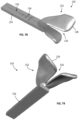
- a tool 150 may be an actual version of a standardized sublingual portion 112.
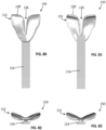
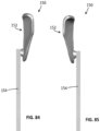
- both a tool 150 and a standardized sublingual portion 112 may include a sublingual template 152, and a handle 154 connected to the sublingual template 152.
- a sublingual template 152 may include a notch 126, rounded or curled posterior edge 128, and the like just like a finished sublingual portion 112.
- a handle 154 may be an elongated member extending forward away from a front end of a corresponding sublingual template 152.
- a handle 154 may include one or more structures 156 (e.g., markings or indentations) formed therein or thereon.
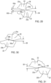
- a method 158 for using a tool 150 may include one or more of: (1) obtaining a tool 150 matching a standardized sublingual portion 112; (2) inserting the sublingual template 152 portion of the tool 150 into the mouth of a patient; (3) positioning the sublingual template 152 below an anterior portion of the tongue 100 of the patient; (4) manipulating the handle 154 of the tool to lift the tongue 100 of the patient into a desired position against the hard palate 114 of the patient; and (5) capturing one or more reference images (e.g., a reference digital model) of a relative position of the handle 154 with respect to selected maxillary teeth 14 (e.g., central incisors) of the patient when the sublingual template 152 is positioned to hold the tongue in the desired position.
- reference images e.g., a reference digital model
- positioning 146 a standardized sublingual portion 112 may become: (1) virtually positioning the virtual standardized sublingual portion 112 so that the handle 154 thereof is positioned with respect to virtual maxillary teeth 14 of the patient the same as the handle 154 and teeth 14 in the one or more reference images or the reference digital model; and (2) virtually deleting the handle 154.
- one or more structures 156 on a handle 154 may provide visual markers that aid (e.g., aid a human or computer) in virtually positioning the virtual standardized sublingual portion 112 so that the handle 154 thereof is positioned with respect to virtual maxillary teeth 14 of the patient the same as the handle 154 and teeth 14 in the one or more reference images or the reference digital model.
- a tool 150 may enable a dental professional or the like to position a sublingual template 152 in a position that works for a patient (e.g., is comfortable for the patient and positions the tongue 100 of the patient in a desired position) and then reliably replicate that position in a virtual space.
Landscapes
- Engineering & Computer Science (AREA)
- Health & Medical Sciences (AREA)
- Materials Engineering (AREA)
- Chemical & Material Sciences (AREA)
- Manufacturing & Machinery (AREA)
- Public Health (AREA)
- Medical Informatics (AREA)
- General Health & Medical Sciences (AREA)
- Biomedical Technology (AREA)
- Epidemiology (AREA)
- Pulmonology (AREA)
- Data Mining & Analysis (AREA)
- Pathology (AREA)
- Optics & Photonics (AREA)
- Mechanical Engineering (AREA)
- Physics & Mathematics (AREA)
- Primary Health Care (AREA)
- Otolaryngology (AREA)
- Databases & Information Systems (AREA)
- Nursing (AREA)
- Orthopedic Medicine & Surgery (AREA)
- Heart & Thoracic Surgery (AREA)
- Vascular Medicine (AREA)
- Life Sciences & Earth Sciences (AREA)
- Animal Behavior & Ethology (AREA)
- Veterinary Medicine (AREA)
- Dental Tools And Instruments Or Auxiliary Dental Instruments (AREA)
- Orthopedics, Nursing, And Contraception (AREA)
Claims (15)
- Verfahren umfassend:Erhalten (134) eines digitalen Modells von mindestens bestimmten Oberkieferzähnen eines Patienten und von wenigstens einem Teil eines harten Gaumens des Patienten; undVerwenden (136) des digitalen Modells, um eine virtuelle zahnärztliche Vorrichtung (10) in einem Computersystem zu schaffen, wobei das Verwenden umfasst:Virtuelles Ausbilden (140) einer bogenförmigen Basis (20), die so geformt ist, dass sie sich entlang wenigstens eines Abschnitts eines oberen Zahnbogens eines Patienten erstreckt und mit einer individuellen Passform zu den mindestens bestimmten Oberkieferzähnen passt,Virtuelles Ausbilden (142) eines Gaumenbereichs (110), der mit der bogenförmigen Basis (20) verbunden ist,gekennzeichnet dadurch,dass der Gaumenbereich (110) eine äußere Oberfläche (118) hat, die passgenau geformt ist, um zu wenigstens dem einen Teil des harten Gaumens zu passen,wobei das Verfahren weiter umfasstAuswählen (144) eines standardisierten sublingualen Abschnitts (112), der in dem Computersystem gespeichert ist,virtuelles Positionieren (146) des standardisierten sublingualen Abschnitts (112) in Bezug auf den Gaumenbereich (110), so dass der standardisierte sublinguale Abschnitt (112) mit dem Gaumenbereich (110) zusammenwirkt, um einen Hohlraum zu schaffen, der so geformt ist, dass er einen vorderen Teil einer Zunge des Patienten darin aufnimmt, undvirtuelles Verbinden (148) des standardisierten sublingualen Abschnitts (112) mit wenigstens einem von der bogenförmigen Basis (20) und dem Gaumenbereich (110).
- Verfahren nach Patentanspruch 1, weiterhin umfassend Anwenden (138) eines additiven Fertigungsprozesses, um die virtuelle zahnärztliche Vorrichtung (10) in eine tatsächliche zahnärztliche Vorrichtung (10) umzuwandeln, die passgenau hergestellt ist für den Patienten.
- Verfahren nach Patentanspruch 1 oder 2, wobei das virtuelle Verbinden (146) des standardisierten sublingualen Abschnitts (112) weiter virtuelles Glätten eines Übergangs zwischen dem standardisierten sublingualen Abschnitt (112) und dem wenigstens einen von der bogenförmigen Basis (20) und dem Gaumenbereich (110) umfasst.
- Verfahren nach Patentanspruch 1, 2, oder 3, wobei:das virtuelle Ausbilden der bogenförmigen Basis (20) virtuelles Ausbilden der bogenförmigen Basis (20) umfasst, um einen vorderen Abschnitt, einen rechten Abschnitt, der sich distal weg von dem vorderen Abschnitt erstreckt, und einen linken Abschnitt, der sich distal weg von dem vorderen Abschnitt erstreckt, einzuschließen;wobei das virtuelle Ausbilden des Gaumenbereichs (110) virtuelles Ausbilden des Gaumenbereichs (110) umfasst, so dass er sich sich nahtlos von einer lingualen Seite des rechten Abschnitts zu einer lingualen Seite des linken Abschnitts erstreckt; undwobei das virtuelle Ausbilden des Gaumenbereichs (110) Ausbilden des Gaumenbereichs (110) umfasst, so dass er sich nahtlos ausgehend von einer lingualen Seite des vorderen Abschnitts erstreckt.
- Verfahren nach Patentanspruch 4, wobei:das virtuelle Positionieren des sublingualen Abschnitts (112) virtuelles Positionieren des sublingualen Abschnitts (112) umfasst, um sich nahtlos ausgehend von einer lingualen Seite des rechten Abschnitts zu erstrecken und um sich nahtlos ausgehend von einer lingualen Seite des linken Abschnitts zu erstrecken;das virtuelle Positionieren des sublingualen Abschnitts (112) virtuelles Positionieren des sublingualen Abschnitts (112) umfasst, um sich nahtlos ausgehend von einer lingualen Seite des vorderen Abschnitts zu erstrecken; unddas virtuelle Positionieren des sublingualen Abschnitts (112) virtuelles Positionieren des sublingualen Abschnitts umfasst, um eine zentrale Aussparung (126) einzuschließen, welche sich von einem hinteren Ende des sublingualen Abschnitts (112) nach vorne erstreckt, um einen Freiraum für ein Zungenbändchen des Patienten bereitzustellen.
- Dentale Vorrichtung (10), umfassend:eine bogenförmige Basis (20), die so geformt ist, dass sie sich entlang wenigstens eines Abschnitts eines oberen Zahnbogens eines Patienten erstreckt und mit einer individuellen Passform zu mindestens bestimmten Oberkieferzähnen des Patienten passt;
undeine Zungenrückhalteeinrichtung (98), die mit der bogenförmigen Basis (20) verbunden ist und die einen Gaumenbereich (110) und einen sublingualen Abschnitt (112) umfasst, wobei der sublinguale Abschnitt (112) mit dem Gaumenbereich (110) zusammenwirkt, um einen Hohlraum zu schaffen, der so geformt ist, dass er einen vorderen Teil einer Zunge des Patienten darin aufnimmt,dadurch gekennzeichnet, dass der Gaumenbereich (110) eine äußere Oberfläche (118) hat, die individuell so geformt ist, dass sie wenigstens zu einem Teil eines harten Gaumens des Patienten passt. - Dentale Vorrichtung nach Patentanspruch 6, wobei die dentale Vorrichtung (10) eine nahtlose Einheit ist.
- Dentale Vorrichtung nach Patentanspruch 6 oder 7, worin die bogenförmige Basis (20) zu allen Oberkieferzähnen des Patienten passgenau passt.
- Dentale Vorrichtung nach Patentanspruch 6, 7, oder 8, worin die bogenförmige Basis (20) einen vorderen Abschnitt, einen rechten Abschnitt, der sich distal weg von dem vorderen Abschnitt erstreckt, und einen linken Abschnitt, der sich distal weg von dem vorderen Abschnitt erstreckt, umfasst.
- Dentale Vorrichtung nach Patentanspruch 9, worin der Gaumenbereich (110) sich nahtlos von einer lingualen Seite des rechten Abschnitts zu einer lingualen Seite des linken Abschnitts erstreckt.
- Dentale Vorrichtung nach Patentanspruch 10, worin der Gaumenbereich (110) sich nahtlos von einer lingualen Seite des vorderen Abschnitts erstreckt.
- Dentale Vorrichtung nach Patentanspruch 9, 10, oder 11, worin der sublinguale Abschnitt (112) sich nahtlos von einer lingualen Seite des rechten Abschnitts erstreckt und sich nahtlos von einer lingualen Seite des linken Abschnitts erstreckt.
- Dentale Vorrichtung nach Patentanspruch 12, worin der sublinguale Abschnitt (112) sich nahtlos von einer lingualen Seite des vorderen Abschnitts erstreckt.
- Dentale Vorrichtung nach Patentanspruch 6, 7, 8, 9, 10, 11, 12, oder 13, worin der sublinguale Abschnitt (112) eine zentrale Aussparung (126) umfasst, welche sich von einem hinteren Ende des sublingualen Abschnitts (112) nach vorne erstreckt, um einen Freiraum für ein Zungenbändchen des Patienten bereitzustellen.
- Dentale Vorrichtung nach Patentanspruch 6, 7, 8, 9, 10, 11, 12, 13, oder 14, worin eine Innenfläche (102) des Gaumenbereichs (110) glatter ist als eine äußere Oberfläche (118) des Gaumenbereichs (110).
Applications Claiming Priority (2)
| Application Number | Priority Date | Filing Date | Title |
|---|---|---|---|
| US201962855792P | 2019-05-31 | 2019-05-31 | |
| PCT/US2020/035606 WO2020243723A1 (en) | 2019-05-31 | 2020-06-01 | Dental appliance for treatment of bruxism and sleep apnea |
Publications (3)
| Publication Number | Publication Date |
|---|---|
| EP3976352A1 EP3976352A1 (de) | 2022-04-06 |
| EP3976352A4 EP3976352A4 (de) | 2023-02-01 |
| EP3976352B1 true EP3976352B1 (de) | 2024-08-28 |
Family
ID=73551160
Family Applications (1)
| Application Number | Title | Priority Date | Filing Date |
|---|---|---|---|
| EP20814236.4A Active EP3976352B1 (de) | 2019-05-31 | 2020-06-01 | Zahnärztliches gerät zur behandlung von bruxismus und schlafapnoe |
Country Status (4)
| Country | Link |
|---|---|
| US (1) | US12502305B2 (de) |
| EP (1) | EP3976352B1 (de) |
| CN (1) | CN114206592A (de) |
| WO (1) | WO2020243723A1 (de) |
Families Citing this family (3)
| Publication number | Priority date | Publication date | Assignee | Title |
|---|---|---|---|---|
| US20240238112A1 (en) * | 2023-01-16 | 2024-07-18 | TMJ Services, LLC | Integrally formed device for mitigation of temporomandibular joint disorder |
| WO2025233883A1 (en) * | 2024-05-08 | 2025-11-13 | Institut Straumann Ag | Mandibular advancement system and method of use |
| KR102947988B1 (ko) * | 2024-10-08 | 2026-04-03 | 주식회사 더슬립팩토리 | 수면 장애 개선을 위한 맞춤형 구강 장치의 3d 모델링을 통한 제조 방법, 장치, 시스템 및 컴퓨터 프로그램 |
Family Cites Families (27)
| Publication number | Priority date | Publication date | Assignee | Title |
|---|---|---|---|---|
| US4304227A (en) * | 1978-03-03 | 1981-12-08 | Samelson Charles F | Device for treatment of snoring, bruxism or for avoidance of sleep apnea |
| US4997182A (en) * | 1989-10-12 | 1991-03-05 | Leon Kussick | Tongue thrust corrective device |
| CA2088935A1 (en) | 1992-11-16 | 1994-05-17 | Thomas E. Meade | Apparatus and methods for reduction of snoring |
| US5649540A (en) | 1994-01-12 | 1997-07-22 | Snorex, Inc. | Tongue positioning device for medical procedures |
| US6877513B2 (en) | 2000-01-21 | 2005-04-12 | Respironics, Inc. | Intraoral apparatus for enhancing airway patency |
| US6494209B2 (en) | 2001-04-02 | 2002-12-17 | George Kulick | Method and apparatus for treatment of snoring, hypopnea and apnea |
| US6837246B1 (en) * | 2001-09-14 | 2005-01-04 | Deluke Anthony G. | Tongue-airway appliance |
| US20030116164A1 (en) | 2001-12-14 | 2003-06-26 | Boyd James P. | Intraoral discluder device and method for preventing migraine, tension headache, and temporomandibular disorders |
| WO2006125216A2 (en) | 2005-05-19 | 2006-11-23 | Summer John D | Tongue grasping and restraining apparatus and methods |
| US20070183572A1 (en) * | 2006-01-13 | 2007-08-09 | Arielle Drummond | Apparatus and method for manufacturing a mandibular advancement device |
| US8347890B2 (en) | 2006-06-19 | 2013-01-08 | Insono Therapeutics, Inc. | Automated tissue retention system |
| US7607439B2 (en) | 2006-06-19 | 2009-10-27 | Li Kasey K | Tongue retention system |
| US8857439B2 (en) | 2006-06-19 | 2014-10-14 | Insono Therapeutics, Inc. | Variable automated tissue retention system |
| US8122889B2 (en) | 2007-11-13 | 2012-02-28 | Apnicure, Inc. | Methods and systems for improving airway patency |
| FR2934769B1 (fr) | 2008-08-06 | 2010-09-17 | Claude Mauclaire | Appareil dentaire de contrainte de la langue pour corriger la macroglossie et l'apnee du sommeil. |
| US8196587B2 (en) | 2008-12-16 | 2012-06-12 | Ranir Llc | Bruxism protective device |
| US8261748B1 (en) | 2010-09-15 | 2012-09-11 | Howell Goldberg | Oral device for treating sleep apnea |
| EP2730258B1 (de) * | 2012-11-09 | 2016-05-11 | Orthotixx Dental AG | Aufbissschiene |
| US20180200102A1 (en) | 2013-07-01 | 2018-07-19 | R. Joseph Magness | Dental appliance for treatment of bruxism and sleep apnea |
| US12213906B2 (en) * | 2013-07-01 | 2025-02-04 | R. Joseph Magness | Dental appliance for treatment of sleep apnea |
| US10080680B2 (en) | 2013-07-01 | 2018-09-25 | R. Joseph Magness | Dental appliance for treatment of bruxism |
| US9956111B2 (en) | 2013-10-24 | 2018-05-01 | Dante Togliatti | Dental appliance |
| EP3331476A4 (de) | 2015-08-03 | 2020-03-11 | Oventus Medical Limited | Atmungsunterstützungsvorrichtung |
| EP3507730B1 (de) * | 2016-08-31 | 2021-05-19 | Lucas, Kelly | System und verfahren zur herstellung von zahnlösungen mit einem anleitungspaket |
| CN111050693B (zh) | 2017-08-16 | 2022-02-18 | 盖百加有限公司 | 制造牙套的系统和方法 |
| WO2019060624A2 (en) | 2017-09-22 | 2019-03-28 | Shah Mamta Ketan | SYSTEMS, METHODS AND DEVICES FOR TREATING DISORDERS OF THE MOUTH AND JAW |
| DE102017217558A1 (de) * | 2017-10-02 | 2019-04-04 | Sirona Dental Systems Gmbh | Verfahren zur Herstellung einer geführten Aufbissschiene und eine geführte Aufbissschiene |
-
2020
- 2020-06-01 EP EP20814236.4A patent/EP3976352B1/de active Active
- 2020-06-01 CN CN202080054260.0A patent/CN114206592A/zh active Pending
- 2020-06-01 WO PCT/US2020/035606 patent/WO2020243723A1/en not_active Ceased
- 2020-06-01 US US16/889,662 patent/US12502305B2/en active Active
Also Published As
| Publication number | Publication date |
|---|---|
| EP3976352A4 (de) | 2023-02-01 |
| EP3976352A1 (de) | 2022-04-06 |
| US12502305B2 (en) | 2025-12-23 |
| US20200375790A1 (en) | 2020-12-03 |
| CN114206592A (zh) | 2022-03-18 |
| WO2020243723A1 (en) | 2020-12-03 |
Similar Documents
| Publication | Publication Date | Title |
|---|---|---|
| EP3016621B1 (de) | Zahnärztliche vorrichtung zum behandeln von zähneknirschen | |
| US11504213B2 (en) | Anterior guidance package, kit, and constructing method thereof | |
| US7861721B2 (en) | Appliance, system and method for preventing snoring | |
| US20250228700A1 (en) | Dental Appliance for Treatment of Sleep Apnea | |
| US8201560B2 (en) | Flexible dental appliance | |
| US7918228B2 (en) | Musculoskeletal repositioning device | |
| US20180042759A1 (en) | Pre-programmed anterior guidance package, kit, and method | |
| US6837246B1 (en) | Tongue-airway appliance | |
| US20070292819A1 (en) | Oral appliance for treatment of snoring and sleep apnea | |
| US8585401B2 (en) | Mouthpiece for athletic performance enhancement | |
| US12502305B2 (en) | Dental appliance for treatment of bruxism and sleep apnea | |
| IL264564B2 (en) | A system and method for producing a dental solution that includes a training package | |
| KR20190069653A (ko) | 구강 장치 및 그 제조 방법 | |
| US10799322B2 (en) | Oral anterior guidance packages, systems, and components | |
| US11285035B2 (en) | Single arch dental device and method of manufacture | |
| US20180200102A1 (en) | Dental appliance for treatment of bruxism and sleep apnea | |
| US20210015658A1 (en) | Oral appliances, packages, systems, and components | |
| CN106806028A (zh) | Ry-双颌诱导器 |
Legal Events
| Date | Code | Title | Description |
|---|---|---|---|
| STAA | Information on the status of an ep patent application or granted ep patent |
Free format text: STATUS: THE INTERNATIONAL PUBLICATION HAS BEEN MADE |
|
| PUAI | Public reference made under article 153(3) epc to a published international application that has entered the european phase |
Free format text: ORIGINAL CODE: 0009012 |
|
| STAA | Information on the status of an ep patent application or granted ep patent |
Free format text: STATUS: REQUEST FOR EXAMINATION WAS MADE |
|
| 17P | Request for examination filed |
Effective date: 20211222 |
|
| AK | Designated contracting states |
Kind code of ref document: A1 Designated state(s): AL AT BE BG CH CY CZ DE DK EE ES FI FR GB GR HR HU IE IS IT LI LT LU LV MC MK MT NL NO PL PT RO RS SE SI SK SM TR |
|
| DAV | Request for validation of the european patent (deleted) | ||
| DAX | Request for extension of the european patent (deleted) | ||
| A4 | Supplementary search report drawn up and despatched |
Effective date: 20230105 |
|
| RIC1 | Information provided on ipc code assigned before grant |
Ipc: B33Y 50/00 20150101ALI20221223BHEP Ipc: B33Y 80/00 20150101ALI20221223BHEP Ipc: G16H 50/50 20180101ALI20221223BHEP Ipc: A61F 5/56 20060101ALI20221223BHEP Ipc: B29C 64/386 20170101AFI20221223BHEP |
|
| RAP3 | Party data changed (applicant data changed or rights of an application transferred) |
Owner name: MAGNESS, R. JOSEPH |
|
| RIN1 | Information on inventor provided before grant (corrected) |
Inventor name: MAGNESS, R. JOSEPH |
|
| GRAP | Despatch of communication of intention to grant a patent |
Free format text: ORIGINAL CODE: EPIDOSNIGR1 |
|
| STAA | Information on the status of an ep patent application or granted ep patent |
Free format text: STATUS: GRANT OF PATENT IS INTENDED |
|
| RIC1 | Information provided on ipc code assigned before grant |
Ipc: B33Y 50/00 20150101ALI20231017BHEP Ipc: B33Y 80/00 20150101ALI20231017BHEP Ipc: G16H 50/50 20180101ALI20231017BHEP Ipc: A61F 5/56 20060101ALI20231017BHEP Ipc: B29C 64/386 20170101AFI20231017BHEP |
|
| INTG | Intention to grant announced |
Effective date: 20231114 |
|
| GRAJ | Information related to disapproval of communication of intention to grant by the applicant or resumption of examination proceedings by the epo deleted |
Free format text: ORIGINAL CODE: EPIDOSDIGR1 |
|
| STAA | Information on the status of an ep patent application or granted ep patent |
Free format text: STATUS: REQUEST FOR EXAMINATION WAS MADE |
|
| GRAP | Despatch of communication of intention to grant a patent |
Free format text: ORIGINAL CODE: EPIDOSNIGR1 |
|
| STAA | Information on the status of an ep patent application or granted ep patent |
Free format text: STATUS: GRANT OF PATENT IS INTENDED |
|
| INTC | Intention to grant announced (deleted) | ||
| INTG | Intention to grant announced |
Effective date: 20240328 |
|
| GRAS | Grant fee paid |
Free format text: ORIGINAL CODE: EPIDOSNIGR3 |
|
| GRAA | (expected) grant |
Free format text: ORIGINAL CODE: 0009210 |
|
| STAA | Information on the status of an ep patent application or granted ep patent |
Free format text: STATUS: THE PATENT HAS BEEN GRANTED |
|
| AK | Designated contracting states |
Kind code of ref document: B1 Designated state(s): AL AT BE BG CH CY CZ DE DK EE ES FI FR GB GR HR HU IE IS IT LI LT LU LV MC MK MT NL NO PL PT RO RS SE SI SK SM TR |
|
| REG | Reference to a national code |
Ref country code: CH Ref legal event code: EP |
|
| REG | Reference to a national code |
Ref country code: DE Ref legal event code: R096 Ref document number: 602020036781 Country of ref document: DE |
|
| REG | Reference to a national code |
Ref country code: IE Ref legal event code: FG4D |
|
| REG | Reference to a national code |
Ref country code: LT Ref legal event code: MG9D |
|
| PG25 | Lapsed in a contracting state [announced via postgrant information from national office to epo] |
Ref country code: NO Free format text: LAPSE BECAUSE OF FAILURE TO SUBMIT A TRANSLATION OF THE DESCRIPTION OR TO PAY THE FEE WITHIN THE PRESCRIBED TIME-LIMIT Effective date: 20241128 |
|
| REG | Reference to a national code |
Ref country code: AT Ref legal event code: MK05 Ref document number: 1717511 Country of ref document: AT Kind code of ref document: T Effective date: 20240828 |
|
| PG25 | Lapsed in a contracting state [announced via postgrant information from national office to epo] |
Ref country code: NL Free format text: LAPSE BECAUSE OF FAILURE TO SUBMIT A TRANSLATION OF THE DESCRIPTION OR TO PAY THE FEE WITHIN THE PRESCRIBED TIME-LIMIT Effective date: 20240828 Ref country code: PL Free format text: LAPSE BECAUSE OF FAILURE TO SUBMIT A TRANSLATION OF THE DESCRIPTION OR TO PAY THE FEE WITHIN THE PRESCRIBED TIME-LIMIT Effective date: 20240828 Ref country code: GR Free format text: LAPSE BECAUSE OF FAILURE TO SUBMIT A TRANSLATION OF THE DESCRIPTION OR TO PAY THE FEE WITHIN THE PRESCRIBED TIME-LIMIT Effective date: 20241129 Ref country code: PT Free format text: LAPSE BECAUSE OF FAILURE TO SUBMIT A TRANSLATION OF THE DESCRIPTION OR TO PAY THE FEE WITHIN THE PRESCRIBED TIME-LIMIT Effective date: 20241230 Ref country code: FI Free format text: LAPSE BECAUSE OF FAILURE TO SUBMIT A TRANSLATION OF THE DESCRIPTION OR TO PAY THE FEE WITHIN THE PRESCRIBED TIME-LIMIT Effective date: 20240828 |
|
| PG25 | Lapsed in a contracting state [announced via postgrant information from national office to epo] |
Ref country code: BG Free format text: LAPSE BECAUSE OF FAILURE TO SUBMIT A TRANSLATION OF THE DESCRIPTION OR TO PAY THE FEE WITHIN THE PRESCRIBED TIME-LIMIT Effective date: 20240828 |
|
| PG25 | Lapsed in a contracting state [announced via postgrant information from national office to epo] |
Ref country code: LV Free format text: LAPSE BECAUSE OF FAILURE TO SUBMIT A TRANSLATION OF THE DESCRIPTION OR TO PAY THE FEE WITHIN THE PRESCRIBED TIME-LIMIT Effective date: 20240828 |
|
| REG | Reference to a national code |
Ref country code: NL Ref legal event code: MP Effective date: 20240828 |
|
| PG25 | Lapsed in a contracting state [announced via postgrant information from national office to epo] |
Ref country code: AT Free format text: LAPSE BECAUSE OF FAILURE TO SUBMIT A TRANSLATION OF THE DESCRIPTION OR TO PAY THE FEE WITHIN THE PRESCRIBED TIME-LIMIT Effective date: 20240828 Ref country code: IS Free format text: LAPSE BECAUSE OF FAILURE TO SUBMIT A TRANSLATION OF THE DESCRIPTION OR TO PAY THE FEE WITHIN THE PRESCRIBED TIME-LIMIT Effective date: 20241228 |
|
| PG25 | Lapsed in a contracting state [announced via postgrant information from national office to epo] |
Ref country code: HR Free format text: LAPSE BECAUSE OF FAILURE TO SUBMIT A TRANSLATION OF THE DESCRIPTION OR TO PAY THE FEE WITHIN THE PRESCRIBED TIME-LIMIT Effective date: 20240828 |
|
| PG25 | Lapsed in a contracting state [announced via postgrant information from national office to epo] |
Ref country code: RS Free format text: LAPSE BECAUSE OF FAILURE TO SUBMIT A TRANSLATION OF THE DESCRIPTION OR TO PAY THE FEE WITHIN THE PRESCRIBED TIME-LIMIT Effective date: 20241128 Ref country code: ES Free format text: LAPSE BECAUSE OF FAILURE TO SUBMIT A TRANSLATION OF THE DESCRIPTION OR TO PAY THE FEE WITHIN THE PRESCRIBED TIME-LIMIT Effective date: 20240828 |
|
| PG25 | Lapsed in a contracting state [announced via postgrant information from national office to epo] |
Ref country code: RS Free format text: LAPSE BECAUSE OF FAILURE TO SUBMIT A TRANSLATION OF THE DESCRIPTION OR TO PAY THE FEE WITHIN THE PRESCRIBED TIME-LIMIT Effective date: 20241128 Ref country code: PT Free format text: LAPSE BECAUSE OF FAILURE TO SUBMIT A TRANSLATION OF THE DESCRIPTION OR TO PAY THE FEE WITHIN THE PRESCRIBED TIME-LIMIT Effective date: 20241230 Ref country code: PL Free format text: LAPSE BECAUSE OF FAILURE TO SUBMIT A TRANSLATION OF THE DESCRIPTION OR TO PAY THE FEE WITHIN THE PRESCRIBED TIME-LIMIT Effective date: 20240828 Ref country code: NO Free format text: LAPSE BECAUSE OF FAILURE TO SUBMIT A TRANSLATION OF THE DESCRIPTION OR TO PAY THE FEE WITHIN THE PRESCRIBED TIME-LIMIT Effective date: 20241128 Ref country code: NL Free format text: LAPSE BECAUSE OF FAILURE TO SUBMIT A TRANSLATION OF THE DESCRIPTION OR TO PAY THE FEE WITHIN THE PRESCRIBED TIME-LIMIT Effective date: 20240828 Ref country code: LV Free format text: LAPSE BECAUSE OF FAILURE TO SUBMIT A TRANSLATION OF THE DESCRIPTION OR TO PAY THE FEE WITHIN THE PRESCRIBED TIME-LIMIT Effective date: 20240828 Ref country code: IS Free format text: LAPSE BECAUSE OF FAILURE TO SUBMIT A TRANSLATION OF THE DESCRIPTION OR TO PAY THE FEE WITHIN THE PRESCRIBED TIME-LIMIT Effective date: 20241228 Ref country code: HR Free format text: LAPSE BECAUSE OF FAILURE TO SUBMIT A TRANSLATION OF THE DESCRIPTION OR TO PAY THE FEE WITHIN THE PRESCRIBED TIME-LIMIT Effective date: 20240828 Ref country code: GR Free format text: LAPSE BECAUSE OF FAILURE TO SUBMIT A TRANSLATION OF THE DESCRIPTION OR TO PAY THE FEE WITHIN THE PRESCRIBED TIME-LIMIT Effective date: 20241129 Ref country code: FI Free format text: LAPSE BECAUSE OF FAILURE TO SUBMIT A TRANSLATION OF THE DESCRIPTION OR TO PAY THE FEE WITHIN THE PRESCRIBED TIME-LIMIT Effective date: 20240828 Ref country code: ES Free format text: LAPSE BECAUSE OF FAILURE TO SUBMIT A TRANSLATION OF THE DESCRIPTION OR TO PAY THE FEE WITHIN THE PRESCRIBED TIME-LIMIT Effective date: 20240828 Ref country code: BG Free format text: LAPSE BECAUSE OF FAILURE TO SUBMIT A TRANSLATION OF THE DESCRIPTION OR TO PAY THE FEE WITHIN THE PRESCRIBED TIME-LIMIT Effective date: 20240828 Ref country code: AT Free format text: LAPSE BECAUSE OF FAILURE TO SUBMIT A TRANSLATION OF THE DESCRIPTION OR TO PAY THE FEE WITHIN THE PRESCRIBED TIME-LIMIT Effective date: 20240828 |
|
| PG25 | Lapsed in a contracting state [announced via postgrant information from national office to epo] |
Ref country code: DK Free format text: LAPSE BECAUSE OF FAILURE TO SUBMIT A TRANSLATION OF THE DESCRIPTION OR TO PAY THE FEE WITHIN THE PRESCRIBED TIME-LIMIT Effective date: 20240828 Ref country code: RO Free format text: LAPSE BECAUSE OF FAILURE TO SUBMIT A TRANSLATION OF THE DESCRIPTION OR TO PAY THE FEE WITHIN THE PRESCRIBED TIME-LIMIT Effective date: 20240828 Ref country code: SM Free format text: LAPSE BECAUSE OF FAILURE TO SUBMIT A TRANSLATION OF THE DESCRIPTION OR TO PAY THE FEE WITHIN THE PRESCRIBED TIME-LIMIT Effective date: 20240828 |
|
| PG25 | Lapsed in a contracting state [announced via postgrant information from national office to epo] |
Ref country code: EE Free format text: LAPSE BECAUSE OF FAILURE TO SUBMIT A TRANSLATION OF THE DESCRIPTION OR TO PAY THE FEE WITHIN THE PRESCRIBED TIME-LIMIT Effective date: 20240828 |
|
| PG25 | Lapsed in a contracting state [announced via postgrant information from national office to epo] |
Ref country code: CZ Free format text: LAPSE BECAUSE OF FAILURE TO SUBMIT A TRANSLATION OF THE DESCRIPTION OR TO PAY THE FEE WITHIN THE PRESCRIBED TIME-LIMIT Effective date: 20240828 |
|
| PG25 | Lapsed in a contracting state [announced via postgrant information from national office to epo] |
Ref country code: SK Free format text: LAPSE BECAUSE OF FAILURE TO SUBMIT A TRANSLATION OF THE DESCRIPTION OR TO PAY THE FEE WITHIN THE PRESCRIBED TIME-LIMIT Effective date: 20240828 Ref country code: IT Free format text: LAPSE BECAUSE OF FAILURE TO SUBMIT A TRANSLATION OF THE DESCRIPTION OR TO PAY THE FEE WITHIN THE PRESCRIBED TIME-LIMIT Effective date: 20240828 |
|
| REG | Reference to a national code |
Ref country code: DE Ref legal event code: R097 Ref document number: 602020036781 Country of ref document: DE |
|
| PLBE | No opposition filed within time limit |
Free format text: ORIGINAL CODE: 0009261 |
|
| STAA | Information on the status of an ep patent application or granted ep patent |
Free format text: STATUS: NO OPPOSITION FILED WITHIN TIME LIMIT |
|
| PGFP | Annual fee paid to national office [announced via postgrant information from national office to epo] |
Ref country code: DE Payment date: 20250627 Year of fee payment: 6 |
|
| PGFP | Annual fee paid to national office [announced via postgrant information from national office to epo] |
Ref country code: GB Payment date: 20250627 Year of fee payment: 6 |
|
| PGFP | Annual fee paid to national office [announced via postgrant information from national office to epo] |
Ref country code: FR Payment date: 20250625 Year of fee payment: 6 |
|
| 26N | No opposition filed |
Effective date: 20250530 |
|
| PG25 | Lapsed in a contracting state [announced via postgrant information from national office to epo] |
Ref country code: SE Free format text: LAPSE BECAUSE OF FAILURE TO SUBMIT A TRANSLATION OF THE DESCRIPTION OR TO PAY THE FEE WITHIN THE PRESCRIBED TIME-LIMIT Effective date: 20240828 |
|
| REG | Reference to a national code |
Ref country code: CH Ref legal event code: H13 Free format text: ST27 STATUS EVENT CODE: U-0-0-H10-H13 (AS PROVIDED BY THE NATIONAL OFFICE) Effective date: 20260127 |
|
| PG25 | Lapsed in a contracting state [announced via postgrant information from national office to epo] |
Ref country code: MC Free format text: LAPSE BECAUSE OF FAILURE TO SUBMIT A TRANSLATION OF THE DESCRIPTION OR TO PAY THE FEE WITHIN THE PRESCRIBED TIME-LIMIT Effective date: 20240828 |
|
| PG25 | Lapsed in a contracting state [announced via postgrant information from national office to epo] |
Ref country code: LU Free format text: LAPSE BECAUSE OF NON-PAYMENT OF DUE FEES Effective date: 20250601 |
|
| REG | Reference to a national code |
Ref country code: BE Ref legal event code: MM Effective date: 20250630 |
|
| PG25 | Lapsed in a contracting state [announced via postgrant information from national office to epo] |
Ref country code: IE Free format text: LAPSE BECAUSE OF NON-PAYMENT OF DUE FEES Effective date: 20250601 |
|
| PG25 | Lapsed in a contracting state [announced via postgrant information from national office to epo] |
Ref country code: BE Free format text: LAPSE BECAUSE OF NON-PAYMENT OF DUE FEES Effective date: 20250630 |
|
| PG25 | Lapsed in a contracting state [announced via postgrant information from national office to epo] |
Ref country code: CH Free format text: LAPSE BECAUSE OF NON-PAYMENT OF DUE FEES Effective date: 20250630 |