EP3975784B1 - Sohlenstruktur für schuhwerk - Google Patents
Sohlenstruktur für schuhwerk Download PDFInfo
- Publication number
- EP3975784B1 EP3975784B1 EP20760606.2A EP20760606A EP3975784B1 EP 3975784 B1 EP3975784 B1 EP 3975784B1 EP 20760606 A EP20760606 A EP 20760606A EP 3975784 B1 EP3975784 B1 EP 3975784B1
- Authority
- EP
- European Patent Office
- Prior art keywords
- footwear
- plate
- article
- peripheral
- cleat
- Prior art date
- Legal status (The legal status is an assumption and is not a legal conclusion. Google has not performed a legal analysis and makes no representation as to the accuracy of the status listed.)
- Active
Links
Images


Classifications
-
- A—HUMAN NECESSITIES
- A43—FOOTWEAR
- A43B—CHARACTERISTIC FEATURES OF FOOTWEAR; PARTS OF FOOTWEAR
- A43B13/00—Soles; Sole-and-heel integral units
- A43B13/14—Soles; Sole-and-heel integral units characterised by the constructive form
- A43B13/22—Soles made slip-preventing or wear-resisting, e.g. by impregnation or spreading a wear-resisting layer
-
- A—HUMAN NECESSITIES
- A43—FOOTWEAR
- A43B—CHARACTERISTIC FEATURES OF FOOTWEAR; PARTS OF FOOTWEAR
- A43B13/00—Soles; Sole-and-heel integral units
- A43B13/02—Soles; Sole-and-heel integral units characterised by the material
- A43B13/04—Plastics, rubber or vulcanised fibre
-
- A—HUMAN NECESSITIES
- A43—FOOTWEAR
- A43B—CHARACTERISTIC FEATURES OF FOOTWEAR; PARTS OF FOOTWEAR
- A43B13/00—Soles; Sole-and-heel integral units
- A43B13/14—Soles; Sole-and-heel integral units characterised by the constructive form
-
- A—HUMAN NECESSITIES
- A43—FOOTWEAR
- A43B—CHARACTERISTIC FEATURES OF FOOTWEAR; PARTS OF FOOTWEAR
- A43B13/00—Soles; Sole-and-heel integral units
- A43B13/14—Soles; Sole-and-heel integral units characterised by the constructive form
- A43B13/18—Resilient soles
- A43B13/187—Resiliency achieved by the features of the material, e.g. foam, non liquid materials
-
- A—HUMAN NECESSITIES
- A43—FOOTWEAR
- A43B—CHARACTERISTIC FEATURES OF FOOTWEAR; PARTS OF FOOTWEAR
- A43B13/00—Soles; Sole-and-heel integral units
- A43B13/14—Soles; Sole-and-heel integral units characterised by the constructive form
- A43B13/22—Soles made slip-preventing or wear-resisting, e.g. by impregnation or spreading a wear-resisting layer
- A43B13/223—Profiled soles
-
- A—HUMAN NECESSITIES
- A43—FOOTWEAR
- A43C—FASTENINGS OR ATTACHMENTS OF FOOTWEAR; LACES IN GENERAL
- A43C15/00—Non-skid devices or attachments
- A43C15/005—Nails, pins
-
- A—HUMAN NECESSITIES
- A43—FOOTWEAR
- A43C—FASTENINGS OR ATTACHMENTS OF FOOTWEAR; LACES IN GENERAL
- A43C15/00—Non-skid devices or attachments
- A43C15/02—Non-skid devices or attachments attached to the sole
-
- A—HUMAN NECESSITIES
- A43—FOOTWEAR
- A43C—FASTENINGS OR ATTACHMENTS OF FOOTWEAR; LACES IN GENERAL
- A43C15/00—Non-skid devices or attachments
- A43C15/16—Studs or cleats for football or like boots
-
- A—HUMAN NECESSITIES
- A43—FOOTWEAR
- A43C—FASTENINGS OR ATTACHMENTS OF FOOTWEAR; LACES IN GENERAL
- A43C15/00—Non-skid devices or attachments
- A43C15/16—Studs or cleats for football or like boots
- A43C15/161—Studs or cleats for football or like boots characterised by the attachment to the sole
-
- A—HUMAN NECESSITIES
- A43—FOOTWEAR
- A43C—FASTENINGS OR ATTACHMENTS OF FOOTWEAR; LACES IN GENERAL
- A43C15/00—Non-skid devices or attachments
- A43C15/16—Studs or cleats for football or like boots
- A43C15/162—Studs or cleats for football or like boots characterised by the shape
-
- A—HUMAN NECESSITIES
- A43—FOOTWEAR
- A43B—CHARACTERISTIC FEATURES OF FOOTWEAR; PARTS OF FOOTWEAR
- A43B5/00—Footwear for sporting purposes
- A43B5/02—Football boots or shoes, i.e. for soccer, football or rugby
- A43B5/025—Football boots or shoes, i.e. for soccer, football or rugby characterised by an element which improves the contact between the ball and the footwear
Definitions
- the present disclosure relates generally to sole structures for articles of footwear and more particularly to sole structures incorporating traction elements, according to claim 1, with preferred embodiments in the dependent claims 2-10.
- Articles of footwear conventionally include an upper and a sole structure.
- the upper may be formed from any suitable material(s) to receive, secure, and support a foot on the sole structure.
- the upper may cooperate with laces, straps, or other fasteners to adjust the fit of the upper around the foot.
- Sole structures generally include a layered arrangement extending between a ground surface and the upper.
- One layer of the sole structure includes an outsole that provides abrasion-resistance and traction with the ground surface.
- the outsole may be formed from rubber or other materials that impart durability and wear-resistance, as well as enhance traction with the ground surface.
- the outsole may include one or more traction elements or cleats for engaging a ground surface.
- Another layer of the sole structure includes a midsole disposed between the outsole and the upper.
- the midsole provides cushioning for the foot and may be partially formed from a polymer foam material that compresses resiliently under an applied load to cushion the foot by attenuating ground-reaction forces.
- Sole structures may also include a comfort-enhancing insole or a sockliner located within a void proximate to the bottom portion of the upper and a strobel attached to the upper and disposed between the midsole and the insole or sockliner.
- US 6 857 205 B1 describes an article of footwear that includes a sole struc-ture having a plate assembly that includes a separator plate and a split plate.
- the split plate is located in a midfoot portion of the sole structure and includes a lat-eral portion and a medial portion separated by a split.
- a sole structure for an article of footwear may include a carrier and a frame.
- the frame may include walls that define cells.
- the carrier may cover the frame.
- the frame may be joined to and located on a top side of the carrier.
- Example configurations will now be described more fully with reference to the accompanying drawings.
- Example configurations are provided so that this disclosure will be thorough, and will fully convey the scope of the disclosure to those of ordinary skill in the art. Specific details are set forth such as examples of specific components, devices, and methods, to provide a thorough understanding of configurations of the present disclosure. It will be apparent to those of ordinary skill in the art that specific details need not be employed, that example configurations may be embodied in many different forms, and that the specific details and the example configurations should not be construed to limit the scope of the disclosure.
- first, second, third, etc. may be used herein to describe various elements, components, regions, layers and/or sections. These elements, components, regions, layers and/or sections should not be limited by these terms. These terms may be only used to distinguish one element, component, region, layer or section from another region, layer or section. Terms such as “first,” “second,” and other numerical terms do not imply a sequence or order unless clearly indicated by the context. Thus, a first element, component, region, layer or section discussed below could be termed a second element, component, region, layer or section without departing from the teachings of the example configurations.
- an article of footwear in one configuration, includes an upper having a bottom surface and a first plate attached to the bottom surface of the upper in a forefoot region.
- the first plate includes a lateral peripheral cleat disposed adjacent to a first outward-most portion of the upper on a lateral side and a medial peripheral cleat disposed adjacent to a second outward-most portion of the upper on a medial side, the medial peripheral cleat being disposed closer to an anterior end of the first plate than the lateral peripheral cleat.
- each of the peripheral cleats may include a stud disposed at the respective outward-most portion of the upper, a first blade extending along a first longitudinal direction from an anterior end of the stud, and a second blade extending along a second longitudinal direction from a posterior end of the stud.
- the stud may include an outward-facing surface disposed adjacent to a peripheral surface of the first plate.
- the first plate may include one or more serrated regions.
- the one or more serrated regions may include a first serrated region disposed on the lateral side of the first plate and a second serrated region disposed on the medial side of the first plate. Additionally or alternatively, each of the one or more serrated regions may include a plurality of arcuate ribs.
- a second plate may be disposed in a heel region.
- the first plate may include a plurality of directional cleats.
- Each of the directional cleats may include a first leg and a second leg.
- an article of footwear in another configuration, includes an upper having a bottom surface and a first plate attached to the bottom surface of the upper in a forefoot region.
- the first plate includes a first peripheral cleat disposed adjacent to a peripheral side surface on a lateral side and a second peripheral cleat disposed adjacent to the peripheral side surface on a medial side, each of the first peripheral cleat and the second peripheral cleat (i) including a central stud and at least one blade extending in a longitudinal direction along the peripheral side surface of the first plate and (ii) being offset from one another along a longitudinal axis of the first plate.
- the central stud and the at least one blade of the first peripheral cleat may cooperate to form a first continuous outer surface adjacent to the peripheral side surface on the lateral side
- the central stud and the at least one blade of the second peripheral cleat may cooperate to form a second continuous outer surface adjacent to the peripheral side surface on the medial side.
- the at least one blade may include a first blade extending along a first longitudinal direction from an anterior end of the central stud, and a second blade extending along a second longitudinal direction from a posterior end of the central stud.
- the central stud may include an outward-facing surface disposed adjacent to a peripheral surface of the first plate.
- the first plate may include one or more serrated regions.
- the one or more serrated regions may include a first serrated region disposed on the lateral side of the first plate and a second serrated region disposed on the medial side of the first plate.
- Each of the one or more serrated regions may include a plurality of arcuate ribs.
- a second plate may be disposed in a heel region. Further, the first plate may include a plurality of directional cleats. Each of the directional cleats may include a first leg and a second leg.
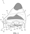
- an article of footwear 10 includes an upper 100 and a sole structure 200.
- the article of footwear 10 may be divided into one or more regions.
- the regions may include a forefoot region 12, a mid-foot region 14, and a heel region 16.
- the forefoot region 12 may be subdivided into a toe portion 12 T corresponding with phalanges, and a ball portion 12 B associated with metatarsal bones of a foot.
- a metatarsophalangeal (MTP) axis A MTP extends laterally across the article 10 along the intersection of the toe portion 12 T and the ball portion 12 B , and corresponds to an MTP joint of the foot. Accordingly, the article of footwear 10 is widest across the MTP axis A MTP .
- outward-most portions of the article of footwear 10 are disposed on the MTP axis A MTP .
- the mid-foot region 14 may correspond with an arch area of the foot, and the heel region 16 may correspond with rear portions of the foot, including a calcaneus bone.
- the footwear 10 may further include an anterior end 18 associated with a forward-most point of the forefoot region 12, and a posterior end 20 corresponding to a rearward-most point of the heel region 16.
- a longitudinal axis A 10 of the footwear 10 extends along a length of the footwear 10 from the anterior end 18 to the posterior end 20, parallel to a ground surface.
- the longitudinal axis A 10 is centrally located along the length of the footwear 10, and generally divides the footwear 10 into a lateral side 22 and a medial side 24. Accordingly, the lateral side 22 and the medial side 24 respectively correspond with opposite sides of the footwear 10 and extend through the regions 12, 14, 16.
- a longitudinal direction refers to the direction extending from the anterior end 18 to the posterior end 20, while a lateral direction refers to the direction transverse to the longitudinal direction and extending from the lateral side 22 to the medial side 24.
- the upper 100 includes interior surfaces that define an interior void 102 configured to receive and secure a foot for support on the sole structure 200.
- An ankle opening in the heel region 16 may provide access to the interior void 102.
- the ankle opening may receive a foot to secure the foot within the void 102 and to facilitate entry and removal of the foot from and to the interior void 102.
- the upper 100 may be formed from one or more materials that are stitched or adhesively bonded together to form the interior void 102. Suitable materials of the upper may include, but are not limited to, mesh, textiles, foam, leather, and synthetic leather. The materials may be selected and located to impart properties of durability, air-permeability, wear-resistance, flexibility, and comfort.
- the upper 100 includes a strobel 104 having a bottom surface 106 opposing the sole structure 200 and an opposing top surface 108 defining a footbed of the interior void 102.
- the strobel 104 is attached to the upper 100 using stitching or adhesives.
- the upper 100 is formed as a unitary boot or sock, wherein the strobel 104 and the upper 100 are unitarily formed of a knitted material.
- the footbed defined by the top surface 108 may be contoured to conform to a profile of the bottom surface (e.g., plantar) of the foot.
- the upper 100 may also incorporate additional layers such as one or more support plates 110, and an insole 112 or sockliner that may be disposed upon the strobel 104 and reside within the interior void 102 of the upper 100 to receive a plantar surface of the foot to enhance the comfort of the article of footwear 10.
- additional layers such as one or more support plates 110, and an insole 112 or sockliner that may be disposed upon the strobel 104 and reside within the interior void 102 of the upper 100 to receive a plantar surface of the foot to enhance the comfort of the article of footwear 10.
- one or more fasteners extend along the upper 100 to adjust a fit of the interior void 102 around the foot and to accommodate entry and removal of the foot therefrom.
- the upper 100 may include apertures, such as eyelets and/or other engagement features such as fabric or mesh loops that receive the fasteners.
- the fasteners may include laces, straps, cords, hook-and-loop, or any other suitable type of fastener.
- the upper 100 may include a tongue portion that extends between the interior void 102 and the fasteners.
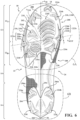
- the sole structure 200 is attached to the bottom surface 106 of the strobel 104 and includes a forefoot plate 202 disposed in the forefoot region 12 and a separate heel plate 204 disposed in the heel region 16. Accordingly, the mid-foot region 14 of the strobel 104 may be exposed between the forefoot plate 202 and the heel plate 204.
- the forefoot plate 202 and the heel plate 204 each include a plurality of ground-engaging members, which are configured to engage a soft or resilient ground surface.
- Each of the forefoot plate 202 and the heel plate 204 are formed of one or more rigid or semi-rigid materials.
- the forefoot plate 202 and the heel plate 204 are formed of one or more polymeric materials. In other examples, one or both of the forefoot plate 202 and the heel plate 204 may include a composite material, such as a fiber-reinforced composite material.
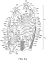
- the forefoot plate 202 includes a top surface 206 ( FIG. 7 ) attached to the bottom surface 106 of the upper 100, a bottom surface 208 formed on an opposite side of the forefoot plate 202 from the top surface 206, and a peripheral side surface 210 extending between the top surface 206 and the bottom surface 208 and defining an outer peripheral profile of the forefoot plate 202.
- the heel plate 204 includes a top surface (not shown) attached to the bottom surface 106 of the upper 100, a bottom surface 214 formed on an opposite side of the forefoot plate 202 from the top surface, and a peripheral side surface 216 extending between the top surface and the bottom surface 208 and defining an outer peripheral profile of the heel plate 204.
- the forefoot plate 202 and the heel plate 204 are spaced apart from each other in the midfoot region 14 such that the bottom surface 106 of the upper 100 is exposed through the mid-foot region 14. Accordingly, the bottom surface 208 of the forefoot plate 202, the bottom surface 106 of the upper 100, and the bottom surface 214 of the heel plate 204 cooperate to define a ground-engaging surface 26 of the article of footwear 10.
- the peripheral side surface 210 of the forefoot plate 202 includes a lateral portion 210a extending along the lateral side 22 of the upper 100 from the mid-foot region 14 to the anterior end 18, a medial portion 210b extending along the medial side 24 of the upper from the mid-foot region 14 to the anterior end 18, and a mid-foot portion 210c connecting the lateral portion 210a and the medial portion 210b across the mid-foot region 14.
- the lateral portion 210a of the peripheral side surface 210 may define a notch 218 on the lateral side 22 of the forefoot plate 202.
- the notch 218 is disposed in the toe portion 12 T , intermediate the MTP axis A MTP and the anterior end 18.
- the notch 218 extends inwardly from the lateral side 22 along a notch axis A 218 formed at an oblique angle with respect to the longitudinal axis A 10 of the footwear 10.
- the longitudinal axis A 218 extends inwardly and towards the posterior end 20 of the footwear 10.
- a width of the notch 218 may be tapered along the direction of the notch axis A 218 .
- the mid-foot portion 210c of the peripheral side surface 210 may form a cut-out 220 at a posterior end of the forefoot plate 202, between the lateral portion 210a and the medial portion 210b.
- the cut-out 220 has a polygonal shape defined by a plurality of straight segments of the mid-foot portion 210c.
- the cut-out 220 may be arcuate, or a combination of arcuate and polygonal.
- the bottom surface 208 of the forefoot plate 202 includes a plurality of traction elements including a pair of peripheral traction elements 222a, 222b and one or more directional traction elements 224a-224f.
- the forefoot plate 202 may further include at least one serrated region 226a, 226b formed in an interior portion of the bottom surface 208.
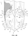
- the peripheral traction elements 222a, 222b include a lateral peripheral traction element 222a disposed adjacent to an outward-most portion of the article of footwear 10 on the lateral side 22, and a medial peripheral traction element 222b disposed adjacent to an outward-most portion of the article of footwear 10 on the medial side 22. Accordingly, the lateral peripheral traction element 222a and the medial peripheral traction element 222b are aligned with each other along the MTP axis A 218 , such that the peripheral traction elements 222a, 222b are disposed on opposite sides of the widest portion of the footwear 10.
- the lateral peripheral traction element 222a is disposed adjacent to an outward-most portion of the upper 100 on the lateral side 22 of the forefoot plate 202
- the medial peripheral traction element 222b is disposed adjacent to an outward-most portion of the upper 100 on the medial side 24 of the forefoot plate 202.
- the medial peripheral traction element 222b may be offset from the lateral peripheral traction element 222a along the longitudinal axis A 10 such that the medial peripheral traction element 222b is disposed closer to the anterior end 18 than the lateral peripheral traction element 222a, as shown in FIG. 6 .
- Each of the peripheral traction elements 222a, 222b includes a central stud 228a, 228b, an anterior blade 230a, 230b extending from the central stud 228a, 228b towards the anterior end 18, and a posterior blade 232a, 230b extending in an opposite direction from the central stud 228a, 228b towards the posterior end 20.
- the central stud 228a, 228b extends from a proximal end 234a, 234b attached to the bottom surface 208 to a terminal, distal end 236a, 236b facing away from the bottom surface 208.
- each of the central studs 228a, 228b includes an outer surface 238a, 238b, a posterior surface 240a, 240b, and an inner surface 242a, 242b that cooperate to define a substantially triangular cross-sectional shape of each of the central studs 228a, 228b.
- One or both of the central studs 228a, 228b may taper along a direction from the proximal end 234a, 234b to the distal end 236a, 236b, whereby a cross-sectional area of the distal end 236a, 236b is less than a cross-sectional area of the proximal end 234a, 234b.
- the outer surfaces 238a, 238b of each of the studs 228a, 228b extend from the peripheral side surface 210 of the forefoot plate 202 such that the central studs 228a, 228b form a portion of the outer peripheral of the forefoot plate 202.
- the posterior surface 232b of the central stud 228b on the medial side 24 may be concave, while the posterior surface 232a of the central stud 228a on the lateral side 22 is substantially planar.
- each of the anterior blades 230a, 230b includes a first end 244a, 244b attached to an anterior end of the central stud 228a, 228b and a terminal end 246a, 246b disposed between the central stud 228a, 228b and the anterior end 18. Accordingly, a length of each of the anterior blades 230a, 230b extends from the first end 244a, 244b at the central stud 228, and towards the anterior end 18 of the article of footwear 10 to the terminal end 246a, 246b.
- a height of the anterior blades 230a, 230b extends from a base 248a, 248b attached to the bottom surface 208 of the forefoot plate 202 to a distal edge 250a, 250b facing away from the bottom surface 208.
- the heights of the anterior blades 230a, 230b taper along the lengthwise direction of each of the anterior blades 230a, 230b, from the first end 244a, 244b to the terminal end 246a, 246b.
- the distal edge 250a, 250b may have a concave profile from the first end 244a, 244b to the terminal end 246a, 246b.
- each of the anterior blades 230a, 230b includes an outer surface 252a, 252b facing an outer periphery of the article 10, and an inner surface 254a, 254b formed on an opposite side of the anterior blade 230a, 230b from the outer surface 252a, 252b.
- the outer surface 252a, 252b and the inner surface 254a, 254b may converge with each other in the lengthwise direction from the first end 244a, 244b to the terminal end 246a, 246b.
- the outer surface 252a, 252b and the inner surface 254a, 254b may converge with each other in in the height direction from the base 248a, 248b to the distal edge 250a, 250b.
- widths of the anterior blades 230a, 230b taper along the length direction and the height direction.
- the outer surface 252a, 252b and the inner surface 254a, 254b intersect with each other at the distal edge 250a, 250b, such that the distal edge 250a, 250b forms a sharp edge extending continuously from the first end 244a, 244b to the terminal end 246a, 246b.
- each of the posterior blades 232a, 232b includes a first end 256a, 256b attached to an posterior end of the central stud 228a, 228b and a terminal end 258a, 258b disposed between the central stud 228a, 228b and the posterior end 20 in the forefoot region 12. Accordingly, a length of each of the posterior blades 232a, 232b extends from the first end 256a, 256b at the central stud 228, and towards the posterior end 20 of the article of footwear 10 to the terminal end 258a, 258b.
- a height of the posterior blades 232a, 232b extends from a base 260a, 260b attached to the bottom surface 208 of the forefoot plate 202 to a distal edge 262a, 262b facing away from the bottom surface 208.
- the heights of the posterior blades 232a, 232b taper along the lengthwise direction of each of the posterior blades 232a, 232b, from the first end 256a, 256b to the terminal end 258a, 258b.
- the distal edge 262a, 262b may have a concave profile from the first end 256a, 256b to the terminal end 258a, 258b.
- each of the posterior blades 232a, 232b includes an outer surface 264a, 264b facing an outer periphery of the article of footwear 10, and an inner surface 266a, 266b formed on an opposite side of the posterior blade 232a, 232b from the outer surface 264a, 264b.
- the outer surface 264a, 264b and the inner surface 266a, 266b may converge with each other in the lengthwise direction from the first end 256a, 256b to the terminal end 258a, 258b.
- the outer surface 264a, 264b and the inner surface 266a, 266b may converge with each other in the height direction from the base 260a, 260b to the distal edge 262a, 262b. Accordingly, widths of the posterior blades 232a, 232b may taper along the length direction and the height direction. As shown, the outer surface 264a, 264b and the inner surface 266a, 266b intersect with each other at the distal edge 262a, 262b, such that the distal edge 262a, 262b forms a sharp, knife-like edge extending continuously from the first end 256a, 256b to the terminal end 258a, 258b.
- the outer surfaces 238a, 252a, 264a of the lateral peripheral cleat 222a are continuously formed with each other, and cooperate to form a substantially continuous convex surface facing the lateral portion 210a of the outer peripheral side surface 210.
- the outer surfaces 238b, 252b, 264b of the medial peripheral cleat 222b are continuously formed with each other, and cooperate to form a substantially continuous convex surface facing the medial portion 210b of the peripheral side surface 210.
- the inner surfaces 254a, 254b of the anterior blades 230a, 230b intersect the inner surfaces 240a, 240b of the respective central studs 228a, 228b to form substantially continuous convex surfaces at anterior portions of the peripheral cleats 222a, 222b.
- the inner surfaces 264a, 264b of the posterior blades 232a, 232b intersect the posterior surfaces 242a, 242b of the respective central studs 228a, 228b to form substantially continuous convex surfaces at posterior portions of the peripheral cleats 222a, 222b.
- the intersection between the inner surface 254a of the anterior blade 230a and the inner surface 240a of the central stud 228a has a first radius R 230a
- the intersection between the inner surface 266a of the posterior blade 232a and the posterior surface 242a of the central stud 228a has a second radius R 232a
- the first radius R 230a may be larger than the second radius R 232a such that a transition from the inner surface 254a of the anterior blade 230a and the inner surface 240a of the central stud 228a is more gradual than the transition from the inner surface 266a of the posterior blade 232a and the posterior surface 242a of the central stud 228a.
- the intersection between the inner surface 254b of the anterior blade 230b and the inner surface 240b of the central stud 228b has a first radius R 230b
- the intersection between the inner surface 266b of the posterior blade 232b and the posterior surface 242b of the central stud 228b has a second radius R 232b
- the first radius R 230b may be larger than the second radius R 232b such that a transition from the inner surface 254b of the anterior blade 230b and the inner surface 240b of the central stud 228b is more gradual than the transition from the inner surface 266b of the posterior blade 232b and the posterior surface 242b of the central stud 228b.
- the distal edges 250a, 262a of the lateral peripheral cleat 222a extend substantially parallel to the curvature of the lateral portion 210a of the peripheral side surface.
- the distal edges 250b, 262b of the medial peripheral cleat 222b may extend at an oblique angle relative to the peripheral side surface 210.
- the distal edges 250b, 262b of the anterior blade 230b and the posterior blade 232b may diverge from the peripheral side surface 210 along the lengthwise direction from the first end 244b, 256b to the terminal end 246b, 258b.
- the forefoot plate 202 includes one or more directional cleats 224a-224f.
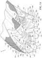
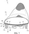
- Each of the directional cleats 224a-224f extends from a base 268a-268f attached to the bottom surface 208 of the forefoot plate 202 to a distal tip 270a-270f facing away from the bottom surface 208, as best shown in FIG. 1A .
- the distal tip 270a-270f is substantially planar.
- the cross-sectional shape of one or more of the directional cleats 224a-224f may transition from a chevron having rounded sides at the base 268a-268f to a chevron having straight sides at the distal tip 270a-270f.
- first leg 272a-272f and the second leg 274a-274f cooperate to define a convex or pointed leading face 278a-278f and a concave or cupped trailing face 280a-280f formed on an opposite side of the directional cleat 224a-224f from the leading face 278a-278f.
- the leading face 278a-278f may include a leading edge formed along the central portion 276a-276f from the base 268a-268f to the tip 270a-270f.
- the forefoot plate 202 includes a first directional cleat 224a located adjacent to the anterior end 18 of the sole structure 200, with the leading face 278a facing towards the anterior end 18.
- a second directional cleat 224b is located in the toe portion 12 T adjacent to the medial portion 210b of the peripheral side surface 210.
- a third directional cleat 224c is located in the toe portion 12 T , laterally across from the second directional cleat 224b and adjacent to the lateral portion 210a of the peripheral side surface 210.
- the second directional cleat 224b is located adjacent to and forward of (i.e., towards the anterior end 18) the notch 218, with the leading face 278b oriented forward and towards the lateral side 22.
- a fourth directional cleat 224d is located in the toe portion 12 T on the lateral side 22, adjacent to the anterior blade 230a of the lateral peripheral cleat 222a.
- the leading face 278d of the fourth directional cleat 224d is oriented towards the anterior end 18.
- the forefoot plate may include fifth and sixth directional cleats 224e, 224f located in the ball portion 12 B .
- the fifth directional cleat 224e is disposed in the ball portion 12 B on the medial side 24 of the forefoot plate 202, adjacent to the posterior blade 232b of the medial peripheral cleat 222b.
- the leading face 278e of the fifth directional cleat 224e is oriented rearward (i.e., towards the posterior end 20) and towards the medial side 24.
- the sixth directional cleat 224f is positioned on the lateral side of the ball portion 12 B , adjacent to the posterior blade 232a of the lateral peripheral cleat 222a.
- the leading face 278f of the sixth directional cleat 224f is oriented rearward and towards the lateral portion 210a of the peripheral side surface 210.
- the forefoot plate 202 may also include one or more serrated regions 226a, 226b formed on an interior portion of the bottom surface 208.
- Each of the serrated regions 226a, 226b includes a plurality of elongate ribs 282a, 282b arranged in series along a direction of the longitudinal axis A 10 .
- a length of each of the ribs 282a, 282b extends continuously from a first end 284a, 284b to a second end 286a, 286b, while a height of each of the ribs 282a, 282b extends from the bottom surface 208 of the forefoot plate to a distal edge 288a, 288b.
- the height of each of the ribs 282a, 282b tapers along the length from a central portion to at least one of the first end 284a, 284b and the second end 286a, 286b, whereby a height of each rib 282a, 282b is greater in the middle.
- the height of the ribs 282a, 282b may taper continuously to each end 284a, 284b, 286a, 286b so that the distal edge 288a, 288b intersects the bottom surface 208 of the forefoot plate 202.
- each of the ribs 282a, 282b may extend along an arcuate path and include a concave inner surface 290a, 290b and a convex outer surface 292a, 292b.
- adjacent ones of the ribs 282a, 282b may be substantially parallel to provide a series of arcuate ribs 282a, 282b arranged along the bottom surface 208.
- lengths of successive ones of the ribs 282a, 282b may progressively increase from a first end (facing the concave inner surfaces) of the serrated region 226a, 226b to a second end (facing the convex outer surfaces) of the serrated region 226a, 226b.
- lengths of ribs 282a, 282b closer to the first end of the serrated region 226a, 226b will be shorter than ribs 282a, 282b closer to the second end of the serrated region 226a, 226b.
- the serrated regions 226a, 226b may be described as having an overall width that tapers along the direction from the first end to the second end, whereby the lengths of the ribs 282a, 282b become successively shorter.
- a first serrated region 226a is positioned on the lateral side 22 of the forefoot plate 202 in the ball portion 12 B .
- the first serrated region 226a is positioned adjacent to the trailing face 280f of the sixth directional cleat 224f and an inside edge of the central stud 228a of the lateral peripheral cleat 222a.
- the first serrated region 226a is also disposed between the trailing face 280f of the sixth directional cleat 224f and the trailing face 280d of the fourth directional cleat 224d.
- the concave inner surfaces 290a of the ribs 282a face the anterior end of the forefoot plate 202. Accordingly, an overall width (i.e. lengths of the ribs 282a) of the first serrated region 226a tapers along the direction from the posterior end 20 to the anterior end 18.
- a second serrated region 226b is positioned on the medial side 24 of the forefoot plate 202 and extends from a first end in the ball portion 12 B to a second end in the toe portion 12 T .
- the first end is disposed adjacent to the trailing face 280e of the fifth directional traction element 224e and the second end is adjacent to the second directional traction element 224b and the third directional traction element 224c.
- an overall width (i.e. lengths of the ribs 282b) of the second serrated region 226b tapers along the direction from the anterior end 18 to the posterior end 20.
- the heel plate 204 of the sole structure 200 is located in the heel region 16 adjacent to the posterior end 20.
- the peripheral side surface 216 of the heel plate 204 may define a notch 294 in an anterior end of the heel plate 204, which divides the anterior end of the heel plate 204 into lateral and medial lobes 296a, 296b.
- the notch 294 tapers in width from the anterior end of the heel plate 204 to a central portion of the heel plate 204.
- the heel plate 204 includes a central spine 298 extending from a first end 300 at the notch 294 to a second end 302 at the posterior end 20 of the article of footwear 10 along the longitudinal axis A 10 .
- the spine 298 may include a cleat 304 formed in an intermediate portion thereof.
- the cleat 304 is formed where a first portion 298a of the spine 298 that extends longitudinally along the bottom surface 214 of the heel plate 204 intersects a second portion 298b of the spine 298 that extends vertically along the posterior end 20 of the heel plate 204.
- a thickness of the first portion 298a continuously increases along a direction from the first end 300 of the spine 298 and a thickness of the second portion 298b continuously increases along a direction from the second end 302 of the spine 298. Accordingly, the cleat 304 is formed at the thickest portion of the spine 298, where the first portion 298a and the second portion 298b converge.
- the heel plate 204 includes one or more directional cleats 224g-224j.
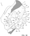
- Each of the directional cleats 224g-224j extends from a base 268g-268j attached to the bottom surface 208 of the forefoot plate 202 to a distal tip 270g-270j facing away from the bottom surface 208, as best shown in FIG. 1B .
- the distal tip 270g-270j is substantially planar.
- Each of the directional cleats 224g-224j has a generally chevron-shaped configuration including a first leg 272g-272j and a second leg 274g-274j extending in opposite directions from a central portion 276g-276j to respective distal ends.
- the size and/or shape of one or more of the directional cleats 224g-224j may transition along the direction from the base 268g-268j to the distal tip 270g-270j.
- the directional cleats 224g-224j may be tapered from the base 268g-268j to the distal tip 270g-270j.
- the cross-sectional shape of one or more of the directional cleats 224g-224j may transition from a chevron having rounded sides at the base 268g-268j to a chevron having straight sides at the distal tip 270g-270j.
- first leg 272g-272j and the second leg 274g-274j cooperate to define a convex or pointed leading face 278g-278j and a concave or cupped trailing face 280g-280j formed on an opposite side of the directional cleat 224g-224j from the leading face 278g-278j.
- the leading face 278g-278j may include a leading edge formed along the central portion 276a-276j from the base 268g-268j to the tip 270g-270j.
- the heel plate 204 includes a first pair of forward facing directional cleats 224g, 224h, including a seventh directional cleat 224g located on the lateral lobe 296a and an eighth directional cleat 224h located on the medial lobe 296b. Accordingly, the forward facing directional cleats 224g, 224h are disposed on opposite sides of the notch 294.
- the leading face 278g of the seventh directional cleat 224g is oriented at an oblique angle relative to the longitudinal axis A 10 such that the central portion 276g points towards the lateral side 22 and the anterior end 18 of the article of footwear 10.
- the leading face 278h of the eighth directional cleat 224h is oriented at an oblique angle relative to the longitudinal axis A 10 , in an opposite direction of the seventh directional cleat 224g. Accordingly, the central portion 276h of the eighth directional cleat 224h points towards the medial side 24 and the anterior end 18 of the article of footwear 10.
- the heel plate 204 also includes a pair of rearward facing directional cleats 224i, 224j, including a ninth directional cleat 224i and a tenth directional cleat 224j.
- the ninth directional cleat 224i is located adjacent to the peripheral side surface 216 on the lateral side 22 at the posterior end 20.
- the leading face 278i of the ninth directional cleat 224i is oriented at an oblique angle relative to the longitudinal axis A 10 such that the central portion 276i points towards the lateral side 22 and the posterior end 20 of the article of footwear 10.
- the tenth directional cleat 224j is located adjacent to the peripheral side surface 216 on the medial side 24 at the posterior end 20.
- the leading face 278j of the tenth directional cleat 224j is oriented at an oblique angle relative to the longitudinal axis A 10 such that the central portion 276j points towards the medial side 24 and the posterior end 20 of the article of footwear 10.
- the directional cleats 224g-224j of the heel plate 204 are radially arranged about a central portion of the heel plate 204 such that the concave or cupped trailing faces 280g-280j of the directional cleats 224g-224j face each other. Accordingly, the trailing faces 280g-280j cooperate to define a rotational track in the heel region 16 of the article of footwear, whereby the trailing faces engage the ground surface and follow a substantially similar rotational path as the user rotates the foot about the heel portion 16.
- the chevron-shaped directional cleats 224g-224j provide traction in the longitudinal and lateral directions.
- the first legs 272g-272j and the second legs 274g-274j form ground engaging surfaces that are transverse to the forces applied when moving in the longitudinal and lateral directions, thereby preventing slippage of the heel plate 204 relative to the ground surface.
Landscapes
- Chemical & Material Sciences (AREA)
- Engineering & Computer Science (AREA)
- Materials Engineering (AREA)
- Footwear And Its Accessory, Manufacturing Method And Apparatuses (AREA)
Claims (10)
- Schuhwerk (10), umfassend:einen Schaft (100) mit einer unteren Oberfläche (106);eine erste Platte (202), befestigt an der unteren Oberfläche (106) des Schafts (100) in einem Vorderfußbereich (12) und einschließlich eines lateralen Randnockens (222a), der neben einem ersten äußersten Abschnitt des Schafts (100) auf einer lateralen Seite (22) angeordnet ist, und eines medialen Randnockens (222b), der neben einem zweiten äußersten Abschnitt des Schafts (100) auf einer medialen Seite (24) angeordnet ist, wobei der mediale Randnocken (222b) näher an einem vorderen Ende der ersten Platte (202) angeordnet ist als der laterale Randnocken (222a); undeinen ersten gezackten Bereich (226a, 226b), angeordnet zwischen dem lateralen Randnocken (222a) und dem medialen Randnocken (222b), und einschließlich einer Vielzahl von länglichen ersten Rippen (282a, 282b), die sich von einer unteren Oberfläche (208) der ersten Platte (202) aus erstrecken,wobeijeder der Randnocken (222a, 222b) einschließt: einen Stift (228a, 228b) mit einer im Wesentlichen dreieckigen Querschnittsform, ein erstes Blatt (230a, 230b), das sich entlang einer ersten Längsrichtung von einem ersten Ende (244a, 244b), angebracht an einem vorderen Ende des Stifts (228a, 228b), hin zu einem Abschlussende (246a, 246b), angeordnet zwischen dem Stift (228a, 228b) und einem vorderen Ende (18), erstreckt, und ein zweites Blatt (232a, 232b), das sich entlang einer zweiten Längsrichtung von einem ersten Ende (256a, 256b), angebracht an einem hinteren Ende des Stifts (228a, 228b), hin zu einem Abschlussende (258a, 258b), angeordnet zwischen dem Stift (228a, 228b) und einem hinteren Ende (20), erstreckt, undäußere Oberflächen (238a, 238b, 252a, 252b, 264a, 264b) des Stifts (228a, 228b), des ersten Blatts (230a, 230b) und des zweiten Blatts (232a, 232b) eine im Wesentlichen durchgehende äußere Oberfläche ausbilden.
- Schuhwerk (10) nach Anspruch 1, wobei der erste äußerste Abschnitt des Schafts (100) und der zweite äußerste Abschnitt des Schafts (100) entlang einer Metatarsophalangealachse (AMTP) ausgerichtet sind.
- Schuhwerk (10) nach Anspruch 1, wobei jeder Stift (228a, 228b) der Randnocken (222a, 222b) am jeweils äußersten Abschnitt des Schafts (100) angeordnet ist.
- Schuhwerk nach Anspruch 3, wobei der Stift (228a, 228b) eine nach außen weisende Oberfläche einschließt, die neben einer Umfangsoberfläche der ersten Platte (202) angeordnet ist.
- Schuhwerk (10) nach Anspruch 1, wobei die ersten Rippen (282a, 282b) der Vielzahl von länglichen ersten Rippen (282a, 282b) eine bogenförmige Form einschließen.
- Schuhwerk (10) nach Anspruch 1, wobei die ersten Rippen (282a, 282b) der Vielzahl von länglichen ersten Rippen (282a, 282b) eine konkave Oberfläche (290a, 290b), die auf einer ersten Seite jeder ersten Rippe (282a, 282b) ausgebildet ist, und eine konvexe Oberfläche (292a, 292b), die auf einer gegenüberliegenden Seite jeder ersten Rippe (282a, 282b) ausgebildet ist, einschließen.
- Schuhwerk (10) nach Anspruch 6, wobei die konkave Oberfläche (290a) jeder ersten Rippe (282a) zu dem vorderen Ende der ersten Platte (202) weist.
- Schuhwerk nach Anspruch 6, wobei die konkave Oberfläche (290b) jeder ersten Rippe (282b) zu einem hinteren Ende der ersten Platte (202) weist.
- Schuhwerk (10) nach Anspruch 1, ferner umfassend einen zweiten gezackten Bereich (226a, 226b), angeordnet zwischen dem lateralen Randnocken (222a) und dem medialen Randnocken (222b), und einschließlich einer Vielzahl von länglichen zweiten Rippen (282a, 282b), die sich von der unteren Oberfläche (208) der ersten Platte (202) aus erstrecken.
- Schuhwerk nach Anspruch 9, wobei mindestens eine erste Rippe (282a) der Vielzahl von länglichen ersten Rippen (282a) eine erste konkave Oberfläche (290a) einschließt und mindestens eine zweite Rippe (282b) der Vielzahl länglicher zweiter Rippen eine zweite konkave Oberfläche (290b) einschließt, wobei die erste konkave Oberfläche (290a) zu dem vorderen Ende der ersten Platte (202) weist und die zweite konkave Oberfläche (290b) zu einem hinteren Ende der ersten Platte (202) weist.
Applications Claiming Priority (2)
| Application Number | Priority Date | Filing Date | Title |
|---|---|---|---|
| US201962855356P | 2019-05-31 | 2019-05-31 | |
| PCT/US2020/035155 WO2020243453A1 (en) | 2019-05-31 | 2020-05-29 | Sole structure for article of footwear |
Publications (2)
| Publication Number | Publication Date |
|---|---|
| EP3975784A1 EP3975784A1 (de) | 2022-04-06 |
| EP3975784B1 true EP3975784B1 (de) | 2024-09-18 |
Family
ID=73549854
Family Applications (1)
| Application Number | Title | Priority Date | Filing Date |
|---|---|---|---|
| EP20760606.2A Active EP3975784B1 (de) | 2019-05-31 | 2020-05-29 | Sohlenstruktur für schuhwerk |
Country Status (4)
| Country | Link |
|---|---|
| US (2) | US11627780B2 (de) |
| EP (1) | EP3975784B1 (de) |
| CN (1) | CN113950268B (de) |
| WO (1) | WO2020243453A1 (de) |
Families Citing this family (26)
| Publication number | Priority date | Publication date | Assignee | Title |
|---|---|---|---|---|
| USD1037630S1 (en) * | 2019-01-28 | 2024-08-06 | Adidas Ag | Shoe |
| USD966678S1 (en) * | 2019-10-11 | 2022-10-18 | Adidas Ag | Shoe |
| USD940444S1 (en) * | 2020-03-12 | 2022-01-11 | Puma SE | Shoe sole |
| USD971571S1 (en) * | 2020-04-09 | 2022-12-06 | Under Armour, Inc. | Sole structure |
| USD937550S1 (en) | 2020-07-24 | 2021-12-07 | Nike, Inc. | Shoe |
| USD931590S1 (en) * | 2020-07-24 | 2021-09-28 | Nike, Inc. | Shoe |
| USD954411S1 (en) | 2020-07-24 | 2022-06-14 | Nike, Inc. | Shoe |
| USD962622S1 (en) | 2020-10-23 | 2022-09-06 | Nike, Inc. | Shoe |
| USD990132S1 (en) * | 2021-02-26 | 2023-06-27 | Nike, Inc. | Shoe |
| USD990117S1 (en) * | 2021-02-26 | 2023-06-27 | Nike, Inc. | Shoe |
| USD1033844S1 (en) * | 2021-09-03 | 2024-07-09 | Nike, Inc. | Shoe |
| USD1033845S1 (en) * | 2021-09-03 | 2024-07-09 | Nike, Inc. | Shoe |
| USD1033846S1 (en) * | 2021-09-03 | 2024-07-09 | Nike, Inc. | Shoe |
| USD1032161S1 (en) * | 2021-12-22 | 2024-06-25 | Nike, Inc. | Shoe |
| USD1033833S1 (en) * | 2021-12-22 | 2024-07-09 | Nike, Inc. | Shoe |
| USD1031226S1 (en) * | 2021-12-22 | 2024-06-18 | Nike, Inc. | Shoe |
| USD973333S1 (en) * | 2022-03-31 | 2022-12-27 | Nike, Inc. | Shoe |
| USD980605S1 (en) * | 2022-05-13 | 2023-03-14 | Nike, Inc. | Shoe |
| USD1000793S1 (en) * | 2023-01-05 | 2023-10-10 | Nike, Inc. | Shoe |
| USD1000792S1 (en) * | 2023-01-05 | 2023-10-10 | Nike, Inc. | Shoe |
| USD1000794S1 (en) * | 2023-01-05 | 2023-10-10 | Nike, Inc. | Shoe |
| USD1000791S1 (en) * | 2023-01-05 | 2023-10-10 | Nike, Inc. | Shoe |
| USD1060983S1 (en) * | 2024-01-12 | 2025-02-11 | Nike, Inc. | Shoe |
| CN221616376U (zh) * | 2024-01-24 | 2024-08-30 | 深圳市艾克体育用品有限公司 | 鞋底及鞋子 |
| USD1102112S1 (en) * | 2024-02-29 | 2025-11-18 | Puma SE | Shoe sole |
| USD1106662S1 (en) * | 2024-06-21 | 2025-12-23 | Nike, Inc. | Shoe |
Family Cites Families (58)
| Publication number | Priority date | Publication date | Assignee | Title |
|---|---|---|---|---|
| AT342455B (de) * | 1971-09-15 | 1978-04-10 | Dassler Puma Sportschuh | Schuhsohle fur sportschuhe |
| US4173083A (en) * | 1978-01-16 | 1979-11-06 | Riddell, Inc. | Athletic shoe construction |
| AR228821A1 (es) * | 1982-02-22 | 1983-04-15 | Dassler Puma Sportschuh | Calzado deportivo |
| US4670997A (en) * | 1984-03-23 | 1987-06-09 | Stanley Beekman | Athletic shoe sole |
| US4641438A (en) * | 1984-11-15 | 1987-02-10 | Laird Bruce A | Athletic shoe for runner and joggers |
| DE8618748U1 (de) * | 1986-07-12 | 1986-10-09 | adidas Sportschuhfabriken Adi Dassler Stiftung & Co KG, 8522 Herzogenaurach | Golfschuhsohle |
| FR2632497A1 (fr) * | 1988-03-22 | 1989-12-15 | Beneteau Charles Marie | Semelle de chaussures pour la pratique des sports et activites analogues |
| US4914838A (en) * | 1988-08-18 | 1990-04-10 | Ringor Inc. | Sport shoe with metatarsal cradle and drag toe |
| US5461801A (en) * | 1993-08-18 | 1995-10-31 | Anderton; Graeme | Cleated athletic shoe with crisscross arch reinforcement |
| US5862614A (en) * | 1997-01-31 | 1999-01-26 | Nine West Group, Inc. | Indoor exercise shoe and sole therefor |
| DE19957821A1 (de) * | 1999-12-01 | 2001-06-28 | Adidas Int Bv | Sohle |
| JP3831686B2 (ja) * | 2001-06-07 | 2006-10-11 | 美津濃株式会社 | スポーツシューズのソール組立体 |
| DE60110053T2 (de) * | 2001-06-11 | 2005-09-08 | Calzaturificio S.C.A.R.P.A. S.P.A., Asolo | Sohle für Sportschuh |
| FR2832296B1 (fr) * | 2001-11-21 | 2004-04-02 | Salomon Sa | Semelle de chaussure |
| US7143529B2 (en) * | 2002-01-14 | 2006-12-05 | Acushnet Company | Torsion management outsoles and shoes including such outsoles |
| US6708426B2 (en) * | 2002-01-14 | 2004-03-23 | Acushnet Company | Torsion management outsoles and shoes including such outsoles |
| US6817117B1 (en) * | 2002-03-05 | 2004-11-16 | Nike, Inc. | Golf shoe outsole with oriented traction elements |
| US6857205B1 (en) * | 2002-05-09 | 2005-02-22 | Nike, Inc. | Article of footwear having a sole structure with a split plate |
| US6892479B2 (en) * | 2002-06-26 | 2005-05-17 | Nike, Inc. | Article of cleated footwear having medial and lateral sides with differing properties |
| US20040181974A1 (en) * | 2003-03-20 | 2004-09-23 | Robinson Douglas K. | Dual density thermoplastic urethane saddle shoe |
| US8215035B2 (en) * | 2003-11-06 | 2012-07-10 | Elan-Polo, Inc. | Athletic shoe having an improved cleat arrangement and improved cleat |
| AU2005271918B2 (en) * | 2004-07-12 | 2010-08-12 | Cleats Llc | Removable footwear traction plate |
| US7594345B2 (en) * | 2005-10-12 | 2009-09-29 | Nike, Inc. | Article of footwear having sole with ribbed structure |
| US20080098624A1 (en) * | 2006-10-26 | 2008-05-01 | Under Armour, Inc. | Athletic shoe for improved traction and rotational movement |
| US7845097B2 (en) * | 2006-12-07 | 2010-12-07 | Callaway Golf Company | Chemically-treated outsole assembly for a golf shoe |
| US7954258B2 (en) * | 2007-10-17 | 2011-06-07 | Nike, Inc. | Article of footwear with walled cleat system |
| US7941945B2 (en) * | 2007-10-17 | 2011-05-17 | Nike, Inc. | Article of footwear with heel traction elements |
| US20090211118A1 (en) * | 2008-02-26 | 2009-08-27 | Softspikes, Llc | Traction Cleat for Field Sports |
| DE102008064493A1 (de) | 2008-12-23 | 2010-06-24 | Adidas International Marketing B.V. | Sohle |
| CN102421316B (zh) * | 2009-04-02 | 2015-11-25 | 耐克创新有限合伙公司 | 附着力元件 |
| US8356428B2 (en) * | 2009-10-20 | 2013-01-22 | Nike, Inc. | Article of footwear with flexible reinforcing plate |
| US10681955B2 (en) | 2011-03-08 | 2020-06-16 | Ot Intellectual Property, Llc | Interchangeable sole system |
| US8997381B2 (en) * | 2011-08-29 | 2015-04-07 | Nike, Inc. | Interchangeable cleat system for footwear |
| US9138027B2 (en) * | 2011-09-16 | 2015-09-22 | Nike, Inc. | Spacing for footwear ground-engaging member support features |
| US9173450B2 (en) * | 2011-09-16 | 2015-11-03 | Nike, Inc. | Medial rotational traction element arrangement for an article of footwear |
| US9314065B2 (en) * | 2012-06-15 | 2016-04-19 | Nike, Inc. | Article of footwear with base plate having structure and studs |
| US9609915B2 (en) * | 2013-02-04 | 2017-04-04 | Nike, Inc. | Outsole of a footwear article, having fin traction elements |
| US9179738B2 (en) * | 2012-11-05 | 2015-11-10 | Taylor Made Golf Company, Inc. | Golf shoes |
| US9414642B2 (en) * | 2013-01-22 | 2016-08-16 | Nike, Inc. | Cleated footwear |
| WO2014155707A1 (ja) * | 2013-03-29 | 2014-10-02 | 株式会社アシックス | 可動性クリートを有する靴 |
| US20150096195A1 (en) * | 2013-10-08 | 2015-04-09 | Acushnet Company | Golf shoes having outsoles with sections of differing hardness |
| US9420851B2 (en) * | 2013-12-31 | 2016-08-23 | Nike, Inc. | Footwear having lace receiving strands |
| US10123588B2 (en) * | 2013-12-31 | 2018-11-13 | Nike, Inc. | Footwear ground engaging members having concave portions |
| US20150359294A1 (en) * | 2014-06-17 | 2015-12-17 | Nike, Inc. | Multi-Rubber Outsole |
| US20160021977A1 (en) * | 2014-07-22 | 2016-01-28 | Nike, Inc. | Sole structure for an article of footwear including a shank |
| US9681702B2 (en) * | 2014-08-22 | 2017-06-20 | Nike, Inc. | Footwear with elongated cleats |
| US9681703B2 (en) * | 2014-12-09 | 2017-06-20 | Nike, Inc. | Footwear with flexible auxetic sole structure |
| US9820529B2 (en) * | 2015-02-20 | 2017-11-21 | Nike, Inc. | Asymmetric torsion plate and composite sole structure for article of footwear |
| US10244815B2 (en) * | 2015-08-25 | 2019-04-02 | Nike, Inc. | Footwear sole structure with carrier and frame |
| WO2017079249A1 (en) * | 2015-11-05 | 2017-05-11 | Nike Innovate C.V. | Sole structure for an article of footwear having a nonlinear bending stiffness with compression grooves and descending ribs |
| US9591891B1 (en) | 2015-12-07 | 2017-03-14 | Nike, Inc. | Article having sole assembly with cleats |
| US10842223B2 (en) * | 2016-01-15 | 2020-11-24 | Nike, Inc. | Footwear with internal chassis and/or indexed sock liner |
| US20180084862A1 (en) * | 2016-09-23 | 2018-03-29 | Acushnet Company | Golf shoe with an outsole having a skeletal frame |
| US20180242688A1 (en) * | 2017-02-28 | 2018-08-30 | Nike, Inc. | Sole structure with chevron traction elements |
| US20190090585A1 (en) * | 2017-09-22 | 2019-03-28 | Wolverine Outdoors, Inc. | Sole assembly for article of footwear |
| US10492565B2 (en) * | 2017-10-06 | 2019-12-03 | Wolverine Outdoors, Inc. | Footwear with improved traction |
| WO2019204202A1 (en) * | 2018-04-16 | 2019-10-24 | Nike Innovate C.V. | Outsole plate |
| WO2019217561A1 (en) * | 2018-05-08 | 2019-11-14 | Tyler Reece Stuart | Footwear cleat |
-
2020
- 2020-05-29 EP EP20760606.2A patent/EP3975784B1/de active Active
- 2020-05-29 WO PCT/US2020/035155 patent/WO2020243453A1/en not_active Ceased
- 2020-05-29 US US16/887,395 patent/US11627780B2/en active Active
- 2020-05-29 CN CN202080040488.4A patent/CN113950268B/zh active Active
-
2023
- 2023-02-17 US US18/170,876 patent/US20230200495A1/en active Pending
Also Published As
| Publication number | Publication date |
|---|---|
| CN113950268B (zh) | 2024-01-12 |
| WO2020243453A1 (en) | 2020-12-03 |
| US20200375320A1 (en) | 2020-12-03 |
| CN113950268A (zh) | 2022-01-18 |
| EP3975784A1 (de) | 2022-04-06 |
| US11627780B2 (en) | 2023-04-18 |
| US20230200495A1 (en) | 2023-06-29 |
Similar Documents
| Publication | Publication Date | Title |
|---|---|---|
| EP3975784B1 (de) | Sohlenstruktur für schuhwerk | |
| US11039663B2 (en) | Footwear ground engaging members having concave portions | |
| CN109068798B (zh) | 具有自适应配合的鞋类物品 | |
| CN108497623B (zh) | 具有鞋带接纳绳的鞋类 | |
| EP2552268B1 (de) | Schuhartikel mit abnehmbarer hülle | |
| CN118076261A (zh) | 鞋类制品的外底花纹 | |
| US10258108B2 (en) | Article of footwear with tongue of varying thickness | |
| US20150289591A1 (en) | Modular Articles With Customizable Sole Inserts | |
| WO2016191275A1 (en) | Ground-engaging structures for articles of footwear | |
| CN118201521A (zh) | 鞋类制品 | |
| CN103167812B (zh) | 鞋 | |
| EP4176753A1 (de) | Sohlenstruktur für schuhwerk | |
| US20120317836A1 (en) | Method For Assembling A Tongue For An Article Of Footwear | |
| US11617422B2 (en) | Cleat structure for article of footwear | |
| EP4494511A2 (de) | Sohlenstruktur für schuhwerk | |
| EP4631383A1 (de) | Sohlenstruktur für schuhwerk | |
| CN116491738A (zh) | 用于鞋类物品的鞋底结构 |
Legal Events
| Date | Code | Title | Description |
|---|---|---|---|
| STAA | Information on the status of an ep patent application or granted ep patent |
Free format text: STATUS: UNKNOWN |
|
| STAA | Information on the status of an ep patent application or granted ep patent |
Free format text: STATUS: THE INTERNATIONAL PUBLICATION HAS BEEN MADE |
|
| PUAI | Public reference made under article 153(3) epc to a published international application that has entered the european phase |
Free format text: ORIGINAL CODE: 0009012 |
|
| STAA | Information on the status of an ep patent application or granted ep patent |
Free format text: STATUS: REQUEST FOR EXAMINATION WAS MADE |
|
| 17P | Request for examination filed |
Effective date: 20211202 |
|
| AK | Designated contracting states |
Kind code of ref document: A1 Designated state(s): AL AT BE BG CH CY CZ DE DK EE ES FI FR GB GR HR HU IE IS IT LI LT LU LV MC MK MT NL NO PL PT RO RS SE SI SK SM TR |
|
| DAV | Request for validation of the european patent (deleted) | ||
| DAX | Request for extension of the european patent (deleted) | ||
| P01 | Opt-out of the competence of the unified patent court (upc) registered |
Effective date: 20230515 |
|
| GRAP | Despatch of communication of intention to grant a patent |
Free format text: ORIGINAL CODE: EPIDOSNIGR1 |
|
| STAA | Information on the status of an ep patent application or granted ep patent |
Free format text: STATUS: GRANT OF PATENT IS INTENDED |
|
| INTG | Intention to grant announced |
Effective date: 20240419 |
|
| GRAS | Grant fee paid |
Free format text: ORIGINAL CODE: EPIDOSNIGR3 |
|
| GRAA | (expected) grant |
Free format text: ORIGINAL CODE: 0009210 |
|
| STAA | Information on the status of an ep patent application or granted ep patent |
Free format text: STATUS: THE PATENT HAS BEEN GRANTED |
|
| AK | Designated contracting states |
Kind code of ref document: B1 Designated state(s): AL AT BE BG CH CY CZ DE DK EE ES FI FR GB GR HR HU IE IS IT LI LT LU LV MC MK MT NL NO PL PT RO RS SE SI SK SM TR |
|
| REG | Reference to a national code |
Ref country code: GB Ref legal event code: FG4D |
|
| REG | Reference to a national code |
Ref country code: CH Ref legal event code: EP |
|
| REG | Reference to a national code |
Ref country code: IE Ref legal event code: FG4D |
|
| REG | Reference to a national code |
Ref country code: DE Ref legal event code: R096 Ref document number: 602020037964 Country of ref document: DE |
|
| REG | Reference to a national code |
Ref country code: LT Ref legal event code: MG9D |
|
| PG25 | Lapsed in a contracting state [announced via postgrant information from national office to epo] |
Ref country code: NO Free format text: LAPSE BECAUSE OF FAILURE TO SUBMIT A TRANSLATION OF THE DESCRIPTION OR TO PAY THE FEE WITHIN THE PRESCRIBED TIME-LIMIT Effective date: 20241218 |
|
| PG25 | Lapsed in a contracting state [announced via postgrant information from national office to epo] |
Ref country code: GR Free format text: LAPSE BECAUSE OF FAILURE TO SUBMIT A TRANSLATION OF THE DESCRIPTION OR TO PAY THE FEE WITHIN THE PRESCRIBED TIME-LIMIT Effective date: 20241219 Ref country code: FI Free format text: LAPSE BECAUSE OF FAILURE TO SUBMIT A TRANSLATION OF THE DESCRIPTION OR TO PAY THE FEE WITHIN THE PRESCRIBED TIME-LIMIT Effective date: 20240918 |
|
| PG25 | Lapsed in a contracting state [announced via postgrant information from national office to epo] |
Ref country code: BG Free format text: LAPSE BECAUSE OF FAILURE TO SUBMIT A TRANSLATION OF THE DESCRIPTION OR TO PAY THE FEE WITHIN THE PRESCRIBED TIME-LIMIT Effective date: 20240918 |
|
| PG25 | Lapsed in a contracting state [announced via postgrant information from national office to epo] |
Ref country code: LV Free format text: LAPSE BECAUSE OF FAILURE TO SUBMIT A TRANSLATION OF THE DESCRIPTION OR TO PAY THE FEE WITHIN THE PRESCRIBED TIME-LIMIT Effective date: 20240918 |
|
| PG25 | Lapsed in a contracting state [announced via postgrant information from national office to epo] |
Ref country code: HR Free format text: LAPSE BECAUSE OF FAILURE TO SUBMIT A TRANSLATION OF THE DESCRIPTION OR TO PAY THE FEE WITHIN THE PRESCRIBED TIME-LIMIT Effective date: 20240918 |
|
| REG | Reference to a national code |
Ref country code: NL Ref legal event code: MP Effective date: 20240918 |
|
| PG25 | Lapsed in a contracting state [announced via postgrant information from national office to epo] |
Ref country code: RS Free format text: LAPSE BECAUSE OF FAILURE TO SUBMIT A TRANSLATION OF THE DESCRIPTION OR TO PAY THE FEE WITHIN THE PRESCRIBED TIME-LIMIT Effective date: 20241218 |
|
| PG25 | Lapsed in a contracting state [announced via postgrant information from national office to epo] |
Ref country code: RS Free format text: LAPSE BECAUSE OF FAILURE TO SUBMIT A TRANSLATION OF THE DESCRIPTION OR TO PAY THE FEE WITHIN THE PRESCRIBED TIME-LIMIT Effective date: 20241218 Ref country code: NO Free format text: LAPSE BECAUSE OF FAILURE TO SUBMIT A TRANSLATION OF THE DESCRIPTION OR TO PAY THE FEE WITHIN THE PRESCRIBED TIME-LIMIT Effective date: 20241218 Ref country code: LV Free format text: LAPSE BECAUSE OF FAILURE TO SUBMIT A TRANSLATION OF THE DESCRIPTION OR TO PAY THE FEE WITHIN THE PRESCRIBED TIME-LIMIT Effective date: 20240918 Ref country code: HR Free format text: LAPSE BECAUSE OF FAILURE TO SUBMIT A TRANSLATION OF THE DESCRIPTION OR TO PAY THE FEE WITHIN THE PRESCRIBED TIME-LIMIT Effective date: 20240918 Ref country code: GR Free format text: LAPSE BECAUSE OF FAILURE TO SUBMIT A TRANSLATION OF THE DESCRIPTION OR TO PAY THE FEE WITHIN THE PRESCRIBED TIME-LIMIT Effective date: 20241219 Ref country code: FI Free format text: LAPSE BECAUSE OF FAILURE TO SUBMIT A TRANSLATION OF THE DESCRIPTION OR TO PAY THE FEE WITHIN THE PRESCRIBED TIME-LIMIT Effective date: 20240918 Ref country code: BG Free format text: LAPSE BECAUSE OF FAILURE TO SUBMIT A TRANSLATION OF THE DESCRIPTION OR TO PAY THE FEE WITHIN THE PRESCRIBED TIME-LIMIT Effective date: 20240918 |
|
| REG | Reference to a national code |
Ref country code: AT Ref legal event code: MK05 Ref document number: 1723928 Country of ref document: AT Kind code of ref document: T Effective date: 20240918 |
|
| PG25 | Lapsed in a contracting state [announced via postgrant information from national office to epo] |
Ref country code: NL Free format text: LAPSE BECAUSE OF FAILURE TO SUBMIT A TRANSLATION OF THE DESCRIPTION OR TO PAY THE FEE WITHIN THE PRESCRIBED TIME-LIMIT Effective date: 20240918 |
|
| PG25 | Lapsed in a contracting state [announced via postgrant information from national office to epo] |
Ref country code: IS Free format text: LAPSE BECAUSE OF FAILURE TO SUBMIT A TRANSLATION OF THE DESCRIPTION OR TO PAY THE FEE WITHIN THE PRESCRIBED TIME-LIMIT Effective date: 20250118 Ref country code: PT Free format text: LAPSE BECAUSE OF FAILURE TO SUBMIT A TRANSLATION OF THE DESCRIPTION OR TO PAY THE FEE WITHIN THE PRESCRIBED TIME-LIMIT Effective date: 20250120 |
|
| PG25 | Lapsed in a contracting state [announced via postgrant information from national office to epo] |
Ref country code: RO Free format text: LAPSE BECAUSE OF FAILURE TO SUBMIT A TRANSLATION OF THE DESCRIPTION OR TO PAY THE FEE WITHIN THE PRESCRIBED TIME-LIMIT Effective date: 20240918 Ref country code: SM Free format text: LAPSE BECAUSE OF FAILURE TO SUBMIT A TRANSLATION OF THE DESCRIPTION OR TO PAY THE FEE WITHIN THE PRESCRIBED TIME-LIMIT Effective date: 20240918 |
|
| PG25 | Lapsed in a contracting state [announced via postgrant information from national office to epo] |
Ref country code: ES Free format text: LAPSE BECAUSE OF FAILURE TO SUBMIT A TRANSLATION OF THE DESCRIPTION OR TO PAY THE FEE WITHIN THE PRESCRIBED TIME-LIMIT Effective date: 20240918 |
|
| PG25 | Lapsed in a contracting state [announced via postgrant information from national office to epo] |
Ref country code: AT Free format text: LAPSE BECAUSE OF FAILURE TO SUBMIT A TRANSLATION OF THE DESCRIPTION OR TO PAY THE FEE WITHIN THE PRESCRIBED TIME-LIMIT Effective date: 20240918 Ref country code: EE Free format text: LAPSE BECAUSE OF FAILURE TO SUBMIT A TRANSLATION OF THE DESCRIPTION OR TO PAY THE FEE WITHIN THE PRESCRIBED TIME-LIMIT Effective date: 20240918 |
|
| PG25 | Lapsed in a contracting state [announced via postgrant information from national office to epo] |
Ref country code: CZ Free format text: LAPSE BECAUSE OF FAILURE TO SUBMIT A TRANSLATION OF THE DESCRIPTION OR TO PAY THE FEE WITHIN THE PRESCRIBED TIME-LIMIT Effective date: 20240918 Ref country code: PL Free format text: LAPSE BECAUSE OF FAILURE TO SUBMIT A TRANSLATION OF THE DESCRIPTION OR TO PAY THE FEE WITHIN THE PRESCRIBED TIME-LIMIT Effective date: 20240918 |
|
| PG25 | Lapsed in a contracting state [announced via postgrant information from national office to epo] |
Ref country code: SK Free format text: LAPSE BECAUSE OF FAILURE TO SUBMIT A TRANSLATION OF THE DESCRIPTION OR TO PAY THE FEE WITHIN THE PRESCRIBED TIME-LIMIT Effective date: 20240918 Ref country code: IT Free format text: LAPSE BECAUSE OF FAILURE TO SUBMIT A TRANSLATION OF THE DESCRIPTION OR TO PAY THE FEE WITHIN THE PRESCRIBED TIME-LIMIT Effective date: 20240918 |
|
| REG | Reference to a national code |
Ref country code: DE Ref legal event code: R097 Ref document number: 602020037964 Country of ref document: DE |
|
| PGFP | Annual fee paid to national office [announced via postgrant information from national office to epo] |
Ref country code: DE Payment date: 20250402 Year of fee payment: 6 |
|
| PG25 | Lapsed in a contracting state [announced via postgrant information from national office to epo] |
Ref country code: DK Free format text: LAPSE BECAUSE OF FAILURE TO SUBMIT A TRANSLATION OF THE DESCRIPTION OR TO PAY THE FEE WITHIN THE PRESCRIBED TIME-LIMIT Effective date: 20240918 |
|
| PGFP | Annual fee paid to national office [announced via postgrant information from national office to epo] |
Ref country code: GB Payment date: 20250401 Year of fee payment: 6 |
|
| PGFP | Annual fee paid to national office [announced via postgrant information from national office to epo] |
Ref country code: FR Payment date: 20250401 Year of fee payment: 6 |
|
| PLBE | No opposition filed within time limit |
Free format text: ORIGINAL CODE: 0009261 |
|
| STAA | Information on the status of an ep patent application or granted ep patent |
Free format text: STATUS: NO OPPOSITION FILED WITHIN TIME LIMIT |
|
| 26N | No opposition filed |
Effective date: 20250619 |
|
| PG25 | Lapsed in a contracting state [announced via postgrant information from national office to epo] |
Ref country code: SE Free format text: LAPSE BECAUSE OF FAILURE TO SUBMIT A TRANSLATION OF THE DESCRIPTION OR TO PAY THE FEE WITHIN THE PRESCRIBED TIME-LIMIT Effective date: 20240918 |
|
| REG | Reference to a national code |
Ref country code: CH Ref legal event code: H13 Free format text: ST27 STATUS EVENT CODE: U-0-0-H10-H13 (AS PROVIDED BY THE NATIONAL OFFICE) Effective date: 20251223 |
|
| PG25 | Lapsed in a contracting state [announced via postgrant information from national office to epo] |
Ref country code: LU Free format text: LAPSE BECAUSE OF NON-PAYMENT OF DUE FEES Effective date: 20250529 |
|
| PG25 | Lapsed in a contracting state [announced via postgrant information from national office to epo] |
Ref country code: CH Free format text: LAPSE BECAUSE OF NON-PAYMENT OF DUE FEES Effective date: 20250531 |
|
| PG25 | Lapsed in a contracting state [announced via postgrant information from national office to epo] |
Ref country code: MC Free format text: LAPSE BECAUSE OF FAILURE TO SUBMIT A TRANSLATION OF THE DESCRIPTION OR TO PAY THE FEE WITHIN THE PRESCRIBED TIME-LIMIT Effective date: 20240918 |