EP3975673B1 - Enceinte pour système électronique - Google Patents
Enceinte pour système électronique Download PDFInfo
- Publication number
- EP3975673B1 EP3975673B1 EP20198650.2A EP20198650A EP3975673B1 EP 3975673 B1 EP3975673 B1 EP 3975673B1 EP 20198650 A EP20198650 A EP 20198650A EP 3975673 B1 EP3975673 B1 EP 3975673B1
- Authority
- EP
- European Patent Office
- Prior art keywords
- enclosure
- aperture
- axis
- relief chamber
- shell
- Prior art date
- Legal status (The legal status is an assumption and is not a legal conclusion. Google has not performed a legal analysis and makes no representation as to the accuracy of the status listed.)
- Active
Links
Images


Classifications
-
- G—PHYSICS
- G01—MEASURING; TESTING
- G01S—RADIO DIRECTION-FINDING; RADIO NAVIGATION; DETERMINING DISTANCE OR VELOCITY BY USE OF RADIO WAVES; LOCATING OR PRESENCE-DETECTING BY USE OF THE REFLECTION OR RERADIATION OF RADIO WAVES; ANALOGOUS ARRANGEMENTS USING OTHER WAVES
- G01S7/00—Details of systems according to groups G01S13/00, G01S15/00, G01S17/00
- G01S7/02—Details of systems according to groups G01S13/00, G01S15/00, G01S17/00 of systems according to group G01S13/00
- G01S7/027—Constructional details of housings, e.g. form, type, material or ruggedness
- G01S7/028—Miniaturisation, e.g. surface mounted device [SMD] packaging or housings
-
- H—ELECTRICITY
- H05—ELECTRIC TECHNIQUES NOT OTHERWISE PROVIDED FOR
- H05K—PRINTED CIRCUITS; CASINGS OR CONSTRUCTIONAL DETAILS OF ELECTRIC APPARATUS; MANUFACTURE OF ASSEMBLAGES OF ELECTRICAL COMPONENTS
- H05K5/00—Casings, cabinets or drawers for electric apparatus
- H05K5/06—Hermetically-sealed casings
- H05K5/068—Hermetically-sealed casings having a pressure compensation device, e.g. membrane
-
- B—PERFORMING OPERATIONS; TRANSPORTING
- B60—VEHICLES IN GENERAL
- B60R—VEHICLES, VEHICLE FITTINGS, OR VEHICLE PARTS, NOT OTHERWISE PROVIDED FOR
- B60R16/00—Electric or fluid circuits specially adapted for vehicles and not otherwise provided for; Arrangement of elements of electric or fluid circuits specially adapted for vehicles and not otherwise provided for
- B60R16/02—Electric or fluid circuits specially adapted for vehicles and not otherwise provided for; Arrangement of elements of electric or fluid circuits specially adapted for vehicles and not otherwise provided for electric constitutive elements
- B60R16/023—Electric or fluid circuits specially adapted for vehicles and not otherwise provided for; Arrangement of elements of electric or fluid circuits specially adapted for vehicles and not otherwise provided for electric constitutive elements for transmission of signals between vehicle parts or subsystems
- B60R16/0239—Electronic boxes
-
- H—ELECTRICITY
- H05—ELECTRIC TECHNIQUES NOT OTHERWISE PROVIDED FOR
- H05K—PRINTED CIRCUITS; CASINGS OR CONSTRUCTIONAL DETAILS OF ELECTRIC APPARATUS; MANUFACTURE OF ASSEMBLAGES OF ELECTRICAL COMPONENTS
- H05K5/00—Casings, cabinets or drawers for electric apparatus
- H05K5/0026—Casings, cabinets or drawers for electric apparatus provided with connectors and printed circuit boards [PCB], e.g. automotive electronic control units
- H05K5/0047—Casings, cabinets or drawers for electric apparatus provided with connectors and printed circuit boards [PCB], e.g. automotive electronic control units having a two-part housing enclosing a PCB
- H05K5/0056—Casings, cabinets or drawers for electric apparatus provided with connectors and printed circuit boards [PCB], e.g. automotive electronic control units having a two-part housing enclosing a PCB characterized by features for protecting electronic components against vibration and moisture, e.g. potting, holders for relatively large capacitors
Definitions
- the present disclosure relates to enclosures for electronics, and in particular those which provide an environmentally-protected chamber which is resistant to ingress of liquid and/or dust.
- enclosures may have applications in the protection of automotive electronics, and in particular the protection of sensor modules, such as radar sensor modules, for autonomous or semi-autonomous vehicles.
- sensor modules in autonomous or semi-autonomous vehicles, it is conventional to arrange sensor modules at or close to an external surface of the vehicle to send and/or receive signals, such as radar signals, from the environment around the vehicle.
- signals such as radar signals
- Such modules may come into contact with hostile environmental conditions more readily than other modules, for example by the application of jet-sprayed liquid, such as a mixture of water and cleaning agents, during a cleaning operation performed on the vehicle.
- unit containing such sensitive parts are environmentally-sealed to at least, for example, the IP 6K6K rating according to IEC standard 60529 which provides resistance to a high-pressure jet of liquid for an extended period.
- modules also are required to operate within a very wide temperature range, typically between -40° C and 85° C, both due to ambient environmental factors such as cold air temperatures or direct solar irradiation, and due to mounting of such modules in proximity to heat-generating or heat-dispersing automotive components such as internal combustion engines, electric motors, exhaust assemblies, heat exchangers and the like.
- a very wide temperature range typically between -40° C and 85° C, both due to ambient environmental factors such as cold air temperatures or direct solar irradiation, and due to mounting of such modules in proximity to heat-generating or heat-dispersing automotive components such as internal combustion engines, electric motors, exhaust assemblies, heat exchangers and the like.
- a conventional breathable, that is, gas-permeable but liquid-impermeable, membrane such as GORE TM membrane is provided to cover the aperture and to maintain the liquid-permeable seal.
- Such membranes having, for example, a microporous structure may allow air and gases to pass through freely, so pressures are equalized and moisture diffused, while the pores of the membrane block the entry of liquids, as well as fine dust and particulates.
- conventional approaches to arranging and fixing such membranes, for example by means of an adhesive bead around the pressure-relief aperture have been found to be insufficient to maintain the desirable IP 6K6K rating.
- an enclosure for electronics as recited in claim 1 below there is provided an enclosure for electronics as recited in claim 1 below.
- a through-axis of each opening may laterally and/or angularly be offset from a through-axis of the aperture.
- the partition may have a wall portion projecting inwardly from the shell and a roof portion extending from the wall portion to enclose the relief chamber.
- the roof portion may have the aperture.
- the enclosure further comprises first and second tunnel structures providing the respective first and second tunnels extending between the respective first and second opening and the relief chamber.
- each tunnel may extend in a straight line.
- each tunnel may extend in a direction at an angle to a through-axis of the aperture.
- each tunnel may extend in a direction perpendicular to a through-axis of the aperture.
- the through-axis of the second opening may be perpendicular to a through-axis of the first opening and perpendicular to a through-axis of the aperture.
- the gas-permeable membrane may be arranged on a main-chamber side of the partition.
- the shell is box-shaped and has plain are top and bottom walls, and plain are sidewalls extending between the top and bottom walls.
- the partition may extend inwardly from a top or bottom wall of the box, and the opening may be provided in a sidewall of the box.
- the enclosure may meet a rating of IP 6K6K according to IEC standard 60529.
- the enclosure is an enclosure for vehicle-mounted radar sensor electronics.
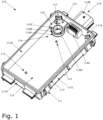
- Figure 1 shows a lower part 110 of an electronics enclosure 100.
- Electronics enclosure 100 has an upper part 130 shown in Figure 11 , having the form of a lid, which is configured to sealingly engage with lower part 110 to form the complete enclosure, as shown in Figure 12 .
- Lower part 110 in the configuration shown in Figure 1 has the form of a rectangular box having a generally planar lower wall 111, sidewalls 111A, 111B, 111C, and 111D which project vertically upwards from the plane of lower wall 111 so that an interior space 112 of enclosure 100 is partly enclosed on five sides.
- each of sidewalls 111 A, 111B, 111C, and 111D is recessed on an outer edge to provide a sealing rim over which the upper part 130 can sealingly engage.
- the upper part 130 has a corresponding projection formed on a lower surface thereof to be accommodated in recess 113, and may provide space for a seal, such as an o-ring seal or a bead of sealant, to be located between the lower part 110 and the upper part 130.
- the upper part 130 may, for example, be secured to lower part 110 by adhesive, or may be provided with fixtures such as locking clamps or screws to engage the upper part 130 to the lower part 110.
- the upper part 130 may be a generally flat structure as shown, or may itself partly enclosed interior space 112, for example by having a corresponding shape to the shape of the lower part 110 with an upper wall and sidewalls which continue, in the assembled state, from the sidewalls 111A, 111B, 111C and 111D of lower part 110.
- one of the sidewalls 111D is provided with connector assembly 114, which provides an internal terminal portion 114A a having conductors which extend through sidewall 111D to receptacle 114B.
- the conductors of terminal portion 114 a pass through sidewall 111D by means of appropriate sealing, for example by being in sealing contact with the material of sidewall 11D, or otherwise by passing through a seal block such as a rubber block which itself seals with sidewall 111D.
- a seal block such as a rubber block which itself seals with sidewall 111D.
- fixing points 115 which provide anchors for attaching, for example, an electronic component such as a printed circuit board (PCB).
- fixing points 115 extend from an interior surface of lower wall 111, but may also be provided at other locations such as on each of sidewalls 111A, 111B, 111C, 111D.
- fixing points 115 may be reinforced portions having a blind hole formed therein, into which a screw may be tapped. Arranging suitable holes in the electronic component over fixing points 115 and introducing a screw through the hole to the fixing point may be used to secure the electronic component.
- other means of securing electronic components within enclosure 100 may be provided by, for example, the use of adhesives, press-fit studs, retention clips or other fixtures.
- an aperture 117 is provided communicating between the interior space 112 and a relief chamber 118, which itself communicates with an exterior of the enclosure 100.
- aperture 117 is provided to a partition formed to extend from lower part 110 in the form of pedestal 116 which encloses the relief chamber 118.
- Relief chamber 118 communicates with the exterior of enclosure 100 through openings 119 and 120.
- Relief chamber 118 and openings 119 and 120 are not visible in Figure 1 , but are shown in the vertical cross-section of Figure 2 and the horizontal cross-section of Figure 3 .
- pedestal 116 has a wall portion 116 extending vertically from the plane of lower wall 111 and a roof portion 116B extending horizontally from wall portion 116A so as to enclose relief chamber 118.
- roof portion 116B is circular in periphery and wall portion 116 extends circumferentially around the periphery of roof portion 116B.
- roof portion may be, for example, domed, and/or wall portion 116 may be formed in a generally curved or in a polygonal shape, for example by a series of wall portions extending in a straight-line or curved configuration with angles defined therebetween. So, for example, pedestal 116 may, for example, be rectangular or hexagonal or octagonal in plan.
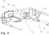
- tunnel structures 121 and 122 Extending between pedestal 116 and adjacent side walls 116B and 116D are tunnel structures 121 and 122. As shown in Figure 3 , tunnel structures 112 and 122 define tunnels 123 and 124 which extend from relief chamber 118 and which respectively terminate at openings 119 and 120.
- Figure 4 shows an alternative view of lower part 110 from an underside direction, in which lower surface 111 is visible, as well as openings 119 and 120 formed in respective sidewalls 111B and 111D.
- an overall passage for gas exists between space 112 and the exterior of the enclosure 100 through, sequentially, aperture 117, relief chamber 118, tunnels 123 and 124 and openings 119 and 120, whereby an overpressure or underpressure inside enclosure 100 may be relieved.
- membrane 116D is provided to cover aperture 117.
- Membrane 116D is gas-permeable but liquid-impermeable, and may be formed of a breathable material such as GORE TM membrane. Such breathable materials known in the art, and may be selected according to requirements.
- underside of membrane 116 is sealingly adhered by means of, for example, a peripheral adhesive bead to an upper surface of roof portion 116B so as to cover aperture 117.
- Membrane 116D thereby prevents ingress of moisture and/or dust between relief chamber 118 and space 112 through aperture 117.
- a recess 116C having the same size and shape as membrane 116D is formed on roof portion 116B to accommodate membrane 116, but in other configurations membrane 116 may be affixed to a sufficiently flat surface of roof portion 116B without any recess.
- recess 116C matches the peripheral shape of membrane 116D.
- the pro shape of membrane 116D or recess 116 there is no limitation on the pro shape of membrane 116D or recess 116, and either or both of these may be circular, rectangular, octagonal, hexagonal, or of irregular outline.
- a relief chamber 118 is arranged between interior space 112 and an exterior of enclosure 100, communicating by means of aperture 117 and at least one of openings 119 and 120, the opportunity for an incident jet of liquid to impinge directly on membrane 116D is reduced. Therefore, the forces experienced by membrane 116D resulting from, for example, a cleaning process using liquid jets may be reduced. As a result, the seal provided by membrane may be more durable and the enclosure is made more resistant against incoming moisture.
- a through-axis of aperture 117 which may be regarded as being a direction normal to a cross-section of aperture 117, is offset, both laterally and in angular direction, from each through-axis of openings 119 and 120.
- two openings 119, 120, with associated tunnels 123, 124 are provided which communicate with relief chamber 118.
- Providing two such openings from the exterior of enclosure 100 allows for liquid, which has entered through one opening, easily to drain through the other opening. Accordingly, a jet of liquid through one opening will not lead to a build-up of liquid in relief chamber 118 and hence an undesirable increase of inward pressure against membrane 116.
- the ability of the enclosure to resist incident liquid can further be improved.
- openings 119, 120 are arranged with through-axes which are angularly offset one to another.
- openings 119, 120 are located on different sidewalls, particularly adjacent sidewalls 111D, 111B.
- adjacent sidewalls 111D, 111B extend at an inclination one to the other, shown as a perpendicular inclination.
- Such a configuration promotes more effective drainage of liquid from relief chamber 118.
- providing the through-axes of openings 119, 120 to be perpendicular particularly efficiently promotes drainage, especially if the enclosure 100 may, in use, be installed at different orientations.
- tunnels 123, 124 which terminate at openings 119, 120, extend at an angle one to another, and in particular are arranged to extend linearly in directions perpendicular one to another.
- Such a configuration permits the enclosure 100 to be installed in a variety of orientations and to retain the ability effectively to drain liquid which has entered into relief chamber 118 out from relief chamber 118 by the force of gravity.
- tunnels 123 and 124 need not be at right angles to one another, and may be arranged at other angles.
- tunnels 123 and 124 are depicted as being formed in a straight line with a constant cross-section, in other configurations the cross-section can be narrowed or expanded along each tunnel. Further, the path of tunnels 123 and 124 may each be made curving or labyrinthine in order further to resist the incursion of liquid.
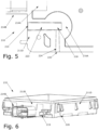
- the enclosure may have a lower part 220 having openings 219 and 220. Openings 219 and 220, which terminate tunnels 223 and 224, may have different cross-sections.
- the cross-section of tunnel 223 may be rectangular and may have constant dimensions, while the cross-section of tunnel 224 and associated opening 220 may be round and may taper, for example toward relief chamber 228.
- Other configurations of cross-section are possible, without limitation.
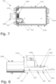
- lower part 320 is provided with one opening 319 arranged at one side wall 311D of enclosure 320 and connected to relief chamber 218 by tunnel 323.
- Lower part 320 is also provided with at least one second opening 320, here shown as a group of second openings 320, formed in lower surface 311 of lower part 320 and extending directly between lower surface 311 and relief chamber 328.
- aperture 317 formed in roof portion 316B of pedestal 316 may still be adequately protected from direct incidence of liquid jets since, for some applications, the enclosure may be mounted with openings 320 facing another surface, such as a surface to which lower panel 320 is fixed and by which it is supported. Moreover, aperture 317 may be protected from direct incidence of liquid jets by arranging the one or more openings 320 with through-axes offset from a through-axis of aperture 117. In the configuration of Figures 7 to 10 , openings 320 have through-axes which are laterally offset from a through-axis of aperture 317, for example.
- each opening as a group of smaller holes, by covering each opening with a grid with sufficiently small mesh spacing, in each case so as to disrupt or reduce the force of any incident liquid jet.
- example has been used of an essentially rectangular box-shaped enclosure, but the present configuration is also applicable to box-type enclosures having square, hexagonal, octagonal, or other polygonal outline.
- the present disclosure is applicable to enclosures which may have a circular outline, and which may have domed or otherwise non-planar upper and/or lower surfaces.
- the present disclosure can be equivalently applied in a drum-like enclosure having a planar lower surface and a dome-shaped upper surface, and wherein openings are provided either to locations in the circumferential wall of the drum or on at one location on the circumferential wall of the drum and on a planar lower surface of the drum.
- the present disclosure is also applicable to configurations in which only one exterior opening is provided, or whether at a side surface or a lower surface, or another surface of the enclosure.
- the above disclosure has been exemplified with respect to a two-part enclosure having a lower part and an upper part which sealingly engages with the lower portion as shown in Figure 12 .
- the enclosure can be configured, for example, to have two lateral half-portions which each comprise an upper wall, lower wall and one or more sidewalls, and which are joined together at an open end of each lateral half-portion.
- no terminal portion and corresponding perceptible receptacle may be provided for communicating electrical signals between interior and exterior of the enclosure, and communication may be provided, for example, by wireless means.
- each of the lower part of the enclosure and the upper part of the enclosure have each been shown as integral, unitary structures which may each be formed, for example, by injection moulding.
- the respective parts of each of these structures may also be formed separately and then sealably joined together by any suitable means such as adhesive or welding.
- the material of the enclosure is not limited, and may advantageously be manufactured from a plastic or ceramic material.
- a gas-permeable membrane may be sealingly adhered to an upper surface of a pedestal structure which defines a relief chamber; however, in other configurations a membrane may be also formed as an insert to a relief aperture or may be adhered to an inner surface of the relief chamber.
- the relief aperture has been exemplified by a circular through-hole, the relief aperture may be formed with a variety of cross-sections and shapes.
- an embodiment of the disclosure may be implemented as an electronics module having the enclosure and a radar sensor accommodated in a space inside the enclosure, for example on a PCB implementing a radar sensor.
- the sensor may be fixed inside the enclosure and communicating with elements outside of the enclosure by electronic signals transmitted via the terminal portion.
- the enclosure may be made of radar-transparent material.
Landscapes
- Engineering & Computer Science (AREA)
- Microelectronics & Electronic Packaging (AREA)
- Radar, Positioning & Navigation (AREA)
- Remote Sensing (AREA)
- Physics & Mathematics (AREA)
- Computer Networks & Wireless Communication (AREA)
- General Physics & Mathematics (AREA)
- Mechanical Engineering (AREA)
- Casings For Electric Apparatus (AREA)
- Electromagnetism (AREA)
Claims (13)
- Enceinte (100) pour système électronique, l'enceinte comprenant :une coque (130, 110) définissant un extérieur de l'enceinte et accueillant une chambre (112) principale à l'intérieur de la coque ;une cloison (116) définissant une chambre (118) de surpression s'étendant vers l'intérieur de la coque et présentant une ouverture (117) communiquant entre la chambre de surpression et la chambre principale ; etune membrane (116D) perméable aux gaz agencée de façon à recouvrir l'ouverture,caractérisée en ce quela coque présente des première et seconde ouvertures (119, 120) communiquant entre la chambre de surpression et l'extérieur de l'enceinte,les première et seconde ouvertures étant agencées sur des parois (111B, 111D) latérales adjacentes de l'enceinte et communiquant avec la chambre de surpression par des tunnels (123, 124) respectifs s'étendant avec un angle l'un par rapport à l'autre.
- Enceinte selon une quelconque revendication précédente, dans laquelle un axe traversant de chaque ouverture est décalé latéralement et/ou angulairement par rapport à un axe traversant de l'ouverture.
- Enceinte selon une quelconque revendication précédente, dans laquelle la cloison possède une portion (316A) formant paroi faisant saillie vers l'intérieur à partir de la coque et une portion (316B) formant toit s'étendant à partir de la portion formant paroi pour englober la chambre de surpression, la portion formant toit présentant l'ouverture.
- Enceinte selon une quelconque revendication précédente, comprenant en outre des première et seconde structures de tunnel fournissant les premier et second tunnels respectifs s'étendant entre les première et seconde ouvertures respectives et la chambre de surpression.
- Enceinte selon la revendication 4, dans laquelle chacun des premier et second tunnels s'étend en ligne droite.
- Enceinte selon la revendication 4 ou la revendication 5, dans laquelle chacun des premier et second tunnels s'étend dans une direction avec un angle par rapport à un axe traversant de l'ouverture.
- Enceinte selon la revendication 6, dans laquelle chacun des premier et second tunnels s'étend dans une direction perpendiculaire à un axe traversant de l'ouverture.
- Enceinte selon une quelconque revendication précédente, dans laquelle l'axe traversant de la seconde ouverture est perpendiculaire à un axe traversant de la première ouverture et perpendiculaire à un axe traversant de l'ouverture.
- Enceinte selon une quelconque revendication précédente, dans laquelle la membrane perméable aux gaz est agencée sur un côté chambre principale de la cloison.
- Enceinte selon une quelconque revendication précédente, dans laquelle la coque est en forme de boîte, la coque en forme de boîte présentant des parois (111, 130) supérieure et inférieure planes et des parois (111A, 111B, 111C, 111D) latérales planes s'étendant entre les parois supérieure et inférieure.
- Enceinte selon l'une quelconque des revendications 1 à 9,
dans laquelle la cloison s'étend vers l'intérieur à partir d'une paroi supérieure ou inférieure de la boîte, et dans laquelle l'ouverture est ménagée dans une paroi latérale de la boîte. - Enceinte selon une quelconque revendication précédente, dans laquelle l'enceinte satisfait les exigences IP6K6K selon la norme CEI 60529.
- Enceinte selon une quelconque revendication précédente, dans laquelle l'enceinte est une enceinte pour un système électronique de capteur radar monté sur véhicule.
Priority Applications (4)
| Application Number | Priority Date | Filing Date | Title |
|---|---|---|---|
| EP20198650.2A EP3975673B1 (fr) | 2020-09-28 | 2020-09-28 | Enceinte pour système électronique |
| US17/473,744 US11860295B2 (en) | 2020-09-28 | 2021-09-13 | Enclosure for electronics |
| CN202111127685.2A CN114325587B (zh) | 2020-09-28 | 2021-09-26 | 用于电子器件的外壳 |
| CN202122338590.7U CN216560973U (zh) | 2020-09-28 | 2021-09-26 | 用于电子器件的外壳 |
Applications Claiming Priority (1)
| Application Number | Priority Date | Filing Date | Title |
|---|---|---|---|
| EP20198650.2A EP3975673B1 (fr) | 2020-09-28 | 2020-09-28 | Enceinte pour système électronique |
Publications (2)
| Publication Number | Publication Date |
|---|---|
| EP3975673A1 EP3975673A1 (fr) | 2022-03-30 |
| EP3975673B1 true EP3975673B1 (fr) | 2024-04-10 |
Family
ID=72670489
Family Applications (1)
| Application Number | Title | Priority Date | Filing Date |
|---|---|---|---|
| EP20198650.2A Active EP3975673B1 (fr) | 2020-09-28 | 2020-09-28 | Enceinte pour système électronique |
Country Status (3)
| Country | Link |
|---|---|
| US (1) | US11860295B2 (fr) |
| EP (1) | EP3975673B1 (fr) |
| CN (2) | CN216560973U (fr) |
Families Citing this family (2)
| Publication number | Priority date | Publication date | Assignee | Title |
|---|---|---|---|---|
| EP3923428B1 (fr) * | 2020-06-10 | 2022-12-14 | ABB Schweiz AG | Agencement de décompression |
| EP3975673B1 (fr) * | 2020-09-28 | 2024-04-10 | Aptiv Technologies Limited | Enceinte pour système électronique |
Family Cites Families (9)
| Publication number | Priority date | Publication date | Assignee | Title |
|---|---|---|---|---|
| DE19544974C1 (de) * | 1995-12-01 | 1997-05-22 | Siemens Ag | Steuergerät, insbesondere zur Auslösung eines Rückhaltemittels in einem Fahrzeug |
| US6854324B2 (en) * | 2002-12-20 | 2005-02-15 | The Goodyear Tire & Rubber Company | Tire monitoring apparatus |
| DE102006053114A1 (de) * | 2006-11-10 | 2008-05-15 | Robert Bosch Gmbh | Druckausgleich für ein Gehäuse |
| JP6105887B2 (ja) * | 2012-09-28 | 2017-03-29 | 日立オートモティブシステムズ株式会社 | 電子制御装置 |
| DE102014209874A1 (de) * | 2014-05-23 | 2015-11-26 | Conti Temic Microelectronic Gmbh | Steuergerät für ein Fahrzeug mit einem einen Drucksensor aufweisenden Gehäuse |
| US9769951B2 (en) * | 2015-07-08 | 2017-09-19 | Autoliv Asp, Inc. | Automotive radar system and automotive radar sensor module with breather structure |
| EP3250014B1 (fr) * | 2016-05-24 | 2019-12-18 | Veoneer Sweden AB | Boîtier pour composants électroniques |
| EP3468319B1 (fr) * | 2017-10-04 | 2021-08-18 | Veoneer Sweden AB | Unité de commande électrique |
| EP3975673B1 (fr) * | 2020-09-28 | 2024-04-10 | Aptiv Technologies Limited | Enceinte pour système électronique |
-
2020
- 2020-09-28 EP EP20198650.2A patent/EP3975673B1/fr active Active
-
2021
- 2021-09-13 US US17/473,744 patent/US11860295B2/en active Active
- 2021-09-26 CN CN202122338590.7U patent/CN216560973U/zh active Active
- 2021-09-26 CN CN202111127685.2A patent/CN114325587B/zh active Active
Also Published As
| Publication number | Publication date |
|---|---|
| US11860295B2 (en) | 2024-01-02 |
| CN114325587B (zh) | 2024-12-13 |
| EP3975673A1 (fr) | 2022-03-30 |
| US20220099792A1 (en) | 2022-03-31 |
| CN216560973U (zh) | 2022-05-17 |
| CN114325587A (zh) | 2022-04-12 |
Similar Documents
| Publication | Publication Date | Title |
|---|---|---|
| US5392197A (en) | Moisture proof of electric device for motor vehicles | |
| EP3468319B1 (fr) | Unité de commande électrique | |
| US11860295B2 (en) | Enclosure for electronics | |
| CN105791642B (zh) | 摄像头模块和用于车辆的摄像头 | |
| US20150303669A1 (en) | Electronic component unit and wire harness | |
| JP2013069735A (ja) | 電子制御装置のシール構造 | |
| EP2914073B1 (fr) | Unité électronique | |
| EP3584121B1 (fr) | Boîtier, boîte de connexion électrique et faisceau de câbles | |
| US9391437B2 (en) | Electrical junction box | |
| JP2013069736A (ja) | 電子制御装置 | |
| CN105658000A (zh) | 压力补正装置及包括其的电子控制装置模块 | |
| JP2014209639A (ja) | 電子制御装置 | |
| JP2018082090A (ja) | 電子装置 | |
| US10483729B1 (en) | Vented power distribution housing | |
| JP4966647B2 (ja) | 電気接続箱のシール構造 | |
| CN119895640A (zh) | 能够进行无线通信的电芯监测电路及设置有其的电池模块 | |
| US12069814B2 (en) | Electronic unit | |
| CN103457115A (zh) | 用于安装在防爆外壳内的电连接器插座以及安装方法 | |
| KR20230090597A (ko) | 배터리용 커넥터 | |
| CN210298241U (zh) | 控制盒密封结构、控制盒及共享车辆 | |
| JP6733404B2 (ja) | 回路基板ユニットの防水固定装置 | |
| JP2008208648A (ja) | 筐体の浸水検知構造 | |
| US7683258B2 (en) | Wire harness that prevents water ingress | |
| US12127359B2 (en) | Electronic unit | |
| KR101927120B1 (ko) | 내부 격벽을 구비한 전자 제어 장치 |
Legal Events
| Date | Code | Title | Description |
|---|---|---|---|
| PUAI | Public reference made under article 153(3) epc to a published international application that has entered the european phase |
Free format text: ORIGINAL CODE: 0009012 |
|
| STAA | Information on the status of an ep patent application or granted ep patent |
Free format text: STATUS: THE APPLICATION HAS BEEN PUBLISHED |
|
| AK | Designated contracting states |
Kind code of ref document: A1 Designated state(s): AL AT BE BG CH CY CZ DE DK EE ES FI FR GB GR HR HU IE IS IT LI LT LU LV MC MK MT NL NO PL PT RO RS SE SI SK SM TR |
|
| STAA | Information on the status of an ep patent application or granted ep patent |
Free format text: STATUS: REQUEST FOR EXAMINATION WAS MADE |
|
| 17P | Request for examination filed |
Effective date: 20220920 |
|
| RBV | Designated contracting states (corrected) |
Designated state(s): AL AT BE BG CH CY CZ DE DK EE ES FI FR GB GR HR HU IE IS IT LI LT LU LV MC MK MT NL NO PL PT RO RS SE SI SK SM TR |
|
| RAP3 | Party data changed (applicant data changed or rights of an application transferred) |
Owner name: APTIV TECHNOLOGIES LIMITED |
|
| GRAP | Despatch of communication of intention to grant a patent |
Free format text: ORIGINAL CODE: EPIDOSNIGR1 |
|
| STAA | Information on the status of an ep patent application or granted ep patent |
Free format text: STATUS: GRANT OF PATENT IS INTENDED |
|
| INTG | Intention to grant announced |
Effective date: 20231116 |
|
| GRAS | Grant fee paid |
Free format text: ORIGINAL CODE: EPIDOSNIGR3 |
|
| GRAA | (expected) grant |
Free format text: ORIGINAL CODE: 0009210 |
|
| STAA | Information on the status of an ep patent application or granted ep patent |
Free format text: STATUS: THE PATENT HAS BEEN GRANTED |
|
| AK | Designated contracting states |
Kind code of ref document: B1 Designated state(s): AL AT BE BG CH CY CZ DE DK EE ES FI FR GB GR HR HU IE IS IT LI LT LU LV MC MK MT NL NO PL PT RO RS SE SI SK SM TR |
|
| REG | Reference to a national code |
Ref country code: GB Ref legal event code: FG4D |
|
| REG | Reference to a national code |
Ref country code: CH Ref legal event code: EP |
|
| P01 | Opt-out of the competence of the unified patent court (upc) registered |
Effective date: 20240313 |
|
| REG | Reference to a national code |
Ref country code: DE Ref legal event code: R096 Ref document number: 602020028646 Country of ref document: DE |
|
| REG | Reference to a national code |
Ref country code: IE Ref legal event code: FG4D |
|
| RAP2 | Party data changed (patent owner data changed or rights of a patent transferred) |
Owner name: APTIV TECHNOLOGIES AG |
|
| REG | Reference to a national code |
Ref country code: LT Ref legal event code: MG9D |
|
| REG | Reference to a national code |
Ref country code: NL Ref legal event code: MP Effective date: 20240410 |
|
| REG | Reference to a national code |
Ref country code: AT Ref legal event code: MK05 Ref document number: 1676222 Country of ref document: AT Kind code of ref document: T Effective date: 20240410 |
|
| PG25 | Lapsed in a contracting state [announced via postgrant information from national office to epo] |
Ref country code: NL Free format text: LAPSE BECAUSE OF FAILURE TO SUBMIT A TRANSLATION OF THE DESCRIPTION OR TO PAY THE FEE WITHIN THE PRESCRIBED TIME-LIMIT Effective date: 20240410 |
|
| RAP4 | Party data changed (patent owner data changed or rights of a patent transferred) |
Owner name: APTIV TECHNOLOGIES AG |
|
| PG25 | Lapsed in a contracting state [announced via postgrant information from national office to epo] |
Ref country code: NL Free format text: LAPSE BECAUSE OF FAILURE TO SUBMIT A TRANSLATION OF THE DESCRIPTION OR TO PAY THE FEE WITHIN THE PRESCRIBED TIME-LIMIT Effective date: 20240410 |
|
| PG25 | Lapsed in a contracting state [announced via postgrant information from national office to epo] |
Ref country code: IS Free format text: LAPSE BECAUSE OF FAILURE TO SUBMIT A TRANSLATION OF THE DESCRIPTION OR TO PAY THE FEE WITHIN THE PRESCRIBED TIME-LIMIT Effective date: 20240810 |
|
| PG25 | Lapsed in a contracting state [announced via postgrant information from national office to epo] |
Ref country code: BG Free format text: LAPSE BECAUSE OF FAILURE TO SUBMIT A TRANSLATION OF THE DESCRIPTION OR TO PAY THE FEE WITHIN THE PRESCRIBED TIME-LIMIT Effective date: 20240410 |
|
| PG25 | Lapsed in a contracting state [announced via postgrant information from national office to epo] |
Ref country code: HR Free format text: LAPSE BECAUSE OF FAILURE TO SUBMIT A TRANSLATION OF THE DESCRIPTION OR TO PAY THE FEE WITHIN THE PRESCRIBED TIME-LIMIT Effective date: 20240410 Ref country code: FI Free format text: LAPSE BECAUSE OF FAILURE TO SUBMIT A TRANSLATION OF THE DESCRIPTION OR TO PAY THE FEE WITHIN THE PRESCRIBED TIME-LIMIT Effective date: 20240410 |
|
| PG25 | Lapsed in a contracting state [announced via postgrant information from national office to epo] |
Ref country code: GR Free format text: LAPSE BECAUSE OF FAILURE TO SUBMIT A TRANSLATION OF THE DESCRIPTION OR TO PAY THE FEE WITHIN THE PRESCRIBED TIME-LIMIT Effective date: 20240711 |
|
| PG25 | Lapsed in a contracting state [announced via postgrant information from national office to epo] |
Ref country code: PT Free format text: LAPSE BECAUSE OF FAILURE TO SUBMIT A TRANSLATION OF THE DESCRIPTION OR TO PAY THE FEE WITHIN THE PRESCRIBED TIME-LIMIT Effective date: 20240812 |
|
| PG25 | Lapsed in a contracting state [announced via postgrant information from national office to epo] |
Ref country code: ES Free format text: LAPSE BECAUSE OF FAILURE TO SUBMIT A TRANSLATION OF THE DESCRIPTION OR TO PAY THE FEE WITHIN THE PRESCRIBED TIME-LIMIT Effective date: 20240410 |
|
| PG25 | Lapsed in a contracting state [announced via postgrant information from national office to epo] |
Ref country code: AT Free format text: LAPSE BECAUSE OF FAILURE TO SUBMIT A TRANSLATION OF THE DESCRIPTION OR TO PAY THE FEE WITHIN THE PRESCRIBED TIME-LIMIT Effective date: 20240410 |
|
| PG25 | Lapsed in a contracting state [announced via postgrant information from national office to epo] |
Ref country code: PL Free format text: LAPSE BECAUSE OF FAILURE TO SUBMIT A TRANSLATION OF THE DESCRIPTION OR TO PAY THE FEE WITHIN THE PRESCRIBED TIME-LIMIT Effective date: 20240410 |
|
| PG25 | Lapsed in a contracting state [announced via postgrant information from national office to epo] |
Ref country code: LV Free format text: LAPSE BECAUSE OF FAILURE TO SUBMIT A TRANSLATION OF THE DESCRIPTION OR TO PAY THE FEE WITHIN THE PRESCRIBED TIME-LIMIT Effective date: 20240410 |
|
| PG25 | Lapsed in a contracting state [announced via postgrant information from national office to epo] |
Ref country code: PT Free format text: LAPSE BECAUSE OF FAILURE TO SUBMIT A TRANSLATION OF THE DESCRIPTION OR TO PAY THE FEE WITHIN THE PRESCRIBED TIME-LIMIT Effective date: 20240812 Ref country code: PL Free format text: LAPSE BECAUSE OF FAILURE TO SUBMIT A TRANSLATION OF THE DESCRIPTION OR TO PAY THE FEE WITHIN THE PRESCRIBED TIME-LIMIT Effective date: 20240410 Ref country code: NO Free format text: LAPSE BECAUSE OF FAILURE TO SUBMIT A TRANSLATION OF THE DESCRIPTION OR TO PAY THE FEE WITHIN THE PRESCRIBED TIME-LIMIT Effective date: 20240710 Ref country code: LV Free format text: LAPSE BECAUSE OF FAILURE TO SUBMIT A TRANSLATION OF THE DESCRIPTION OR TO PAY THE FEE WITHIN THE PRESCRIBED TIME-LIMIT Effective date: 20240410 Ref country code: IS Free format text: LAPSE BECAUSE OF FAILURE TO SUBMIT A TRANSLATION OF THE DESCRIPTION OR TO PAY THE FEE WITHIN THE PRESCRIBED TIME-LIMIT Effective date: 20240810 Ref country code: HR Free format text: LAPSE BECAUSE OF FAILURE TO SUBMIT A TRANSLATION OF THE DESCRIPTION OR TO PAY THE FEE WITHIN THE PRESCRIBED TIME-LIMIT Effective date: 20240410 Ref country code: GR Free format text: LAPSE BECAUSE OF FAILURE TO SUBMIT A TRANSLATION OF THE DESCRIPTION OR TO PAY THE FEE WITHIN THE PRESCRIBED TIME-LIMIT Effective date: 20240711 Ref country code: FI Free format text: LAPSE BECAUSE OF FAILURE TO SUBMIT A TRANSLATION OF THE DESCRIPTION OR TO PAY THE FEE WITHIN THE PRESCRIBED TIME-LIMIT Effective date: 20240410 Ref country code: ES Free format text: LAPSE BECAUSE OF FAILURE TO SUBMIT A TRANSLATION OF THE DESCRIPTION OR TO PAY THE FEE WITHIN THE PRESCRIBED TIME-LIMIT Effective date: 20240410 Ref country code: BG Free format text: LAPSE BECAUSE OF FAILURE TO SUBMIT A TRANSLATION OF THE DESCRIPTION OR TO PAY THE FEE WITHIN THE PRESCRIBED TIME-LIMIT Effective date: 20240410 Ref country code: AT Free format text: LAPSE BECAUSE OF FAILURE TO SUBMIT A TRANSLATION OF THE DESCRIPTION OR TO PAY THE FEE WITHIN THE PRESCRIBED TIME-LIMIT Effective date: 20240410 Ref country code: RS Free format text: LAPSE BECAUSE OF FAILURE TO SUBMIT A TRANSLATION OF THE DESCRIPTION OR TO PAY THE FEE WITHIN THE PRESCRIBED TIME-LIMIT Effective date: 20240710 |
|
| REG | Reference to a national code |
Ref country code: DE Ref legal event code: R097 Ref document number: 602020028646 Country of ref document: DE |
|
| PG25 | Lapsed in a contracting state [announced via postgrant information from national office to epo] |
Ref country code: DK Free format text: LAPSE BECAUSE OF FAILURE TO SUBMIT A TRANSLATION OF THE DESCRIPTION OR TO PAY THE FEE WITHIN THE PRESCRIBED TIME-LIMIT Effective date: 20240410 |
|
| PG25 | Lapsed in a contracting state [announced via postgrant information from national office to epo] |
Ref country code: EE Free format text: LAPSE BECAUSE OF FAILURE TO SUBMIT A TRANSLATION OF THE DESCRIPTION OR TO PAY THE FEE WITHIN THE PRESCRIBED TIME-LIMIT Effective date: 20240410 |
|
| PG25 | Lapsed in a contracting state [announced via postgrant information from national office to epo] |
Ref country code: CZ Free format text: LAPSE BECAUSE OF FAILURE TO SUBMIT A TRANSLATION OF THE DESCRIPTION OR TO PAY THE FEE WITHIN THE PRESCRIBED TIME-LIMIT Effective date: 20240410 |
|
| PG25 | Lapsed in a contracting state [announced via postgrant information from national office to epo] |
Ref country code: RO Free format text: LAPSE BECAUSE OF FAILURE TO SUBMIT A TRANSLATION OF THE DESCRIPTION OR TO PAY THE FEE WITHIN THE PRESCRIBED TIME-LIMIT Effective date: 20240410 Ref country code: SK Free format text: LAPSE BECAUSE OF FAILURE TO SUBMIT A TRANSLATION OF THE DESCRIPTION OR TO PAY THE FEE WITHIN THE PRESCRIBED TIME-LIMIT Effective date: 20240410 |
|
| PG25 | Lapsed in a contracting state [announced via postgrant information from national office to epo] |
Ref country code: SM Free format text: LAPSE BECAUSE OF FAILURE TO SUBMIT A TRANSLATION OF THE DESCRIPTION OR TO PAY THE FEE WITHIN THE PRESCRIBED TIME-LIMIT Effective date: 20240410 |
|
| PG25 | Lapsed in a contracting state [announced via postgrant information from national office to epo] |
Ref country code: SM Free format text: LAPSE BECAUSE OF FAILURE TO SUBMIT A TRANSLATION OF THE DESCRIPTION OR TO PAY THE FEE WITHIN THE PRESCRIBED TIME-LIMIT Effective date: 20240410 Ref country code: SK Free format text: LAPSE BECAUSE OF FAILURE TO SUBMIT A TRANSLATION OF THE DESCRIPTION OR TO PAY THE FEE WITHIN THE PRESCRIBED TIME-LIMIT Effective date: 20240410 Ref country code: RO Free format text: LAPSE BECAUSE OF FAILURE TO SUBMIT A TRANSLATION OF THE DESCRIPTION OR TO PAY THE FEE WITHIN THE PRESCRIBED TIME-LIMIT Effective date: 20240410 Ref country code: EE Free format text: LAPSE BECAUSE OF FAILURE TO SUBMIT A TRANSLATION OF THE DESCRIPTION OR TO PAY THE FEE WITHIN THE PRESCRIBED TIME-LIMIT Effective date: 20240410 Ref country code: DK Free format text: LAPSE BECAUSE OF FAILURE TO SUBMIT A TRANSLATION OF THE DESCRIPTION OR TO PAY THE FEE WITHIN THE PRESCRIBED TIME-LIMIT Effective date: 20240410 Ref country code: CZ Free format text: LAPSE BECAUSE OF FAILURE TO SUBMIT A TRANSLATION OF THE DESCRIPTION OR TO PAY THE FEE WITHIN THE PRESCRIBED TIME-LIMIT Effective date: 20240410 |
|
| PG25 | Lapsed in a contracting state [announced via postgrant information from national office to epo] |
Ref country code: IT Free format text: LAPSE BECAUSE OF FAILURE TO SUBMIT A TRANSLATION OF THE DESCRIPTION OR TO PAY THE FEE WITHIN THE PRESCRIBED TIME-LIMIT Effective date: 20240410 |
|
| PLBE | No opposition filed within time limit |
Free format text: ORIGINAL CODE: 0009261 |
|
| STAA | Information on the status of an ep patent application or granted ep patent |
Free format text: STATUS: NO OPPOSITION FILED WITHIN TIME LIMIT |
|
| 26N | No opposition filed |
Effective date: 20250113 |
|
| PG25 | Lapsed in a contracting state [announced via postgrant information from national office to epo] |
Ref country code: MC Free format text: LAPSE BECAUSE OF FAILURE TO SUBMIT A TRANSLATION OF THE DESCRIPTION OR TO PAY THE FEE WITHIN THE PRESCRIBED TIME-LIMIT Effective date: 20240410 Ref country code: SI Free format text: LAPSE BECAUSE OF FAILURE TO SUBMIT A TRANSLATION OF THE DESCRIPTION OR TO PAY THE FEE WITHIN THE PRESCRIBED TIME-LIMIT Effective date: 20240410 |
|
| REG | Reference to a national code |
Ref country code: CH Ref legal event code: PL |
|
| PG25 | Lapsed in a contracting state [announced via postgrant information from national office to epo] |
Ref country code: LU Free format text: LAPSE BECAUSE OF NON-PAYMENT OF DUE FEES Effective date: 20240928 |
|
| REG | Reference to a national code |
Ref country code: BE Ref legal event code: MM Effective date: 20240930 |
|
| PG25 | Lapsed in a contracting state [announced via postgrant information from national office to epo] |
Ref country code: BE Free format text: LAPSE BECAUSE OF NON-PAYMENT OF DUE FEES Effective date: 20240930 |
|
| PG25 | Lapsed in a contracting state [announced via postgrant information from national office to epo] |
Ref country code: CH Free format text: LAPSE BECAUSE OF NON-PAYMENT OF DUE FEES Effective date: 20240930 |
|
| PG25 | Lapsed in a contracting state [announced via postgrant information from national office to epo] |
Ref country code: IE Free format text: LAPSE BECAUSE OF NON-PAYMENT OF DUE FEES Effective date: 20240928 |
|
| PG25 | Lapsed in a contracting state [announced via postgrant information from national office to epo] |
Ref country code: SE Free format text: LAPSE BECAUSE OF FAILURE TO SUBMIT A TRANSLATION OF THE DESCRIPTION OR TO PAY THE FEE WITHIN THE PRESCRIBED TIME-LIMIT Effective date: 20240410 |
|
| PGFP | Annual fee paid to national office [announced via postgrant information from national office to epo] |
Ref country code: DE Payment date: 20250814 Year of fee payment: 6 |
|
| PGFP | Annual fee paid to national office [announced via postgrant information from national office to epo] |
Ref country code: GB Payment date: 20250924 Year of fee payment: 6 |
|
| PGFP | Annual fee paid to national office [announced via postgrant information from national office to epo] |
Ref country code: FR Payment date: 20250908 Year of fee payment: 6 |
|
| PG25 | Lapsed in a contracting state [announced via postgrant information from national office to epo] |
Ref country code: CY Free format text: LAPSE BECAUSE OF FAILURE TO SUBMIT A TRANSLATION OF THE DESCRIPTION OR TO PAY THE FEE WITHIN THE PRESCRIBED TIME-LIMIT; INVALID AB INITIO Effective date: 20200928 |
|
| PG25 | Lapsed in a contracting state [announced via postgrant information from national office to epo] |
Ref country code: HU Free format text: LAPSE BECAUSE OF FAILURE TO SUBMIT A TRANSLATION OF THE DESCRIPTION OR TO PAY THE FEE WITHIN THE PRESCRIBED TIME-LIMIT; INVALID AB INITIO Effective date: 20200928 |