EP3974892A1 - Computerimplementiertes verfahren zur bestimmung einer numerischen darstellung eines brillenglases - Google Patents
Computerimplementiertes verfahren zur bestimmung einer numerischen darstellung eines brillenglases Download PDFInfo
- Publication number
- EP3974892A1 EP3974892A1 EP20198266.7A EP20198266A EP3974892A1 EP 3974892 A1 EP3974892 A1 EP 3974892A1 EP 20198266 A EP20198266 A EP 20198266A EP 3974892 A1 EP3974892 A1 EP 3974892A1
- Authority
- EP
- European Patent Office
- Prior art keywords
- spectacle lens
- apex
- rays
- eye
- points
- Prior art date
- Legal status (The legal status is an assumption and is not a legal conclusion. Google has not performed a legal analysis and makes no representation as to the accuracy of the status listed.)
- Withdrawn
Links
Images


Classifications
-
- G—PHYSICS
- G02—OPTICS
- G02C—SPECTACLES; SUNGLASSES OR GOGGLES INSOFAR AS THEY HAVE THE SAME FEATURES AS SPECTACLES; CONTACT LENSES
- G02C7/00—Optical parts
- G02C7/02—Lenses; Lens systems ; Methods of designing lenses
- G02C7/024—Methods of designing ophthalmic lenses
- G02C7/025—Methods of designing ophthalmic lenses considering parameters of the viewed object
-
- G—PHYSICS
- G02—OPTICS
- G02C—SPECTACLES; SUNGLASSES OR GOGGLES INSOFAR AS THEY HAVE THE SAME FEATURES AS SPECTACLES; CONTACT LENSES
- G02C7/00—Optical parts
- G02C7/02—Lenses; Lens systems ; Methods of designing lenses
- G02C7/024—Methods of designing ophthalmic lenses
- G02C7/027—Methods of designing ophthalmic lenses considering wearer's parameters
-
- G—PHYSICS
- G02—OPTICS
- G02C—SPECTACLES; SUNGLASSES OR GOGGLES INSOFAR AS THEY HAVE THE SAME FEATURES AS SPECTACLES; CONTACT LENSES
- G02C7/00—Optical parts
- G02C7/02—Lenses; Lens systems ; Methods of designing lenses
- G02C7/024—Methods of designing ophthalmic lenses
- G02C7/028—Special mathematical design techniques
Definitions
- the present invention relates to a computer implemented method of determining a numerical representation of a spectacle lens as well as to a data processing system for determining a numerical representation of a spectacle lens, a computer program for determining a numerical representation of a spectacle lens, and a non-volatile computer readable storage medium.
- the invention relates to a method of manufacturing a spectacle lens.
- spectacle lenses are individualized optical devices designed for providing clear view in different viewing directions which means that a desired power of the spectacle lens needs to be achieved for pencils of rays passing the spectacle lens in different directions.
- spectacle lenses may be multifocal lenses such as, for example, bifocal lenses, trifocal lenses or progressive addition lenses (PALs), which means that different prescription powers need to be achieved in different viewing directions.
- an individualized spectacle lens is typically produced by use of CNC-process based on a numerical representation of the individualized spectacle lens.
- a numerical representation of a spectacle lens is determined by a numerical optimization process in which at least one surface of a numerically represented working spectacle lens is optimized such that a prescribed power is achieved for a number of viewing directions and, at the same time, a distribution of properties of the spectacle lens corresponding to a distribution defined by a target design is reached.
- the distribution of properties may, for example, be a distribution of a residual error of spherical power or a distribution of a residual error of astigmatic power in different viewing directions. This residual error represents a deviation of the respective power realized with the optimized spectacle lens from the desired power when viewing through the spectacle lens in its as-worn position.
- the distribution of properties may represent a surface power or a surface astigmatism of the optimized spectacle lens surface.
- Methods of optimizing spectacle lenses are descripted in US 6,382,789 B1 , EP 1 744 203 A1 , EP 0 857 993 A2 , DE 10 2017 178 721 A1 and DE 10 2017 118 219 A1 , for example.
- a numerical optimization is done for a number of pencils of rays each passing along the visual axis that extends from a fixation point through the spectacle lens, the pupil and the pivot point of the eye, where each pencil of rays extends along different viewing direction.
- each point on the sphere represents a different viewing direction.
- the sphere has a radius that corresponds to the distance between the pivot point of the eye and the rear surface of the spectacle lens along the viewing direction of the eye with the eye in primary position.
- This objective is achieved by a computer implemented method of determining a numerical representation of a spectacle lens as claimed in claim 1, by a computer program for determining a numerical representation of a spectacle lens as claimed in claim 10, by a non-volatile computer readable storage medium with program code comprising instructions for determining a numerical representation of a spectacle lens as claimed in claim 11, by a data processing system for determining a numerical representation of a spectacle lens as claimed in claim 12, and by a non-volatile computer readable storage medium with a numerical representation of a spectacle lens as claimed in claim 13.
- the second objective is achieved by a single vision spectacle lens as claimed in claim 14, and the third objective by a method of manufacturing a spectacle lens as claimed in claim 15.
- back focal length is used to indicate a distance between a ray passing point on a surface and a focal point or a focal line along a principal ray.
- back focal length is used to indicate a distance between a ray passing point of the vertex surface and a focal point or line along a principal ray.
- power refers to the capacity of a lens or optical surface to change the curvature or direction of incident wave fronts by refraction (see DIN EN ISO 13666:2019, section 3.1.10).
- dioptric power is a general term encompassing the "focal power” and the “prismatic power” (see DIN EN ISO 13666:2019, section 3.10.3), where the term “focal power” encompasses the "spherical vertex power” and the "astigmatic vertex power” of a spectacle lens (DIN EN ISO 13666:2019, section 3.10.2).
- all vertex powers are back vertex powers which are given by the reciprocal of the paraxial back focal length measured in meters.
- progressive-addition lens refers to a spectacle lens with variable power and two reference points for focal power, usually designed for providing a correction for presbyopia and clear vision from distance vision to near vision (see DIN ISO 13666:2019, section 3.7.8).
- a progressive-addition lens includes a near vision zone and a distance vision zone where the terms "near vision zone” and “distance vision zone” refer to that portion of the progressive-addition lens having the power for near vision and that portion of a progressive-addition lens having the power for distance vision, respectively.
- the difference between the near power and the distance power experienced by the wearer is called addition power.
- progression zone between the near vision zone and the distance vision zone in which the power experienced by the wearer progresses continuously from the power for distance vision to the power for near vision and in which the vision for the wearer is clear.
- the length of the progression zone is called progression length.
- distance design reference point refers to that point stipulated by the manufacturer, on the front surface of a finished spectacle lens or on the finished surface of a lens blank, at which the design specification for the distance vision zone apply (see DIN EN ISO 13666:2019, section 3.2.17).
- near design reference point refers to that point stipulated by the manufacturer, on the front surface of a finished spectacle lens or on the finished surface of a lens blank, at which the design specification for the near vision zone apply (see DIN EN ISO 13666:2019, section 3.2.18).
- lens blank referes to a piece of optical material with one optically finished surface for the making of a lens (see DIN EN ISO 13666:2019, section 3.8.1)
- prescription data or "individual prescription data” is used as generic term for a set of optical characteristics of the spectacle lens, such as, e.g., dioptric power, addition power, refractive index, and progression length, according to a prescription.
- freeform surface refers to a surface which may freely be formed during the manufacturing process and which does not need to show axial symmetry or rotational symmetry.
- a freeform surface may lead to different powers in different sections of the surface.
- the use of freeform surfaces allows for improving the quality of spectacle lenses with regard to imaging quality experienced by the wearer, as the spectacle lens can be optimized with respect to individual prescription values of the wearer, as well as to individual centration and frame data.
- Freeform surfaces of progressive power lenses include a larger number of parameters, which may be taken into account in the calculation of the surface than in the calculation of the freeform surfaces for single vision lenses, e.g. the progression length or the addition power.
- target design describes a specification of the properties of a spectacle lens and/or of a surface of the spectacle lens.
- the properties may in particular but not exclusively include the distribution of power of the spectacle lens, distributions of optical aberrations in the beam path running through a spectacle lens, through the pupil and through the eye's center of rotation, and/or distributions of surface properties over a surface of the spectacle lens and/or targets and limits for the refractive index distribution and/or targets and limits for the derivatives of the refractive index distribution of the lens material.
- visual axis (British English) or “line of sight” (US English) refers to a beam path from a fixation point in object space to the center of the entrance pupil of the eye and its continuation in image space from the center of the entrance pupil to the fixation space on the retina, which is typically the fovea centralis (see DIN EN ISO 13666:2019, section 3.2.24).
- primary direction refers to the direction of the visual axis, usually taken to be the horizontal, to an object at an infinite distance measured with habitual head and body posture when looking straight ahead in unaided vision (see DIN EN ISO 13666:2019, section 3.2.25)
- primary position refers to the position of the eye when viewing in primary direction (see DIN EN ISO 13666:2019, section 3.2.26).
- as-worn position refers to a position and orientation of the spectacle lens relative to the eyes and face during wear (see DIN EN ISO 13666:2019, section 3.2.36) and includes at least values for the vertex distance, the face form angle and the as-worn pantoscopic angle.
- vertex distance refers to the horizontal distance between the rear surface of the spectacle lens and the apex of the cornea as measured with the eye in primary position (see DIN EN ISO 13666:2019, section 3.2.40).
- the "face form angle” is an angle between the plane of the spectacle front and the right plane of the lens shape or of the left plane of the lens shape, where the plane of the spectacle front is a plane that contains the vertical centerlines of the right and left boxed lens shapes, the plane of the lens shape is a plane that contains the vertical centerline and is parallel to the horizontal centerline of the individual lens, and where the lens shape is the outline of the edged lens periphery in its intended orientation (see DIN EN ISO 13666:2019, section 3.2.39).
- the "as-worn pantoscopic angle” refers to a vertical angle formed between the horizontal and a line perpendicular to a reference line that runs through the base of the notch in the upper and lower rim of the frame and lies in a vertical plane including the primary direction (see DIN EN ISO 13666:2019, section 3.2.37).
- pencil of rays is used to indicate a geometric construct used to describe a beam or portion of a light beam as a narrow cone or cylinder formed by a number of rays.
- the diameter of the pencil of rays is defined by the pupil diameter, which affects the optical power calculation of the pencil of rays.
- principal ray is used in the context of a pencil of rays to indicate a ray of the pencil of rays that forms in any section through the pencil of rays that is perpendicular to said ray the geometrical center of said section.
- ray tracing is used to indicate a method of calculating the paths of rays of a pencil of rays taking into account refractive and/or reflective surfaces encountered by the pencil of rays.
- number of a spectacle lens is used to indicate a computer readable data set representing a spectacle lens.
- working spectacle lens is used to indicate a spectacle lens given in form of a numerical representation with at least one parameterized surface that is to be optimized in an optimization process and/or at least one refractive index distribution of the lens material that is to be optimized in an optimization process.
- ray passing point is used to indicate a point of a surface which is passed by a ray of a pencil of rays.
- apex surface is used to indicate a surface on which the apex of the cornea moves when the eye rotates.
- vertex surface is used to indicate a surface that is constructed by adding to each point of an apex surface the vertex distance in a defined direction with respect to the surface normal of the apex surface. Based on this vertex surface the back focal length for the wearer can be calculated for each viewing direction of the eye respectively for each ray path of the principal ray by the distance of the ray passing point through the vertex surface to the focal point or focal line of the pencil of rays along the principal ray.
- toroidal is used in the context of a surface to indicate a surface that is a section of the surface of a torus.
- azimuth angle is used throughout the specification to indicate an angle between a radial line in a plane perpendicular to the normal vector of a surface and a fixed radial reference line within said plain.
- orientation of the fixed radial line relative to the normal vector shall be constant, i.e. when the orientation of the normal vector at the apex of the cornea changes in three-dimensional space due to a change in the viewing direction the orientation of the fixed radial line changes in the same manner, where a rotation of the fixed radial line about the normal vector only takes place by the amount in which the eye rotates about the normal vector at the apex of the cornea when the viewing direction is changed.
- polar angle is used throughout the specification to indicate an angle between a direction and the normal direction.
- a numerically represented working spectacle lens is optimized by means of ray tracing using a number of pencils of rays along different viewing directions in order to obtain an optimized working spectacle lens.
- at least one lens surface of the working spectacle lens may be optimized.
- the distribution of the refractive index of the working spectacle lens may be optimized.
- the optimized working spectacle lens then constitutes the numerical representation of the spectacle lens to be determined.
- the number of the pencils of rays used for the ray tracing is at least two and typically considerably higher than two, for example a two-digit or three-digit number.
- the principal rays of the pencils of rays each pass different ray passing points which form points of a vertex surface.
- Each principal ray extends along a viewing direction related to the respective ray passing point.
- the three-dimensional locations of the ray passing points are determined by surface points of a non-spherical apex surface representing the locations of the apex of the cornea when the eye rotates, and a fixed distance which is added to the apex surface at the respective surface points in a direction that corresponds to the viewing direction of the eye when the apex of the cornea is located at said surface point.
- the three-dimensional locations of the ray passing points then form a point cloud that constitutes a representation of the vertex surface which is, according to the present invention, a non-spherical vertex surface.
- the locations of the ray passing points determined according to the inventive method do not lie on a spherical vertex surface but on a non-spherical vertex surface which allows for more precise representation of the actual eye movement than a spherical vertex surface.
- the ray tracing process can provide more accurate results than a ray tracing process using a spherical vertex surface and, as a consequence the optimized spectacle lens resulting from the optimization process is better adapted to the eye.
- the points where the principal rays hit the rear surface of the working spectacle lens differ from the points where the visual axis of the actual viewing direction hits the rear surface of the working spectacle lens.
- the points where the principal rays hit the rear surface of the working spectacle lens are shifted as compared to ray passing points on a spherical vertex surface so that they better coincide with the points where the visual axis actually hits the rear surface of the working spectacle lens. This is in particular true for larger deviations from the primary direction. This shift improves the optical quality of the spectacle lens resulting from the optimization.
- the corresponding rotational position of the eye can be represented in the optimization process by the coordinates of the principle ray passing point on the vertex surface for which the direction of the principle ray is the viewing direction.
- each point of the vertex surface not only unambiguously determines the rotational position of the eye but also the course of the principal ray and, thus, for example the point where the principal ray hits the rear surface of the working spectacle lens.
- the viewing direction may be represented by a defined azimuth angle and a defined polar angle with respect to the normal direction of the apex surface.
- the defined azimuth angle and the defined polar angle may either be fixed angles or the defined azimuth angle and the defined polar angle may be determined by a functional dependency of the azimuth angle and the polar angle from at least one variable.
- the at least one variable may represent the rotational position of the eye. While a fixed angle simplifies the determination of the three-dimensional locations of the ray passing points a functional relationship may lead to more accurate results. However, the variation of the azimuth angle and the polar angle with rotational positions of the eye is believed to be small so that fixed angles should be sufficient.
- the defined polar angle may typically lie in or be selected from the range extending from 0 degree to 20 degree and, more specifically, lie in or be selected from the range extending from 0 degree to 10 degree, or from 0 degree to 5 degree.
- the defined polar angle may be 0 degree so that the fixed distance is added in the normal direction of the apex surface.
- the defined azimuth angle and a defined polar angle with respect to the normal direction of the apex surface can account for a deviation of the viewing direction from the normal direction of the cornea at the apex of the cornea. Typical deviations of the viewing direction from the normal direction of the cornea can be considered by the polar angles in the ranges mentioned above.
- the fixed distance that is added to a point of the apex surface to determine the three-dimensional location of a ray passing point may, in particular, be the vertex distance. Then, the vertex surface can replace the spherical surface of the state of the art in the optimization process without necessity of further adaptions of the optimization process.
- the non-spherical apex surface may be a surface which results from the set of locations of the cornea when the eye rotates about a first rotation axis and about a second rotation axis which is not parallel to the first rotation axis where the first rotation axis and the second rotation axis do not intersect.
- Each ray passing point may then represent a first rotation angle defining a rotation of the eye about the first rotation axis and a second rotation angle defining a rotation of the eye about the second rotation axis.
- the first rotation axis may be a horizontal rotation axis about which the eye rotates for changing the vertical viewing direction while the second rotation axis may be a vertical rotation axis about which the eye rotates for changing the horizontal viewing direction.
- Such an apex surface represents a toroidal surface that is spherical in a section perpendicular to the first rotation axis and spherical in a section perpendicular to the second rotation axis where the radii of the spheres differ by the distance between the first rotation axis and the second rotation axis.
- the distance between the first rotation axis and the second rotation axis may be in the range from greater than 0 mm up to 7.5 mm.
- a value may be in the range between 1 and 5 mm or, more specific, in the range between 2 mm and 4 mm.
- the rotation axis about which the eye rotates for changing the vertical viewing direction is closer to the apex of the cornea than the vertical rotation axis, i.e. the rotation axis about which the eye rotates for changing the horizontal viewing direction. Therefore, due to the fact that for optimizing the working spectacle lens rotations about two axes which are spaced apart from each other are considered, the actual viewing direction of an eye can be represented more precisely by a principle ray passing a point of the vertex surface that is computed by taking into account of these different rotation axis than it is possible with the previous models which rely on a single pivot point.
- the distance between the first and second rotation axes of the eye is of importance for correctly determining the power of a spectacle lens which a wearer experiences in the periphery of the spectacle lens when he uses it in the as-worn position.
- This is, in particular, relevant for the near vision zone of a multifocal lens such as, for example, a progressive addition lens, for which a reduced distance of the horizontal rotation axis from the apex of the cornea as compared to considering only a single pivot point of the eye means that the principal ray of a pencil of rays through the near vision zone runs more obliquely through the near vision zone which leads to an increased residual astigmatic error when viewing through the near vision zone.
- the distance between the apex of the cornea and the spectacle lens increases for oblique views downwards as compared to considering only a single pivot point of the eye.
- This leads to an increased mean power provided by the spectacle lens when viewing obliquely down, which is, for example, the case when viewing through the near vision zone or the progressive zone of a progressive addition lens or any other multifocal spectacle lens.
- the actual power of an optimized spectacle lens may differ from the power provided in the prescription when the wearer is viewing downwards through the near vision zone or the progressive zone.
- calculations of distortions which are produced by the spectacle lens are influenced by the distance between the horizontal rotation axis and the vertical rotation axis, too. Furthermore, as compared to considering only a single pivot point of the eye, a non-zero distance between the horizontal rotation axis and the vertical rotation axis alters the main visual direction line through the near vision zone and the progressive zone of the spectacle lens, i.e. the locations on the front surface of a progressive addition lens or any other multi focal lens when viewing through the near zone and the progressive zone on objects which lie straight ahead of the wearer. All these factors contribute to reducing the optical quality of the result of the optimization process when optimizing a spectacle lens with using a single pivot point.
- the non-spherical apex surface may be a surface of an ellipsoid.
- a surface of an ellipsoid By such a surface it becomes possible to take into account of a more complex eye rotation without fixed rotation axes. Furthermore, it becomes possible not only to take into account a distance between the first rotation axis and the second rotation axis but also to take into account a distance of the straight continuation of the visual axis in front of the eye in the direction of the retina from the first rotation axis and/or the second rotation axis when viewing in the primary direction. This allows for an even more precise modeling of the eye movement and, therefore, for an even more precise optimization of the working spectacle lens.
- the non-spherical apex surface is the result of a measurement.
- the three-dimensional coordinates of the locations of the apex of the cornea in a number of rotational orientations of the eye may be determined by use of stereoscopic images.
- the distance of the straight continuation of the visual axis in front of the eye in the direction of the retina from the first rotation axis and/or the second rotation axis may lead to other geometries of the apex surface than the geometries mentioned up to now. Such geometries may be difficult to model.
- Measuring the apex surface overcomes the necessity of modelling the geometry.
- basing the apex surface on measurements allows for providing individualized apex surfaces and for taking into account even more complex eye movements.
- a computer program for determining a numerical representation of a spectacle lens comprises program code with instructions which, when executed by a computer, cause the computer to optimize a numerically represented working spectacle lens by means of ray tracing using a number of pencils of rays along different viewing directions in order to obtain an optimized working spectacle lens.
- the optimized working spectacle lens then constitutes the numerical representation of the spectacle lens to be determined.
- the principal rays of the pencils of rays each pass different ray passing points forming points of a vertex surface and extend along a viewing direction related to the respective ray passing point.
- the program code includes instructions which, when executed by the computer, cause the computer to determine the three-dimensional locations of the ray passing points by surface points of a non-spherical apex surface representing the locations of the apex of the cornea when the eye rotates, and to add a fixed distance to the apex surface at the respective surface points in a direction that corresponds to the viewing direction of the eye when the apex of the cornea is located at said surface point.
- inventive computer program allows for implementing the inventive computer implemented method on a computer. Further developments of the inventive computer program may comprise program code with instructions which, when executed by a computer, cause the computer to execute the described further developments of the inventive computer implemented method.
- a non-volatile computer readable storage medium with program codes stored thereon comprises instructions for determining a numerical representation of a spectacle lens, where the instructions, when executed by a computer, cause the computer to optimize a numerically represented working spectacle lens by means of ray tracing using a number of pencils of rays along different viewing directions in order to obtain an optimized working spectacle lens.
- the optimized working spectacle lens then constitutes the numerical presentation of the spectacle lens to be determined.
- the principal rays of the pencils of rays each pass different ray passing points forming points of a vertex surface and extend along a viewing direction related to the respective ray passing point.
- the program code includes instructions which, when executed by the computer, cause the computer to determine the three-dimensional locations of the ray passing points by surface points of a non-spherical apex surface representing the locations of the apex of the cornea when the eye rotates, and to add a fixed distance to the apex surface at the respective surface points in a direction that corresponds to the viewing direction of the eye when the apex of the cornea is located at said surface point.
- inventive non-volatile computer readable storage medium allows the inventive computer program to be loaded on a computer or any other data processing system so as to bring the computer or the data processing system, respectively, into a configuration which allows to execute the steps of the inventive computer implemented method.
- Further developments of the inventive non-volatile computer readable storage medium may comprise program code with instructions which, when executed by a computer, cause the computer to execute the described further developments of the inventive computer implemented method.
- a data processing system for determining a numerical representation of a spectacle lens.
- the data processing system comprises a processor and at least one memory where, by means of instructions of a computer program stored in the memory, the processor is configured to optimize a numerically represented working spectacle lens by means of ray tracing using a number of pencils of rays along different viewing directions in order to obtain an optimized working spectacle lens.
- the optimized working spectacle lens then constitutes the numerical representation of the spectacle lens to be determined.
- the principal rays of the pencils of rays each pass different ray passing points forming points of a vertex surface and extend along a viewing direction related to the respective ray passing point.
- the processor is configured to determine the three-dimensional locations of the ray passing points by surface points of a non-spherical apex surface representing the locations of the apex of the cornea when the eye rotates, and to add a fixed distance to the apex surface at the respective surface points in a direction that corresponds to the viewing direction of the eye when the apex of the cornea is located at said surface point.
- the inventive data processing system allows for carrying out the inventive computer implemented method.
- the processor may be configured to execute the described further developments of the inventive computer implemented method by means of instructions of a computer program stored in the memory of the data processing system.
- a non-volatile computer readable storage medium with a numerical representation of a spectacle lens obtained by the inventive computer implemented method or its further developments is provided.
- Such a non-volatile computer readable medium contains a numerical representation of a spectacle lens which exhibits improved viewing properties in particular when viewing through peripheral parts of the spectacle lens such as, for example, the near vision zone of a progressive addition lens.
- the inventive computer implemented method may also lead to single vision spectacle lenses for pure spherical prescriptions which shows axial symmetry about a horizontal symmetry axis and axial symmetry about a vertical symmetry axis without showing rotational symmetry.
- Such a spectacle lens can have a considerably lower residual astigmatic and spherical error than a state of the art single vision lens for a pure spherical prescription. This is, in particular, true for large viewing angles.
- a piece of optical material such as, for example, a lens blank is machined based on a numerical representation of a spectacle lens as determined by the inventive computer implemented method of determining a numerical representation of a spectacle lens so as to form a spectacle lens with a surface as defined by the numerical representation of the spectacle lens.
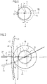
- figure 1 shows the apex surface
- figure 2 shows the resulting vertex surface used in the optimization process.
- a toroidal apex surface is used for constructing the vertex surface that is used in the optimization process for optimizing a working spectacle lens.
- figure 2 shows the shape of a spherical vertex surface as it is used in the state of the art, i.e. a vertex surface based on only a single pivot point.
- FIG. 1 The figure schematically shows an eye 1 with the cornea 3 and the apex 5 of the cornea 3.
- an eye model is used in which the movement of the eye is described by rotations about a horizontal rotation axis 7 and a vertical rotation axis 9.
- the eye 1 rotates about the horizontal rotation axis 7.
- the eye 1 rotates about a vertical rotation axis 9.
- the horizontal rotation axis 7 and the vertical rotation axis 9 are spaced from each other by a distance d which represents the smallest distance between the horizontal rotation axis 7 and the vertical rotation axis 9.
- This distance d has been found to be about 3 mm in average. However, it may also be smaller or larger and may be in the range from greater than zero up to 7.5 mm with most of the distances lying in the range between 2 mm and 4 mm. In the present exemplary embodiment, a distance d used in the eye model is 3 mm.
- Figure 1 shows a vertical section through the apex surface 11 with the vertical rotation axis 9 lying within the section.
- the section forms a circle on which the apex 5 of the cornea moves when the vertical viewing direction is changed, i.e. rotated about the horizontal rotation axis 7.
- the center of the circle is given by the point where the horizontal rotation axis 7 intersects the sectional plane.
- the apex 5 of the cornea 3 When the horizontal viewing direction of the eye 1 is changed the apex 5 of the cornea 3 also moves along a second circle.
- the center of this second circle is given by the intersection of the vertical rotation axis 9 and a horizontal sectional plane in which the horizontal rotation axis 7 lies.
- the radius of the circle in the horizontal section is larger than the radius of the circle in the vertical section.
- the apex surface in three dimensions is the surface which results from rotating the circle present in the vertical section about the vertical rotation axis 9 or by rotating the circle present in the horizontal section about the horizontal rotation axis 7.
- the result of such a rotation is a toroidal surface, i.e. a surface with circular sections in the mentioned horizontal and vertical planes but with different diameters of the respective circles.
- Figure 1 also shows a spherical surface 13 which resembles an apex surface which would result from treating the eye 1 as rotating horizontally and vertically about a single pivot point 15.
- Figure 1 shows the eye 1 in primary position.
- the viewing direction differs from the primary direction, for example when the eye 1 looks vertically upwards or downwards
- This deviation increases with increasing angle between the viewing direction and the primary direction.
- the spherical apex surface 13 represents the location of the apex 5 of the cornea 3 reasonably good for small angles between the viewing direction and the primary direction there is a considerable lack of correlation between the real position of the apex 5 of the cornea 3, which is given by the toroidal apex surface 11, and the position represented by the spherical apex surface 13.
- This is of importance, for example in case of multifocal spectacle lenses which typically include a near vision zone which, when used, requires a vertically downwards viewing direction.
- the spherical apex surface 13 does not represent a correct position of the apex 5 of the cornea 3.
- the viewing direction is represented by a visual axis which, according to the eye model used in the present exemplary embodiment, is assumed to run in normal direction of the surface of the cornea 3 at its apex 5.
- Figure 2 shows a working spectacle lens 17 used in an optimization process for optimizing a spectacle lens. It also shows a section through a vertex surface 19 which contacts the rear surface 21 of the working spectacle lens 17 at a point at which the visual axis passes the working spectacle lens 17 when the eye 1 is in primary position.
- the vertex surface 19 is constructed by adding to each point of the apex surface 11 the vertex distance vd in normal direction of the apex surface 11. In other words, the vertex distance vd is added to the apex surface 11 in a direction that corresponds, according to the eye model used, to the viewing direction of the eye 1.
- the vertex surface 19 may be represented by a point cloud formed by the ray passing points 31, 33 of the vertex surface 19.
- the three-dimensional locations of these ray passing points 31, 33 are determined by adding to points of the apex surface 11 the vertex distance vd in normal direction of the apex surface 11.
- figure 2 also shows a section through a vertex surface 23 which results from adding the vertex distance vd in normal direction to each point of the spherical apex surface 13 (as shown in figure 1 ) thus leading to a vertex surface as used in the state of the art.
- the working spectacle lens 17 is numerically represented by a number of parametrized piecewise defined functions.
- the parametrized piecewise defined functions represent the rear surface 21 of the working spectacle lens 17.
- the optimization process involves an iterative optimization of the parameters of the piecewise defined functions.
- the rear surface 21 which is optimized and thus represented by parametrized piecewise defined functions in other embodiments it is also possible to optimize the front surface of the spectacle lens.
- the front surface 25 would be represented by a number of parametrized piecewise defined functions.
- both the rear surface 21 and the front surface 25 would be represented by parametrized piecewise defined functions.
- the parametrized piecewise defined functions may, in particular, be piecewise defined continuous functions, piecewise defined continuously differentiable function and, preferably piecewise defined two times continuously differentiable functions.
- parametrized piecewise defined functions are piecewise defined polynomial functions, in particular polynomial splines like bicubic splines or splines of higher grade, polynomial non-uniform rational B-splines (NURBS), etc.
- Optimizing the working spectacle lens 17, which, in the present embodiment, means optimizing the rear surface 21, is done by iteratively optimizing the parameters of each parameterized piecewise defined function.
- the focal length of a pencil of rays emerging from an object with given object distance to the lens and passing through an area of the rear surface 21 represented by the respective piecewise defined function is calculated and the parameters of the piecewise defined functions are iteratively optimized until the calculated focal lengths based on the ray passing points on the vertex surface correspond to focal lengths which result from the prescription values given in the prescription and the target design requests.
- the as-worn conditions of the spectacle lens are considered.
- the object distance varies with the viewing direction (typically from a large object distance in primary position to a short object distance when viewing downwards), and the object distances for the different viewing directions are given by an object model.
- Figure 2 shows two exemplary pencils of rays 27, 29 one of them extending along the primary direction (reference numeral 27) and one extending along a viewing direction which corresponds to viewing vertically downwards (reference numeral 29).
- the diameters of the pencils of rays 27, 29 are given by the pupil diameter of the eye 1.
- Each pencil of rays 27, 29 includes a principal ray 35, 37 which coincides with the visual axis for the respective viewing direction.
- the principal rays 35, 37 of the pencils of rays 27, 29 pass the vertex surface 19 at passing points 31, 33 of the vertex surface 19 and run perpendicular to the vertex surface 19 at the passing points 31, 33, i.e. along the surface normals at the respective ray passing points.
- the locations of the passing points 31, 33 can be seen as representing the viewing directions which correspond to the principal rays 35, 37 passing through the respective points 31, 33.
- the principal ray 37 of the pencil of rays 29 representing a downward viewing direction runs perpendicular to the vertex surface 19 of the present exemplary embodiment but not to a spherical vertex surface 23 as it would result from only using a single pivot point.
- a principal ray running perpendicular to the spherical vertex surface 23 at its passing point through the spherical vertex surface 23 would not run perpendicular to the vertex surface 19 of the present exemplary embodiment.
- the normal of a point on the vertex surface 19 of the present exemplary embodiment represents the viewing direction of the eye 1 better than the normal of a point of a spherical vertex surface. Therefore, using the vertex surface 19 of the present exemplary embodiment allows for a more precise calculation of the focal length of a pencil of rays for a certain viewing direction than the spherical vertex surface 23 according to the state of the art does.
- focal length values result from the distances of the focal points or lines of the pencils of rays 27, 29 to the respective ray passing points 31, 33 of their principal rays 35, 37 through the vertex surface 19 along the principal ray path.
- Figure 2 shows that the ray passing point 33 of the principal ray 37 through the vertex surface 19 differs from the ray passing point of said principal ray 37 through the spherical vertex surface 23, when the wearer is looking downwards.
- the optimization of the working lens 17 is different and the optimization of the working lens 17 when using the vertex surface 19 results in a spectacle lens with smaller actual residual spherical and astigmatic errors for the wearer than the optimization according to the state of art using a spherical vertex surface which leads to a more inaccurate power calculation.
- the inventive method the actual spherical and astigmatic power values of the lens fit better to the requested power distribution according to the dioptric prescription values of the wearer and the target design requests.
- the normal directions of the toroidal vertex surface 19 shown in figure 2 represent the viewing directions more accurate than the normal directions of spherical vertex surface 23 used in the state of the art the accuracy can be improved further when not only skew rotation axes are taken into account but also a small angle of the visual axis with respect to the horizontal line when the eye 1 is in its primary position. Such an angle can be taken into account by tilting the toroidal surface. Moreover, tilting the toroidal surface can also take into account that the straight continuation of the visual axis before the eye in direction towards the retina may neither intersect the horizontal rotation axis 7 nor the vertical rotation axis 9.
- the apex surface is a toroidal apex surface.
- the apex surface may be an ellipsoid 111, as it is shown in figure 3 .
- the ray passing points - and thus the vertex surface - may be determined by adding the vertex distance vd in a direction which is given by the azimuth angle and the non-zero polar angle.
- a more complex vertex surface can be computed that is formed by points having a distance according to the vertex distance from the points of the apex surface in directions that have the defined azimuth angle and the defined non-zero polar angle.
- FIG 4 An exemplary embodiment of the computer implemented method of determining a numerical representation of a spectacle lens is shown in figure 4 in form of a flow chart.
- the method may be performed by a multipurpose data processing system such as a PC, a Notebook, a Tablet, or the like, or on a specifically dedicated data processing system.
- the data processing system may be adapted to perform the inventive method my means of a computer program comprising program code with instructions which, when executed on the data processing system, cause the data processing system to perform the inventive method.
- the computer program may be loaded into a data processing system by means of a non-volatile computer readable storage medium with the program code of the computer program stored thereon, or it may be loaded into the data processing system from a network such as, for example the internet or from a local area network.
- prescription data is loaded in step S2.
- the prescription data indicate the power values to be achieved by the numerical representation of a spectacle lens that is the result of optimizing the working spectacle lens.
- the numerical representation of a spectacle lens can then be used in a CNC-process for manufacturing a physical spectacle lens which achieves the established power.
- the power indicated by the prescription data may include spherical power, astigmatic power, prism, or any other optical characteristics of a spectacle lens.
- a target design for the numerical representation of the spectacle lens is loaded (step S3).
- the target design is an optical target design and defines a distribution or specification of residual errors over the spectacle lens in the beam path of the wearer like, for example, a residual spherical error, a residual astigmatic error, a residual prismatic error, distortion errors, magnification values, residual errors of higher order, etc.
- the residual error is defined for a number of points on a surface of the numerical representation of the spectacle lens at which the principal rays of pencils of rays pass said surface.
- the pencils of rays may be identical to the pencils of rays for which the back focal length will be determined in the optimization process.
- targets for the refractive index or the refractive index distribution may be loaded.
- step S4 data relating to the as-worn position of the spectacle lens are loaded.
- the as-worn position determines the position and orientation of the spectacle lens relative to the eyes and face of the wearer. It includes at least values for the back vertex distance, the face form angle and the as-worn pantoscopic angle and may also include the object distances that may depend on the viewing angle of the eye and furthermore may include the pupil size of the eye that defines the diameter of the pencils of ray for calculation of the optical power of the pencils of rays. Additionally thickness requests for the lens and curvature requests for the surfaces of the lens (for example base curve requests for the front surface) may be loaded.
- At least one of the prescription data, the target design and the data representing the as-worn position may be loaded into the computer from a non-volatile storage medium or from a network, e.g. from the internet or a local area network (LAN).
- a network e.g. from the internet or a local area network (LAN).
- at least one of the prescription data, the target design and the data representing the as-worn position may be input into the data processing system by means of a human machine interface such as a keyboard, a touchpad, a speech recognition system, or the like.
- prescription data, the target design and the data representing the as-worn position are successively loaded in a particular order in the present exemplary embodiment, any other order would also be possible. In addition, it would also be possible to load two or all of the prescription data, the target design and the data representing the as-worn position in parallel.
- a starting numerical representation of a working spectacle lens 17 is provided in step S5.
- the computer program may select a suitable starting numerical representation of the working spectacle lens from a repository containing a number of different starting numerical representations of working spectacle lenses which differ from each other, for example, in their base curves, in the material they are made of, in their dimensions, in their dioptric power values, etc.
- the starting numerical representation of the working spectacle lens is loaded from a storage medium or received through a network.
- the starting numerical representation of the working spectacle lens 17 includes a rear surface 21 which is given by a number of parameterized piecewise defined continuous functions as they have been described above.
- the rear surface 21 which will be optimized in the present exemplary embodiment.
- optimizing the front surface, optimizing both, the rear surface and the front surface, or optimizing the refractive index distribution of the lens material would also be possible. Therefore, it is possible that in addition to the rear surface or as an alternative to the rear surface the front surface is represented numerically by a number of piecewise defined functions.
- steps S6 and S7 starting from the starting numerical representation of the working spectacle lens 17 the numerical representation of the working spectacle lens 17 is optimized by iteratively optimizing the parameters of the piecewise defined functions. Instead or additionally, the parameters of a refractive index distribution function of the lens material may be optimized.
- step S6 The optimization is done in step S6 by use of a ray tracing process in which the actual back focal lengths for all pencils of rays 27, 29 are calculated based on the curvatures of the front surface 25 of the numerical representation of the working spectacle lens 17, on the current curvature values of the rear surface 21 of the numerical representation of the working spectacle lens 17 as defined by the current set of the parameters of the piecewise defined functions, on the physical properties of the glass material represented by the numerical representation of the working spectacle lens 17 and on the target object distances depending on the viewing direction of the eye 1 and being based on the as-worn position of the lens before the eye 1 and the pupil diameter of the eye 1.
- the position of the spectacle lens before the eye 1 and optionally the pupil diameter of the eye 1 according to the as-worn position loaded in step S4 is taken into account.
- the target focal length values are calculated from the prescription data, the target design data and from the target object distances depending on the viewing direction of the eye 1 or depending on the position of the point where the principal ray passes the front surface or the rear surface of the spectacle lens.
- the deviations from the target design can be calculated for all pencil of rays 27, 29, i.e. the spherical, astigmatic and prismatic deviations and distortion or magnification deviation from the target design can be determined. These deviations will be weighted and summed in a global merit function. Additionally, this merit function may include non-optical deviations from target values, for example deviations from wanted curvatures of the surface or from thickness requests. Furthermore the merit function may include deviations from the refractive index targets and/or deviations from the refractive index derivative targets for the lens material. Then, a value of the merit function is calculated where the value of the merit function depends on the determined deviations.
- step S6 After, in step S6, the value of the merit function has been calculated it is checked in step S7 whether the calculated value represents a minimum. In case of no, the method returns to step S6 in which at least one parameter of the parameterized piecewise defined functions or at least one parameter of the refractive index distribution function is varied and the vertex distances, the deviations and the value of the merit function are recalculated. Once it is determined in step S7 that a minimum is reached the method does not return to step S6 but proceeds to step S8 in which the optimized numerical representation of the working spectacle lens, i.e. the numerical representation with the optimized rear surface and/or the optimized front surface and/or the optimized refractive index distribution, is output as the numerical representation of the spectacle lens which was to be determined.
- the optimized numerical representation of the working spectacle lens i.e. the numerical representation with the optimized rear surface and/or the optimized front surface and/or the optimized refractive index distribution
- Outputting the optimized numerical representation of the spectacle lens can be done, e.g., by sending it over a network to a receiving party or by storing it on a non-volatile computer readable storage medium. Then the method ends (step S9) and the resulting numerical representation of a spectacle lens can be used for machining a lens blank or any other piece of optical material based on the numerical representation so as to form a spectacle lens with a surface as defined by the numerical representation of the spectacle lens.
- the calculations and determinations of the optimization process are iteratively repeated until the value of the merit function has reached a minimum. Instead ending the iterations when the value of the merit function reaches a minimum the iterations may be ended when the value of the merit function does not exceed a given threshold anymore.
- the viewing directions of the eye 1 at the ray passing points 31, 33 are represented by the normal directions of the apex surface 11 and thus of the normal direction of vertex surface 19 at the ray passing points 31, 33, or by directions given by a defined azimuth angle and a defined non-zero polar angle with respect to the normal directions of the apex surface 11 at the locations of the apex surface 19 which were used for determining the three-dimensional location of the respective ray passing points 31, 33.
- the locations of the ray passing points 31, 33 may, for example, be identified by coordinates on the vertex surface 19. These coordinates may be given, for example, in form of a first angle measured between the principal ray 35, 37 of a pencil of rays 27, 29 and the primary direction within a vertical plane including the primary direction and a second angle measured between the principal ray 35, 37 of the pencil of rays 27, 29 and the primary direction within a horizontal plane including the primary direction.
- coordinates on the vertex surface may be used, for example, the angles of spherical coordinates or three-dimensional coordinates of the surface points based on a Cartesian coordinate system.
- the principal rays 35, 37 used in the ray tracing process represent a viewing direction that corresponds to the normal direction at the ray passing point 31, 33 of the vertex surface 19.
- the principal rays 35, 37 may represent a viewing direction with a defined azimuth angle and a defined non-zero polar angle with respect to the normal direction of the apex surface 19 at the point of the apex surface 11 which was used for determining the three-dimensional location of the respective ray passing point 31, 33.
- Figure 5 shows the distribution of the residual astigmatic error of a progressive addition lens which has been optimized by use of a state of the art method. While the solid lines show the distribution of the residual astigmatic error of the lens optimized for an eye with a single pivot point the dotted lines show a recalculated distribution of the residual astigmatic error where, in the recalculation, a ray tracing is performed for the optimized spectacle lens considering a non-zero distance between the horizontal rotation axis and the vertical rotation axis.
- the spectacle lens shown in figure 5 is a progressive addition lens with a sphere of 4.00 diopter, a cylinder of 0 diopter, and an addition of 2.50 diopter with the progressive surface being the rear surface.
- the front surface is spherical with a radius of 77.34 mm.
- the glass material of the spectacle lens has a refractive index of 1.600.
- the vertex distance is 9 mm, the face form angle is 2 degree and the as-worn pantoscopic angle is 9 degree.
- the distance of the fitting cross to the tangent at the lower extremity of the lens shape is 21.0 mm
- the distance of the fitting cross to the tangent at the upper extremity of the lens shape is 11.5 mm
- the distance of the fitting cross to the tangent at the nasal extremity of the lens shape is 23.0 mm
- the distance of the fitting cross to the tangent at the temporal extremity of the lens shape is 28.5 mm.
- a mean spherical power of 6.50 diopter (4.00 diopter plus addition of 2.50 diopter) shall be achieved at the near reference point
- the target design specifies a residual astigmatic error at the near reference point of 0.14 diopter.
- the optimized mean spherical power at the near reference point is 6.56 D.
- a spherical apex surface with a radius of 12.5 mm as measured from a single pivot point of the eye is used. Together with the vertex distance of 9 mm this leads to a spherical vertex surface with a radius of 21.5 mm.
- a distance of the horizontal rotation axis from the apex of the cornea of 11 mm is used.
- the distance between the vertical rotation axis 9 and the apex 5 of the cornea 3 is set to be 14 mm.
- the vertex distance of 9 mm the vertical radius of the toroidal vertex surface is 20 mm and the horizontal radius of the toroidal vertex surface is 23 mm.
- the distance between the horizontal rotation axis 7 and the vertical rotation axis 9 is 3 mm and the pivot point of the spherical state of the art vertex surface lies in between both rotation axis.
- Figure 6 shows the distribution of the residual astigmatic error for the same spectacle lens as before but optimized with taking into account the distance between the horizontal rotation axis and the vertical rotation axis.
- the solid lines represent the residual astigmatic error according to the results of the inventive optimization process while the dotted lines represent the residual astigmatic error according to the results of the state of the art optimization process as recalculated with taking into account spaced apart rotation axis.
- the mean spherical power at the near reference point is 6.57 diopter with a residual astigmatic error of 0.14 diopter.
- the recalculation of the residual errors obtained for a lens that is optimized with the state of the art vertex surface results in a mean spherical power of 6.71 diopter together with a residual astigmatic error of 0.36 diopter.
- Figured 5 and 6 show that disregarding the distance between the horizontal rotation axis and the vertical rotation axis can lead to considerable deviations of the realized residual astigmatic error distribution from the desired residual astigmatic error distribution, respectively, in particular in the near viewing zone. Likewise, disregarding the distance between the horizontal and the vertical rotation axis leads to considerable deviations of the realized distribution of mean spherical power to the desired distribution of the mean spherical power.
- Figures 7 and 8 show a comparison of a single vision spectacle lens optimized according to the state of the art ( figure 7 ) and optimized according to the inventive method ( figure 8 ).
- the single vision spectacle lens has a spherical power of 4.00 diopter and a cylindrical power of 0.00 diopter. Its front surface is spherical with a radius of 110.67 mm and its rear surface is aspherical.
- the refractive index of the glass material of the spectacle lens is 1.664 and the edge thickness of the spectacle lens for a circular rim with a diameter of 60 mm is 0.8 mm.
- the spectacle lens is to be used with a vertex distance of 9.2 mm.
- the spectacle lens is fitted according to the conventional center of rotation requirement with the optical axis of the lens in the geometrical center of the lens.
- the aspherical rear surface of the spectacle lens was optimized according to the state of the art method, i.e. using a spherical vertex surface centered at a single pivot point and the optical axis of the lens goes through this single pivot point.
- the target for the astigmatic error given by the target design was zero over the whole lens, and with the state of the art optimization of the aspheric rear surface of the spectacle lens with a residual astigmatic error distribution that is smaller than 0.03 diopter for all viewing directions of the eye if the eye has only one pivot point was achieved. That means that the wearer has nearly no astigmatic error when viewing through any part of the whole lens if the eye has a single pivot point.
- the target of nearly no astigmatism was achieved.
- a distance between the pivot point and the rear surface of the spectacle lens of 21.7 mm was used.
- the distribution of the residual astigmatic error does not show rotational symmetry when the distribution of the residual astigmatic error is recalculated with a distance of 3 mm being present between the horizontal rotation axis and the vertical rotation axis of the eye and with the optical axis of the spectacle lens going through the horizontal and vertical rotation axis of the eye.
- the residual astigmatic error of the recalculation exceeds 0.03 D and reaches values above 0.15 D in the periphery of the spectacle lens.
- the residual astigmatic error increases noticeable when the wearer looks through the peripheral parts of the lens. If, however, for the optimization the distance of the horizontal rotation axis, i.e. the rotation axis about which the eye rotates when changing the vertical viewing direction, to the rear surface of the spectacle lens is set to 20.2 mm and the distance of the vertical rotation axis, i.e.
- the residual astigmatic error of the spectacle lens after the inventive optimization taking into account of the corresponding toroidal vertex surface does not exceed 0.05 diopter except for the outermost peripheral parts of the spectacle lens, as can be seen from figure 8 .
- the distribution of the astigmatic error over the area of the spectacle lens achieved with the optimization process according to the invention shows a much higher degree of rotational symmetry than the distribution achieved with the state of the art optimization process, as can be seen from comparing figures 7 and 8 .
- the residual astigmatic error can be further reduced if instead of an aspherical surface a freeform surface which shows axial symmetry about a horizontal axis and a vertical axis is optimized.
- a single vision spectacle lens for a purely spherical prescription would not show rotational symmetry anymore if the lens is optimized for an eye with a non-zero distance between the horizontal and the vertical rotation axis of the eye. Instead it would show axial symmetry about a horizontal axis and about a vertical axis. This is particularly true for a single vision spectacle lens for a pure spherical prescription that is fitted according to the conventional center of rotation requirement.
- step S6 after returning to step S6 after step S7 of figure 4 it may be checked whether a maximum number of iterations has been reached. In case of yes the method would end without result. In case of no a method would return to step S6.
- the distance between the horizontal rotation axis and the vertical rotation axis has a value 3 mm in the exemplary embodiments this value could be different, for example 2.8 mm, 2,5 mm 3.2 mm or 3.5 mm.
- the value could be any value greater than 0 mm up to 7.5 mm, for example, a value out of the range between 1 and 5 mm or, more specific, out of the range between 2 mm and 4 mm.
- an apex surface may be used which is derived by a measurement process.
- the measurement process may derive the three-dimensional coordinates of the locations of the apex of the cornea for a number of rotational orientations of the eye by evaluating stereoscopic images taken with the eye in the respective orientations.
- the vertex distance may be added at a defined angle with respect to the normal direction of the apex surface. Therefore, the exemplary embodiments are not meant to restrict the scope of protection of the present invention. The scope of protection shall only be delimited by the appended claims.
- the invention which has been illustrated by means of exemplary embodiments provides various advantages over the state of the art using a spherical vertex surface.
- the spherical vertex surface is based on the assumption that there is a single pivot point of the eye. This is, however only a crude approximation. In reality there is in general no single pivot point of the eye. In a much better approximation, the horizontal rotation axis about which the eye rotates for changing the vertical viewing direction has a distance to the vertical rotation axis about which the eye rotates for changing the horizontal viewing direction so that the horizontal rotation axis and the vertical rotation axis in general do not intersect.
- the straight continuation of the visual axis before the eye in direction towards the retina of the eye may have a distance to the horizontal rotation axis and/or to the vertical rotation axis. As a consequence, it may not intersect the horizontal rotation axis and/or the vertical rotation axis.
- the visual axis may run at an angle to the normal direction of the apex of the surface of the cornea. All these factors contribute to reducing the optical quality of the result of the optimization process when a spherical vertex surface is used in the optimizing process.
- the inventive way of constructing the vertex surface allows for taking into account some or all of these factors, thus allowing for a considerable improvement in the optical quality of the spectacle lens resulting from the optimization process.
Priority Applications (8)
| Application Number | Priority Date | Filing Date | Title |
|---|---|---|---|
| EP20198266.7A EP3974892A1 (de) | 2020-09-25 | 2020-09-25 | Computerimplementiertes verfahren zur bestimmung einer numerischen darstellung eines brillenglases |
| BR112023005484A BR112023005484A2 (pt) | 2020-09-25 | 2021-09-23 | Método implementado por computador de determinação de uma representação numérica de uma lente de óculos |
| PCT/EP2021/076166 WO2022063878A1 (en) | 2020-09-25 | 2021-09-23 | Computer implemented method of determining a numerical representation of a spectacle lens |
| KR1020237012137A KR102640699B1 (ko) | 2020-09-25 | 2021-09-23 | 안경 렌즈의 수치적 표현을 결정하기 위한 컴퓨터 구현 방법 |
| CN202180065182.9A CN116235097A (zh) | 2020-09-25 | 2021-09-23 | 确定眼镜镜片的数值表示的计算机实现的方法 |
| JP2023518156A JP2023542188A (ja) | 2020-09-25 | 2021-09-23 | 眼鏡レンズの数値的表現を判断するコンピュータ実施方法 |
| EP21782959.7A EP4214569B1 (de) | 2020-09-25 | 2021-09-23 | Computerimplementiertes verfahren zur bestimmung einer numerischen darstellung eines brillenglases |
| US18/187,073 US11796838B2 (en) | 2020-09-25 | 2023-03-21 | Computer implemented method of determining a numerical representation of a spectacle lens |
Applications Claiming Priority (1)
| Application Number | Priority Date | Filing Date | Title |
|---|---|---|---|
| EP20198266.7A EP3974892A1 (de) | 2020-09-25 | 2020-09-25 | Computerimplementiertes verfahren zur bestimmung einer numerischen darstellung eines brillenglases |
Publications (1)
| Publication Number | Publication Date |
|---|---|
| EP3974892A1 true EP3974892A1 (de) | 2022-03-30 |
Family
ID=72659093
Family Applications (2)
| Application Number | Title | Priority Date | Filing Date |
|---|---|---|---|
| EP20198266.7A Withdrawn EP3974892A1 (de) | 2020-09-25 | 2020-09-25 | Computerimplementiertes verfahren zur bestimmung einer numerischen darstellung eines brillenglases |
| EP21782959.7A Active EP4214569B1 (de) | 2020-09-25 | 2021-09-23 | Computerimplementiertes verfahren zur bestimmung einer numerischen darstellung eines brillenglases |
Family Applications After (1)
| Application Number | Title | Priority Date | Filing Date |
|---|---|---|---|
| EP21782959.7A Active EP4214569B1 (de) | 2020-09-25 | 2021-09-23 | Computerimplementiertes verfahren zur bestimmung einer numerischen darstellung eines brillenglases |
Country Status (7)
| Country | Link |
|---|---|
| US (1) | US11796838B2 (de) |
| EP (2) | EP3974892A1 (de) |
| JP (1) | JP2023542188A (de) |
| KR (1) | KR102640699B1 (de) |
| CN (1) | CN116235097A (de) |
| BR (1) | BR112023005484A2 (de) |
| WO (1) | WO2022063878A1 (de) |
Citations (4)
| Publication number | Priority date | Publication date | Assignee | Title |
|---|---|---|---|---|
| EP0857993A2 (de) | 1997-01-16 | 1998-08-12 | Carl Zeiss | Brillenglas mit sphärischer Vorderseite und multifokaler Rückseite, sowie Verfahren zu seiner Herstellung |
| US6382789B1 (en) | 1998-09-28 | 2002-05-07 | Essilor International | Toric ophthalmic lenses |
| EP1744203A1 (de) | 2004-05-05 | 2007-01-17 | INDO Internacional, S.A. | Berechnungsverfahren für augenoptische linsen und entsprechende linse |
| DE102017118219A1 (de) | 2017-08-10 | 2019-02-14 | Carl Zeiss Vision International Gmbh | Computerimplementiertes Verfahren zum Erstellen eines Zieldesigns für die Optimierung einer Freiformfläche eines Brillenglases, Computerprogramm, Speichermedium und Computer |
Family Cites Families (12)
| Publication number | Priority date | Publication date | Assignee | Title |
|---|---|---|---|---|
| DE19960826A1 (de) * | 1999-12-16 | 2001-07-05 | Rodenstock Optik G | Einstärken-Brillenglas mit Vollkorrektion |
| DE102009010467A1 (de) * | 2009-02-26 | 2010-09-09 | Carl Zeiss Vision Gmbh | Verfahren und Vorrichtung zur Bestimmung der Augendrehpunktlage |
| DE102012010221A1 (de) * | 2012-05-23 | 2013-11-28 | Carl Zeiss Vision International Gmbh | Verfahren zum Herstellen einer Brillenlinse mit astigmatischer Korrektur und Brille mit solcher Brillenlinse |
| EP3074810B1 (de) | 2013-11-25 | 2017-11-15 | Essilor International (Compagnie Générale d'Optique) | Verfahren zur bereitstellung eines individuell angepassten gleitsichtbrillenglases an einen träger |
| DE102016113374B3 (de) | 2016-07-20 | 2017-10-26 | Carl Zeiss Vision International Gmbh | Fern-Durchblickpunkt-Bestimmung für ein Brillenglas |
| WO2016050664A1 (en) | 2014-09-30 | 2016-04-07 | Essilor International (Compagnie Generale D'optique) | A multifocal lens supply system for providing to a wearer a customized progressive spectacle ophthalmic lens |
| CN107003540B (zh) * | 2014-12-08 | 2020-05-26 | 依视路国际公司 | 由计算机装置实施的用于计算配戴者的眼镜眼科镜片的镜片光学系统的方法 |
| KR102580793B1 (ko) * | 2015-10-15 | 2023-09-20 | 에씰로 앙터나시오날 | 근시 또는 정시 노안 착용자를 위한 안과용 누진 가법 렌즈 및 그러한 렌즈를 제공하는 방법 |
| WO2018022042A1 (en) * | 2016-07-27 | 2018-02-01 | Carl Zeiss Vision International Gmbh | Method for determining an improved design for a progressive lens taking into account higher order aberrations of the eye |
| US20180307058A1 (en) | 2017-04-21 | 2018-10-25 | Carl Zeiss Vision International Gmbh | Computer implemented method of determining a base curve for a spectacle lens and method of manufacturing a spectacle lens |
| DE102017118721B4 (de) | 2017-08-16 | 2023-03-30 | Carl Zeiss Vision International Gmbh | Computerimplementiertes Verfahren und Vorrichtung zum Transformieren einer Mehrzahl an ersten Punkten einer ersten Brillenglasfläche in eine Mehrzahl an zweiten Punkten einer zweiten Brillenglasfläche, computerimplementiertes Verfahren und Vorrichtung zum Bestimmen eines Zielbrillenglases mit einer optimierten Brillenglasfläche und Computerprogramm |
| JP2019144277A (ja) | 2017-12-28 | 2019-08-29 | ホヤ レンズ タイランド リミテッドHOYA Lens Thailand Ltd | 眼鏡レンズおよび眼鏡レンズを製造するための方法 |
-
2020
- 2020-09-25 EP EP20198266.7A patent/EP3974892A1/de not_active Withdrawn
-
2021
- 2021-09-23 JP JP2023518156A patent/JP2023542188A/ja active Pending
- 2021-09-23 CN CN202180065182.9A patent/CN116235097A/zh active Pending
- 2021-09-23 BR BR112023005484A patent/BR112023005484A2/pt unknown
- 2021-09-23 WO PCT/EP2021/076166 patent/WO2022063878A1/en active Search and Examination
- 2021-09-23 EP EP21782959.7A patent/EP4214569B1/de active Active
- 2021-09-23 KR KR1020237012137A patent/KR102640699B1/ko active IP Right Grant
-
2023
- 2023-03-21 US US18/187,073 patent/US11796838B2/en active Active
Patent Citations (4)
| Publication number | Priority date | Publication date | Assignee | Title |
|---|---|---|---|---|
| EP0857993A2 (de) | 1997-01-16 | 1998-08-12 | Carl Zeiss | Brillenglas mit sphärischer Vorderseite und multifokaler Rückseite, sowie Verfahren zu seiner Herstellung |
| US6382789B1 (en) | 1998-09-28 | 2002-05-07 | Essilor International | Toric ophthalmic lenses |
| EP1744203A1 (de) | 2004-05-05 | 2007-01-17 | INDO Internacional, S.A. | Berechnungsverfahren für augenoptische linsen und entsprechende linse |
| DE102017118219A1 (de) | 2017-08-10 | 2019-02-14 | Carl Zeiss Vision International Gmbh | Computerimplementiertes Verfahren zum Erstellen eines Zieldesigns für die Optimierung einer Freiformfläche eines Brillenglases, Computerprogramm, Speichermedium und Computer |
Non-Patent Citations (5)
| Title |
|---|
| FRY G A ET AL: "THE CENTER OF ROTATION OF THE EYE", AMERICAN JOURNAL OF OPTOMETRY AND ARCHIVES OF AMERICAN ACADEMY OFOPTOMETRY, AMERICAN JOURNAL OF OPTOMETRY PUB., MINNEAPOLIS, US, vol. 39, 1 November 1962 (1962-11-01), pages 581 - 595, XP009055840, ISSN: 0002-9408 * |
| HELMUT GOERSCH: "Worterbuch der Optometrie", 2004, DOZ-VERLAG |
| JALIE MO: "The role of the eye's centre of rotation in lens design", 31 October 2013 (2013-10-31), XP055790503, Retrieved from the Internet <URL:https://www.pointsdevue.com/article/role-eyes-centre-rotation-lens-design> [retrieved on 20210326] * |
| KAI SCHREIBER: "Erstellung und Optimierung von Algorithmen zur Messung von Augenbewegungen mittels Video-Okulographie-Methoden", TUBINGEN, 22 January 1999 (1999-01-22) |
| SCHREIBER KAI: "Erstellung und Optimierung von Algorithmen zur Messung von Augenbewegungen mittels Video-Okulographie-Methoden", 22 January 1999 (1999-01-22), XP055790897, Retrieved from the Internet <URL:http://work.thaslwanter.at/PDFs/Theses/Dipl_Schreiber_1999.pdf> [retrieved on 20210329] * |
Also Published As
| Publication number | Publication date |
|---|---|
| KR102640699B1 (ko) | 2024-02-27 |
| EP4214569C0 (de) | 2023-11-15 |
| EP4214569B1 (de) | 2023-11-15 |
| BR112023005484A2 (pt) | 2023-05-09 |
| KR20230058169A (ko) | 2023-05-02 |
| US20230229019A1 (en) | 2023-07-20 |
| CN116235097A (zh) | 2023-06-06 |
| EP4214569A1 (de) | 2023-07-26 |
| JP2023542188A (ja) | 2023-10-05 |
| WO2022063878A1 (en) | 2022-03-31 |
| US11796838B2 (en) | 2023-10-24 |
Similar Documents
| Publication | Publication Date | Title |
|---|---|---|
| CN113196144B (zh) | 具有可变折射率的渐变焦度眼镜片及其设计与制造方法 | |
| KR100608406B1 (ko) | 안경 렌즈 및 그 제조방법 | |
| JP5918137B2 (ja) | 光学関数決定方法 | |
| JP4067277B2 (ja) | 累進屈折力眼鏡レンズ及びその設計方法 | |
| CN101960360B (zh) | 根据给定的眼镜架计算光学系统的方法 | |
| US6789898B2 (en) | Model for representing an ophthalmic lens surface | |
| KR20150081288A (ko) | 안과용 렌즈의 광학 파라미터 결정 방법 | |
| KR20200057709A (ko) | 안구 렌즈를 평가하기 위한 방법, 연관된 평가 시스템 및 안구 렌즈를 제조하기 위한 산업용 조립체 | |
| EP3974892A1 (de) | Computerimplementiertes verfahren zur bestimmung einer numerischen darstellung eines brillenglases | |
| US11372263B2 (en) | Bifocal spectacle lens, computer implemented method for creating a numerical representation of same, computer program, data processing system, and non-volatile computer readable storage medium | |
| CN112602001B (zh) | 用于生成目标设计的计算机实施的方法、数据处理系统和存储介质及相关方法和存储介质 | |
| KR20150083860A (ko) | 안과용 렌즈의 실현 가능성 결정 방법 | |
| JPWO2022063878A5 (de) |
Legal Events
| Date | Code | Title | Description |
|---|---|---|---|
| PUAI | Public reference made under article 153(3) epc to a published international application that has entered the european phase |
Free format text: ORIGINAL CODE: 0009012 |
|
| STAA | Information on the status of an ep patent application or granted ep patent |
Free format text: STATUS: THE APPLICATION HAS BEEN PUBLISHED |
|
| AK | Designated contracting states |
Kind code of ref document: A1 Designated state(s): AL AT BE BG CH CY CZ DE DK EE ES FI FR GB GR HR HU IE IS IT LI LT LU LV MC MK MT NL NO PL PT RO RS SE SI SK SM TR |
|
| STAA | Information on the status of an ep patent application or granted ep patent |
Free format text: STATUS: THE APPLICATION IS DEEMED TO BE WITHDRAWN |
|
| 18D | Application deemed to be withdrawn |
Effective date: 20221001 |