EP3974749B1 - Belüftungseinheit für einen tiefkühlschrank und verfahren zum betreiben einer solchen belüftungseinheit - Google Patents
Belüftungseinheit für einen tiefkühlschrank und verfahren zum betreiben einer solchen belüftungseinheit Download PDFInfo
- Publication number
- EP3974749B1 EP3974749B1 EP21194110.9A EP21194110A EP3974749B1 EP 3974749 B1 EP3974749 B1 EP 3974749B1 EP 21194110 A EP21194110 A EP 21194110A EP 3974749 B1 EP3974749 B1 EP 3974749B1
- Authority
- EP
- European Patent Office
- Prior art keywords
- heating element
- ventilation unit
- door
- pipe
- interior
- Prior art date
- Legal status (The legal status is an assumption and is not a legal conclusion. Google has not performed a legal analysis and makes no representation as to the accuracy of the status listed.)
- Active
Links
Images


Classifications
-
- F—MECHANICAL ENGINEERING; LIGHTING; HEATING; WEAPONS; BLASTING
- F25—REFRIGERATION OR COOLING; COMBINED HEATING AND REFRIGERATION SYSTEMS; HEAT PUMP SYSTEMS; MANUFACTURE OR STORAGE OF ICE; LIQUEFACTION SOLIDIFICATION OF GASES
- F25D—REFRIGERATORS; COLD ROOMS; ICE-BOXES; COOLING OR FREEZING APPARATUS NOT OTHERWISE PROVIDED FOR
- F25D21/00—Defrosting; Preventing frosting; Removing condensed or defrost water
- F25D21/04—Preventing the formation of frost or condensate
-
- F—MECHANICAL ENGINEERING; LIGHTING; HEATING; WEAPONS; BLASTING
- F25—REFRIGERATION OR COOLING; COMBINED HEATING AND REFRIGERATION SYSTEMS; HEAT PUMP SYSTEMS; MANUFACTURE OR STORAGE OF ICE; LIQUEFACTION SOLIDIFICATION OF GASES
- F25D—REFRIGERATORS; COLD ROOMS; ICE-BOXES; COOLING OR FREEZING APPARATUS NOT OTHERWISE PROVIDED FOR
- F25D17/00—Arrangements for circulating cooling fluids; Arrangements for circulating gas, e.g. air, within refrigerated spaces
- F25D17/04—Arrangements for circulating cooling fluids; Arrangements for circulating gas, e.g. air, within refrigerated spaces for circulating air, e.g. by convection
- F25D17/042—Air treating means within refrigerated spaces
- F25D17/045—Air flow control arrangements
-
- F—MECHANICAL ENGINEERING; LIGHTING; HEATING; WEAPONS; BLASTING
- F25—REFRIGERATION OR COOLING; COMBINED HEATING AND REFRIGERATION SYSTEMS; HEAT PUMP SYSTEMS; MANUFACTURE OR STORAGE OF ICE; LIQUEFACTION SOLIDIFICATION OF GASES
- F25D—REFRIGERATORS; COLD ROOMS; ICE-BOXES; COOLING OR FREEZING APPARATUS NOT OTHERWISE PROVIDED FOR
- F25D11/00—Self-contained movable devices, e.g. domestic refrigerators
-
- F—MECHANICAL ENGINEERING; LIGHTING; HEATING; WEAPONS; BLASTING
- F25—REFRIGERATION OR COOLING; COMBINED HEATING AND REFRIGERATION SYSTEMS; HEAT PUMP SYSTEMS; MANUFACTURE OR STORAGE OF ICE; LIQUEFACTION SOLIDIFICATION OF GASES
- F25D—REFRIGERATORS; COLD ROOMS; ICE-BOXES; COOLING OR FREEZING APPARATUS NOT OTHERWISE PROVIDED FOR
- F25D17/00—Arrangements for circulating cooling fluids; Arrangements for circulating gas, e.g. air, within refrigerated spaces
- F25D17/04—Arrangements for circulating cooling fluids; Arrangements for circulating gas, e.g. air, within refrigerated spaces for circulating air, e.g. by convection
- F25D17/042—Air treating means within refrigerated spaces
- F25D17/047—Pressure equalising devices
-
- F—MECHANICAL ENGINEERING; LIGHTING; HEATING; WEAPONS; BLASTING
- F25—REFRIGERATION OR COOLING; COMBINED HEATING AND REFRIGERATION SYSTEMS; HEAT PUMP SYSTEMS; MANUFACTURE OR STORAGE OF ICE; LIQUEFACTION SOLIDIFICATION OF GASES
- F25D—REFRIGERATORS; COLD ROOMS; ICE-BOXES; COOLING OR FREEZING APPARATUS NOT OTHERWISE PROVIDED FOR
- F25D21/00—Defrosting; Preventing frosting; Removing condensed or defrost water
- F25D21/002—Defroster control
-
- F—MECHANICAL ENGINEERING; LIGHTING; HEATING; WEAPONS; BLASTING
- F25—REFRIGERATION OR COOLING; COMBINED HEATING AND REFRIGERATION SYSTEMS; HEAT PUMP SYSTEMS; MANUFACTURE OR STORAGE OF ICE; LIQUEFACTION SOLIDIFICATION OF GASES
- F25D—REFRIGERATORS; COLD ROOMS; ICE-BOXES; COOLING OR FREEZING APPARATUS NOT OTHERWISE PROVIDED FOR
- F25D21/00—Defrosting; Preventing frosting; Removing condensed or defrost water
- F25D21/06—Removing frost
- F25D21/08—Removing frost by electric heating
-
- F—MECHANICAL ENGINEERING; LIGHTING; HEATING; WEAPONS; BLASTING
- F25—REFRIGERATION OR COOLING; COMBINED HEATING AND REFRIGERATION SYSTEMS; HEAT PUMP SYSTEMS; MANUFACTURE OR STORAGE OF ICE; LIQUEFACTION SOLIDIFICATION OF GASES
- F25D—REFRIGERATORS; COLD ROOMS; ICE-BOXES; COOLING OR FREEZING APPARATUS NOT OTHERWISE PROVIDED FOR
- F25D23/00—General constructional features
- F25D23/02—Doors; Covers
- F25D23/028—Details
-
- F—MECHANICAL ENGINEERING; LIGHTING; HEATING; WEAPONS; BLASTING
- F25—REFRIGERATION OR COOLING; COMBINED HEATING AND REFRIGERATION SYSTEMS; HEAT PUMP SYSTEMS; MANUFACTURE OR STORAGE OF ICE; LIQUEFACTION SOLIDIFICATION OF GASES
- F25D—REFRIGERATORS; COLD ROOMS; ICE-BOXES; COOLING OR FREEZING APPARATUS NOT OTHERWISE PROVIDED FOR
- F25D23/00—General constructional features
- F25D23/12—Arrangements of compartments additional to cooling compartments; Combinations of refrigerators with other equipment, e.g. stove
-
- F—MECHANICAL ENGINEERING; LIGHTING; HEATING; WEAPONS; BLASTING
- F25—REFRIGERATION OR COOLING; COMBINED HEATING AND REFRIGERATION SYSTEMS; HEAT PUMP SYSTEMS; MANUFACTURE OR STORAGE OF ICE; LIQUEFACTION SOLIDIFICATION OF GASES
- F25D—REFRIGERATORS; COLD ROOMS; ICE-BOXES; COOLING OR FREEZING APPARATUS NOT OTHERWISE PROVIDED FOR
- F25D29/00—Arrangement or mounting of control or safety devices
-
- F—MECHANICAL ENGINEERING; LIGHTING; HEATING; WEAPONS; BLASTING
- F25—REFRIGERATION OR COOLING; COMBINED HEATING AND REFRIGERATION SYSTEMS; HEAT PUMP SYSTEMS; MANUFACTURE OR STORAGE OF ICE; LIQUEFACTION SOLIDIFICATION OF GASES
- F25D—REFRIGERATORS; COLD ROOMS; ICE-BOXES; COOLING OR FREEZING APPARATUS NOT OTHERWISE PROVIDED FOR
- F25D2201/00—Insulation
- F25D2201/10—Insulation with respect to heat
- F25D2201/12—Insulation with respect to heat using an insulating packing material
- F25D2201/126—Insulation with respect to heat using an insulating packing material of cellular type
- F25D2201/1262—Insulation with respect to heat using an insulating packing material of cellular type with open cells
-
- F—MECHANICAL ENGINEERING; LIGHTING; HEATING; WEAPONS; BLASTING
- F25—REFRIGERATION OR COOLING; COMBINED HEATING AND REFRIGERATION SYSTEMS; HEAT PUMP SYSTEMS; MANUFACTURE OR STORAGE OF ICE; LIQUEFACTION SOLIDIFICATION OF GASES
- F25D—REFRIGERATORS; COLD ROOMS; ICE-BOXES; COOLING OR FREEZING APPARATUS NOT OTHERWISE PROVIDED FOR
- F25D2400/00—General features of, or devices for refrigerators, cold rooms, ice-boxes, or for cooling or freezing apparatus not covered by any other subclass
- F25D2400/02—Refrigerators including a heater
-
- F—MECHANICAL ENGINEERING; LIGHTING; HEATING; WEAPONS; BLASTING
- F25—REFRIGERATION OR COOLING; COMBINED HEATING AND REFRIGERATION SYSTEMS; HEAT PUMP SYSTEMS; MANUFACTURE OR STORAGE OF ICE; LIQUEFACTION SOLIDIFICATION OF GASES
- F25D—REFRIGERATORS; COLD ROOMS; ICE-BOXES; COOLING OR FREEZING APPARATUS NOT OTHERWISE PROVIDED FOR
- F25D2600/00—Control issues
- F25D2600/02—Timing
-
- F—MECHANICAL ENGINEERING; LIGHTING; HEATING; WEAPONS; BLASTING
- F25—REFRIGERATION OR COOLING; COMBINED HEATING AND REFRIGERATION SYSTEMS; HEAT PUMP SYSTEMS; MANUFACTURE OR STORAGE OF ICE; LIQUEFACTION SOLIDIFICATION OF GASES
- F25D—REFRIGERATORS; COLD ROOMS; ICE-BOXES; COOLING OR FREEZING APPARATUS NOT OTHERWISE PROVIDED FOR
- F25D2700/00—Means for sensing or measuring; Sensors therefor
- F25D2700/02—Sensors detecting door opening
Definitions
- the invention relates to a ventilation unit for a freezer.
- a well-known phenomenon in various types of refrigerators is that after closing a door, it initially cannot be opened again, or only with considerable force. This phenomenon can be attributed to the temperature dependence of air density. As temperature decreases, the air density increases, and the specific volume of the air decreases accordingly.
- a ventilation unit for a freezer having the features of patent claim 1 by a freezer having the features of patent claim 5 and by a method according to the features of claim 9.
- the at least one heating element is activated simultaneously with the detection of the door opening.
- the ventilation device can be opened when the door is subsequently closed, allowing pressure equalization between the environment and the interior. This allows, in particular, the fact that there is typically a connection between the opening of the door and the occurrence of a pressure difference between the interior and the environment to be taken into account.
- the temperature difference and/or the pressure difference between the interior and the environment are taken into account in determining the time period.
- the pressure difference and/or the temperature difference between the interior and the environment are preferably monitored.
- Large pressure and/or temperature differences preferably extend the time period. For small pressure and/or temperature differences, the procedure can be modified so that the time period is shortened accordingly.
- the time period can be determined based on the interval time that has elapsed since the heating element was last deactivated and/or the last heating period between the last activation and deactivation of the heating element.
- Heating the ventilation element during this period preferably serves to keep the ventilation unit open, i.e. ice-free, for a sufficiently long time after the door has been closed in order to allow pressure equalization. If the last activity of the heating element was sufficiently recent, residual heat may still be present in the ventilation element, which can help keep the ventilation unit open. Typically, the shorter the time since the last activity of the heating element, the more residual heat is present. The operation of the ventilation unit can therefore be designed such that a short interval time allows the time period to be shortened.
- the duration of the last activity of the heating element, the last heating period can also provide an indication of how much residual heat is present in the ventilation unit.
- the method is therefore designed in such a way that the last heating period, i.e. the duration of the last activity of the heating element, has a shortening effect on the time period.
- Figure 1 shows a ventilation unit 10 arranged in a door 44 with a pipe 20 and a heating element 30.
- An air-permeable filling material which can be designed as a wire mesh 12, is arranged in the pipe 20.
- the intended use of the ventilation unit 10 is preferably to create a pressure difference 82 (see Fig. 3 ) between two spaces, in particular an interior space 46 and an environment 50 (see Fig. 2 ).
- a pressure difference 82 see Fig. 3
- the Pipeline 20 preferably has a flow direction 28.
- FIG 4 shows a freezer designed as an ultra-low freezer 40 with a ventilation unit 10.
- the ventilation unit 10 When the ventilation unit 10 is used in the ultra-low freezer 40, the pipe 20 and the wire mesh 12 arranged therein can ice over due to the temperatures prevailing in the ultra-low freezer 40.
- the icing occurs, for example, when condensate from the air precipitates and freezes.
- the cross-section of the pipe 20 can be reduced or even completely closed.
- an ice plug is preferably arranged in the pipe 20.
- An air flow through the ventilation unit 10 can thus be reduced or completely stopped. This effect can be intentional, in particular to prevent undesired air flows through the ventilation unit 10, and can be promoted by arranging the wire mesh 12 in the pipe 20.
- the ventilation unit 10 By activating the heating element 30, the ventilation unit 10 can be defrosted, i.e. opened, or kept free of ice, i.e. kept open.
- FIG 1 shows further details of the ventilation unit 10.
- the pipe 20 preferably has a first end 22, a second end 24, and a pipe longitudinal axis 26.
- the pipe 20 can be straight or at least have a bend.
- the pipe 20 is made of a material with high thermal conductivity, in particular of a metallic material.
- the high thermal conductivity can, in particular, enable rapid de-icing of the ventilation unit 10.
- the pipe 20 can for example a round cross-section 98 ( Figure 2 ) or a square cross-section 99 ( Figure 3 ).
- the knitted wire mesh 12 is preferably arranged in the pipeline 20 such that it completely fills the cross-section of the pipeline 20.
- the knitted wire mesh 12 is preferably a spatial structure made of wire, in which gaps are arranged between the individual wires or wire strands. Water condensing from the air can precipitate on the wires or wire strands as well as on the pipeline 20.
- the gaps are referred to as pores and can ensure the air permeability of the knitted wire mesh 12.
- the size of the pores is preferably selected to be small enough that the pores can freeze due to condensation water precipitating on the knitted wire mesh 12. At the same time, the size of the pores is preferably selected to be large enough that a sufficiently large air flow through the knitted wire mesh 12 is possible when the pores are open, i.e., not frozen.
- the wire mesh 12 can be elastic. In particular, it can be designed as a sponge-like structure. The elasticity of the wire mesh 12 can be adjusted, in particular, by the size of the pores and the thickness of the wire strands used. A wire mesh 12 made of thin wire strands can be particularly advantageous for use in a ventilation unit 10, since it allows for the creation of a very fine pore structure.
- the heating element 30 can be designed as an electrical heating element.
- the heating element 30 is supplied with energy via cable 32.
- the heating element 30 is arranged on the outside of the pipe 20 in the circumferential direction around the Pipe 20 is arranged.
- the heating element 30 is preferably arranged in the section of the pipe 20 in which the wire mesh 12 is arranged. In this way, the heat conduction path from the heating element 30 to the wire mesh 12 can be kept short.
- the time delay between the activation of the heating element 30 and the heating of the wire mesh 12 can be kept short. In this way, dynamic heating of the wire mesh 12 can be realized. This also minimizes the time delay between the activation of the at least one heating element 30 and the opening of the pores.
- the pipeline 20 has a securing element for securing the wire mesh 12.
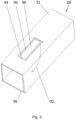
- Figure 2 and Figure 3 show exemplary embodiments of a pipeline 20 in which the securing element is formed by a tab 90 according to the invention.
- the tab 90 is formed by a contour of the tab 90 being cut out at least in sections from a wall 21 of the pipeline 20, so that the contour has a cut-out section 96.
- the tab 90 is bent into the cross-section of the pipeline 20 at a non-cut-out section 94 of the contour in the bending direction 92.
- the non-cut-out section 94 is preferably perforated to facilitate bending.
- the cutting can be carried out in particular by laser cutting or punching.
- the securing element can be manufactured particularly cost-effectively.
- the illustration in Figure 2 shows the pipeline 20 in a manufacturing step in which the tab 90 has already been cut out but not yet bent into the cross-section.
- Figure 3 shows a pipeline 20 in which the tab 90 is bent into the cross section of the pipeline 20.
- the ultra-low temperature freezer 40 preferably has a control range of -90°C to -40°C.
- the ultra-low temperature freezer has a housing 42 in which the interior space 46 is arranged.
- the ultra-low temperature freezer 40 has the door 44 and the ventilation unit 10.
- the interior space 46 is referred to in particular as the space enclosed by the housing 42 and the door 44 when the door 44 is closed.
- the ventilation unit 10 is preferably arranged in the door 44 such that the first end 22 of the pipe 20 opens into the interior space 46 when the door 44 is closed, and a second end 24 of the pipe 20 opens into the environment 50.
- the environment 50 is preferably formed by the space arranged outside the ultra-low temperature freezer 40.
- the temperature in the interior 46 is below the ambient temperature 50.
- the pipe 20 may be frozen and thus blocked by an ice plug. Ice plugs are preferably formed by condensation that has settled on the wire mesh 12.
- the environment 50 and the interior 46 can thus be separated by the housing 42 and the door 44 of the ultra-low temperature freezer 40.
- a pressure difference 82 can occur between the interior space 46 and the surroundings 50. This is typically the case when, for example, warm air from the surroundings 50 has entered the interior space 46 due to the temporary opening of the door 44. There, the air is usually cooled, whereby its volume decreases and the pressure in the interior space 46 drops compared to the surroundings 50. Typically, there is a connection between the opening of the door 44 and the creation of a pressure difference 82. A pressure difference 82 can be compensated for by allowing air from the surroundings 50 to flow into the interior space 46.
- the ventilation unit 10 can establish a connection between the interior 46 and the environment 50.
- the connection is preferably established by activating the heating element 30, thus defrosting the ice plug and opening the ventilation unit 10. This allows air to flow into the interior 46.
- the typical pressure gradient preferably results in a flow direction 28 through the pipe 20 from the environment 50 to the interior 46.
- the closing of the pipe 20 is preferably carried out by deactivating the heating element 30.
- the pipe 20 and the wire mesh 12 of the ventilation element 10 can be cooled by the low temperatures prevailing in the interior 46.
- Water can condense out of the air in the pipe 20 and form a new ice plug.
- the heating element 30 is preferably activated by opening the door 44.
- the ultra-low temperature freezer 40 may have an opening sensor 48 that can detect the opening of the door 44.
- the heating element 30 is thereby activated after a certain period of time 66 (see Fig. 3 and 4) are deactivated after closing at least one door 44.
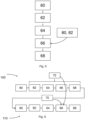
- Figure 5 shows a flow diagram of a first method for operating the ventilation device 10 in the ultra-low freezer 40.
- an activation 62 of the heating element 30 takes place.
- a deactivation 68 of the heating element 30 takes place after the expiration of the specific time period 66.
- the activation 62 of the heating element 30 occurs without a time delay with the detection 60 of the opening of the door 44. This makes it possible to ensure that the ventilation device 10 is open when the door 44 is subsequently closed, so that pressure equalization can take place between the environment 50 and the interior 46. This makes it possible, in particular, to take into account the fact that there is typically a connection between the opening of the door 44 and the occurrence of a pressure difference 82 between the interior 46 and the environment 50.
- the time period 66 is preferably chosen to be long enough for the pressure difference 82 between the environment 50 and the interior 46 caused by the opening and closing of the door 44 after the door 44 is closed. With the help of the time period 66, it is possible to take into account in particular the fact that the pressure difference 82 does not occur immediately in its maximum form after the door 44 is closed, but has a temporal progression.
- the ultra-low freezer 40 can be configured such that the time period 66 can be defined by presetting. A value of three minutes has proven particularly advantageous.
- the time period 66 can also be determined or influenced by incorporating data entered by the user and/or determined by sensors. Such data can be the pressure difference 82 and/or a temperature difference 80 between the interior 46 and the surrounding area 50. Large pressure differences 82 and/or temperature differences 80 preferably extend the time period 66. In the case of small pressure differences 82 and/or temperature differences 80, the method can be modified such that the time period 66 is shortened accordingly.
- the time period 66 of a current opening cycle 110 when determining the time period 66 of a current opening cycle 110, reference can be made to a most recently performed, i.e., last opening cycle 100.
- an interval time 70 elapsed since the last deactivation 68 of the heating element 30 and/or a last heating duration 72 between the last activation 62 and deactivation 68 of the heating element 30 can be included in the determination of the time period 66.
- the heating of the ventilation element 10 during the time period 66 preferably serves to keep the ventilation unit 10 open, i.e., ice-free, for a sufficiently long time after the door 44 has been closed in order to allow pressure equalization.
- the ventilation element 10 residual heat may still be present, which can help keep the ventilation unit 10 open.
- the more residual heat is present the shorter the time since the last activity of the heating element, i.e., the shorter the interval time 70.
- the operation of the ventilation unit 10 can therefore be designed such that a short interval time 70 enables a shortening of the time period 66 of the current opening cycle 110.
- the duration of the last activity of the heating element 30, the last heating period 72 can also provide an indication of how much residual heat is present in the ventilation unit 10.
- the method is therefore preferably designed such that a long last heating period 72 has a shortening effect on the time period 66.
- the method for operating the ventilation unit 10 can in particular be implemented as a combination of the first, in Figure 5 depicted, and the second, in Figure 6 illustrated method, so that both the temperature difference 80 and/or the pressure difference 82 as well as the interval time 70 and/or the last heating duration 72 are taken into account when determining the time period 66.
Landscapes
- Engineering & Computer Science (AREA)
- Chemical & Material Sciences (AREA)
- Combustion & Propulsion (AREA)
- Physics & Mathematics (AREA)
- Mechanical Engineering (AREA)
- Thermal Sciences (AREA)
- General Engineering & Computer Science (AREA)
- Cold Air Circulating Systems And Constructional Details In Refrigerators (AREA)
Applications Claiming Priority (1)
| Application Number | Priority Date | Filing Date | Title |
|---|---|---|---|
| DE102020125126.2A DE102020125126A1 (de) | 2020-09-25 | 2020-09-25 | Belüftungseinheit für einen Tiefkühlschrank |
Publications (2)
| Publication Number | Publication Date |
|---|---|
| EP3974749A1 EP3974749A1 (de) | 2022-03-30 |
| EP3974749B1 true EP3974749B1 (de) | 2025-06-25 |
Family
ID=77595318
Family Applications (1)
| Application Number | Title | Priority Date | Filing Date |
|---|---|---|---|
| EP21194110.9A Active EP3974749B1 (de) | 2020-09-25 | 2021-08-31 | Belüftungseinheit für einen tiefkühlschrank und verfahren zum betreiben einer solchen belüftungseinheit |
Country Status (5)
| Country | Link |
|---|---|
| US (1) | US11906234B2 (pl) |
| EP (1) | EP3974749B1 (pl) |
| CN (1) | CN114251907A (pl) |
| DE (1) | DE102020125126A1 (pl) |
| PL (1) | PL3974749T3 (pl) |
Citations (1)
| Publication number | Priority date | Publication date | Assignee | Title |
|---|---|---|---|---|
| US4662270A (en) * | 1985-08-30 | 1987-05-05 | Kolpack Industries Inc. | Door jamb post and valved vent passage with heater |
Family Cites Families (18)
| Publication number | Priority date | Publication date | Assignee | Title |
|---|---|---|---|---|
| US3680329A (en) | 1971-02-18 | 1972-08-01 | Emhart Corp | Pressure equalizing valve |
| BE795150A (fr) * | 1972-02-14 | 1973-05-29 | Braun Ag | Ventilateur deplacable |
| US4257445A (en) | 1978-10-26 | 1981-03-24 | Buildex Incorporated | Shielded vent port |
| US4569208A (en) | 1984-12-07 | 1986-02-11 | Buildex Incorporated | Pressure relief port |
| FR2723285B1 (fr) * | 1994-07-26 | 1996-09-06 | Seb Sa | Element chauffant blinde silencieux |
| CA2160338C (en) | 1994-10-13 | 2003-09-23 | Kenneth W. Oden | Electronic refrigeration control system |
| US6223817B1 (en) * | 1996-04-25 | 2001-05-01 | Royal Vendors, Inc. | Electronic refrigeration control system |
| US6397620B1 (en) | 2000-11-06 | 2002-06-04 | Spx Corporation | Ultra-low temperature freezer cabinet utilizing vacuum insulated panels |
| US6374620B1 (en) | 2001-04-23 | 2002-04-23 | Opx Corporation | Pressure equalization port |
| US20050160754A1 (en) | 2004-01-23 | 2005-07-28 | Hugh Mark A. | Vacuum relief assembly |
| CN2831003Y (zh) * | 2005-09-25 | 2006-10-25 | 海尔集团公司 | 冷柜压力平衡器 |
| US7340916B2 (en) | 2005-11-17 | 2008-03-11 | Kim Brian S | Pressure equalizing device for refrigerators |
| DE202014008327U1 (de) | 2014-10-21 | 2016-01-22 | Eppendorf Ag | Ventilanordnung zum Belüften eines Innenraums eines Tiefkühlgeräts |
| KR101643641B1 (ko) | 2014-12-04 | 2016-07-29 | 엘지전자 주식회사 | 냉장고 |
| CN106422592A (zh) * | 2016-06-23 | 2017-02-22 | 苏州骏发精密机械有限公司 | 一种固定管道内过滤器的夹具 |
| CN107270616B (zh) * | 2017-06-27 | 2022-02-15 | 安徽康佳同创电器有限公司 | 冰箱间室压力平衡装置及冰箱 |
| CN110752462B (zh) * | 2019-10-09 | 2025-06-17 | 中航光电科技股份有限公司 | 一种共轴连接器及其外导体 |
| CN110806050B (zh) * | 2019-11-07 | 2022-12-30 | 青岛海尔特种电冰柜有限公司 | 一种气压平衡装置及使用该气压平衡装置的冷藏装置 |
-
2020
- 2020-09-25 DE DE102020125126.2A patent/DE102020125126A1/de active Pending
-
2021
- 2021-08-31 PL PL21194110.9T patent/PL3974749T3/pl unknown
- 2021-08-31 EP EP21194110.9A patent/EP3974749B1/de active Active
- 2021-09-23 CN CN202111113985.5A patent/CN114251907A/zh active Pending
- 2021-09-24 US US17/484,669 patent/US11906234B2/en active Active
Patent Citations (1)
| Publication number | Priority date | Publication date | Assignee | Title |
|---|---|---|---|---|
| US4662270A (en) * | 1985-08-30 | 1987-05-05 | Kolpack Industries Inc. | Door jamb post and valved vent passage with heater |
Also Published As
| Publication number | Publication date |
|---|---|
| PL3974749T3 (pl) | 2025-10-27 |
| EP3974749A1 (de) | 2022-03-30 |
| CN114251907A (zh) | 2022-03-29 |
| DE102020125126A1 (de) | 2022-03-31 |
| US20220099353A1 (en) | 2022-03-31 |
| US11906234B2 (en) | 2024-02-20 |
Similar Documents
| Publication | Publication Date | Title |
|---|---|---|
| EP2743552B1 (de) | Ventil | |
| EP2638337B1 (de) | Verdampfer | |
| EP0577969A1 (de) | Wärmerohr | |
| WO2017080932A1 (de) | Klimaanlage | |
| DE102011111002A1 (de) | Aktuator | |
| EP3974749B1 (de) | Belüftungseinheit für einen tiefkühlschrank und verfahren zum betreiben einer solchen belüftungseinheit | |
| DE102016223050B4 (de) | Kühlkreislauf für ein Fahrzeug, insbesondere zur Kühlung eines Kühlgutraums eines Transportfahrzeugs | |
| WO2019063386A1 (de) | Expansionsventil für einen kälte- oder klimakreislauf | |
| DE102007047617B3 (de) | Spritzgießform zum Einsatz in einer Spritzgießvorrichtung | |
| EP2878814A1 (de) | Stellantrieb | |
| DE102020210411A1 (de) | Abtauen eines Verdampfers eines Kältegeräts | |
| DE102009030041A1 (de) | Fahrzeug-Klimasystem | |
| WO2005116541A1 (de) | Steuereinrichtung für eine kälte- oder klimaanlage | |
| DE102018206932A1 (de) | Adaptive Ventilblende und thermostatisches Ventil | |
| DE102013101467A1 (de) | Spiraltellerfeder | |
| DE102018109472B4 (de) | Temperiervorrichtung für ein Temperieren einer Batterievorrichtung, Temperiersystem und Verfahren für ein Temperieren einer Batterievorrichtung | |
| DE102021120962A1 (de) | Abscheider | |
| DE102016201027A1 (de) | Verdampferanordnung, Klimatisierungseinrichtung und Betriebsverfahren dafür | |
| DE102015110570A1 (de) | Akkumulator zur Verwendung in einem Kältemittelkreislauf einer Klimaanlage | |
| WO2004003425A1 (de) | Flanschverbindung sowie verfahren zum montieren einer solchen flanschverbindung | |
| DE10258109B4 (de) | Vorrichtung zum Steuern der Belüftung, insbesondere der Kühlung, eines Handschuhfachs | |
| DE102019124939B4 (de) | Fahrzeug mit einer Filtervorrichtung zum Filtern eines Flüssigkeitsstroms in dem Fahrzeug und Verfahren zum Schutz der Filtervorrichtung | |
| WO2025061877A1 (de) | Ventil für einen kältemittelkreislauf, ventilanordnung und wärmepumpe | |
| DE102024202729A1 (de) | Verfahren zum Herstellen von Ventilanordnungen mit präzisen Dichtflächen | |
| DE102024104205A1 (de) | Vorrichtung zum Kühlen einer Batterie, die Vorrichtung umfassendes Fahrzeug |
Legal Events
| Date | Code | Title | Description |
|---|---|---|---|
| PUAI | Public reference made under article 153(3) epc to a published international application that has entered the european phase |
Free format text: ORIGINAL CODE: 0009012 |
|
| STAA | Information on the status of an ep patent application or granted ep patent |
Free format text: STATUS: THE APPLICATION HAS BEEN PUBLISHED |
|
| AK | Designated contracting states |
Kind code of ref document: A1 Designated state(s): AL AT BE BG CH CY CZ DE DK EE ES FI FR GB GR HR HU IE IS IT LI LT LU LV MC MK MT NL NO PL PT RO RS SE SI SK SM TR |
|
| STAA | Information on the status of an ep patent application or granted ep patent |
Free format text: STATUS: REQUEST FOR EXAMINATION WAS MADE |
|
| 17P | Request for examination filed |
Effective date: 20220926 |
|
| RBV | Designated contracting states (corrected) |
Designated state(s): AL AT BE BG CH CY CZ DE DK EE ES FI FR GB GR HR HU IE IS IT LI LT LU LV MC MK MT NL NO PL PT RO RS SE SI SK SM TR |
|
| P01 | Opt-out of the competence of the unified patent court (upc) registered |
Effective date: 20230421 |
|
| STAA | Information on the status of an ep patent application or granted ep patent |
Free format text: STATUS: EXAMINATION IS IN PROGRESS |
|
| 17Q | First examination report despatched |
Effective date: 20231006 |
|
| GRAP | Despatch of communication of intention to grant a patent |
Free format text: ORIGINAL CODE: EPIDOSNIGR1 |
|
| STAA | Information on the status of an ep patent application or granted ep patent |
Free format text: STATUS: GRANT OF PATENT IS INTENDED |
|
| INTG | Intention to grant announced |
Effective date: 20250407 |
|
| GRAS | Grant fee paid |
Free format text: ORIGINAL CODE: EPIDOSNIGR3 |
|
| GRAA | (expected) grant |
Free format text: ORIGINAL CODE: 0009210 |
|
| STAA | Information on the status of an ep patent application or granted ep patent |
Free format text: STATUS: THE PATENT HAS BEEN GRANTED |
|
| AK | Designated contracting states |
Kind code of ref document: B1 Designated state(s): AL AT BE BG CH CY CZ DE DK EE ES FI FR GB GR HR HU IE IS IT LI LT LU LV MC MK MT NL NO PL PT RO RS SE SI SK SM TR |
|
| REG | Reference to a national code |
Ref country code: GB Ref legal event code: FG4D Free format text: NOT ENGLISH |
|
| REG | Reference to a national code |
Ref country code: CH Ref legal event code: EP |
|
| REG | Reference to a national code |
Ref country code: DE Ref legal event code: R096 Ref document number: 502021007827 Country of ref document: DE |
|
| REG | Reference to a national code |
Ref country code: CH Ref legal event code: EP |
|
| REG | Reference to a national code |
Ref country code: IE Ref legal event code: FG4D Free format text: LANGUAGE OF EP DOCUMENT: GERMAN |
|
| PG25 | Lapsed in a contracting state [announced via postgrant information from national office to epo] |
Ref country code: FI Free format text: LAPSE BECAUSE OF FAILURE TO SUBMIT A TRANSLATION OF THE DESCRIPTION OR TO PAY THE FEE WITHIN THE PRESCRIBED TIME-LIMIT Effective date: 20250625 |
|
| PGFP | Annual fee paid to national office [announced via postgrant information from national office to epo] |
Ref country code: DE Payment date: 20250922 Year of fee payment: 5 |
|
| REG | Reference to a national code |
Ref country code: LT Ref legal event code: MG9D |
|
| PG25 | Lapsed in a contracting state [announced via postgrant information from national office to epo] |
Ref country code: GR Free format text: LAPSE BECAUSE OF FAILURE TO SUBMIT A TRANSLATION OF THE DESCRIPTION OR TO PAY THE FEE WITHIN THE PRESCRIBED TIME-LIMIT Effective date: 20250926 Ref country code: NO Free format text: LAPSE BECAUSE OF FAILURE TO SUBMIT A TRANSLATION OF THE DESCRIPTION OR TO PAY THE FEE WITHIN THE PRESCRIBED TIME-LIMIT Effective date: 20250925 |
|
| PG25 | Lapsed in a contracting state [announced via postgrant information from national office to epo] |
Ref country code: BG Free format text: LAPSE BECAUSE OF FAILURE TO SUBMIT A TRANSLATION OF THE DESCRIPTION OR TO PAY THE FEE WITHIN THE PRESCRIBED TIME-LIMIT Effective date: 20250625 |
|
| PGFP | Annual fee paid to national office [announced via postgrant information from national office to epo] |
Ref country code: GB Payment date: 20250822 Year of fee payment: 5 |
|
| PG25 | Lapsed in a contracting state [announced via postgrant information from national office to epo] |
Ref country code: HR Free format text: LAPSE BECAUSE OF FAILURE TO SUBMIT A TRANSLATION OF THE DESCRIPTION OR TO PAY THE FEE WITHIN THE PRESCRIBED TIME-LIMIT Effective date: 20250625 |
|
| PGFP | Annual fee paid to national office [announced via postgrant information from national office to epo] |
Ref country code: FR Payment date: 20250821 Year of fee payment: 5 |
|
| PGFP | Annual fee paid to national office [announced via postgrant information from national office to epo] |
Ref country code: CH Payment date: 20250903 Year of fee payment: 5 |
|
| PG25 | Lapsed in a contracting state [announced via postgrant information from national office to epo] |
Ref country code: RS Free format text: LAPSE BECAUSE OF FAILURE TO SUBMIT A TRANSLATION OF THE DESCRIPTION OR TO PAY THE FEE WITHIN THE PRESCRIBED TIME-LIMIT Effective date: 20250925 |
|
| PG25 | Lapsed in a contracting state [announced via postgrant information from national office to epo] |
Ref country code: LV Free format text: LAPSE BECAUSE OF FAILURE TO SUBMIT A TRANSLATION OF THE DESCRIPTION OR TO PAY THE FEE WITHIN THE PRESCRIBED TIME-LIMIT Effective date: 20250625 |
|
| REG | Reference to a national code |
Ref country code: NL Ref legal event code: MP Effective date: 20250625 |
|
| PG25 | Lapsed in a contracting state [announced via postgrant information from national office to epo] |
Ref country code: NL Free format text: LAPSE BECAUSE OF FAILURE TO SUBMIT A TRANSLATION OF THE DESCRIPTION OR TO PAY THE FEE WITHIN THE PRESCRIBED TIME-LIMIT Effective date: 20250625 |
|
| PG25 | Lapsed in a contracting state [announced via postgrant information from national office to epo] |
Ref country code: PT Free format text: LAPSE BECAUSE OF FAILURE TO SUBMIT A TRANSLATION OF THE DESCRIPTION OR TO PAY THE FEE WITHIN THE PRESCRIBED TIME-LIMIT Effective date: 20251027 |
|
| PG25 | Lapsed in a contracting state [announced via postgrant information from national office to epo] |
Ref country code: IS Free format text: LAPSE BECAUSE OF FAILURE TO SUBMIT A TRANSLATION OF THE DESCRIPTION OR TO PAY THE FEE WITHIN THE PRESCRIBED TIME-LIMIT Effective date: 20251025 |
|
| PG25 | Lapsed in a contracting state [announced via postgrant information from national office to epo] |
Ref country code: SM Free format text: LAPSE BECAUSE OF FAILURE TO SUBMIT A TRANSLATION OF THE DESCRIPTION OR TO PAY THE FEE WITHIN THE PRESCRIBED TIME-LIMIT Effective date: 20250625 |
|
| PGFP | Annual fee paid to national office [announced via postgrant information from national office to epo] |
Ref country code: IT Payment date: 20251031 Year of fee payment: 5 |
|
| PG25 | Lapsed in a contracting state [announced via postgrant information from national office to epo] |
Ref country code: CZ Free format text: LAPSE BECAUSE OF FAILURE TO SUBMIT A TRANSLATION OF THE DESCRIPTION OR TO PAY THE FEE WITHIN THE PRESCRIBED TIME-LIMIT Effective date: 20250625 |
|
| PGFP | Annual fee paid to national office [announced via postgrant information from national office to epo] |
Ref country code: PL Payment date: 20250715 Year of fee payment: 5 |
|
| PG25 | Lapsed in a contracting state [announced via postgrant information from national office to epo] |
Ref country code: EE Free format text: LAPSE BECAUSE OF FAILURE TO SUBMIT A TRANSLATION OF THE DESCRIPTION OR TO PAY THE FEE WITHIN THE PRESCRIBED TIME-LIMIT Effective date: 20250625 |
|
| PG25 | Lapsed in a contracting state [announced via postgrant information from national office to epo] |
Ref country code: SK Free format text: LAPSE BECAUSE OF FAILURE TO SUBMIT A TRANSLATION OF THE DESCRIPTION OR TO PAY THE FEE WITHIN THE PRESCRIBED TIME-LIMIT Effective date: 20250625 |
|
| PG25 | Lapsed in a contracting state [announced via postgrant information from national office to epo] |
Ref country code: ES Free format text: LAPSE BECAUSE OF FAILURE TO SUBMIT A TRANSLATION OF THE DESCRIPTION OR TO PAY THE FEE WITHIN THE PRESCRIBED TIME-LIMIT Effective date: 20250625 |