EP3974664A1 - Verschleissarme schraubstruktur - Google Patents
Verschleissarme schraubstruktur Download PDFInfo
- Publication number
- EP3974664A1 EP3974664A1 EP20197713.9A EP20197713A EP3974664A1 EP 3974664 A1 EP3974664 A1 EP 3974664A1 EP 20197713 A EP20197713 A EP 20197713A EP 3974664 A1 EP3974664 A1 EP 3974664A1
- Authority
- EP
- European Patent Office
- Prior art keywords
- thread
- rod body
- included angle
- angle
- low
- Prior art date
- Legal status (The legal status is an assumption and is not a legal conclusion. Google has not performed a legal analysis and makes no representation as to the accuracy of the status listed.)
- Granted
Links
Images


Classifications
-
- F—MECHANICAL ENGINEERING; LIGHTING; HEATING; WEAPONS; BLASTING
- F16—ENGINEERING ELEMENTS AND UNITS; GENERAL MEASURES FOR PRODUCING AND MAINTAINING EFFECTIVE FUNCTIONING OF MACHINES OR INSTALLATIONS; THERMAL INSULATION IN GENERAL
- F16B—DEVICES FOR FASTENING OR SECURING CONSTRUCTIONAL ELEMENTS OR MACHINE PARTS TOGETHER, e.g. NAILS, BOLTS, CIRCLIPS, CLAMPS, CLIPS OR WEDGES; JOINTS OR JOINTING
- F16B25/00—Screws that cut thread in the body into which they are screwed, e.g. wood screws
- F16B25/001—Screws that cut thread in the body into which they are screwed, e.g. wood screws characterised by the material of the body into which the screw is screwed
- F16B25/0015—Screws that cut thread in the body into which they are screwed, e.g. wood screws characterised by the material of the body into which the screw is screwed the material being a soft organic material, e.g. wood or plastic
-
- F—MECHANICAL ENGINEERING; LIGHTING; HEATING; WEAPONS; BLASTING
- F16—ENGINEERING ELEMENTS AND UNITS; GENERAL MEASURES FOR PRODUCING AND MAINTAINING EFFECTIVE FUNCTIONING OF MACHINES OR INSTALLATIONS; THERMAL INSULATION IN GENERAL
- F16B—DEVICES FOR FASTENING OR SECURING CONSTRUCTIONAL ELEMENTS OR MACHINE PARTS TOGETHER, e.g. NAILS, BOLTS, CIRCLIPS, CLAMPS, CLIPS OR WEDGES; JOINTS OR JOINTING
- F16B25/00—Screws that cut thread in the body into which they are screwed, e.g. wood screws
- F16B25/0036—Screws that cut thread in the body into which they are screwed, e.g. wood screws characterised by geometric details of the screw
- F16B25/0042—Screws that cut thread in the body into which they are screwed, e.g. wood screws characterised by geometric details of the screw characterised by the geometry of the thread, the thread being a ridge wrapped around the shaft of the screw
- F16B25/0052—Screws that cut thread in the body into which they are screwed, e.g. wood screws characterised by geometric details of the screw characterised by the geometry of the thread, the thread being a ridge wrapped around the shaft of the screw the ridge having indentations, notches or the like in order to improve the cutting behaviour
Definitions
- the invention relates to a screw, in particular to a low-wear screw structure capable of reaming and reducing thread wear.
- the invention provides a low-wear screw structure mainly including: a screw head comprising a top and a neck extending from the top and tapering away from the top; a rod body extending from the neck of the screw head, wherein the rod body comprises a rod extension part connected to the neck, a reaming part connected to the rod extension part and a taper part connected to an other side of the reaming part, wherein the rod extension part is provided with a first bottom diameter, and the reaming part is provided with a second bottom diameter; a first thread annularly arranged on an outer peripheral surface of the rod body at a distance from the taper part to the rod extension part through the reaming part; and at least a crushing rib, the crushing rib being arranged on the outer peripheral surface of the rod body at the reaming part, each crushing rib being provided with a first side surface and a second side surface; the first thread at the reaming part being provided with a plurality of sawtooth cutting edges
- a diameter width of the first bottom diameter of the rod extension part is different from a diameter width of the second bottom diameter of the reaming part, and the diameter width of the second bottom diameter is greater than zero and smaller than the diameter width of the first bottom diameter.
- the first thread has a first height at the rod extension part and the first thread has a second height at the reaming part, the first height being different from the second height, the first height being greater than zero and less than the second height.
- the first thread has a first thread outer diameter width that is the same as the reaming part at the rod extension part.
- each crushing rib is spirally disposed on an outer peripheral surface of the reaming part of the rod body in a direction parallel to an axis of the rod body, and an angle value of the first included angle is greater than an angle value of the second included angle.
- a third included angle is formed between the first side surface of each crushing rib and the outer peripheral surface of the first thread on the reaming part of the rod body, the third included angle being less than 90 degrees and greater than zero degree.
- each crushing rib is provided with a ridge portion formed at a junction of the first side surface and the second side surface, the ridge portion having an arc shape in cross section.
- a difference between the first included angle and the second included angle is greater than or equal to 5 degrees and less than or equal to 45 degrees.
- the first thread has a first thread angle at the reaming part and the first thread has a second thread angle at the taper part, an angle of the first thread angle being different from an angle of the second thread angle.
- each crushing rib is provided with a ridge portion provided with a plurality of peaks and a plurality of valleys which are alternately arranged so that the ridge portion is wavy.
- the invention has the following beneficial effects:
- the present disclosure provides a first embodiment of a low-wear screw structure consisting essentially of a screw head 10, a rod body 20, a first thread 30 and at least a crushing rib 40.
- the low-wear screw structure of the present disclosure is primarily, but not exclusively, useful for securing or engaging wooden workpieces, such as wooden floors, wooden furniture, and the like.
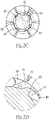
- the screw head 10 as shown in Fig. 1 to Fig. 3B , comprises a top 11 and a neck 12 extending from the top 11 and tapering away from the top 11, the neck 12 being provided with a plurality of ribs 13 which, when locked into a wooden workpiece, enhance the embedability with the wooden workpiece.
- the rod body 20 extends from the neck 12 of the screw head 10 and includes a rod extension part 21 connected to the neck 12, a reaming part 22 connected to the rod extension part 21, and a taper part 23 connected to an other side of the reaming part 22.
- the rod extension part 21 has a first bottom diameter W1
- the reaming part 22 has a second bottom diameter W2, wherein a diameter width of the first bottom diameter W1 of the rod extension part 21 is different from a diameter width of the second bottom diameter W2 of the reaming part 22, and the diameter width of the second bottom diameter W2 is greater than zero and smaller than the diameter width of the first bottom diameter W1.
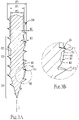
- the first thread 30 is annularly arranged on an outer peripheral surface of the rod body 20 at a distance from the taper part 23 to the rod extension part 21 through the reaming part 22, wherein the first thread 30 has a first height HI at the rod extension part 21, and the first thread 30 has a second height H2 at the reaming part 22.
- the first height HI is different from the second height H2 and the first height HI is greater than zero and less than the second height H2, and the first thread 30 has a first thread outer diameter width W3, and the first thread outer diameter width W3 of the rod extension part 21 and the first thread outer diameter width W3 of the reaming part 22 are the same.
- the first thread outer diameter width W3 at the rod extension part 21 and the first thread outer diameter width W3 at the reaming part 22 are the same.
- the rod body 20 is provided with one first thread 30, and the body 20 may be provided with no less than two first threads 30, without limitation.
- the first thread 30 has a first thread angle ⁇ 1 at the reaming part 22 with the reaming part, and the first thread 30 has a second thread angle ⁇ 2 at the taper 23.
- An angle of the first thread angle ⁇ 1 is different from an angle of the second thread angle ⁇ 2, wherein the first thread angle ⁇ 1 is between about 30 degrees and 50 degrees, the first thread angle ⁇ 1 of the first embodiment being 40 degrees, and the second thread angle ⁇ 2 is between about 40 degrees and 60 degrees, the second thread angle ⁇ 2 of the first embodiment being 50 degrees.
- the first thread 30 has an asymmetric structure.
- the crushing ribs 40 are provided on the outer peripheral surface of the rod body 20 at the reaming part 22.
- the first embodiment has four crushing ribs 40, each of which has a first side surface 41, a second side surface 42 and a ridge portion43 formed at the junction of the first side surface 41 and the second side surface 42.
- Each crushing rib 40 is spirally arranged on the outer peripheral surface of the reaming part 22 of the rod body 20 in a direction C parallel to an axis of the rod body 20, and the cross section of the ridge portion 43 has an arc shape, but is not limited thereto.
- the first thread 30 at the reaming part 32 is provided with a plurality of saw-tooth cutting edges 31 at the outer periphery thereof, and the saw-tooth cutting edges 31 enable the reaming part 22 thereof to easily ream the wood workpiece when locked.
- a first included angle ⁇ 1 is formed between the first side surface 41 of each crushing rib 40 and the outer peripheral surface of the rod body 20 form at the the cross section of the crushing rib 40 and the rod body 20.
- a second included angle ⁇ 2 is formed between the second side surface 42 of each crushing rib 40 and the outer peripheral surface of the rod body 20 at the cross section of the crushing rib 40 and the rod body 20.
- the first included angle ⁇ 1 is different from the second included angle ⁇ 2, and the difference value between the first included angle ⁇ 1 and the second included angle ⁇ 2 is greater than or equal to 5 degrees. and less than or equal to 45 degrees.
- the difference between the first included angle ⁇ 1 and the second included angle ⁇ 2 is approximately 15 degrees, and the angle value of the first included angle ⁇ 1 is greater than the angle value of the second included angle ⁇ 2.
- the angle value of the first included angle ⁇ 1 is between 30 degrees and 80 degrees, while the angle value of the second included angle ⁇ 2 is between 5 and 30 degrees, whereby the generated chips are not easily accumulated at the reaming part 22 and can be quickly discharged and the wear of the first thread 30 is reduced as shown in Fig. 2B .
- Each crushing rib 40 is tapered to the rod body 20 at both ends. with reference to Fig. 4A to Fig.
- FIG. 4B there is shown a second embodiment of the present disclosure, the main features and functions of which are the same as those of the first embodiment, and the main difference is that the second embodiment forms five crushing ribs 40 on the reaming part 22.
- a third included angle ⁇ 3 is formed between the first side surface 41 of each crushing rib 40 and the outer peripheral surface of the first thread 30 at the reaming part 22 of the rod body 20, the third included angle ⁇ 3 being less than 90 degrees and greater than zero degree.
- a user can form two crushing ribs 40, three crushing ribs 40, four crushing ribs 40, five crushing ribs 40, six crushing ribs 40, seven crushing ribs 40, eight crushing ribs 40 and the like on the outer peripheral surface of the reaming part 22 as required, without limitation.
- a user may also provide an oblique thread (not numbered) on the outer peripheral surface of the rod extension part 21 between the first thread 30 and the neck 12 according to his or her needs, without affecting the structure and the resulting efficacy of the crushing rib 40 of the present disclosure. with reference to Fig. 5A to Fig.
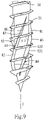
- each crushing rib 40 of the reaming part 21 of the third embodiment is spirally arranged in an axial direction C of the rod body 20 in a counterclockwise direction. That is, the arrangement directions of the crushing ribs 40 and the rotation of the first thread 30 in the axial direction C of the rod body 20 are different, so that the third included angle ⁇ 3 formed by the first side surface 41 of each crushing rib 40 and the outer peripheral surface of the first thread 30 on the reaming part 22 of the rod body 20 is greater than 90 degrees and less than 180 degrees.
- a fourth embodiment of the present disclosure the main features and functions of which are the same as those of the first embodiment and will not be described in detail.
- the main difference is that the ridge portion 43 of each crushing rib 40 of the fourth embodiment is provided with a plurality of peaks 431 and valleys 432 which are alternately arranged, and both ends of each crushing rib 40 are tapered to the rod body 20.
- the ridge portions 43 of each crushing ribs 40 are wavy so as to facilitate crushing and removal of chips generated.
- a fifth embodiment of the present disclosure the main features and functions of which are the same as those of the first embodiment and will not be described in detail.
- the main difference is that the ridge portion 43 of each crushing rib 40 of the fourth embodiment is provided with peaks 431 and valleys 432 which are alternately arranged.
- the height difference between the peaks 431 and the valleys 432 of the fifth embodiment is greater than the height difference between the peaks 431 and the valleys 432 of the fourth embodiment, whereby the ridge portions 43 of each crushing rib 40 are wavy to also facilitate crushing and removal of chips generated.
- a sixth embodiment of the present disclosure the main features and functions of which are the same as those of the first embodiment and will not be described in detail.
- the main difference is that the ridge portion 43 of each crushing rib 40 of the sixth embodiment is provided with a plurality of peaks 431 and valleys 432 which are arranged alternately, and both ends of each crushing rib 40 are tapered to the rod body 20.
- the ridge portion 43 of each crushing rib 40 is wavy to facilitate crushing and removal of chips generated, and the crushing rib 40 extends to the taper part 23 so that generated chips are removed from the taper part 23.
- a seventh embodiment of the present disclosure the main features and functions of which are the same as those of the first embodiment and will not be described in detail.
- the main difference is that the ridge portion 43 of each crushing rib 40 of the seventh embodiment is provided with a plurality of peaks 431 and valleys 432 which are arranged alternately.
- the ridge portion 43 of each crushing rib 40 is wavy so as to facilitate crushing and removal of chips generated, and a quick chip removal groove 50 is formed at the reaming part 22 so that chips generated by the crushing process can be quickly discharged through the quick chip removal groove 50.
- first included angle ⁇ 1 and the second included angle ⁇ 2 of each crushing rib 40 of the low-wear screw structure of the present disclosure are different and the first included angle ⁇ 1 is greater than the second included angle ⁇ 2, so that chips located between the first threads 30 can be easily broken and crushed when a wooden workpiece is locked in.
- the torque force screwed in when the first threads 30 are locked is reduced, so that the abrasion of the first threads 30 can be reduced.
- the first thread 30 is designed such that the first thread outer diameter width W3 of the first thread 30 is the same as that of the rod extension part 21 and the reaming part 22 with the diameter width of the first bottom diameter W1 of the rod extension part 21 being different from the diameter width of the second bottom diameter W2 of the reaming part 22, thereby allowing an operator to lock a wooden workpiece with little effort.
Landscapes
- Engineering & Computer Science (AREA)
- General Engineering & Computer Science (AREA)
- Mechanical Engineering (AREA)
- Life Sciences & Earth Sciences (AREA)
- Chemical & Material Sciences (AREA)
- Dispersion Chemistry (AREA)
- Wood Science & Technology (AREA)
- Physics & Mathematics (AREA)
- Geometry (AREA)
- Food-Manufacturing Devices (AREA)
- Connection Of Plates (AREA)
Priority Applications (2)
| Application Number | Priority Date | Filing Date | Title |
|---|---|---|---|
| PL20197713.9T PL3974664T3 (pl) | 2020-09-23 | 2020-09-23 | Konstrukcja wkręta o małym zużyciu |
| EP20197713.9A EP3974664B8 (de) | 2020-09-23 | 2020-09-23 | Verschleissarme schraubstruktur |
Applications Claiming Priority (1)
| Application Number | Priority Date | Filing Date | Title |
|---|---|---|---|
| EP20197713.9A EP3974664B8 (de) | 2020-09-23 | 2020-09-23 | Verschleissarme schraubstruktur |
Publications (3)
| Publication Number | Publication Date |
|---|---|
| EP3974664A1 true EP3974664A1 (de) | 2022-03-30 |
| EP3974664B1 EP3974664B1 (de) | 2023-11-29 |
| EP3974664B8 EP3974664B8 (de) | 2024-01-24 |
Family
ID=72643980
Family Applications (1)
| Application Number | Title | Priority Date | Filing Date |
|---|---|---|---|
| EP20197713.9A Active EP3974664B8 (de) | 2020-09-23 | 2020-09-23 | Verschleissarme schraubstruktur |
Country Status (2)
| Country | Link |
|---|---|
| EP (1) | EP3974664B8 (de) |
| PL (1) | PL3974664T3 (de) |
Citations (3)
| Publication number | Priority date | Publication date | Assignee | Title |
|---|---|---|---|---|
| US2263137A (en) | 1940-03-02 | 1941-11-18 | Parker Kalon Corp | Fastener device |
| EP0939235A1 (de) * | 1998-02-25 | 1999-09-01 | Ludwig Hettich & Co. | Schraube |
| US20150010374A1 (en) * | 2013-03-26 | 2015-01-08 | Simpson Strong-Tie Company, Inc. | Variable thread fastener |
Family Cites Families (10)
| Publication number | Priority date | Publication date | Assignee | Title |
|---|---|---|---|---|
| ES1070104Y (es) | 2009-03-30 | 2010-02-04 | Tecn Expansivas S L | Tirafondo para madera |
| TW201821704A (zh) | 2016-12-02 | 2018-06-16 | 趙穎慶 | 螺絲結構 |
| DE102017103526A1 (de) * | 2017-02-21 | 2018-08-23 | Fischerwerke Gmbh & Co. Kg | Schraube |
| DE102017108225A1 (de) | 2017-04-18 | 2018-10-18 | Adolf Würth Gmbh & Co Kg | Holzschraube mit bogenförmigem Überstand zwischen Gewindegängen |
| DE102017212439A1 (de) | 2017-07-20 | 2019-01-24 | Swg Schraubenwerk Gaisbach Gmbh | Holzschraube |
| TWM553763U (zh) | 2017-09-21 | 2018-01-01 | Taiwan Shan Yin International Co Ltd | 可快速進給鎖合之螺絲 |
| CN208845543U (zh) | 2018-08-30 | 2019-05-10 | 浙江天开实业有限公司 | 刮削端锯齿螺丝及其搓牙模具 |
| US11137012B2 (en) | 2019-02-21 | 2021-10-05 | Kuo Tai Hsu | Wood screw |
| TWM584843U (zh) | 2019-05-21 | 2019-10-11 | 捷貿興業有限公司 | 可切斷纖維的螺釘 |
| CN211550207U (zh) | 2019-12-31 | 2020-09-22 | 吴江市荣杰五金机械有限公司 | 一种新型螺丝组件 |
-
2020
- 2020-09-23 EP EP20197713.9A patent/EP3974664B8/de active Active
- 2020-09-23 PL PL20197713.9T patent/PL3974664T3/pl unknown
Patent Citations (3)
| Publication number | Priority date | Publication date | Assignee | Title |
|---|---|---|---|---|
| US2263137A (en) | 1940-03-02 | 1941-11-18 | Parker Kalon Corp | Fastener device |
| EP0939235A1 (de) * | 1998-02-25 | 1999-09-01 | Ludwig Hettich & Co. | Schraube |
| US20150010374A1 (en) * | 2013-03-26 | 2015-01-08 | Simpson Strong-Tie Company, Inc. | Variable thread fastener |
Non-Patent Citations (3)
| Title |
|---|
| ANONYMOUS: "LEITFADEN ZUR AUSSENGEWINDEFERTIGUNG Technologie und Rahmenbedingungen", WAGNER TOOLINGSYSTEMS BAUBLIES GMBH, 1 January 2020 (2020-01-01), pages 1 - 32, XP093027607, Retrieved from the Internet <URL:www.baublies-group.com> [retrieved on 20230228] |
| KIRICHEK A. V., AFONIN, A. N.; HIRSCH, A.; KRAUSEL, V.; GUK, A.: "Werkstofffluss beim Gewindewalzen", UMFORMTECHNIK-WHITEPAPER, 1 January 2014 (2014-01-01), pages 1 - 8, XP093027553 |
| WALZL ALEXANDER: "Additive Manufacturing zur Herstellung von Umformwerkzeugen", MASTER THESIS, MONTANUNIVERSITÄT LEOBEN, 1 March 2015 (2015-03-01), pages 1 - 67, XP093027596 |
Also Published As
| Publication number | Publication date |
|---|---|
| PL3974664T3 (pl) | 2024-04-29 |
| EP3974664B8 (de) | 2024-01-24 |
| EP3974664B1 (de) | 2023-11-29 |
Similar Documents
| Publication | Publication Date | Title |
|---|---|---|
| US11598363B2 (en) | Low-wear screw structure | |
| US11149776B2 (en) | Screw structure | |
| CN101058122B (zh) | 用于切屑去除加工的工具以及用于该工具的部件和螺纹接头 | |
| AU2019410833B2 (en) | Screw with milling-ribs for countersinking the screw and use of the screw | |
| US9719545B2 (en) | Screw | |
| IL257313A (en) | Multi-channel front grinder | |
| TWI401368B (zh) | 螺絲 | |
| EP3225858B1 (de) | Schraube | |
| TWI720899B (zh) | 快速排屑擴孔螺絲 | |
| EP3974664A1 (de) | Verschleissarme schraubstruktur | |
| JP6177838B2 (ja) | ねじ | |
| TWM604844U (zh) | 低磨損螺絲結構 | |
| CN204486885U (zh) | 一种新式rk11d铣刀结构 | |
| CN2229320Y (zh) | 钻刀的旋合结构及刀具角度设计与排置 | |
| JP5241557B2 (ja) | セルフタッピングインサート | |
| TWI568939B (zh) | 螺絲 | |
| TWI747144B (zh) | 螺絲 | |
| TWI747473B (zh) | 低磨損螺絲結構 | |
| TWM613314U (zh) | 平頭螺絲之帽頭構造 | |
| TWM511559U (zh) | 螺絲 | |
| TWI734312B (zh) | 具有擴孔部的螺絲 | |
| KR101764539B1 (ko) | 나사절삭용 절삭툴의 절삭팁 | |
| EP3822498B1 (de) | Holzschraubenstruktur | |
| CN113027890A (zh) | 具切槽的尖尾螺丝 | |
| TWI733584B (zh) | 具有切削凸牙的螺絲 |
Legal Events
| Date | Code | Title | Description |
|---|---|---|---|
| PUAI | Public reference made under article 153(3) epc to a published international application that has entered the european phase |
Free format text: ORIGINAL CODE: 0009012 |
|
| STAA | Information on the status of an ep patent application or granted ep patent |
Free format text: STATUS: REQUEST FOR EXAMINATION WAS MADE |
|
| 17P | Request for examination filed |
Effective date: 20220118 |
|
| AK | Designated contracting states |
Kind code of ref document: A1 Designated state(s): AL AT BE BG CH CY CZ DE DK EE ES FI FR GB GR HR HU IE IS IT LI LT LU LV MC MK MT NL NO PL PT RO RS SE SI SK SM TR |
|
| TPAC | Observations filed by third parties |
Free format text: ORIGINAL CODE: EPIDOSNTIPA |
|
| GRAP | Despatch of communication of intention to grant a patent |
Free format text: ORIGINAL CODE: EPIDOSNIGR1 |
|
| STAA | Information on the status of an ep patent application or granted ep patent |
Free format text: STATUS: GRANT OF PATENT IS INTENDED |
|
| INTG | Intention to grant announced |
Effective date: 20230601 |
|
| GRAS | Grant fee paid |
Free format text: ORIGINAL CODE: EPIDOSNIGR3 |
|
| P01 | Opt-out of the competence of the unified patent court (upc) registered |
Effective date: 20230821 |
|
| GRAA | (expected) grant |
Free format text: ORIGINAL CODE: 0009210 |
|
| STAA | Information on the status of an ep patent application or granted ep patent |
Free format text: STATUS: THE PATENT HAS BEEN GRANTED |
|
| AK | Designated contracting states |
Kind code of ref document: B1 Designated state(s): AL AT BE BG CH CY CZ DE DK EE ES FI FR GB GR HR HU IE IS IT LI LT LU LV MC MK MT NL NO PL PT RO RS SE SI SK SM TR |
|
| REG | Reference to a national code |
Ref country code: GB Ref legal event code: FG4D |
|
| REG | Reference to a national code |
Ref country code: CH Ref legal event code: EP |
|
| REG | Reference to a national code |
Ref country code: DE Ref legal event code: R096 Ref document number: 602020021781 Country of ref document: DE |
|
| REG | Reference to a national code |
Ref country code: IE Ref legal event code: FG4D |
|
| REG | Reference to a national code |
Ref country code: CH Ref legal event code: PK Free format text: BERICHTIGUNG B8 |
|
| RAP4 | Party data changed (patent owner data changed or rights of a patent transferred) |
Owner name: BI-MIRTH CORP. |
|
| REG | Reference to a national code |
Ref country code: AT Ref legal event code: UEP Ref document number: 1636409 Country of ref document: AT Kind code of ref document: T Effective date: 20231129 |
|
| REG | Reference to a national code |
Ref country code: LT Ref legal event code: MG9D |
|
| REG | Reference to a national code |
Ref country code: NL Ref legal event code: MP Effective date: 20231129 |
|
| PG25 | Lapsed in a contracting state [announced via postgrant information from national office to epo] |
Ref country code: GR Free format text: LAPSE BECAUSE OF FAILURE TO SUBMIT A TRANSLATION OF THE DESCRIPTION OR TO PAY THE FEE WITHIN THE PRESCRIBED TIME-LIMIT Effective date: 20240301 |
|
| PG25 | Lapsed in a contracting state [announced via postgrant information from national office to epo] |
Ref country code: IS Free format text: LAPSE BECAUSE OF FAILURE TO SUBMIT A TRANSLATION OF THE DESCRIPTION OR TO PAY THE FEE WITHIN THE PRESCRIBED TIME-LIMIT Effective date: 20240329 |
|
| PG25 | Lapsed in a contracting state [announced via postgrant information from national office to epo] |
Ref country code: LT Free format text: LAPSE BECAUSE OF FAILURE TO SUBMIT A TRANSLATION OF THE DESCRIPTION OR TO PAY THE FEE WITHIN THE PRESCRIBED TIME-LIMIT Effective date: 20231129 |
|
| PG25 | Lapsed in a contracting state [announced via postgrant information from national office to epo] |
Ref country code: ES Free format text: LAPSE BECAUSE OF FAILURE TO SUBMIT A TRANSLATION OF THE DESCRIPTION OR TO PAY THE FEE WITHIN THE PRESCRIBED TIME-LIMIT Effective date: 20231129 |
|
| PG25 | Lapsed in a contracting state [announced via postgrant information from national office to epo] |
Ref country code: LT Free format text: LAPSE BECAUSE OF FAILURE TO SUBMIT A TRANSLATION OF THE DESCRIPTION OR TO PAY THE FEE WITHIN THE PRESCRIBED TIME-LIMIT Effective date: 20231129 Ref country code: IS Free format text: LAPSE BECAUSE OF FAILURE TO SUBMIT A TRANSLATION OF THE DESCRIPTION OR TO PAY THE FEE WITHIN THE PRESCRIBED TIME-LIMIT Effective date: 20240329 Ref country code: GR Free format text: LAPSE BECAUSE OF FAILURE TO SUBMIT A TRANSLATION OF THE DESCRIPTION OR TO PAY THE FEE WITHIN THE PRESCRIBED TIME-LIMIT Effective date: 20240301 Ref country code: ES Free format text: LAPSE BECAUSE OF FAILURE TO SUBMIT A TRANSLATION OF THE DESCRIPTION OR TO PAY THE FEE WITHIN THE PRESCRIBED TIME-LIMIT Effective date: 20231129 Ref country code: BG Free format text: LAPSE BECAUSE OF FAILURE TO SUBMIT A TRANSLATION OF THE DESCRIPTION OR TO PAY THE FEE WITHIN THE PRESCRIBED TIME-LIMIT Effective date: 20240229 |
|
| PG25 | Lapsed in a contracting state [announced via postgrant information from national office to epo] |
Ref country code: NL Free format text: LAPSE BECAUSE OF FAILURE TO SUBMIT A TRANSLATION OF THE DESCRIPTION OR TO PAY THE FEE WITHIN THE PRESCRIBED TIME-LIMIT Effective date: 20231129 |
|
| PG25 | Lapsed in a contracting state [announced via postgrant information from national office to epo] |
Ref country code: SE Free format text: LAPSE BECAUSE OF FAILURE TO SUBMIT A TRANSLATION OF THE DESCRIPTION OR TO PAY THE FEE WITHIN THE PRESCRIBED TIME-LIMIT Effective date: 20231129 Ref country code: RS Free format text: LAPSE BECAUSE OF FAILURE TO SUBMIT A TRANSLATION OF THE DESCRIPTION OR TO PAY THE FEE WITHIN THE PRESCRIBED TIME-LIMIT Effective date: 20231129 Ref country code: NO Free format text: LAPSE BECAUSE OF FAILURE TO SUBMIT A TRANSLATION OF THE DESCRIPTION OR TO PAY THE FEE WITHIN THE PRESCRIBED TIME-LIMIT Effective date: 20240229 Ref country code: NL Free format text: LAPSE BECAUSE OF FAILURE TO SUBMIT A TRANSLATION OF THE DESCRIPTION OR TO PAY THE FEE WITHIN THE PRESCRIBED TIME-LIMIT Effective date: 20231129 Ref country code: LV Free format text: LAPSE BECAUSE OF FAILURE TO SUBMIT A TRANSLATION OF THE DESCRIPTION OR TO PAY THE FEE WITHIN THE PRESCRIBED TIME-LIMIT Effective date: 20231129 Ref country code: HR Free format text: LAPSE BECAUSE OF FAILURE TO SUBMIT A TRANSLATION OF THE DESCRIPTION OR TO PAY THE FEE WITHIN THE PRESCRIBED TIME-LIMIT Effective date: 20231129 |
|
| PG25 | Lapsed in a contracting state [announced via postgrant information from national office to epo] |
Ref country code: DK Free format text: LAPSE BECAUSE OF FAILURE TO SUBMIT A TRANSLATION OF THE DESCRIPTION OR TO PAY THE FEE WITHIN THE PRESCRIBED TIME-LIMIT Effective date: 20231129 |
|
| PG25 | Lapsed in a contracting state [announced via postgrant information from national office to epo] |
Ref country code: CZ Free format text: LAPSE BECAUSE OF FAILURE TO SUBMIT A TRANSLATION OF THE DESCRIPTION OR TO PAY THE FEE WITHIN THE PRESCRIBED TIME-LIMIT Effective date: 20231129 |
|
| PG25 | Lapsed in a contracting state [announced via postgrant information from national office to epo] |
Ref country code: SK Free format text: LAPSE BECAUSE OF FAILURE TO SUBMIT A TRANSLATION OF THE DESCRIPTION OR TO PAY THE FEE WITHIN THE PRESCRIBED TIME-LIMIT Effective date: 20231129 |
|
| PG25 | Lapsed in a contracting state [announced via postgrant information from national office to epo] |
Ref country code: SM Free format text: LAPSE BECAUSE OF FAILURE TO SUBMIT A TRANSLATION OF THE DESCRIPTION OR TO PAY THE FEE WITHIN THE PRESCRIBED TIME-LIMIT Effective date: 20231129 Ref country code: SK Free format text: LAPSE BECAUSE OF FAILURE TO SUBMIT A TRANSLATION OF THE DESCRIPTION OR TO PAY THE FEE WITHIN THE PRESCRIBED TIME-LIMIT Effective date: 20231129 Ref country code: RO Free format text: LAPSE BECAUSE OF FAILURE TO SUBMIT A TRANSLATION OF THE DESCRIPTION OR TO PAY THE FEE WITHIN THE PRESCRIBED TIME-LIMIT Effective date: 20231129 Ref country code: EE Free format text: LAPSE BECAUSE OF FAILURE TO SUBMIT A TRANSLATION OF THE DESCRIPTION OR TO PAY THE FEE WITHIN THE PRESCRIBED TIME-LIMIT Effective date: 20231129 Ref country code: DK Free format text: LAPSE BECAUSE OF FAILURE TO SUBMIT A TRANSLATION OF THE DESCRIPTION OR TO PAY THE FEE WITHIN THE PRESCRIBED TIME-LIMIT Effective date: 20231129 Ref country code: CZ Free format text: LAPSE BECAUSE OF FAILURE TO SUBMIT A TRANSLATION OF THE DESCRIPTION OR TO PAY THE FEE WITHIN THE PRESCRIBED TIME-LIMIT Effective date: 20231129 |
|
| PG25 | Lapsed in a contracting state [announced via postgrant information from national office to epo] |
Ref country code: PT Free format text: LAPSE BECAUSE OF FAILURE TO SUBMIT A TRANSLATION OF THE DESCRIPTION OR TO PAY THE FEE WITHIN THE PRESCRIBED TIME-LIMIT Effective date: 20240401 |
|
| REG | Reference to a national code |
Ref country code: DE Ref legal event code: R026 Ref document number: 602020021781 Country of ref document: DE |
|
| PG25 | Lapsed in a contracting state [announced via postgrant information from national office to epo] |
Ref country code: PT Free format text: LAPSE BECAUSE OF FAILURE TO SUBMIT A TRANSLATION OF THE DESCRIPTION OR TO PAY THE FEE WITHIN THE PRESCRIBED TIME-LIMIT Effective date: 20240401 |
|
| PLBI | Opposition filed |
Free format text: ORIGINAL CODE: 0009260 |
|
| PLAB | Opposition data, opponent's data or that of the opponent's representative modified |
Free format text: ORIGINAL CODE: 0009299OPPO |
|
| PLAX | Notice of opposition and request to file observation + time limit sent |
Free format text: ORIGINAL CODE: EPIDOSNOBS2 |
|
| 26 | Opposition filed |
Opponent name: SCHWARZ & PARTNER PATENTANWAELTE GMBH Effective date: 20240827 |
|
| R26 | Opposition filed (corrected) |
Opponent name: SCHWARZ & PARTNER PATENTANWAELTE GMBH Effective date: 20240827 |
|
| PG25 | Lapsed in a contracting state [announced via postgrant information from national office to epo] |
Ref country code: SI Free format text: LAPSE BECAUSE OF FAILURE TO SUBMIT A TRANSLATION OF THE DESCRIPTION OR TO PAY THE FEE WITHIN THE PRESCRIBED TIME-LIMIT Effective date: 20231129 |
|
| PG25 | Lapsed in a contracting state [announced via postgrant information from national office to epo] |
Ref country code: SI Free format text: LAPSE BECAUSE OF FAILURE TO SUBMIT A TRANSLATION OF THE DESCRIPTION OR TO PAY THE FEE WITHIN THE PRESCRIBED TIME-LIMIT Effective date: 20231129 |
|
| PLBB | Reply of patent proprietor to notice(s) of opposition received |
Free format text: ORIGINAL CODE: EPIDOSNOBS3 |
|
| PG25 | Lapsed in a contracting state [announced via postgrant information from national office to epo] |
Ref country code: MC Free format text: LAPSE BECAUSE OF FAILURE TO SUBMIT A TRANSLATION OF THE DESCRIPTION OR TO PAY THE FEE WITHIN THE PRESCRIBED TIME-LIMIT Effective date: 20231129 |
|
| PG25 | Lapsed in a contracting state [announced via postgrant information from national office to epo] |
Ref country code: LU Free format text: LAPSE BECAUSE OF NON-PAYMENT OF DUE FEES Effective date: 20240923 |
|
| GBPC | Gb: european patent ceased through non-payment of renewal fee |
Effective date: 20240923 |
|
| PG25 | Lapsed in a contracting state [announced via postgrant information from national office to epo] |
Ref country code: GB Free format text: LAPSE BECAUSE OF NON-PAYMENT OF DUE FEES Effective date: 20240923 |
|
| REG | Reference to a national code |
Ref country code: BE Ref legal event code: MM Effective date: 20240930 |
|
| PG25 | Lapsed in a contracting state [announced via postgrant information from national office to epo] |
Ref country code: BE Free format text: LAPSE BECAUSE OF NON-PAYMENT OF DUE FEES Effective date: 20240930 |
|
| PG25 | Lapsed in a contracting state [announced via postgrant information from national office to epo] |
Ref country code: IE Free format text: LAPSE BECAUSE OF NON-PAYMENT OF DUE FEES Effective date: 20240923 |
|
| REG | Reference to a national code |
Ref country code: CH Ref legal event code: U11 Free format text: ST27 STATUS EVENT CODE: U-0-0-U10-U11 (AS PROVIDED BY THE NATIONAL OFFICE) Effective date: 20251001 |
|
| PG25 | Lapsed in a contracting state [announced via postgrant information from national office to epo] |
Ref country code: FI Free format text: LAPSE BECAUSE OF FAILURE TO SUBMIT A TRANSLATION OF THE DESCRIPTION OR TO PAY THE FEE WITHIN THE PRESCRIBED TIME-LIMIT Effective date: 20231129 |
|
| PGFP | Annual fee paid to national office [announced via postgrant information from national office to epo] |
Ref country code: PL Payment date: 20250918 Year of fee payment: 6 |
|
| PGFP | Annual fee paid to national office [announced via postgrant information from national office to epo] |
Ref country code: FR Payment date: 20250930 Year of fee payment: 6 Ref country code: AT Payment date: 20250918 Year of fee payment: 6 |
|
| APBP | Date of receipt of notice of appeal recorded |
Free format text: ORIGINAL CODE: EPIDOSNNOA2O |
|
| APAH | Appeal reference modified |
Free format text: ORIGINAL CODE: EPIDOSCREFNO |
|
| PGFP | Annual fee paid to national office [announced via postgrant information from national office to epo] |
Ref country code: DE Payment date: 20250930 Year of fee payment: 6 |
|
| PGFP | Annual fee paid to national office [announced via postgrant information from national office to epo] |
Ref country code: IT Payment date: 20250930 Year of fee payment: 6 |
|
| PGFP | Annual fee paid to national office [announced via postgrant information from national office to epo] |
Ref country code: CH Payment date: 20251001 Year of fee payment: 6 |
|
| PG25 | Lapsed in a contracting state [announced via postgrant information from national office to epo] |
Ref country code: CY Free format text: LAPSE BECAUSE OF FAILURE TO SUBMIT A TRANSLATION OF THE DESCRIPTION OR TO PAY THE FEE WITHIN THE PRESCRIBED TIME-LIMIT; INVALID AB INITIO Effective date: 20200923 |
|
| APBQ | Date of receipt of statement of grounds of appeal recorded |
Free format text: ORIGINAL CODE: EPIDOSNNOA3O |
|
| PG25 | Lapsed in a contracting state [announced via postgrant information from national office to epo] |
Ref country code: HU Free format text: LAPSE BECAUSE OF FAILURE TO SUBMIT A TRANSLATION OF THE DESCRIPTION OR TO PAY THE FEE WITHIN THE PRESCRIBED TIME-LIMIT; INVALID AB INITIO Effective date: 20200923 |