EP3974583B1 - Planierraupe - Google Patents
Planierraupe Download PDFInfo
- Publication number
- EP3974583B1 EP3974583B1 EP21197319.3A EP21197319A EP3974583B1 EP 3974583 B1 EP3974583 B1 EP 3974583B1 EP 21197319 A EP21197319 A EP 21197319A EP 3974583 B1 EP3974583 B1 EP 3974583B1
- Authority
- EP
- European Patent Office
- Prior art keywords
- bulldozer
- blade
- blades
- angle
- troughs
- Prior art date
- Legal status (The legal status is an assumption and is not a legal conclusion. Google has not performed a legal analysis and makes no representation as to the accuracy of the status listed.)
- Active
Links
Images
Classifications
-
- E—FIXED CONSTRUCTIONS
- E02—HYDRAULIC ENGINEERING; FOUNDATIONS; SOIL SHIFTING
- E02F—DREDGING; SOIL-SHIFTING
- E02F3/00—Dredgers; Soil-shifting machines
- E02F3/04—Dredgers; Soil-shifting machines mechanically-driven
- E02F3/76—Graders, bulldozers, or the like with scraper plates or ploughshare-like elements; Levelling scarifying devices
- E02F3/80—Component parts
- E02F3/815—Blades; Levelling or scarifying tools
- E02F3/8155—Blades; Levelling or scarifying tools provided with movable parts, e.g. cutting discs, vibrating teeth or the like
-
- E—FIXED CONSTRUCTIONS
- E02—HYDRAULIC ENGINEERING; FOUNDATIONS; SOIL SHIFTING
- E02F—DREDGING; SOIL-SHIFTING
- E02F3/00—Dredgers; Soil-shifting machines
- E02F3/04—Dredgers; Soil-shifting machines mechanically-driven
- E02F3/76—Graders, bulldozers, or the like with scraper plates or ploughshare-like elements; Levelling scarifying devices
- E02F3/80—Component parts
- E02F3/84—Drives or control devices therefor, e.g. hydraulic drive systems
- E02F3/844—Drives or control devices therefor, e.g. hydraulic drive systems for positioning the blade, e.g. hydraulically
-
- E—FIXED CONSTRUCTIONS
- E02—HYDRAULIC ENGINEERING; FOUNDATIONS; SOIL SHIFTING
- E02F—DREDGING; SOIL-SHIFTING
- E02F9/00—Component parts of dredgers or soil-shifting machines, not restricted to one of the kinds covered by groups E02F3/00 - E02F7/00
- E02F9/08—Superstructures; Supports for superstructures
- E02F9/0841—Articulated frame, i.e. having at least one pivot point between two travelling gear units
Definitions
- This invention relates to a bulldozer that is intended for spreading and levelling road surface material over which an asphalt layer is further intended to be applied, which bulldozer is formed of a frame that is articulated in the middle and of bearing chain track wheels and a front bulldozer blade.
- road graders having a long frame, front wheels and rear wheels, and wherein the grader blade is located behind the front wheels.
- the frame is not articulated. This road grader works if the road is long and straight with no bends.
- the wheels of the road grader easily break a levelled and graded road surface. No evenly bearing track wheels are provided.
- the object of this invention is to remedy the defects described above.
- the bulldozer according to the invention is characterized by the features of the appended claim 1.
- One embodiment of the invention is characterized in that the side blades are foldable by hydraulic cylinders that are known per se.
- Another embodiment of the invention is characterized in that the bulldozer blade has two troughs in cross-section, wherein the troughs are longitudinally one on top of the other.
- the bulldozer is intended for spreading and levelling road surface material.
- An asphalt layer is further intended to be applied over the levelled surface.
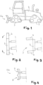
- the bulldozer is formed of a frame 1, 2 that is articulated in the middle and of bearing chain track wheels 3 and a front bulldozer blade 4a, 4b.
- the bulldozer blade has three parts, a body blade 5 and side blades 6 folding forward substantially to an angle of 90° on both sides, whereby a U-shaped trough 7 is formed in front of the bulldozer.
- the side blades 6 are foldable by hydraulic cylinders that are known per se. Not illustrated in the drawing.
- the bulldozer blade 4b has two troughs in cross-section, wherein the troughs 8, 9 are longitudinally one on top of the other.
- the frame of the bulldozer is divided into two parts, a front part 1 and a rear part 2, attached to each other in an articulated manner.
- the articulation is arranged in the vertical direction, whereby the front part and the rear part may pivot relative to each other in the horizontal plane. This enables nimbler operation of the device because due to the articulation, the device can be turned even in a narrow place. At the same time, the precision of work is improved and the device may also be easily used at winding and narrow work sites.
- the device comprises bearing chain track wheels 3 by means of which the weight of the device can be distributed over a larger area than by using traditional wheels, whereby the device leaves less marks on the working surface, or does not leave any marks at all.
- Two of the chain track wheels may be arranged in the front part on opposite sides thereof and two may be arranged in the rear part on opposite sides thereof.
- the device may also comprise more of the chain track wheels in the front part and/or the rear part on different sides thereof.
- the chain track wheel may have a triangular design, when the chain track wheel is viewed from the side.
- the chain track wheel comprises three track wheels that are arranged so that two of the track wheels are arranged so to speak facing the ground, and one is arranged over these two track wheels in the middle, as is illustrated in Fig. 1 .
- the track of the track wheel is arranged to run around the track wheels.
- the bulldozer blade of the device is fixedly attached to the front part of the frame, such that the position of the bulldozer blade may be changed.
- the bulldozer blade may be tilted as desired forward and backward, or it may be turned in the horizontal plane, whereby the material being worked may be guided to the side with the bulldozer blade.
- the bulldozer blade may be attached to the front part of the frame for example with hydraulic cylinders by means of which the position of the bulldozer blade may be changed.
- the front part of the bulldozer may comprise a cab in which the control devices of the device are arranged.
- the control devices may comprise means required to control the device, such as a steering wheel and control means for moving the device forward and backward.
- the cab may comprise bulldozer blade control means for changing its position.
- the bulldozer blade must be fixedly attached, because the material being levelled, such as stones, gravel etc., is very heavy and the bulldozer blade must withstand the forces exerted by the material without the bulldozer blade starting to move by the effect of the forces applied thereto.
- fixed attachment it is meant that the bulldozer blade is rigidly attached to the front part of the bulldozer, whereby the bulldozer blade is supported by the whole weight of the device.
- the bulldozer blade 4a, 4b may be attached to the front part 1 fully or partly hydraulically, e.g. by hydraulic cylinders, whereby the position of the bulldozer blade may be changed hydraulically.
- the bulldozer blade comprises a body blade 5 and side blades 6 arranged at both ends of the body blade 5.
- the angle of the side blades 6 in relation to the body blade 5 may be adjusted in the horizontal plane between 90-180 degrees.
- the side blades 6 are at an angle of 180 degrees relative to the body blade 5 and in Fig. 3 the side blades are at an angle of 90 degrees relative to the body blade 5.
- the angle of each side blade 6 may be adjusted independently, irrespective of the angle of the other side blade, or the angle of the side blades may be adjusted synchronously.
- a bar that is fitted with a camera for imaging the road surface or other material being moved may be attached to the upper part of the body blade of the bulldozer blade.
- the cab of the device may comprise a display to which the signal of the camera may be transmitted and the driver or user of the device sees in real time what is happening in front of the bulldozer blade.
- the driver is able to react quickly if something appears in front of the bulldozer blade that should not be there, or is able to control the device in places that require precision.
- the upper part of the body blade 5 may also comprise two transmitters by means of which the position of the bulldozer blade may be determined.
- the transmitters are arranged at the ends of the upper part of the body blade so that one transmitter is close to a first side part and another transmitter is close to a second side part. Thus the exact position of the blade can be detected.
- the detection of the position may be based on GPS (Global Positioning System).
- the device may also comprise more transmitters.
- Two masts may be attached to the body blade 5 such that the masts are attached to the upper edge of the body blade close to the point of attachment of the side parts, whereby they extend vertically upwards from the surface being worked.
- the transmitters can be attached to these masts.
- the body blade 5 and the side blades 6 each comprise a cutting edge part that is arranged to the lower edge of the blades, extending vertically towards the surface being levelled, i.e. during work the cutting edge is oriented at an angle of approximately 90 degrees relative to the surface being worked.
- This has the advantage that the bulldozer blade is not lifting, i.e. it does not peel material off the surface being worked, but only levels it to a desired level.
- the cutting edge part may be manufactured from a different material than the other parts of the bulldozer blade.
- the cutting edge part may be removably attached to the blades, whereby the cutting edge parts may be replaced as they wear down.
- the bulldozer blade may have two troughs in cross-section, i.e. cross-section as viewed from the side, wherein the troughs 8, 9 are longitudinally, i.e. in the vertical direction, one on top of the other above the cutting edge part.
- the material being levelled/moved does not uncontrollably accumulate in front of the bulldozer blade, but can be spread evenly along the whole width of the bulldozer blade. This way the material being levelled can also be better compacted.
Landscapes
- Engineering & Computer Science (AREA)
- Mining & Mineral Resources (AREA)
- Civil Engineering (AREA)
- General Engineering & Computer Science (AREA)
- Structural Engineering (AREA)
- Mechanical Engineering (AREA)
- Operation Control Of Excavators (AREA)
- Road Paving Machines (AREA)
Claims (12)
- Planierraupe zum Verteilen und Nivellieren von Straßenoberflächenmaterial, auf das ferner eine Asphaltschicht aufgebracht werden soll, wobei die Planierraupe aus einem Rahmen (1, 2), der in der Mitte gelenkig ist, und aus tragenden Ketten-Spurrädern (3) und einem vorderen Planierraupenschild (4a, 4b) gebildet ist, dadurch gekennzeichnet, dass der Planierraupenschild (4a, 4b) drei Teile aufweist, einen Körperschild (5) und Seitenschilde (6), die an beiden Seiten um einen Winkel von 90° nach vorne klappbar sind, wodurch eine U-förmige Mulde (7) vor der Planierraupe gebildet wird, wobei der Körperschild (5) und die Seitenschilde (6) jeweils einen Schneidkantenteil umfassen, der an unteren Kanten der Schilde eingerichtet ist, und im Betrieb die Schneidkante sich vertikal in Richtung der zu nivellierenden Oberfläche in einem Winkel von 90 Grad relativ zur bearbeiteten Oberfläche erstreckt.
- Planierraupe gemäß Anspruch 1, dadurch gekennzeichnet, dass die Seitenschilde (6) durch per se bekannte Hydraulikzylinder klappbar sind.
- Planierraupe gemäß Anspruch 1 oder 2, dadurch gekennzeichnet, dass der Planierraupenschild (4b) im Querschnitt zwei Mulden aufweist, wobei die Mulden (8, 9) in Längsrichtung und eine über der anderen angeordnet sind.
- Planierraupe gemäß Anspruch 1, wobei der Rahmen (1, 2) einen vorderen Teil und einen hinteren Teil umfasst, die in einer gelenkigen Weise aneinander angebracht sind.
- Planierraupe gemäß Anspruch 4, wobei der vordere Teil des Rahmens zwei Ketten-Spurräder umfasst, die an gegenüberliegenden Seiten des vorderen Teils eingerichtet sind, und der hintere Teil des Rahmens zwei Ketten-Spurräder umfasst, die an gegenüberliegenden Seiten des hinteren Teils eingerichtet sind.
- Planierraupe gemäß Anspruch 4 oder 5, wobei der Planierraupenschild (4, 4a) an dem vorderen Teil des Rahmens fest angebracht ist, so dass die Position des Planierraupenschildes von dem Führerhaus aus verändert werden kann.
- Planierraupe gemäß einem der Ansprüche 1-6, wobei der Winkel der Seitenschilde in Bezug auf den Körperschild zwischen 90 und 180 Grad verstellt werden kann.
- Planierraupe gemäß einem der Ansprüche 1-7, wobei der Winkel jedes Seitenschildes unabhängig verstellt werden kann, ungeachtet des Winkels des anderen Seitenschildes.
- Planierraupe gemäß einem der Ansprüche 1-8, wobei eine Stange, die mit einer Kamera zum Abbilden des Straßenoberflächenmaterials ausgestattet ist, am oberen Teil des Körperschildes (5) angebracht ist.
- Planierraupe gemäß einem der Ansprüche 1-9, wobei der obere Teil des Körperschildes (5) zwei Sender umfasst, mit denen die Position des Planierraupenschildes bestimmt werden kann und von denen ein Sender nahe dem Anbringungspunkt eines ersten Seitenschildes und ein anderer Sender nahe dem Anbringungspunkt eines zweiten Seitenschildes positioniert ist.
- Planierraupe gemäß einem der Ansprüche 1-10, wobei der Körperschild (5) und die Seitenschilde (6) jeweils einen Schneidkantenteil umfassen, der an der unteren Kante der Schilde eingerichtet ist und sich vertikal in Richtung der zu nivellierenden Oberfläche erstreckt.
- Planierraupe gemäß einem der Ansprüche 1-11, wobei der Planierraupenschild (4b) im Querschnitt zwei Mulden aufweist, wobei die Mulden (8, 9) in vertikaler Richtung eine über der anderen über dem Schneidkantenteil angeordnet sind.
Applications Claiming Priority (1)
| Application Number | Priority Date | Filing Date | Title |
|---|---|---|---|
| FIU20200099U FI12809Y1 (fi) | 2020-09-24 | 2020-09-24 | Puskuhöylä |
Publications (3)
| Publication Number | Publication Date |
|---|---|
| EP3974583A1 EP3974583A1 (de) | 2022-03-30 |
| EP3974583C0 EP3974583C0 (de) | 2025-06-11 |
| EP3974583B1 true EP3974583B1 (de) | 2025-06-11 |
Family
ID=73135877
Family Applications (1)
| Application Number | Title | Priority Date | Filing Date |
|---|---|---|---|
| EP21197319.3A Active EP3974583B1 (de) | 2020-09-24 | 2021-09-17 | Planierraupe |
Country Status (2)
| Country | Link |
|---|---|
| EP (1) | EP3974583B1 (de) |
| FI (1) | FI12809Y1 (de) |
Family Cites Families (5)
| Publication number | Priority date | Publication date | Assignee | Title |
|---|---|---|---|---|
| JP4082646B2 (ja) * | 1999-11-19 | 2008-04-30 | 株式会社小松製作所 | 排土板の前方監視装置付き車両 |
| US7481011B2 (en) * | 2004-03-30 | 2009-01-27 | Nth Inc. | Double wing scraper |
| US7581598B2 (en) * | 2004-11-29 | 2009-09-01 | Deere & Company | Blade motion reduction |
| US8061063B2 (en) * | 2008-06-17 | 2011-11-22 | Sno-Way International, Inc. | Plow wing blade |
| CN205617458U (zh) * | 2016-03-15 | 2016-10-05 | 徐工集团工程机械有限公司 | 平地机刀片、平地机及推土机 |
-
2020
- 2020-09-24 FI FIU20200099U patent/FI12809Y1/fi active IP Right Grant
-
2021
- 2021-09-17 EP EP21197319.3A patent/EP3974583B1/de active Active
Also Published As
| Publication number | Publication date |
|---|---|
| EP3974583A1 (de) | 2022-03-30 |
| EP3974583C0 (de) | 2025-06-11 |
| FI12809Y1 (fi) | 2020-10-23 |
Similar Documents
| Publication | Publication Date | Title |
|---|---|---|
| US8141650B2 (en) | Automatic depth correction based on blade pitch | |
| CA1134135A (en) | Combination plough | |
| US1997001A (en) | Bulldozer | |
| US6308785B1 (en) | Adjustable grader-spreader bar | |
| US20230122412A1 (en) | Ground working accessories with side shifting option | |
| US5407014A (en) | Gravel scarifying device | |
| CA3093688C (en) | Earth moving implement with adjustable configuration earth moving blades | |
| US11913191B2 (en) | Floating earth levelling blade assembly with shoes | |
| EP2154294A1 (de) | Verlängerbares Räumschild | |
| AU2022202151B2 (en) | Ground contouring apparatus with lateral control | |
| EP3974583B1 (de) | Planierraupe | |
| US6293354B1 (en) | Disc unit | |
| US20070137872A1 (en) | Attachment for road grader blade for grading shoulders | |
| US7096971B1 (en) | Bi-directional drag grader | |
| EP2966226B1 (de) | An baumaschine angeordneter ausleger für anbaugeräte | |
| US20200131727A1 (en) | Convertible snow plow | |
| US3428133A (en) | Land leveler | |
| WO2016013967A1 (en) | Wing attachment for vehicles | |
| FI74090C (fi) | Snoeplog. | |
| US20060070754A1 (en) | Steerable attachment for equipment | |
| CN112602388B (zh) | 使用平地铲门的作业车辆物料管理 | |
| NL2026288B1 (en) | Attachment for a tractor, in particular a leveling planer | |
| CA2255189C (en) | Disc unit | |
| US20070209240A1 (en) | Scraper attachment for skid steer vehicle | |
| AU768356B2 (en) | Grader device |
Legal Events
| Date | Code | Title | Description |
|---|---|---|---|
| PUAI | Public reference made under article 153(3) epc to a published international application that has entered the european phase |
Free format text: ORIGINAL CODE: 0009012 |
|
| STAA | Information on the status of an ep patent application or granted ep patent |
Free format text: STATUS: THE APPLICATION HAS BEEN PUBLISHED |
|
| AK | Designated contracting states |
Kind code of ref document: A1 Designated state(s): AL AT BE BG CH CY CZ DE DK EE ES FI FR GB GR HR HU IE IS IT LI LT LU LV MC MK MT NL NO PL PT RO RS SE SI SK SM TR |
|
| STAA | Information on the status of an ep patent application or granted ep patent |
Free format text: STATUS: REQUEST FOR EXAMINATION WAS MADE |
|
| 17P | Request for examination filed |
Effective date: 20220929 |
|
| RBV | Designated contracting states (corrected) |
Designated state(s): AL AT BE BG CH CY CZ DE DK EE ES FI FR GB GR HR HU IE IS IT LI LT LU LV MC MK MT NL NO PL PT RO RS SE SI SK SM TR |
|
| GRAP | Despatch of communication of intention to grant a patent |
Free format text: ORIGINAL CODE: EPIDOSNIGR1 |
|
| STAA | Information on the status of an ep patent application or granted ep patent |
Free format text: STATUS: GRANT OF PATENT IS INTENDED |
|
| RIC1 | Information provided on ipc code assigned before grant |
Ipc: E02F 3/815 20060101AFI20250130BHEP |
|
| INTG | Intention to grant announced |
Effective date: 20250206 |
|
| GRAS | Grant fee paid |
Free format text: ORIGINAL CODE: EPIDOSNIGR3 |
|
| GRAA | (expected) grant |
Free format text: ORIGINAL CODE: 0009210 |
|
| STAA | Information on the status of an ep patent application or granted ep patent |
Free format text: STATUS: THE PATENT HAS BEEN GRANTED |
|
| AK | Designated contracting states |
Kind code of ref document: B1 Designated state(s): AL AT BE BG CH CY CZ DE DK EE ES FI FR GB GR HR HU IE IS IT LI LT LU LV MC MK MT NL NO PL PT RO RS SE SI SK SM TR |
|
| REG | Reference to a national code |
Ref country code: GB Ref legal event code: FG4D |
|
| REG | Reference to a national code |
Ref country code: CH Ref legal event code: EP |
|
| REG | Reference to a national code |
Ref country code: IE Ref legal event code: FG4D |
|
| REG | Reference to a national code |
Ref country code: DE Ref legal event code: R096 Ref document number: 602021032030 Country of ref document: DE |
|
| U01 | Request for unitary effect filed |
Effective date: 20250627 |
|
| U07 | Unitary effect registered |
Designated state(s): AT BE BG DE DK EE FI FR IT LT LU LV MT NL PT RO SE SI Effective date: 20250703 |
|
| PG25 | Lapsed in a contracting state [announced via postgrant information from national office to epo] |
Ref country code: ES Free format text: LAPSE BECAUSE OF FAILURE TO SUBMIT A TRANSLATION OF THE DESCRIPTION OR TO PAY THE FEE WITHIN THE PRESCRIBED TIME-LIMIT Effective date: 20250611 |
|
| PG25 | Lapsed in a contracting state [announced via postgrant information from national office to epo] |
Ref country code: GR Free format text: LAPSE BECAUSE OF FAILURE TO SUBMIT A TRANSLATION OF THE DESCRIPTION OR TO PAY THE FEE WITHIN THE PRESCRIBED TIME-LIMIT Effective date: 20250912 Ref country code: NO Free format text: LAPSE BECAUSE OF FAILURE TO SUBMIT A TRANSLATION OF THE DESCRIPTION OR TO PAY THE FEE WITHIN THE PRESCRIBED TIME-LIMIT Effective date: 20250911 |
|
| PG25 | Lapsed in a contracting state [announced via postgrant information from national office to epo] |
Ref country code: HR Free format text: LAPSE BECAUSE OF FAILURE TO SUBMIT A TRANSLATION OF THE DESCRIPTION OR TO PAY THE FEE WITHIN THE PRESCRIBED TIME-LIMIT Effective date: 20250611 |
|
| PG25 | Lapsed in a contracting state [announced via postgrant information from national office to epo] |
Ref country code: RS Free format text: LAPSE BECAUSE OF FAILURE TO SUBMIT A TRANSLATION OF THE DESCRIPTION OR TO PAY THE FEE WITHIN THE PRESCRIBED TIME-LIMIT Effective date: 20250911 |
|
| U20 | Renewal fee for the european patent with unitary effect paid |
Year of fee payment: 5 Effective date: 20250916 |