EP3974282B1 - Air conditioner for railway vehicle - Google Patents
Air conditioner for railway vehicle Download PDFInfo
- Publication number
- EP3974282B1 EP3974282B1 EP21199119.5A EP21199119A EP3974282B1 EP 3974282 B1 EP3974282 B1 EP 3974282B1 EP 21199119 A EP21199119 A EP 21199119A EP 3974282 B1 EP3974282 B1 EP 3974282B1
- Authority
- EP
- European Patent Office
- Prior art keywords
- side seal
- seal bearing
- indoor unit
- chamber
- chamber side
- Prior art date
- Legal status (The legal status is an assumption and is not a legal conclusion. Google has not performed a legal analysis and makes no representation as to the accuracy of the status listed.)
- Active
Links
Images


Classifications
-
- B—PERFORMING OPERATIONS; TRANSPORTING
- B61—RAILWAYS
- B61D—BODY DETAILS OR KINDS OF RAILWAY VEHICLES
- B61D27/00—Heating, cooling, ventilating, or air-conditioning
- B61D27/0018—Air-conditioning means, i.e. combining at least two of the following ways of treating or supplying air, namely heating, cooling or ventilating
-
- Y—GENERAL TAGGING OF NEW TECHNOLOGICAL DEVELOPMENTS; GENERAL TAGGING OF CROSS-SECTIONAL TECHNOLOGIES SPANNING OVER SEVERAL SECTIONS OF THE IPC; TECHNICAL SUBJECTS COVERED BY FORMER USPC CROSS-REFERENCE ART COLLECTIONS [XRACs] AND DIGESTS
- Y02—TECHNOLOGIES OR APPLICATIONS FOR MITIGATION OR ADAPTATION AGAINST CLIMATE CHANGE
- Y02T—CLIMATE CHANGE MITIGATION TECHNOLOGIES RELATED TO TRANSPORTATION
- Y02T30/00—Transportation of goods or passengers via railways, e.g. energy recovery or reducing air resistance
Definitions
- the present invention relates to an air conditioner for a railway vehicle.
- an air conditioner for a railroad vehicle (hereinafter referred to as an air conditioner) that adjusts a temperature and humidity environment inside the railroad vehicle is mounted on a roof of the vehicle.
- a housing of an air conditioner incorporated with a refrigeration cycle is partitioned into an indoor unit chamber that mainly accommodates an indoor heat exchanger and an indoor fan, and an outdoor unit chamber that mainly accommodates an outdoor heat exchanger and an outdoor fan.
- the outdoor unit chamber includes a device chamber provided with a compressor or the like.
- JP-A-2018-131037 discloses a technique relating to a housing of an air conditioner for a railroad vehicle provided on a roof of a railroad vehicle.
- the housing of the air conditioner provided for the railroad vehicle includes the indoor unit chamber that mainly accommodates the indoor heat exchanger and the indoor fan, the outdoor unit chamber that mainly accommodates the outdoor heat exchanger and the outdoor fan, and a partition plate that partitions the indoor unit chamber and the outdoor unit chamber.
- a suction port located on an upstream side of the indoor fan provided in the indoor unit chamber is opened to the inside of the indoor unit chamber in order to attract air from the inside of the railroad vehicle to the inside of the indoor unit chamber.
- the air inside the vehicle sucked by the indoor fan is discharged toward the indoor heat exchanger, which is provided in a flow path on a downstream side of the indoor fan, and in a process of passing through the indoor heat exchanger, the heat in the vehicle is transferred to a refrigerant circulating in the refrigeration cycle including the indoor heat exchanger, whereby conditioned air whose temperature and humidity are harmonized is obtained and re-supplied to the inside of the vehicle.
- a pressure in the indoor unit chamber provided with the indoor fan is a negative pressure (equal to or lower than atmospheric pressure) in order to attract the air inside the vehicle by the indoor fan.
- a pressure acts on the partition plate that partitions the indoor unit chamber and the outdoor unit chamber from a side of the outdoor unit chamber to a side of the indoor unit chamber.
- EP 3385587 A proposes an elastic body for closure, an air conditioning device, and a closure method.
- An object of the invention is to provide an air conditioner for a railway vehicle having a configuration in which a wiring penetrating through a partition plate can be reliably sealed with a small number of manufacturing steps.
- the present invention provides one representative air conditioner for a railway vehicle according to claim 1.
- an air conditioner for a railway vehicle having a configuration in which a wiring penetrating through a partition plate can be reliably sealed with a small number of manufacturing steps.
- a railway vehicle is a generic term for vehicles that are operated along a laid track, and means a railroad vehicle, a road surface train, a new traffic system vehicle, a monorail vehicle, or the like.
- an embodiment of the invention will be described as an example of the railroad vehicle as a representative example of the railway vehicle with reference to the drawings.
- a longitudinal direction or a rail direction of an air conditioner housing is referred to as an x direction
- a width direction or a sleeper direction of the air conditioner housing is referred to as a y direction
- a vertical direction or a height direction of the air conditioner housing is referred to as a z direction.
- the directions may be simply referred to as the x direction, the y direction, and the z direction.
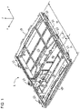
- FIG. 1 is a perspective view of an entire air conditioner housing according to the present embodiment.
- An air conditioner housing 1 is a substantially rectangular parallelepiped having a dimension in the z direction that is smaller than a dimension in the x direction and a dimension in the y direction, and includes an indoor unit chamber A provided with an indoor fan (not shown) and an indoor heat exchanger (not shown), and an outdoor unit chamber B provided with an outdoor fan (not shown) and an outdoor heat exchanger (not shown) along the x direction.
- the outdoor unit chamber B may include a device chamber C provided with a compressor (not shown), an accumulator (not shown), or the like. When no device chamber C is present, the entire outdoor unit chamber B is treated as the device chamber.
- the air conditioner housing 1 includes a bottom plate 10 that is common to the indoor unit chamber A and the outdoor unit chamber B, side plates 20 that are erected at both end portions of the bottom plate 10 in the y direction, end plates 30 that are erected at both end portions of the bottom plate 10 in the x direction, and an upper surface plate (not shown) that is placed on upper ends of the side plates 20 and the end plates 30.
- the indoor unit room A is partitioned by a partition plate 40 from the device chamber (for example, the outdoor unit chamber B or the device chamber C) adjacent to the indoor unit chamber A.
- the bottom plate 10, the side plates 20, and the end plates 30 each include a reinforcing member for increasing rigidity.
- Each side plate 20 is provided with attachment legs 22 provided discretely along the x direction for fixing the air conditioner housing 1 to the roof of the railroad vehicle.
- FIG. 2 is a perspective view of the partition plate through which a wiring penetrates on a side of the indoor unit chamber A.
- FIG. 3 is a perspective view of the partition plate through which the wiring penetrates on a side of the device chamber C adjacent to the indoor unit chamber A.
- An indoor unit chamber side seal bearing unit 44 is provided on the side of the indoor unit chamber A of the partition plate 40, and a device chamber side seal bearing unit 46 is provided on the side of the device chamber (the outdoor unit chamber B or the device chamber C) adjacent to the indoor unit chamber A of the partition plate 40.
- the indoor unit chamber side seal bearing unit 44 includes a pair of end plates 44a and a curved plate 44b bridged over the pair of end plates 44a, and has a form of opening (upper part) in the z direction.
- An outer shape (contour shape projected onto an x-z plane) of each end plate 44a viewed in the y direction (a direction in which the pair of end plates 44a overlap each other) is a substantially trapezoidal shape including a perpendicular portion 44a1 that abuts on the partition plate 40, a curved portion 44a2 that extends from a lower end portion of the perpendicular portion 44a1 to a negative side in the x direction (normal direction of the partition plate 40) and a positive side in the z direction while drawing an arc, and a horizontal portion 44a3 that connects an upper end portion of the curved portion 44a2 and an upper end portion of the perpendicular portion 44a1 substantially horizontally.
- the device chamber side seal bearing unit 46 includes a pair of end plates 46a and a curved plate 46b bridged over the pair of end plates 46a, similarly to the form of the indoor unit chamber side seal bearing unit 44.
- the outer shape of the end plate 46a includes a perpendicular portion 46a1, a curved portion 46a2, and a horizontal portion 46a3.
- an upper edge 46p of the device chamber side seal bearing unit 46 is set to be lower by a dimension G in the z direction than an upper edge 44p of the indoor unit chamber side seal bearing unit 44 in the z direction.
- the indoor unit chamber side seal bearing unit 44 and the device chamber side seal bearing unit 46 are provided in a form of covering a hole 42 and facing each other via the partition plate 40.
- the hole 42 is provided in the partition plate 40 and is penetrated by a wiring 70 from both sides of the partition plate 40.
- the horizontal portions 44a3 and 46a3, which form the upper edges of the indoor unit chamber side seal bearing portion 44 and the device chamber side seal bearing portion 46, respectively, are provided at positions higher than the hole 42 in the z direction, and the indoor unit chamber side seal bearing portion 44 and the device chamber side seal bearing portion 46 are fixed to the both sides of the partition plate 40 in the form of covering the hole 42.
- an accommodating unit that has an opened upper part and is capable of storing a sealing material is formed by the indoor unit chamber side seal bearing unit 44 and the device chamber side seal bearing unit 46, and a center of the accommodating unit is partitioned by the partition plate 40.
- Electric wire supports 60 (see FIGS. 2 and 3 ) extending in the z direction are provided on the partition plate 40 on an upper side (z direction) of the indoor unit chamber side seal bearing unit 44 and the device chamber side seal bearing unit 46.
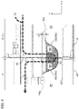
- FIG. 4 is a cross-sectional view of the partition plate penetrated by the wiring.
- a path of the wiring 70 that supplies the electric power to an electric motor of the indoor fan provided in the indoor unit chamber A from a side of the device chamber C (for example, the outdoor unit chamber B or the device chamber C) adjacent to the indoor unit chamber A will be described.
- the wiring 70 extending horizontally from the outdoor unit chamber B (the device chamber C) toward the indoor unit chamber A hangs down to the negative side in the z direction along the electric wire supports 60 provided on the side of the outdoor unit chamber B (the device chamber C) of the partition plate 40 as shown by an alternate long and short dash line, passes through the hole 42 provided in the partition plate 40, bends, and extends toward the side of the indoor unit chamber A.
- the curved plate 46b serves as a guide, and a tip of the wiring 70 is forced to face the hole 42.
- the wiring 70 extending to the side of indoor unit chamber A rises onto the electric wire supports 60 on the positive side in the z direction, extends along the electric wire supports 60, and then extends horizontally and is connected to a terminal block of the indoor fan (not shown) provided in the indoor unit chamber A.
- the tip end of the wiring 70 is forced to face the upper side in the z direction.
- the wiring 70 can be easily provided from the side of the device chamber C to the side of the indoor unit chamber A through the hole 42.
- a sealing material 80 which is a filler, is poured into the indoor unit chamber side seal bearing unit 44 and the device chamber side seal bearing unit 46, and is cured.
- the sealing material 80 poured into the indoor unit chamber side seal bearing portion 44 and the device chamber side seal bearing portion 46 fills a gap between bundles of the wiring 70 and a peripheral portion of the wiring 70 penetrating the hole 42 of the partition plate 40 without gaps, the periphery of the wiring 70 penetrating the partition plate 40 can be firmly sealed (airtight and watertight treatment) . Further, since the sealing material 80 poured into the accommodating unit formed by the indoor unit chamber side seal bearing unit 44 and the device chamber side seal bearing unit 46 is maintained in a stable state, an operator who performs manufacturing work of the air conditioner can be engaged with other operations without particularly paying attention until the sealing material 80 is cured.
- the wiring 70 penetrating the partition plate 40 can be more reliably sealed without requiring a large number of steps. Therefore, it is possible to provide the air conditioner for a railroad vehicle having a configuration in which the wiring 70 penetrating the partition plate 40 can be reliably sealed with a small number of manufacturing steps.
- the upper edge (upper end portion) 44p in the z direction of the indoor unit chamber side seal bearing unit 44 provided on the side of the indoor unit chamber A maintained at the negative pressure is set to be higher by the dimension G in the z direction than the upper edge (upper end portion) 46p of the device chamber side seal bearing unit 46 provided on the side of the device chamber (for example, the outdoor unit chamber B, the device chamber C, or the like) maintained at the atmospheric pressure.
- the dimension G is determined with reference to a specification point static pressure at a rated flow rate of the indoor fan. For example, assuming that the specification point static pressure of the fan is 200 Pa (Pascal, about 20 mm Aq, equivalent to a height of a water column 20 mm), the dimension G is set to a dimension about 25 mm with a slight margin at 20 mm.
- the upper edge 44p of the indoor unit chamber side seal bearing portion 44 is located 25 mm (dimension G) high in the z direction from the upper surface of the sealing material 80 of the indoor unit chamber side seal bearing portion 44, infiltrated water can only infiltrate from an upper surface of the sealing material 80 to the position 20 mm (specification point static pressure of the indoor fan) in the z direction.
- the partition plate 40 may be press-processed to form the indoor unit chamber side seal bearing portion 44 or the device chamber side seal bearing portion 46 integrated with the partition plate 40, and only the indoor unit chamber side seal bearing portion 44 or the device chamber side seal bearing portion 46 not integrally formed with the partition plate 40 may be prepared as a separate member to join to the partition plate 40.
Landscapes
- Engineering & Computer Science (AREA)
- Mechanical Engineering (AREA)
- Air-Conditioning For Vehicles (AREA)
Description
- The present invention relates to an air conditioner for a railway vehicle.
- In the related art, in a railroad vehicle such as a commuter train, except for a part of pendulum type limited express railroad vehicles or the like, an air conditioner for a railroad vehicle (hereinafter referred to as an air conditioner) that adjusts a temperature and humidity environment inside the railroad vehicle is mounted on a roof of the vehicle.
- A housing of an air conditioner incorporated with a refrigeration cycle is partitioned into an indoor unit chamber that mainly accommodates an indoor heat exchanger and an indoor fan, and an outdoor unit chamber that mainly accommodates an outdoor heat exchanger and an outdoor fan. The outdoor unit chamber includes a device chamber provided with a compressor or the like.
JP-A-2018-131037 - As described above, the housing of the air conditioner provided for the railroad vehicle includes the indoor unit chamber that mainly accommodates the indoor heat exchanger and the indoor fan, the outdoor unit chamber that mainly accommodates the outdoor heat exchanger and the outdoor fan, and a partition plate that partitions the indoor unit chamber and the outdoor unit chamber. A suction port located on an upstream side of the indoor fan provided in the indoor unit chamber is opened to the inside of the indoor unit chamber in order to attract air from the inside of the railroad vehicle to the inside of the indoor unit chamber.
- The air inside the vehicle sucked by the indoor fan is discharged toward the indoor heat exchanger, which is provided in a flow path on a downstream side of the indoor fan, and in a process of passing through the indoor heat exchanger, the heat in the vehicle is transferred to a refrigerant circulating in the refrigeration cycle including the indoor heat exchanger, whereby conditioned air whose temperature and humidity are harmonized is obtained and re-supplied to the inside of the vehicle.
- A pressure in the indoor unit chamber provided with the indoor fan is a negative pressure (equal to or lower than atmospheric pressure) in order to attract the air inside the vehicle by the indoor fan. In the outdoor unit chamber provided with the outdoor fan, in order to maintain the atmospheric pressure, a pressure acts on the partition plate that partitions the indoor unit chamber and the outdoor unit chamber from a side of the outdoor unit chamber to a side of the indoor unit chamber.
- Since a wiring that supplies electric power to the indoor fan penetrates through the partition plate, if the wiring penetrating through the partition plate is not appropriately sealed, combined with the action of the above pressure, rainwater or the like in the outdoor unit chamber may enter the indoor unit chamber through a gap of the wiring penetrating through the partition plate.
EP 3385587 A proposes an elastic body for closure, an air conditioning device, and a closure method. - An object of the invention is to provide an air conditioner for a railway vehicle having a configuration in which a wiring penetrating through a partition plate can be reliably sealed with a small number of manufacturing steps.
- In order to solve the above problems, the present invention provides one representative air conditioner for a railway vehicle according to
claim 1. - According to the present invention, it is possible to provide an air conditioner for a railway vehicle having a configuration in which a wiring penetrating through a partition plate can be reliably sealed with a small number of manufacturing steps.
- Problems, configurations, and effects other than those described above will be clarified by the following description of embodiments.
-
-
FIG. 1 is a perspective view of an entire air conditioner housing according to the present embodiment. -
FIG. 2 is a perspective view of a partition plate through which a wiring penetrates on a side of an indoor unit chamber. -
FIG. 3 is a perspective view of the partition plate through which the wiring penetrates on a side of a device chamber adjacent to the indoor unit chamber. -
FIG. 4 is a cross-sectional view of the partition plate through which the wiring penetrates. - A railway vehicle is a generic term for vehicles that are operated along a laid track, and means a railroad vehicle, a road surface train, a new traffic system vehicle, a monorail vehicle, or the like. Here, an embodiment of the invention will be described as an example of the railroad vehicle as a representative example of the railway vehicle with reference to the drawings.
- Hereinafter, an embodiment of the invention will be described by taking, as an example, an air conditioner for a railroad vehicle provided on a roof of the railroad vehicle with reference to the drawings. First, directions used to describe the embodiments will be defined. A longitudinal direction or a rail direction of an air conditioner housing (railroad vehicle) is referred to as an x direction, a width direction or a sleeper direction of the air conditioner housing (railroad vehicle) is referred to as a y direction, and a vertical direction or a height direction of the air conditioner housing (railroad vehicle) is referred to as a z direction. Hereinafter, the directions may be simply referred to as the x direction, the y direction, and the z direction.
-
FIG. 1 is a perspective view of an entire air conditioner housing according to the present embodiment. Anair conditioner housing 1 is a substantially rectangular parallelepiped having a dimension in the z direction that is smaller than a dimension in the x direction and a dimension in the y direction, and includes an indoor unit chamber A provided with an indoor fan (not shown) and an indoor heat exchanger (not shown), and an outdoor unit chamber B provided with an outdoor fan (not shown) and an outdoor heat exchanger (not shown) along the x direction. The outdoor unit chamber B may include a device chamber C provided with a compressor (not shown), an accumulator (not shown), or the like. When no device chamber C is present, the entire outdoor unit chamber B is treated as the device chamber. - The
air conditioner housing 1 includes abottom plate 10 that is common to the indoor unit chamber A and the outdoor unit chamber B,side plates 20 that are erected at both end portions of thebottom plate 10 in the y direction,end plates 30 that are erected at both end portions of thebottom plate 10 in the x direction, and an upper surface plate (not shown) that is placed on upper ends of theside plates 20 and theend plates 30. The indoor unit room A is partitioned by apartition plate 40 from the device chamber (for example, the outdoor unit chamber B or the device chamber C) adjacent to the indoor unit chamber A. - The
bottom plate 10, theside plates 20, and theend plates 30 each include a reinforcing member for increasing rigidity. Eachside plate 20 is provided withattachment legs 22 provided discretely along the x direction for fixing theair conditioner housing 1 to the roof of the railroad vehicle. -
FIG. 2 is a perspective view of the partition plate through which a wiring penetrates on a side of the indoor unit chamber A.FIG. 3 is a perspective view of the partition plate through which the wiring penetrates on a side of the device chamber C adjacent to the indoor unit chamber A. An indoor unit chamber sideseal bearing unit 44 is provided on the side of the indoor unit chamber A of thepartition plate 40, and a device chamber sideseal bearing unit 46 is provided on the side of the device chamber (the outdoor unit chamber B or the device chamber C) adjacent to the indoor unit chamber A of thepartition plate 40. - The indoor unit chamber side
seal bearing unit 44 includes a pair ofend plates 44a and acurved plate 44b bridged over the pair ofend plates 44a, and has a form of opening (upper part) in the z direction. An outer shape (contour shape projected onto an x-z plane) of eachend plate 44a viewed in the y direction (a direction in which the pair ofend plates 44a overlap each other) is a substantially trapezoidal shape including a perpendicular portion 44a1 that abuts on thepartition plate 40, a curved portion 44a2 that extends from a lower end portion of the perpendicular portion 44a1 to a negative side in the x direction (normal direction of the partition plate 40) and a positive side in the z direction while drawing an arc, and a horizontal portion 44a3 that connects an upper end portion of the curved portion 44a2 and an upper end portion of the perpendicular portion 44a1 substantially horizontally. - The device chamber side
seal bearing unit 46 includes a pair ofend plates 46a and acurved plate 46b bridged over the pair ofend plates 46a, similarly to the form of the indoor unit chamber sideseal bearing unit 44. The outer shape of theend plate 46a includes a perpendicular portion 46a1, a curved portion 46a2, and a horizontal portion 46a3. However, since the dimension of the device chamber sideseal bearing unit 46 in the z direction is smaller than that of the indoor unit chamber sideseal bearing unit 44, as will be described later with reference toFIG. 4 , anupper edge 46p of the device chamber sideseal bearing unit 46 is set to be lower by a dimension G in the z direction than an upper edge 44p of the indoor unit chamber sideseal bearing unit 44 in the z direction. - In
FIGS. 2 and3 , the indoor unit chamber sideseal bearing unit 44 and the device chamber sideseal bearing unit 46 are provided in a form of covering ahole 42 and facing each other via thepartition plate 40. Thehole 42 is provided in thepartition plate 40 and is penetrated by awiring 70 from both sides of thepartition plate 40. In terms of thehole 42, the horizontal portions 44a3 and 46a3, which form the upper edges of the indoor unit chamber sideseal bearing portion 44 and the device chamber sideseal bearing portion 46, respectively, are provided at positions higher than thehole 42 in the z direction, and the indoor unit chamber sideseal bearing portion 44 and the device chamber sideseal bearing portion 46 are fixed to the both sides of thepartition plate 40 in the form of covering thehole 42. In other words, it can be said that an accommodating unit that has an opened upper part and is capable of storing a sealing material is formed by the indoor unit chamber sideseal bearing unit 44 and the device chamber sideseal bearing unit 46, and a center of the accommodating unit is partitioned by thepartition plate 40. - Electric wire supports 60 (see
FIGS. 2 and3 ) extending in the z direction are provided on thepartition plate 40 on an upper side (z direction) of the indoor unit chamber sideseal bearing unit 44 and the device chamber sideseal bearing unit 46. -
FIG. 4 is a cross-sectional view of the partition plate penetrated by the wiring. A path of thewiring 70 that supplies the electric power to an electric motor of the indoor fan provided in the indoor unit chamber A from a side of the device chamber C (for example, the outdoor unit chamber B or the device chamber C) adjacent to the indoor unit chamber A will be described. Thewiring 70 extending horizontally from the outdoor unit chamber B (the device chamber C) toward the indoor unit chamber A hangs down to the negative side in the z direction along the electric wire supports 60 provided on the side of the outdoor unit chamber B (the device chamber C) of thepartition plate 40 as shown by an alternate long and short dash line, passes through thehole 42 provided in thepartition plate 40, bends, and extends toward the side of the indoor unit chamber A. At this time, when thewiring 70 is inserted along the inner side of thecurved plate 46b of the device chamber sideseal bearing unit 46, thecurved plate 46b serves as a guide, and a tip of thewiring 70 is forced to face thehole 42. - The
wiring 70 extending to the side of indoor unit chamber A rises onto the electric wire supports 60 on the positive side in the z direction, extends along the electric wire supports 60, and then extends horizontally and is connected to a terminal block of the indoor fan (not shown) provided in the indoor unit chamber A. At this time, since thewiring 70 passing through thehole 42 is guided along the inside of thecurved plate 44b of the indoor unit chamber sideseal bearing unit 44, the tip end of thewiring 70 is forced to face the upper side in the z direction. As described above, thewiring 70 can be easily provided from the side of the device chamber C to the side of the indoor unit chamber A through thehole 42. - After the
wiring 70 is fixed to the electric wire supports 60 or the like provided in theair conditioner housing 1 and thewiring 70 is positioned, asealing material 80, which is a filler, is poured into the indoor unit chamber sideseal bearing unit 44 and the device chamber sideseal bearing unit 46, and is cured. - Since the sealing
material 80 poured into the indoor unit chamber sideseal bearing portion 44 and the device chamber sideseal bearing portion 46 fills a gap between bundles of thewiring 70 and a peripheral portion of thewiring 70 penetrating thehole 42 of thepartition plate 40 without gaps, the periphery of thewiring 70 penetrating thepartition plate 40 can be firmly sealed (airtight and watertight treatment) . Further, since the sealingmaterial 80 poured into the accommodating unit formed by the indoor unit chamber sideseal bearing unit 44 and the device chamber sideseal bearing unit 46 is maintained in a stable state, an operator who performs manufacturing work of the air conditioner can be engaged with other operations without particularly paying attention until the sealingmaterial 80 is cured. - In the air conditioner having the above configuration, after the
wiring 70 is fixed to theair conditioner housing 1 in a form of penetrating thepartition plate 40, by simply filling the sealingmaterial 80, thewiring 70 penetrating thepartition plate 40 can be more reliably sealed without requiring a large number of steps. Therefore, it is possible to provide the air conditioner for a railroad vehicle having a configuration in which thewiring 70 penetrating thepartition plate 40 can be reliably sealed with a small number of manufacturing steps. - Further, according to the present embodiment, even if the sealing
material 80 is deteriorated or a sealing effect is lost for some reason, it is possible to prevent rainwater or the like from entering the indoor unit chamber A maintained at the negative pressure through thehole 42 from the device chamber C. An operation and configuration thereof will be described below. - In
FIG. 4 , when the indoor fan is operated, the upper edge (upper end portion) 44p in the z direction of the indoor unit chamber sideseal bearing unit 44 provided on the side of the indoor unit chamber A maintained at the negative pressure is set to be higher by the dimension G in the z direction than the upper edge (upper end portion) 46p of the device chamber sideseal bearing unit 46 provided on the side of the device chamber (for example, the outdoor unit chamber B, the device chamber C, or the like) maintained at the atmospheric pressure. - The dimension G is determined with reference to a specification point static pressure at a rated flow rate of the indoor fan. For example, assuming that the specification point static pressure of the fan is 200 Pa (Pascal, about 20 mm Aq, equivalent to a height of a
water column 20 mm), the dimension G is set to a dimension about 25 mm with a slight margin at 20 mm. - According to the present embodiment, even when a seal function is lost and rainwater or the like is sucked from the side of the device chamber C adjacent along the gap between the
seal material 80 and thewiring 70 to the side of the indoor unit chamber A, since the upper edge 44p of the indoor unit chamber sideseal bearing portion 44 is located 25 mm (dimension G) high in the z direction from the upper surface of the sealingmaterial 80 of the indoor unit chamber sideseal bearing portion 44, infiltrated water can only infiltrate from an upper surface of the sealingmaterial 80 to theposition 20 mm (specification point static pressure of the indoor fan) in the z direction. - With the above configuration, even when the seal function of the sealing
material 80 flowing into the indoor unit chamber sideseal bearing unit 44 and the device chamber sideseal bearing unit 46 with respect to thewiring 70 is lost, the rainwater entering the indoor unit chamber A is only retained below the upper edge 44p of the indoor unit chamber sideseal bearing unit 44. Therefore, it is possible to prevent the rainwater entering the indoor unit chamber A from being sucked from the suction port of the indoor fan and scattered into the inside of the railroad vehicle, and thus it is possible to provide the air conditioner for a railroad vehicle having higher comfort and reliability. - As shown in
FIGS. 2 and3 , an example is shown in which the indoor unit chamber sideseal bearing portion 44 and the device chamber sideseal bearing portion 46 are configured by members separate from thepartition plate 40, thepartition plate 40 may be press-processed to form the indoor unit chamber sideseal bearing portion 44 or the device chamber sideseal bearing portion 46 integrated with thepartition plate 40, and only the indoor unit chamber sideseal bearing portion 44 or the device chamber sideseal bearing portion 46 not integrally formed with thepartition plate 40 may be prepared as a separate member to join to thepartition plate 40. - The invention is not limited to the above-described embodiments, and includes various modifications other than the above within the scope of the claims.
Claims (5)
- An air conditioner for a railway vehicle, comprising:an indoor unit chamber (A) provided with an indoor fan;a device chamber (C) adjacent to the indoor unit chamber; anda partition plate (40) that partitions the indoor unit chamber and the device chamber, whereinthe partition plate has:a hole (42) through which a wiring (70) connecting the indoor unit chamber and the device chamber is passed;an indoor unit chamber side seal bearing unit (44) provided on a surface of a side of the indoor unit chamber in a form of covering the hole; anda device chamber side seal bearing unit (46) provided on a surface of a side of the device chamber in a form of covering the hole, and wherein the air conditioner is characterized in that:the indoor unit chamber side seal bearing unit and the device chamber side seal bearing unit form an accommodating unit configured to store a poured filler (80); andthe indoor unit chamber side seal bearing unit and the device chamber side seal bearing unit are filled with the poured filler in a state where the wiring penetrates through the hole.
- The air conditioner for a railway vehicle according to claim 1, wherein
at least one of the indoor unit chamber side seal bearing unit (44) and the device chamber side seal bearing unit (46) includes a pair of end plates (44a, 46a) and a curved plate (44b, 46b) bridged over the pair of endplates, and has an opened upper part. - The air conditioner for a railway vehicle according to claim 2, wherein
an outer shape of each of the end plates (44a, 46a) viewed in a direction in which the pair of end plates overlap each other includes:a perpendicular portion (44a1, 46a1) that abuts on the partition plate (40);a curved portion (44a2, 46a2) that extends from a lower end portion of the perpendicular portion in a normal direction and a height direction of the partition plate while drawing an arc; anda horizontal portion (44a3, 46a3) that connects an upper end portion of the curved portion and an upper end portion of the perpendicular portion in a substantially horizontal manner. - The air conditioner for a railway vehicle according to claim 3, wherein
an upper end portion (44p) of the indoor unit chamber side seal bearing unit (44) is located at a position higher than an upper end portion (46p) of the device chamber side seal bearing unit (46). - The air conditioner for a railway vehicle according to claim 4, wherein
A height dimension from the upper end portion (46p) of the device chamber side seal bearing unit (46) to the upper end portion (44p) of the indoor unit chamber side seal bearing unit (44) is larger than a height of a water column determined based on a specification point static pressure of the indoor fan.
Applications Claiming Priority (1)
| Application Number | Priority Date | Filing Date | Title |
|---|---|---|---|
| JP2020161710A JP7200187B2 (en) | 2020-09-28 | 2020-09-28 | Rail vehicle air conditioner |
Publications (2)
| Publication Number | Publication Date |
|---|---|
| EP3974282A1 EP3974282A1 (en) | 2022-03-30 |
| EP3974282B1 true EP3974282B1 (en) | 2022-11-30 |
Family
ID=78086988
Family Applications (1)
| Application Number | Title | Priority Date | Filing Date |
|---|---|---|---|
| EP21199119.5A Active EP3974282B1 (en) | 2020-09-28 | 2021-09-27 | Air conditioner for railway vehicle |
Country Status (3)
| Country | Link |
|---|---|
| EP (1) | EP3974282B1 (en) |
| JP (1) | JP7200187B2 (en) |
| TW (1) | TWI774567B (en) |
Family Cites Families (12)
| Publication number | Priority date | Publication date | Assignee | Title |
|---|---|---|---|---|
| JP3188736B2 (en) * | 1991-11-29 | 2001-07-16 | 東芝キヤリア株式会社 | Vehicle air conditioner |
| JPH0624326U (en) * | 1992-06-08 | 1994-03-29 | 三機工業株式会社 | Airtight structure of the wiring penetration on the wall of the clean room |
| JP2791847B2 (en) * | 1992-08-28 | 1998-08-27 | トヨクニ電線 株式会社 | Wiring method to air-conditioning section wall and air-conditioning section wall cable support |
| JP4832106B2 (en) | 2006-02-23 | 2011-12-07 | 三菱電機株式会社 | Air conditioner for vehicles |
| JP5319964B2 (en) | 2008-06-09 | 2013-10-16 | スチールプランテック株式会社 | AIR SUPPLY DEVICE AND HIGH-TEMPERATURE POWDER COOLING EQUIPMENT HAVING THE AIR SUPPLY DEVICE |
| EP3632724B1 (en) * | 2010-08-30 | 2021-05-19 | Mitsubishi Electric Corporation | Assembling method of vehicular air-conditioning apparatus |
| JP6041983B2 (en) * | 2013-04-25 | 2016-12-14 | 三菱電機株式会社 | Air conditioner for vehicles |
| US9440661B2 (en) | 2014-03-06 | 2016-09-13 | Siemens Industry, Inc. | Integrated ceiling assembly for railcars |
| JP6812344B2 (en) * | 2015-05-29 | 2021-01-13 | ナブテスコ株式会社 | Air compressor |
| WO2017094274A1 (en) * | 2015-12-03 | 2017-06-08 | 三菱電機株式会社 | Elastic body for closure, air conditioning device, and closure method |
| CN205819212U (en) | 2016-07-27 | 2016-12-21 | 石家庄国祥运输设备有限公司 | Suspension train air-conditioning under car |
| JP2018131037A (en) | 2017-02-15 | 2018-08-23 | 株式会社日立製作所 | Air conditioner casing for railway vehicle |
-
2020
- 2020-09-28 JP JP2020161710A patent/JP7200187B2/en active Active
-
2021
- 2021-09-27 EP EP21199119.5A patent/EP3974282B1/en active Active
- 2021-09-27 TW TW110135759A patent/TWI774567B/en active
Also Published As
| Publication number | Publication date |
|---|---|
| EP3974282A1 (en) | 2022-03-30 |
| TWI774567B (en) | 2022-08-11 |
| TW202214469A (en) | 2022-04-16 |
| JP7200187B2 (en) | 2023-01-06 |
| JP2022054584A (en) | 2022-04-07 |
Similar Documents
| Publication | Publication Date | Title |
|---|---|---|
| US20140335773A1 (en) | Air conditioner and railcar | |
| KR20070025932A (en) | Air Conditioning Structure for Cabin of Working Vehicle | |
| JP2006525188A (en) | Modular air conditioner for bus and rooftop | |
| JP2020133923A (en) | Air conditioner | |
| EP3974282A1 (en) | Air conditioner for railway vehicle | |
| US20160033185A1 (en) | Air-conditioning apparatus for vehicle | |
| JP2010069919A (en) | Railroad vehicle | |
| JP2007062573A (en) | Air conditioning structure for cabin of work vehicle | |
| JP6423324B2 (en) | Air conditioner for railway vehicles | |
| ES2209749T3 (en) | CONTAINER FOR THE LOWER CHASSIS OF A RAILWAY VEHICLE. | |
| GB2573151A (en) | Railway vehicle and method of controlling the same | |
| KR101425080B1 (en) | Cover for air-condition device of bus roof | |
| JP4318328B2 (en) | Air conditioner for railway vehicles | |
| JP4960998B2 (en) | Air conditioning structure for cabin of work vehicle | |
| JPH0861690A (en) | Air conditioner makeup panel | |
| JP2009255919A (en) | Air-conditioning structure for cabin of work vehicle | |
| CN222121595U (en) | Tunnel vehicle protection device and protection system | |
| JPH07251737A (en) | Vehicle control device | |
| JP2023552647A (en) | air conditioner | |
| CN219927688U (en) | Air duct structure and rail vehicle | |
| JP2012232691A (en) | Air conditioner for vehicle and railway vehicle equipped with the same | |
| JP4100305B2 (en) | Inside / outside air unit for vehicle air conditioner | |
| JP2015009588A (en) | Cooling device for electrical component pack | |
| JP6011735B1 (en) | Power converter | |
| JP2007062575A (en) | Air conditioning structure for cabin of work vehicle |
Legal Events
| Date | Code | Title | Description |
|---|---|---|---|
| PUAI | Public reference made under article 153(3) epc to a published international application that has entered the european phase |
Free format text: ORIGINAL CODE: 0009012 |
|
| STAA | Information on the status of an ep patent application or granted ep patent |
Free format text: STATUS: REQUEST FOR EXAMINATION WAS MADE |
|
| 17P | Request for examination filed |
Effective date: 20210927 |
|
| AK | Designated contracting states |
Kind code of ref document: A1 Designated state(s): AL AT BE BG CH CY CZ DE DK EE ES FI FR GB GR HR HU IE IS IT LI LT LU LV MC MK MT NL NO PL PT RO RS SE SI SK SM TR |
|
| GRAP | Despatch of communication of intention to grant a patent |
Free format text: ORIGINAL CODE: EPIDOSNIGR1 |
|
| STAA | Information on the status of an ep patent application or granted ep patent |
Free format text: STATUS: GRANT OF PATENT IS INTENDED |
|
| INTG | Intention to grant announced |
Effective date: 20220719 |
|
| GRAS | Grant fee paid |
Free format text: ORIGINAL CODE: EPIDOSNIGR3 |
|
| GRAA | (expected) grant |
Free format text: ORIGINAL CODE: 0009210 |
|
| STAA | Information on the status of an ep patent application or granted ep patent |
Free format text: STATUS: THE PATENT HAS BEEN GRANTED |
|
| AK | Designated contracting states |
Kind code of ref document: B1 Designated state(s): AL AT BE BG CH CY CZ DE DK EE ES FI FR GB GR HR HU IE IS IT LI LT LU LV MC MK MT NL NO PL PT RO RS SE SI SK SM TR |
|
| REG | Reference to a national code |
Ref country code: CH Ref legal event code: EP Ref country code: GB Ref legal event code: FG4D |
|
| REG | Reference to a national code |
Ref country code: AT Ref legal event code: REF Ref document number: 1534469 Country of ref document: AT Kind code of ref document: T Effective date: 20221215 Ref country code: DE Ref legal event code: R096 Ref document number: 602021000884 Country of ref document: DE |
|
| REG | Reference to a national code |
Ref country code: IE Ref legal event code: FG4D |
|
| REG | Reference to a national code |
Ref country code: LT Ref legal event code: MG9D |
|
| REG | Reference to a national code |
Ref country code: NL Ref legal event code: MP Effective date: 20221130 |
|
| PG25 | Lapsed in a contracting state [announced via postgrant information from national office to epo] |
Ref country code: SE Free format text: LAPSE BECAUSE OF FAILURE TO SUBMIT A TRANSLATION OF THE DESCRIPTION OR TO PAY THE FEE WITHIN THE PRESCRIBED TIME-LIMIT Effective date: 20221130 Ref country code: PT Free format text: LAPSE BECAUSE OF FAILURE TO SUBMIT A TRANSLATION OF THE DESCRIPTION OR TO PAY THE FEE WITHIN THE PRESCRIBED TIME-LIMIT Effective date: 20230331 Ref country code: NO Free format text: LAPSE BECAUSE OF FAILURE TO SUBMIT A TRANSLATION OF THE DESCRIPTION OR TO PAY THE FEE WITHIN THE PRESCRIBED TIME-LIMIT Effective date: 20230228 Ref country code: LT Free format text: LAPSE BECAUSE OF FAILURE TO SUBMIT A TRANSLATION OF THE DESCRIPTION OR TO PAY THE FEE WITHIN THE PRESCRIBED TIME-LIMIT Effective date: 20221130 Ref country code: FI Free format text: LAPSE BECAUSE OF FAILURE TO SUBMIT A TRANSLATION OF THE DESCRIPTION OR TO PAY THE FEE WITHIN THE PRESCRIBED TIME-LIMIT Effective date: 20221130 Ref country code: ES Free format text: LAPSE BECAUSE OF FAILURE TO SUBMIT A TRANSLATION OF THE DESCRIPTION OR TO PAY THE FEE WITHIN THE PRESCRIBED TIME-LIMIT Effective date: 20221130 |
|
| REG | Reference to a national code |
Ref country code: AT Ref legal event code: MK05 Ref document number: 1534469 Country of ref document: AT Kind code of ref document: T Effective date: 20221130 |
|
| PG25 | Lapsed in a contracting state [announced via postgrant information from national office to epo] |
Ref country code: RS Free format text: LAPSE BECAUSE OF FAILURE TO SUBMIT A TRANSLATION OF THE DESCRIPTION OR TO PAY THE FEE WITHIN THE PRESCRIBED TIME-LIMIT Effective date: 20221130 Ref country code: PL Free format text: LAPSE BECAUSE OF FAILURE TO SUBMIT A TRANSLATION OF THE DESCRIPTION OR TO PAY THE FEE WITHIN THE PRESCRIBED TIME-LIMIT Effective date: 20221130 Ref country code: LV Free format text: LAPSE BECAUSE OF FAILURE TO SUBMIT A TRANSLATION OF THE DESCRIPTION OR TO PAY THE FEE WITHIN THE PRESCRIBED TIME-LIMIT Effective date: 20221130 Ref country code: IS Free format text: LAPSE BECAUSE OF FAILURE TO SUBMIT A TRANSLATION OF THE DESCRIPTION OR TO PAY THE FEE WITHIN THE PRESCRIBED TIME-LIMIT Effective date: 20230330 Ref country code: HR Free format text: LAPSE BECAUSE OF FAILURE TO SUBMIT A TRANSLATION OF THE DESCRIPTION OR TO PAY THE FEE WITHIN THE PRESCRIBED TIME-LIMIT Effective date: 20221130 Ref country code: GR Free format text: LAPSE BECAUSE OF FAILURE TO SUBMIT A TRANSLATION OF THE DESCRIPTION OR TO PAY THE FEE WITHIN THE PRESCRIBED TIME-LIMIT Effective date: 20230301 |
|
| PG25 | Lapsed in a contracting state [announced via postgrant information from national office to epo] |
Ref country code: NL Free format text: LAPSE BECAUSE OF FAILURE TO SUBMIT A TRANSLATION OF THE DESCRIPTION OR TO PAY THE FEE WITHIN THE PRESCRIBED TIME-LIMIT Effective date: 20221130 |
|
| PG25 | Lapsed in a contracting state [announced via postgrant information from national office to epo] |
Ref country code: SM Free format text: LAPSE BECAUSE OF FAILURE TO SUBMIT A TRANSLATION OF THE DESCRIPTION OR TO PAY THE FEE WITHIN THE PRESCRIBED TIME-LIMIT Effective date: 20221130 Ref country code: RO Free format text: LAPSE BECAUSE OF FAILURE TO SUBMIT A TRANSLATION OF THE DESCRIPTION OR TO PAY THE FEE WITHIN THE PRESCRIBED TIME-LIMIT Effective date: 20221130 Ref country code: EE Free format text: LAPSE BECAUSE OF FAILURE TO SUBMIT A TRANSLATION OF THE DESCRIPTION OR TO PAY THE FEE WITHIN THE PRESCRIBED TIME-LIMIT Effective date: 20221130 Ref country code: DK Free format text: LAPSE BECAUSE OF FAILURE TO SUBMIT A TRANSLATION OF THE DESCRIPTION OR TO PAY THE FEE WITHIN THE PRESCRIBED TIME-LIMIT Effective date: 20221130 Ref country code: CZ Free format text: LAPSE BECAUSE OF FAILURE TO SUBMIT A TRANSLATION OF THE DESCRIPTION OR TO PAY THE FEE WITHIN THE PRESCRIBED TIME-LIMIT Effective date: 20221130 Ref country code: AT Free format text: LAPSE BECAUSE OF FAILURE TO SUBMIT A TRANSLATION OF THE DESCRIPTION OR TO PAY THE FEE WITHIN THE PRESCRIBED TIME-LIMIT Effective date: 20221130 |
|
| PG25 | Lapsed in a contracting state [announced via postgrant information from national office to epo] |
Ref country code: SK Free format text: LAPSE BECAUSE OF FAILURE TO SUBMIT A TRANSLATION OF THE DESCRIPTION OR TO PAY THE FEE WITHIN THE PRESCRIBED TIME-LIMIT Effective date: 20221130 Ref country code: AL Free format text: LAPSE BECAUSE OF FAILURE TO SUBMIT A TRANSLATION OF THE DESCRIPTION OR TO PAY THE FEE WITHIN THE PRESCRIBED TIME-LIMIT Effective date: 20221130 |
|
| REG | Reference to a national code |
Ref country code: DE Ref legal event code: R097 Ref document number: 602021000884 Country of ref document: DE |
|
| PLBE | No opposition filed within time limit |
Free format text: ORIGINAL CODE: 0009261 |
|
| STAA | Information on the status of an ep patent application or granted ep patent |
Free format text: STATUS: NO OPPOSITION FILED WITHIN TIME LIMIT |
|
| 26N | No opposition filed |
Effective date: 20230831 |
|
| PG25 | Lapsed in a contracting state [announced via postgrant information from national office to epo] |
Ref country code: SI Free format text: LAPSE BECAUSE OF FAILURE TO SUBMIT A TRANSLATION OF THE DESCRIPTION OR TO PAY THE FEE WITHIN THE PRESCRIBED TIME-LIMIT Effective date: 20221130 |
|
| PG25 | Lapsed in a contracting state [announced via postgrant information from national office to epo] |
Ref country code: LU Free format text: LAPSE BECAUSE OF NON-PAYMENT OF DUE FEES Effective date: 20230927 |
|
| REG | Reference to a national code |
Ref country code: BE Ref legal event code: MM Effective date: 20230930 |
|
| PG25 | Lapsed in a contracting state [announced via postgrant information from national office to epo] |
Ref country code: LU Free format text: LAPSE BECAUSE OF NON-PAYMENT OF DUE FEES Effective date: 20230927 Ref country code: IT Free format text: LAPSE BECAUSE OF FAILURE TO SUBMIT A TRANSLATION OF THE DESCRIPTION OR TO PAY THE FEE WITHIN THE PRESCRIBED TIME-LIMIT Effective date: 20221130 Ref country code: MC Free format text: LAPSE BECAUSE OF FAILURE TO SUBMIT A TRANSLATION OF THE DESCRIPTION OR TO PAY THE FEE WITHIN THE PRESCRIBED TIME-LIMIT Effective date: 20221130 |
|
| REG | Reference to a national code |
Ref country code: IE Ref legal event code: MM4A |
|
| PG25 | Lapsed in a contracting state [announced via postgrant information from national office to epo] |
Ref country code: IE Free format text: LAPSE BECAUSE OF NON-PAYMENT OF DUE FEES Effective date: 20230927 |
|
| PG25 | Lapsed in a contracting state [announced via postgrant information from national office to epo] |
Ref country code: IE Free format text: LAPSE BECAUSE OF NON-PAYMENT OF DUE FEES Effective date: 20230927 |
|
| PG25 | Lapsed in a contracting state [announced via postgrant information from national office to epo] |
Ref country code: BE Free format text: LAPSE BECAUSE OF NON-PAYMENT OF DUE FEES Effective date: 20230930 |
|
| PG25 | Lapsed in a contracting state [announced via postgrant information from national office to epo] |
Ref country code: BG Free format text: LAPSE BECAUSE OF FAILURE TO SUBMIT A TRANSLATION OF THE DESCRIPTION OR TO PAY THE FEE WITHIN THE PRESCRIBED TIME-LIMIT Effective date: 20221130 |
|
| PG25 | Lapsed in a contracting state [announced via postgrant information from national office to epo] |
Ref country code: BG Free format text: LAPSE BECAUSE OF FAILURE TO SUBMIT A TRANSLATION OF THE DESCRIPTION OR TO PAY THE FEE WITHIN THE PRESCRIBED TIME-LIMIT Effective date: 20221130 |
|
| REG | Reference to a national code |
Ref country code: CH Ref legal event code: PL |
|
| PG25 | Lapsed in a contracting state [announced via postgrant information from national office to epo] |
Ref country code: CH Free format text: LAPSE BECAUSE OF NON-PAYMENT OF DUE FEES Effective date: 20240930 |
|
| PG25 | Lapsed in a contracting state [announced via postgrant information from national office to epo] |
Ref country code: CY Free format text: LAPSE BECAUSE OF FAILURE TO SUBMIT A TRANSLATION OF THE DESCRIPTION OR TO PAY THE FEE WITHIN THE PRESCRIBED TIME-LIMIT; INVALID AB INITIO Effective date: 20210927 |
|
| PG25 | Lapsed in a contracting state [announced via postgrant information from national office to epo] |
Ref country code: HU Free format text: LAPSE BECAUSE OF FAILURE TO SUBMIT A TRANSLATION OF THE DESCRIPTION OR TO PAY THE FEE WITHIN THE PRESCRIBED TIME-LIMIT; INVALID AB INITIO Effective date: 20210927 |
|
| PGFP | Annual fee paid to national office [announced via postgrant information from national office to epo] |
Ref country code: DE Payment date: 20250805 Year of fee payment: 5 |
|
| PGFP | Annual fee paid to national office [announced via postgrant information from national office to epo] |
Ref country code: FR Payment date: 20250808 Year of fee payment: 5 |
|
| PG25 | Lapsed in a contracting state [announced via postgrant information from national office to epo] |
Ref country code: TR Free format text: LAPSE BECAUSE OF FAILURE TO SUBMIT A TRANSLATION OF THE DESCRIPTION OR TO PAY THE FEE WITHIN THE PRESCRIBED TIME-LIMIT Effective date: 20221130 |