EP3974085A1 - Am-vorrichtung und verfahren zur herstellung eines formobjekts - Google Patents
Am-vorrichtung und verfahren zur herstellung eines formobjekts Download PDFInfo
- Publication number
- EP3974085A1 EP3974085A1 EP20810489.3A EP20810489A EP3974085A1 EP 3974085 A1 EP3974085 A1 EP 3974085A1 EP 20810489 A EP20810489 A EP 20810489A EP 3974085 A1 EP3974085 A1 EP 3974085A1
- Authority
- EP
- European Patent Office
- Prior art keywords
- fabricated object
- base plate
- base plates
- divided
- metal powder
- Prior art date
- Legal status (The legal status is an assumption and is not a legal conclusion. Google has not performed a legal analysis and makes no representation as to the accuracy of the status listed.)
- Withdrawn
Links
Images





Classifications
-
- B—PERFORMING OPERATIONS; TRANSPORTING
- B22—CASTING; POWDER METALLURGY
- B22F—WORKING METALLIC POWDER; MANUFACTURE OF ARTICLES FROM METALLIC POWDER; MAKING METALLIC POWDER; APPARATUS OR DEVICES SPECIALLY ADAPTED FOR METALLIC POWDER
- B22F10/00—Additive manufacturing of workpieces or articles from metallic powder
- B22F10/20—Direct sintering or melting
- B22F10/28—Powder bed fusion, e.g. selective laser melting [SLM] or electron beam melting [EBM]
-
- B—PERFORMING OPERATIONS; TRANSPORTING
- B22—CASTING; POWDER METALLURGY
- B22F—WORKING METALLIC POWDER; MANUFACTURE OF ARTICLES FROM METALLIC POWDER; MAKING METALLIC POWDER; APPARATUS OR DEVICES SPECIALLY ADAPTED FOR METALLIC POWDER
- B22F10/00—Additive manufacturing of workpieces or articles from metallic powder
- B22F10/40—Structures for supporting workpieces or articles during manufacture and removed afterwards
-
- B—PERFORMING OPERATIONS; TRANSPORTING
- B22—CASTING; POWDER METALLURGY
- B22F—WORKING METALLIC POWDER; MANUFACTURE OF ARTICLES FROM METALLIC POWDER; MAKING METALLIC POWDER; APPARATUS OR DEVICES SPECIALLY ADAPTED FOR METALLIC POWDER
- B22F12/00—Apparatus or devices specially adapted for additive manufacturing; Auxiliary means for additive manufacturing; Combinations of additive manufacturing apparatus or devices with other processing apparatus or devices
- B22F12/22—Driving means
- B22F12/222—Driving means for motion along a direction orthogonal to the plane of a layer
-
- B—PERFORMING OPERATIONS; TRANSPORTING
- B22—CASTING; POWDER METALLURGY
- B22F—WORKING METALLIC POWDER; MANUFACTURE OF ARTICLES FROM METALLIC POWDER; MAKING METALLIC POWDER; APPARATUS OR DEVICES SPECIALLY ADAPTED FOR METALLIC POWDER
- B22F12/00—Apparatus or devices specially adapted for additive manufacturing; Auxiliary means for additive manufacturing; Combinations of additive manufacturing apparatus or devices with other processing apparatus or devices
- B22F12/30—Platforms or substrates
-
- B—PERFORMING OPERATIONS; TRANSPORTING
- B22—CASTING; POWDER METALLURGY
- B22F—WORKING METALLIC POWDER; MANUFACTURE OF ARTICLES FROM METALLIC POWDER; MAKING METALLIC POWDER; APPARATUS OR DEVICES SPECIALLY ADAPTED FOR METALLIC POWDER
- B22F12/00—Apparatus or devices specially adapted for additive manufacturing; Auxiliary means for additive manufacturing; Combinations of additive manufacturing apparatus or devices with other processing apparatus or devices
- B22F12/40—Radiation means
- B22F12/41—Radiation means characterised by the type, e.g. laser or electron beam
-
- B—PERFORMING OPERATIONS; TRANSPORTING
- B33—ADDITIVE MANUFACTURING TECHNOLOGY
- B33Y—ADDITIVE MANUFACTURING, i.e. MANUFACTURING OF THREE-DIMENSIONAL [3D] OBJECTS BY ADDITIVE DEPOSITION, ADDITIVE AGGLOMERATION OR ADDITIVE LAYERING, e.g. BY 3D PRINTING, STEREOLITHOGRAPHY OR SELECTIVE LASER SINTERING
- B33Y10/00—Processes of additive manufacturing
-
- B—PERFORMING OPERATIONS; TRANSPORTING
- B33—ADDITIVE MANUFACTURING TECHNOLOGY
- B33Y—ADDITIVE MANUFACTURING, i.e. MANUFACTURING OF THREE-DIMENSIONAL [3D] OBJECTS BY ADDITIVE DEPOSITION, ADDITIVE AGGLOMERATION OR ADDITIVE LAYERING, e.g. BY 3D PRINTING, STEREOLITHOGRAPHY OR SELECTIVE LASER SINTERING
- B33Y30/00—Apparatus for additive manufacturing; Details thereof or accessories therefor
-
- B—PERFORMING OPERATIONS; TRANSPORTING
- B22—CASTING; POWDER METALLURGY
- B22F—WORKING METALLIC POWDER; MANUFACTURE OF ARTICLES FROM METALLIC POWDER; MAKING METALLIC POWDER; APPARATUS OR DEVICES SPECIALLY ADAPTED FOR METALLIC POWDER
- B22F2999/00—Aspects linked to processes or compositions used in powder metallurgy
-
- B—PERFORMING OPERATIONS; TRANSPORTING
- B29—WORKING OF PLASTICS; WORKING OF SUBSTANCES IN A PLASTIC STATE IN GENERAL
- B29C—SHAPING OR JOINING OF PLASTICS; SHAPING OF MATERIAL IN A PLASTIC STATE, NOT OTHERWISE PROVIDED FOR; AFTER-TREATMENT OF THE SHAPED PRODUCTS, e.g. REPAIRING
- B29C64/00—Additive manufacturing, i.e. manufacturing of three-dimensional [3D] objects by additive deposition, additive agglomeration or additive layering, e.g. by 3D printing, stereolithography or selective laser sintering
- B29C64/10—Processes of additive manufacturing
- B29C64/141—Processes of additive manufacturing using only solid materials
- B29C64/153—Processes of additive manufacturing using only solid materials using layers of powder being selectively joined, e.g. by selective laser sintering or melting
-
- B—PERFORMING OPERATIONS; TRANSPORTING
- B29—WORKING OF PLASTICS; WORKING OF SUBSTANCES IN A PLASTIC STATE IN GENERAL
- B29C—SHAPING OR JOINING OF PLASTICS; SHAPING OF MATERIAL IN A PLASTIC STATE, NOT OTHERWISE PROVIDED FOR; AFTER-TREATMENT OF THE SHAPED PRODUCTS, e.g. REPAIRING
- B29C64/00—Additive manufacturing, i.e. manufacturing of three-dimensional [3D] objects by additive deposition, additive agglomeration or additive layering, e.g. by 3D printing, stereolithography or selective laser sintering
- B29C64/20—Apparatus for additive manufacturing; Details thereof or accessories therefor
- B29C64/227—Driving means
- B29C64/232—Driving means for motion along the axis orthogonal to the plane of a layer
-
- B—PERFORMING OPERATIONS; TRANSPORTING
- B29—WORKING OF PLASTICS; WORKING OF SUBSTANCES IN A PLASTIC STATE IN GENERAL
- B29C—SHAPING OR JOINING OF PLASTICS; SHAPING OF MATERIAL IN A PLASTIC STATE, NOT OTHERWISE PROVIDED FOR; AFTER-TREATMENT OF THE SHAPED PRODUCTS, e.g. REPAIRING
- B29C64/00—Additive manufacturing, i.e. manufacturing of three-dimensional [3D] objects by additive deposition, additive agglomeration or additive layering, e.g. by 3D printing, stereolithography or selective laser sintering
- B29C64/20—Apparatus for additive manufacturing; Details thereof or accessories therefor
- B29C64/245—Platforms or substrates
Definitions
- the present invention relates to an AM apparatus and a method for manufacturing a fabricated object.
- each layer of the three-dimensional object is fabricated by, toward the metal powder deposited all over a surface, irradiating a portion thereof to be fabricated with a beam such as a laser beam or an electron beam serving as a heat source, and melting and solidifying or sintering the metal powder.
- a beam such as a laser beam or an electron beam serving as a heat source
- a desired three-dimensional object can be fabricated by repeating such a process.
- execution data such as an irradiation position and a beam track of the beam such as the laser beam and the electron beam is generated layer by layer based on the three-dimensional CAD data that expresses the three-dimensional object targeted for the fabrication.
- An AM apparatus automatically carries out the additive manufacturing based on this execution data generated under computer control. More specifically, the AM apparatus supplies the metal powder corresponding to one layer onto a base plate that can be lifted and lowered, irradiates the irradiation position based on the execution data with the beam to melt and solidify or sinter the metal powder, thereby creating a first layer of the three-dimensional object.
- the AM apparatus supplies the metal powder corresponding to one layer onto the base plate again, irradiates the irradiation position based on the execution data with the beam to melt and solidify or sinter the metal powder, thereby creating a second layer of the three-dimensional object.
- the AM apparatus creates the desired fabricated object by repeating this process.
- PTL 1 and PTL 2 are known.
- the metal powder indirectly melted due to the sintering of the fabricated object also increases, and therefore a further large material loss can occur.
- the increase in the size of the fabricated object also leads to both an increase in time and labor to flatly deposit the metal powder all over the base plate and an increase in time and labor to collect the unsintered metal powder after the fabricated object is sintered. Further, the range irradiated with the beam is widened, and therefore the fabrication time per layer is also lengthened.
- a support member is also created from the metal powder to keep the fabricated object in a desired shape.
- This support member is supposed to be removed after the fabricated object is manufactured, and therefore the support member is preferably small in amount.
- the size of the fabricated object increases, the size of the support member also increases according thereto, which leads to an increase in the amount of metal powder used for the support member, thereby resulting in an increase in the material loss and also resulting in an increase in time and labor to remove the support member.
- the base plate and the fabricated object are detached from the AM apparatus together, and the fabricated object is separated off from the base plate by wire electrical discharge machining after being thermally processed.
- the size of the fabricated object increases, the size of the base plate also increases according thereto, which makes it difficult to detach the base plate and the fabricated object from the AM apparatus. Further, it is also difficult to separate the large-size fabricated object off from the base plate.
- the present invention has been made in consideration of at least one of the above-described problems, and one of objects thereof is to provide an AM apparatus capable of reducing the amount of consumed metal powder.
- an AM apparatus includes a base plate configured to support a fabrication material, and a beam source configured to generate a beam with which the fabrication material supported on the base plate is irradiated.
- the base plate includes a plurality of divided base plates adjacent to each other.
- a method for manufacturing a fabricated object includes supporting a fabrication material on a plurality of divided base plates adjacent to each other, irradiating the fabrication material supported on the plurality of divided base plates with a beam, and lowering a part of the plurality of divided base plates.
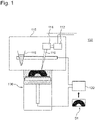
- FIG. 1 illustrates a schematic view of an AM apparatus according to the present embodiment.
- an AM apparatus 100 includes a process chamber 110, a control device 120, and a fabrication unit 130.
- a beam source 112, a scanning device 114, and a powder distributor 116 are disposed inside the process chamber 110.
- the beam source 112 can be configured to generate, for example, an electron beam 118.
- the scanning device 114 can be, for example, a deflection coil for controlling a position irradiated with the electron beam 118.
- the beam source 112 may be configured to generate a laser beam.
- the scanning device 114 can include a mirror, a lens, or the like that deflects the laser beam.
- Metal powder (corresponding to one example of a fabrication material) supported on a base plate of the fabrication unit 130 is irradiated with the beam generated by the beam source 112.
- the base plate will be described below.
- powder such as SUS 316L, a titanium alloy, an aluminum alloy, a magnesium alloy, a copper alloy, and a nickel alloy can be employed as the metal powder.
- the powder distributor 116 is disposed so as to generate a thin layer of the metal powder on the base plate of the fabrication unit 130.
- the base plate will be described below. More specifically, the powder distributor 116 includes a hopper capable of storing the metal powder therein, and is horizontally movably configured.
- a vacuum environment suitable to generate the electron beam 118 is maintained by, for example, a not-illustrated vacuum system inside the process chamber 110 to prevent oxidation of the metal powder in the powder distributor 116 and the fabrication unit 130.
- inert gas such as nitrogen, helium, and argon, may be supplied from a not-illustrated gas supply source into the process chamber 110.
- the control device 120 is communicably connected to the beam source 112, the scanning device 114, the powder distributor 116, and the fabrication unit 130.
- the control device 120 generates execution data such as a beam irradiation position, a beam track, or the like for each layer based on three-dimensional CAD data D1, and controls the beam source 112, the scanning device 114, the powder distributor 116, and the fabrication unit 130 based on this execution data. More specifically, the control device 120 controls the output of the beam source 112, the beam irradiation position and the beam track by the scanning device 114, the supply of the powder by the powder distributor 116, and a driving device 30 (refer to, for example, Fig. 2A ) of the fabrication unit 130.
- the driving device 30 will be described below.
- Fig. 2A is a schematic side view of the fabrication unit 130.
- Fig. 2B is a schematic top view of the fabrication unit 130.
- the fabrication unit 130 includes a base plate 10 supporting the metal powder, a rod 20 connected to the base plate 10, and the driving device 30 configured to lift and lower the rod 20 and the base plate 10.
- the fabrication unit 130 includes a chamber 40 surrounding around at least the base plate 10.
- the base plate 10 "supporting the metal powder” includes the base plate 10 directly supporting the metal powder, and the base plate 10 indirectly supporting the metal powder via, for example, a metallic plate 60, which will be described below.
- the base plate 10 of the fabrication unit 130 includes a plurality of divided base plates 10a adjacent to each other.
- the shape of each of the divided base plates 10a in a planar view is substantially quadrangular, and the divided base plates 10a are formed by dividing the base plate 10 in a grid-like manner.
- a gap between the adjacent divided base plates 10a can be set so as to prevent the metal powder from entering therein as much as possible and also prevent excessive friction from occurring between the adjacent divided base plates 10a.
- the plurality of divided base plates 10a is positioned in such a manner that they are located at the uppermost position and the upper surfaces of all of the divided base plates 10a are arranged in a coplanar manner.
- the base plate 10 can be made from, for example, thermally resistant metal or ceramics such as alumina.
- the rod 20 of the fabrication unit 130 includes a plurality of rods 20a, which is connected to the lower surface sides of the plurality of divided base plates 10a, respectively.
- the driving device 30 of the fabrication unit 130 includes a plurality of driving devices 30a, which individually independently lifts and lowers the plurality of rods 20a and the plurality of divided base plates 10a, respectively.
- the control device 120 illustrated in Fig. 1 is configured to control the plurality of divided base plates 10a individually independently.
- the plurality of driving devices 30a can be, for example, a stepping motor, a hydraulic cylinder, or a pinion gear.
- the plurality of driving devices 30a is a pinion gear
- the plurality of rods 20a includes a groove corresponding to the pinion gear, and functions as a rack gear.
- the plurality of driving devices 30a is fixed to a support plate 50.
- the plurality of rods 20a and the plurality of driving devices 30a are provided for the plurality of divided base plates 10a, respectively, so as to correspond to them one-on-one in the example illustrated in Figs. 2A and 2B , but are not limited thereto.
- the rod 20a and the driving device 30a may be provided only to the divided base plate 10a that should be lifted and lowered among the plurality of divided base plates 10a.
- the AM apparatus 100 may be configured to lift and lower two or more divided base plates 10a among the plurality of divided base plates 10a by a single driving device 30a.
- Fig. 3 is a schematic side cross-sectional view of the fabrication unit 130 with the fabricated object partially created.
- Fig. 4 is a schematic side cross-sectional view of the fabrication unit 130 with the fabricated object entirely created.
- the control device 120 generates a thin layer corresponding to one layer of the metal powder on the divided base plates 10a by controlling the powder distributor 116.
- control device 120 controls the beam source 112 and the scanning device 114 based on the execution data such as the beam irradiation position or the beam track for each layer that is generated from the three-dimensional CAD data D1, thereby irradiating a desired irradiation position with the beam and sintering the metal powder, and thus creating a first layer of a fabricated object M1.
- the control device 120 lowers a part of the divided base plates 10a based on the above-described execution data. More specifically, the control device 120 lowers at least the divided base plates 10a supporting the first layer of the fabricated object M1, and lowers the divided base plates 10a corresponding to a beam irradiation position for a second layer as necessary. At this time, the divided base plates 10a are lowered only by, for example, 10 ⁇ m to 100 ⁇ m as a thickness corresponding to one layer. Subsequently, the control device 120 replenishes the metal powder onto the lowered divided base plates 10a by controlling the powder distributor 116.
- the metal powder is replenished onto the lowered divided base plates 10a in such a manner that the height of the metal powder on the divided base plates 10a located at an initial position where the divided base plates 10a are not lowered and the height of the metal powder on the lowered divided base plates 10a substantially match each other.
- the control device 120 controls the beam source 112 and the scanning device 114, thereby irradiating a desired irradiation position with the beam and sintering the metal powder, and thus creating the second layer of the fabricated object M1.As illustrated in Fig. 3 , when a plurality of layers of the fabricated object M1 is created, the divided base plates 10a supporting the fabricated object M1 among the plurality of divided base plates 10a are lowered.
- the fabrication unit 130 can create the entire fabricated object M1 as illustrated in Fig. 4 by repeating the above-described processing for each layer.
- the fabricated object M1 illustrated in Figs. 3 and 4 has a substantially dorm-like shape.
- the AM apparatus 100 includes the plurality of divided base plates 10a adjacent to each other, thereby being able to reduce the amount of metal powder required to create the fabricated object M1 compared to when the base plate 10 is entirely lowered by lowering only the divided base plates 10a supporting each layer.
- the AM apparatus 100 can reduce the amount of metal powder around the fabricated object that is indirectly melted due to the sintering of the metal powder, thereby reducing a loss of the metal powder.
- the AM apparatus 100 can reduce the amount of unsintered metal powder around the fabricated object, thereby also reducing time and labor to perform the processing for regenerating the oxidized metal powder.
- the AM apparatus 100 can reduce the amount of metal powder required to create the fabricated object M1, thereby also reducing time and labor to flatly deposit the metal powder all over the base plate 10 and time and labor to collect the unsintered metal powder after the fabricated object M1 is sintered.
- the AM apparatus 100 can reduce the amount of a support member required to support the fabricated object M1 by lowering each of the divided plates 10a according to the shape of the fabricated object M1 to be created, thereby also reducing the amount of metal powder used for the support member as a result thereof.
- the AM apparatus 100 includes the driving device 30, which can lift and lower the plurality of divided base plates 10a independently. Due to this configuration, the AM apparatus 100 can lower and lift a part of the plurality of divided base plates 10a according to the shape of the fabricated object M1.Further, in the present embodiment, the plurality of driving devices 30a is provided for the plurality of divided base plates 10a, respectively. Due to this configuration, the AM apparatus 100 can lift and lower the plurality of divided base plates 10a individually independently, thereby lowering and lifting the plurality of divided base plates 10a according to the shape of the fabricated object M1 further flexibly. As a result, the AM apparatus 100 can further reduce the amount of metal powder required to create the fabricated object M1.
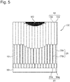
- FIG. 5 is a schematic side cross-sectional view of the fabrication unit 130 with another fabricated object partially created.
- Fig. 6 is a schematic side cross-sectional view of the fabrication unit 130 with the other fabricated object entirely created.
- the divided base plates 10a supporting the fabricated object M2 are lowered.
- the control device 120 lowers at least the divided base plates 10a supporting the fabricated object M2 and lowers the divided base plates 10a corresponding to the beam irradiation position for the next layer as necessary based on the execution data.
- the fabrication unit 130 can create the entire fabricated object M2 as illustrated in Fig. 6 by repeating the above-described processing for each layer.
- the fabricated object M2 illustrated in Figs. 5 and 6 has a substantially inverted dome-like shape.
- a support member may be generated between the base plate 10 and the fabricated object M2 as necessary.
- FIG. 7 is a schematic side cross-sectional view illustrating another example of the fabrication unit 130.
- the fabrication unit 130 illustrated in Fig. 7 includes the metallic plate 60 on the upper surface of the base plate 10.
- the metallic plate 60 is fixed to the upper surface of the base plate 10 by, for example, a fastening unit such as a bolt.
- the fastening unit for fixing the metallic plate 60 to the base plate 10 is provided at a position uninfluential on the creation of the fabricated object.
- the metallic plate 60 includes a plurality of metallic plates 60a, which is fixed to the plurality of divided base plates 10a, respectively.
- the metallic plate 60 is not limited thereto, and a single metallic plate 60a may be fixed to two or more divided base plates 10a among the plurality of divided base plates 10a.
- the two or more divided base plates 10a with the single metallic plate 60a fixed thereto can be integrally lifted and lowered by the driving device 30.
- the fabricated object is extracted from the AM apparatus 100.
- the metallic plate 60a which the fabricated object is in contact with, is unfixed from the divided base plate 10a.
- the fabricated object is detached from the fabrication unit 130 together with the metallic plate 60a, and the metallic plate 60a and the fabricated object are separated off from each other by wire electrical discharge machining after being thermally processed.
- the base plate 10 supports the metal powder via the metallic plate 60. Due to this configuration, the fabricated object is created on the metallic plate 60, and therefore can be easily extracted from the AM apparatus 100 by demounting the metallic plate 60 from the base plate 10. Further, the metallic plate 60 includes the plurality of metallic plates 60a, and therefore even an increase in the size of the fabricated object can be handled smoothly by separating each of the plurality of metallic plates 60a off from the fabricated object. Therefore, the fabricated object and the plurality of metallic plates 60a can be easily separated off from each other compared to when a large-size base plate and a large-size fabricated object are separated off from each other.
- FIG. 8 is a schematic top view of another example of the fabrication unit 130.
- Fig. 9 is a schematic top view of further another example of the fabrication unit 130.
- each of the divided base plates 10a of the fabrication unit 130 has a substantially rectangular shape in a planar view, and the divided base plates 10a are formed by dividing the base plate 10 into rectangles.
- each of the divided base plates 10a of the fabrication unit 130 has a substantially regular hexagonal shape in a planar view, and the divided base plates 10a are formed by dividing the base plate 10 in a honeycomb manner.
- Fig. 8 is a schematic top view of another example of the fabrication unit 130.
- Fig. 9 is a schematic top view of further another example of the fabrication unit 130.
- each of the divided base plates 10a of the fabrication unit 130 has a substantially rectangular shape in a planar view, and the divided base plates 10a are formed by dividing the base plate 10 into rectangles.
- each of the divided base plates 10a of the fabrication unit 130 has a substantially regular hexagonal
- a divided base plate 10a having a shape other than the substantially regular hexagonal shape can be provided as appropriate to reduce the gap between the chamber 40 and the divided base plate 10a.
- the base plate 10 of the fabrication unit 130 illustrated in Figs. 3 to 7 may be divided as illustrated in Fig. 8 or 9 .
- an AM apparatus configured to support a fabrication material, and a beam source configured to generate a beam with which the fabrication material supported on the base plate is irradiated.
- the base plate includes a plurality of divided base plates adjacent to each other.
- the AM apparatus includes the plurality of divided base plates adjacent to each other, thereby being able to reduce the amount of the fabrication material required to create a fabricated object compared to when the base plate is entirely lowered by lowering only the divided base plate supporting each layer.
- the AM apparatus can reduce the amount of the fabrication material around the fabricated object that is indirectly melted due to the sintering of the fabrication material, thereby reducing a loss of the fabrication material.
- the AM apparatus can reduce the amount of the fabrication material unsintered around the fabricated object, thereby also reducing time and labor to perform processing for regenerating the oxidized fabrication material.
- the AM apparatus can reduce the amount of the fabrication material required to create the fabricated object, thereby also reducing time and labor t to flatly deposit the fabrication material all over the base plate and time and labor to collect the unsintered fabrication material after the fabricated object is sintered. Further, the AM apparatus can reduce the amount of a support member required to support the fabricated object by lowering each of the divided plates according to the shape of the fabricated object to be created, thereby also reducing the amount of the metal powder used for the support member as a result thereof.
- the AM apparatus further includes a driving device configured to lift and lower the plurality of divided base plates independently.
- the AM apparatus includes the driving device, which can raise and lower the plurality of divided base plates independently. Due to this configuration, the AM apparatus can lower and lift a part of the plurality of divided base plates according to the shape of the fabricated object.
- the driving device includes a plurality of driving devices provided to the plurality of divided base plates, respectively.
- the plurality of driving device is provided for the plurality of divided base plates, respectively. Due to this configuration, the AM apparatus can lift and lower the plurality of divided base plates individually independently, thereby lowering and lifting the plurality of divided base plates according to the shape of the fabricated object further flexibly. As a result, the AM apparatus can further reduce the amount of the fabrication material required to create the fabricated object.
- the AM apparatus according to any of the first configuration to the third configuration includes a metallic plate detachably attachably fixed on the base plate.
- the base plate supports the fabrication material via the metallic plate. Due to this configuration, the fabricated object is created on the metallic plate, and therefore can be easily extracted from the AM apparatus by demounting the metallic plate from the base plate.
- the metallic plate includes a plurality of metallic plates fixed to the plurality of divided base plates, respectively.
- the metallic plate includes the plurality of metallic plates, and therefore even an increase in the size of the fabricated object can be handled smoothly by separating each of the plurality of metallic plates off from the fabricated object. Therefore, the fabricated object and the plurality of metallic plates can be easily separated off from each other compared to when a large-size base plate and a large-size fabricated object are separated off from each other.
- a method for manufacturing a fabricated object includes supporting a fabrication material on a plurality of divided base plates adjacent to each other, irradiating the fabrication material supported on the plurality of divided base plates with a beam, and lowering a part of the plurality of divided base plates.
- the method includes lowering a part of the divided base plates adjacent to each other, thereby being able to reduce the amount of the fabrication material required to create the fabricated object compared to when the base plate is entirely lowered.
- the method can reduce the amount of the fabrication material around the fabricated object that is indirectly melted due to the sintering of the fabrication material, thereby reducing a loss of the fabrication material.
- the method can reduce the amount of the fabrication material unsintered around the fabricated object, thereby also reducing time and labor to perform processing for regenerating the oxidized fabrication material.
- the method can reduce the amount of the fabrication material required to create the fabricated object, thereby also reducing time and labor t to flatly deposit the fabrication material all over the base plate and time and labor to collect the unsintered fabrication material after the fabricated object is sintered.
- the AM apparatus can reduce the amount of a support member required to support the fabricated object by lowering each of the divided plates according to the shape of the fabricated object to be created, thereby also reducing the amount of metal powder used for the support member as a result thereof.
Landscapes
- Engineering & Computer Science (AREA)
- Chemical & Material Sciences (AREA)
- Manufacturing & Machinery (AREA)
- Materials Engineering (AREA)
- Physics & Mathematics (AREA)
- Plasma & Fusion (AREA)
- Mechanical Engineering (AREA)
- Optics & Photonics (AREA)
- Health & Medical Sciences (AREA)
- General Health & Medical Sciences (AREA)
- Toxicology (AREA)
- Powder Metallurgy (AREA)
Applications Claiming Priority (2)
| Application Number | Priority Date | Filing Date | Title |
|---|---|---|---|
| JP2019094592A JP2020190003A (ja) | 2019-05-20 | 2019-05-20 | Am装置及び造形物の製造方法 |
| PCT/JP2020/013580 WO2020235214A1 (ja) | 2019-05-20 | 2020-03-26 | Am装置及び造形物の製造方法 |
Publications (2)
| Publication Number | Publication Date |
|---|---|
| EP3974085A1 true EP3974085A1 (de) | 2022-03-30 |
| EP3974085A4 EP3974085A4 (de) | 2023-01-25 |
Family
ID=73453425
Family Applications (1)
| Application Number | Title | Priority Date | Filing Date |
|---|---|---|---|
| EP20810489.3A Withdrawn EP3974085A4 (de) | 2019-05-20 | 2020-03-26 | Am-vorrichtung und verfahren zur herstellung eines formobjekts |
Country Status (5)
| Country | Link |
|---|---|
| US (1) | US20220226899A1 (de) |
| EP (1) | EP3974085A4 (de) |
| JP (1) | JP2020190003A (de) |
| CN (1) | CN113874139A (de) |
| WO (1) | WO2020235214A1 (de) |
Families Citing this family (2)
| Publication number | Priority date | Publication date | Assignee | Title |
|---|---|---|---|---|
| US11633914B2 (en) * | 2020-10-16 | 2023-04-25 | International Business Machines Corporation | Configurable printing bed for 3D printing |
| US12226949B2 (en) * | 2022-05-25 | 2025-02-18 | The Boeing Company | Model based supporting spokes activation to aid 3D printing |
Family Cites Families (11)
| Publication number | Priority date | Publication date | Assignee | Title |
|---|---|---|---|---|
| DE19511772C2 (de) | 1995-03-30 | 1997-09-04 | Eos Electro Optical Syst | Vorrichtung und Verfahren zum Herstellen eines dreidimensionalen Objektes |
| US8206637B2 (en) * | 2008-10-14 | 2012-06-26 | The Boeing Company | Geometry adaptive laser sintering system |
| DE202011003443U1 (de) * | 2011-03-02 | 2011-12-23 | Bego Medical Gmbh | Vorrichtung zur generativen Herstellung dreidimensionaler Bauteile |
| DE102011005929A1 (de) * | 2011-03-23 | 2012-09-27 | Bayerische Motoren Werke Aktiengesellschaft | Vorrichtung und Verfahren zum Herstellen eines Bauteils in Schichtbauweise |
| US9505057B2 (en) | 2013-09-06 | 2016-11-29 | Arcam Ab | Powder distribution in additive manufacturing of three-dimensional articles |
| US20170282462A1 (en) * | 2014-10-01 | 2017-10-05 | Panasonic Intellectual Property Management Co., Lt d. | Method for manufacturing three-dimensional shaped object |
| DE102016201369A1 (de) * | 2016-01-29 | 2017-08-03 | Siemens Aktiengesellschaft | Vorrichtung, Anlage und Verfahren zur additiven Herstellung eines Bauteils |
| DE102016225178A1 (de) * | 2016-12-15 | 2018-06-21 | MTU Aero Engines AG | Schichtbauvorrichtung und Schichtbauverfahren zum additiven Herstellen zumindest eines Bauteilbereichs eines Bauteils |
| US11472105B2 (en) * | 2017-01-09 | 2022-10-18 | International Business Machines Corporation | Methods and systems for 3D printing with modifiable support |
| EP3351321A1 (de) * | 2017-01-24 | 2018-07-25 | Siemens Aktiengesellschaft | Vorrichtung und verfahren zur additiven fertigung wenigstens eines formkörpers |
| US11485091B2 (en) * | 2017-06-02 | 2022-11-01 | University Of Southern California | Automatic reusable support for 3D printing |
-
2019
- 2019-05-20 JP JP2019094592A patent/JP2020190003A/ja active Pending
-
2020
- 2020-03-26 EP EP20810489.3A patent/EP3974085A4/de not_active Withdrawn
- 2020-03-26 WO PCT/JP2020/013580 patent/WO2020235214A1/ja not_active Ceased
- 2020-03-26 CN CN202080037344.3A patent/CN113874139A/zh active Pending
- 2020-03-26 US US17/611,365 patent/US20220226899A1/en not_active Abandoned
Also Published As
| Publication number | Publication date |
|---|---|
| WO2020235214A1 (ja) | 2020-11-26 |
| JP2020190003A (ja) | 2020-11-26 |
| CN113874139A (zh) | 2021-12-31 |
| US20220226899A1 (en) | 2022-07-21 |
| EP3974085A4 (de) | 2023-01-25 |
Similar Documents
| Publication | Publication Date | Title |
|---|---|---|
| US11235393B2 (en) | Additive manufacturing apparatus and method of producing three-dimensionally shaped object | |
| JP6389242B2 (ja) | 付加製造のためのビルドプレート及び装置 | |
| EP3974085A1 (de) | Am-vorrichtung und verfahren zur herstellung eines formobjekts | |
| EP2828068B1 (de) | Substrat zur generativen herstellung | |
| US9707718B2 (en) | Method of fabricating a part by selective melting or selective sintering of powder beds by means of a high energy beam | |
| EP3417961B1 (de) | Halterung zur generativen fertigung | |
| CN113631303A (zh) | 增材制造 | |
| JP6639735B2 (ja) | 三次元造形装置 | |
| EP2907896A1 (de) | Filmformungsverfahren und filmformungsvorrichtung | |
| US20190009368A1 (en) | Methods and support structures leveraging grown build envelope | |
| CN108284230A (zh) | 添加制造方法 | |
| JP7041293B1 (ja) | 三次元造形物の製造方法およびシート裁断装置の製造方法 | |
| EP2978000A1 (de) | Korngrenzendiffusionsprozessvorrichtung und behälter für die korngrenzendiffusionsprozessvorrichtung | |
| US11123798B2 (en) | Method for manufacturing a semi-finished product and a workpiece | |
| EP3705215A1 (de) | Verfahren zur herstellung eines metallelements | |
| EP4026634A1 (de) | Am-vorrichtung | |
| EP3461572A1 (de) | Konstruktionsplatte zur generativen fertigung und verfahren | |
| JP2019011485A (ja) | 積層造形体の製造装置および製造方法 | |
| EP3023176B1 (de) | Kontaktanordnung zur verwendung in einer vorrichtung zur herstellung von dreidimensionalen werkstücken | |
| US11141916B2 (en) | Apparatus for additively manufacturing of three-dimensional objects | |
| JP2010034404A (ja) | レーザアニール処理装置 | |
| JP2025117669A (ja) | 金属付加製造物の製造方法 | |
| JP7607426B2 (ja) | 積層造形方法およびサポート部材の設計方法 | |
| JP7312063B2 (ja) | 三次元物体の製造方法及び三次元造形装置 | |
| EP3299098A1 (de) | Verbesserte generative schichtfertigung |
Legal Events
| Date | Code | Title | Description |
|---|---|---|---|
| STAA | Information on the status of an ep patent application or granted ep patent |
Free format text: STATUS: THE INTERNATIONAL PUBLICATION HAS BEEN MADE |
|
| PUAI | Public reference made under article 153(3) epc to a published international application that has entered the european phase |
Free format text: ORIGINAL CODE: 0009012 |
|
| STAA | Information on the status of an ep patent application or granted ep patent |
Free format text: STATUS: REQUEST FOR EXAMINATION WAS MADE |
|
| 17P | Request for examination filed |
Effective date: 20211116 |
|
| AK | Designated contracting states |
Kind code of ref document: A1 Designated state(s): AL AT BE BG CH CY CZ DE DK EE ES FI FR GB GR HR HU IE IS IT LI LT LU LV MC MK MT NL NO PL PT RO RS SE SI SK SM TR |
|
| DAV | Request for validation of the european patent (deleted) | ||
| DAX | Request for extension of the european patent (deleted) | ||
| A4 | Supplementary search report drawn up and despatched |
Effective date: 20230104 |
|
| RAP3 | Party data changed (applicant data changed or rights of an application transferred) |
Owner name: EBARA CORPORATION |
|
| RIC1 | Information provided on ipc code assigned before grant |
Ipc: B22F 12/30 20210101ALI20221222BHEP Ipc: B22F 10/40 20210101ALI20221222BHEP Ipc: B22F 10/28 20210101ALI20221222BHEP Ipc: B29C 64/245 20170101ALI20221222BHEP Ipc: B29C 64/232 20170101ALI20221222BHEP Ipc: B29C 64/153 20170101ALI20221222BHEP Ipc: B33Y 30/00 20150101ALI20221222BHEP Ipc: B33Y 10/00 20150101ALI20221222BHEP Ipc: B22F 3/16 20060101ALI20221222BHEP Ipc: B22F 3/105 20060101AFI20221222BHEP |
|
| RAP3 | Party data changed (applicant data changed or rights of an application transferred) |
Owner name: EBARA CORPORATION |
|
| STAA | Information on the status of an ep patent application or granted ep patent |
Free format text: STATUS: THE APPLICATION IS DEEMED TO BE WITHDRAWN |
|
| 18D | Application deemed to be withdrawn |
Effective date: 20230804 |