EP3974008A1 - Blood purification device - Google Patents
Blood purification device Download PDFInfo
- Publication number
- EP3974008A1 EP3974008A1 EP20810584.1A EP20810584A EP3974008A1 EP 3974008 A1 EP3974008 A1 EP 3974008A1 EP 20810584 A EP20810584 A EP 20810584A EP 3974008 A1 EP3974008 A1 EP 3974008A1
- Authority
- EP
- European Patent Office
- Prior art keywords
- liquid chemical
- cleaning
- piping
- liquid
- sensors
- Prior art date
- Legal status (The legal status is an assumption and is not a legal conclusion. Google has not performed a legal analysis and makes no representation as to the accuracy of the status listed.)
- Granted
Links
Images

Classifications
-
- A—HUMAN NECESSITIES
- A61—MEDICAL OR VETERINARY SCIENCE; HYGIENE
- A61M—DEVICES FOR INTRODUCING MEDIA INTO, OR ONTO, THE BODY; DEVICES FOR TRANSDUCING BODY MEDIA OR FOR TAKING MEDIA FROM THE BODY; DEVICES FOR PRODUCING OR ENDING SLEEP OR STUPOR
- A61M1/00—Suction or pumping devices for medical purposes; Devices for carrying-off, for treatment of, or for carrying-over, body-liquids; Drainage systems
- A61M1/14—Dialysis systems; Artificial kidneys; Blood oxygenators ; Reciprocating systems for treatment of body fluids, e.g. single needle systems for hemofiltration or pheresis
- A61M1/16—Dialysis systems; Artificial kidneys; Blood oxygenators ; Reciprocating systems for treatment of body fluids, e.g. single needle systems for hemofiltration or pheresis with membranes
- A61M1/1601—Control or regulation
- A61M1/1603—Regulation parameters
- A61M1/1605—Physical characteristics of the dialysate fluid
- A61M1/1607—Physical characteristics of the dialysate fluid before use, i.e. upstream of dialyser
-
- A—HUMAN NECESSITIES
- A61—MEDICAL OR VETERINARY SCIENCE; HYGIENE
- A61M—DEVICES FOR INTRODUCING MEDIA INTO, OR ONTO, THE BODY; DEVICES FOR TRANSDUCING BODY MEDIA OR FOR TAKING MEDIA FROM THE BODY; DEVICES FOR PRODUCING OR ENDING SLEEP OR STUPOR
- A61M1/00—Suction or pumping devices for medical purposes; Devices for carrying-off, for treatment of, or for carrying-over, body-liquids; Drainage systems
- A61M1/14—Dialysis systems; Artificial kidneys; Blood oxygenators ; Reciprocating systems for treatment of body fluids, e.g. single needle systems for hemofiltration or pheresis
- A61M1/16—Dialysis systems; Artificial kidneys; Blood oxygenators ; Reciprocating systems for treatment of body fluids, e.g. single needle systems for hemofiltration or pheresis with membranes
- A61M1/168—Sterilisation or cleaning before or after use
-
- A—HUMAN NECESSITIES
- A61—MEDICAL OR VETERINARY SCIENCE; HYGIENE
- A61M—DEVICES FOR INTRODUCING MEDIA INTO, OR ONTO, THE BODY; DEVICES FOR TRANSDUCING BODY MEDIA OR FOR TAKING MEDIA FROM THE BODY; DEVICES FOR PRODUCING OR ENDING SLEEP OR STUPOR
- A61M1/00—Suction or pumping devices for medical purposes; Devices for carrying-off, for treatment of, or for carrying-over, body-liquids; Drainage systems
- A61M1/14—Dialysis systems; Artificial kidneys; Blood oxygenators ; Reciprocating systems for treatment of body fluids, e.g. single needle systems for hemofiltration or pheresis
- A61M1/16—Dialysis systems; Artificial kidneys; Blood oxygenators ; Reciprocating systems for treatment of body fluids, e.g. single needle systems for hemofiltration or pheresis with membranes
- A61M1/1601—Control or regulation
-
- A—HUMAN NECESSITIES
- A61—MEDICAL OR VETERINARY SCIENCE; HYGIENE
- A61M—DEVICES FOR INTRODUCING MEDIA INTO, OR ONTO, THE BODY; DEVICES FOR TRANSDUCING BODY MEDIA OR FOR TAKING MEDIA FROM THE BODY; DEVICES FOR PRODUCING OR ENDING SLEEP OR STUPOR
- A61M1/00—Suction or pumping devices for medical purposes; Devices for carrying-off, for treatment of, or for carrying-over, body-liquids; Drainage systems
- A61M1/14—Dialysis systems; Artificial kidneys; Blood oxygenators ; Reciprocating systems for treatment of body fluids, e.g. single needle systems for hemofiltration or pheresis
- A61M1/16—Dialysis systems; Artificial kidneys; Blood oxygenators ; Reciprocating systems for treatment of body fluids, e.g. single needle systems for hemofiltration or pheresis with membranes
- A61M1/1654—Dialysates therefor
- A61M1/1656—Apparatus for preparing dialysates
- A61M1/1657—Apparatus for preparing dialysates with centralised supply of dialysate or constituent thereof for more than one dialysis unit
-
- A—HUMAN NECESSITIES
- A61—MEDICAL OR VETERINARY SCIENCE; HYGIENE
- A61M—DEVICES FOR INTRODUCING MEDIA INTO, OR ONTO, THE BODY; DEVICES FOR TRANSDUCING BODY MEDIA OR FOR TAKING MEDIA FROM THE BODY; DEVICES FOR PRODUCING OR ENDING SLEEP OR STUPOR
- A61M1/00—Suction or pumping devices for medical purposes; Devices for carrying-off, for treatment of, or for carrying-over, body-liquids; Drainage systems
- A61M1/14—Dialysis systems; Artificial kidneys; Blood oxygenators ; Reciprocating systems for treatment of body fluids, e.g. single needle systems for hemofiltration or pheresis
- A61M1/16—Dialysis systems; Artificial kidneys; Blood oxygenators ; Reciprocating systems for treatment of body fluids, e.g. single needle systems for hemofiltration or pheresis with membranes
- A61M1/168—Sterilisation or cleaning before or after use
- A61M1/169—Sterilisation or cleaning before or after use using chemical substances
-
- A—HUMAN NECESSITIES
- A61—MEDICAL OR VETERINARY SCIENCE; HYGIENE
- A61M—DEVICES FOR INTRODUCING MEDIA INTO, OR ONTO, THE BODY; DEVICES FOR TRANSDUCING BODY MEDIA OR FOR TAKING MEDIA FROM THE BODY; DEVICES FOR PRODUCING OR ENDING SLEEP OR STUPOR
- A61M2205/00—General characteristics of the apparatus
- A61M2205/18—General characteristics of the apparatus with alarm
-
- A—HUMAN NECESSITIES
- A61—MEDICAL OR VETERINARY SCIENCE; HYGIENE
- A61M—DEVICES FOR INTRODUCING MEDIA INTO, OR ONTO, THE BODY; DEVICES FOR TRANSDUCING BODY MEDIA OR FOR TAKING MEDIA FROM THE BODY; DEVICES FOR PRODUCING OR ENDING SLEEP OR STUPOR
- A61M2205/00—General characteristics of the apparatus
- A61M2205/33—Controlling, regulating or measuring
- A61M2205/3306—Optical measuring means
-
- A—HUMAN NECESSITIES
- A61—MEDICAL OR VETERINARY SCIENCE; HYGIENE
- A61M—DEVICES FOR INTRODUCING MEDIA INTO, OR ONTO, THE BODY; DEVICES FOR TRANSDUCING BODY MEDIA OR FOR TAKING MEDIA FROM THE BODY; DEVICES FOR PRODUCING OR ENDING SLEEP OR STUPOR
- A61M2205/00—General characteristics of the apparatus
- A61M2205/33—Controlling, regulating or measuring
- A61M2205/3317—Electromagnetic, inductive or dielectric measuring means
-
- A—HUMAN NECESSITIES
- A61—MEDICAL OR VETERINARY SCIENCE; HYGIENE
- A61M—DEVICES FOR INTRODUCING MEDIA INTO, OR ONTO, THE BODY; DEVICES FOR TRANSDUCING BODY MEDIA OR FOR TAKING MEDIA FROM THE BODY; DEVICES FOR PRODUCING OR ENDING SLEEP OR STUPOR
- A61M2205/00—General characteristics of the apparatus
- A61M2205/33—Controlling, regulating or measuring
- A61M2205/3324—PH measuring means
Definitions
- the invention relates to a blood purification device.
- a cleaning/disinfecting process for cleaning/disinfecting the inside of piping is performed after blood purification therapy.
- a cleaning/disinfection liquid chemical is introduced into the piping and the inside of the piping is cleaned/disinfected (see, e.g., Patent Document 1).
- Patent Document 1 JP2014-097197A
- a blood purification device into which a liquid chemical is introduced from an external device could receive data of the type of liquid chemical used from the external device by communication, etc.
- each blood purification device identifies the type of the actually supplied liquid chemical and determines whether the correct liquid chemical is supplied.
- the invention according to claim 1 provides a blood purification device for blood purification therapy performed through a blood purifier, the blood purification device comprising:
- the invention according to claim 2 is the blood purification device according to claim 1 , wherein the liquid chemical identification unit selects all or part of the plurality of sensors according to the type of the liquid chemical which should be used for cleaning/disinfection and, based on detection results from the selected all or part of sensors, identifies whether or not it is a liquid chemical which should be used for the cleaning/disinfection.
- the invention according to claim 3 is the blood purification device according to claim 1 or 2 , wherein the liquid chemical identification unit is configured to be able to identify types of the liquid chemicals of more than the number of the plurality of sensors based on a combination of the detection results from the plurality of sensors.
- the invention according to claim 4 is the blood purification device according to any one of claims 1 to 3 , further comprising: a cleaning/disinfection control unit to detect whether the piping is filled with the cleaning/disinfection liquid chemical at the time of cleaning/disinfecting the piping, based on a detection result from at least one of the plurality of sensors.
- the invention according to claim 5 is the blood purification device according to claim 4 , wherein the cleaning/disinfection control unit is configured to be able to detect whether a dialysate or the liquid chemical in the piping has been replaced with dialysis water, based on a detection result from at least one of the plurality of sensors.
- the invention according to claim 6 is the blood purification device according to any one of claims 1 to 5 , wherein the plurality of sensors comprise a conductivity sensor to measure conductivity of a liquid flowing through the piping, and an absorbance sensor to measure absorption of ultraviolet light by the liquid flowing through the piping.
- the invention according to claim 7 is the blood purification device according to claim 6 , wherein the liquid chemical identification unit identifies a type of the liquid chemical by comparing a threshold for a detection value of the conductivity sensor and a threshold for a detection value of the absorbance sensor, which are set for each type of the liquid chemical, with the detection values of the conductivity sensor and the absorbance sensor.
- the sensors since the sensors respectively detect conductivity and absorbance, it is possible to detect liquid chemicals having different compositions and possible to identify more types of cleaning/disinfection liquid chemicals.
- an acid cleaning solution a peracetic acid-based disinfectant and a hypochlorite disinfectant, which are typical liquid chemicals used for the cleaning/disinfecting process.
- FIG. 1 is a schematic configuration diagram illustrating a blood purification system using blood purification devices in the present embodiment.
- a blood purification system 10 includes a dialysate supply device 11 and plural blood purification devices 1.
- the dialysate supply device 11 prepares a dialysate with a predetermined concentration using dialysis water supplied from a water treatment device (not shown) and an undiluted dialysate fluid supplied from a dissolving device (not shown), and supplies the prepared dialysate to each blood purification device 1.
- the dialysate prepared by the dialysate supply device 11 is supplied to each blood purification device 1 via a dialysate supply line 12.
- Each blood purification device 1 is connected to a blood purifier (a dialyzer, not shown) for providing blood purification therapy (dialysis therapy) to a patient and supplies the dialysate supplied from the dialysate supply device 11 to the blood purifier.
- a blood purifier a dialyzer, not shown
- the details of the blood purification device 1 will be described later.
- the blood purification system 10 is configured such that the dialysate supply device 11 can communicate with each blood purification device 1 via a signal line 13.
- the dialysate supply device 11 can detect an operating status of each blood purification device 1 and control each blood purification device 1.
- the form of communication between the dialysate supply device 11 and each blood purification device 1 is not limited thereto and may be, e.g., wireless communication instead of wired communication.
- a cleaning/disinfecting process for cleaning/disinfecting the inside of piping is performed after blood purification therapy.
- the cleaning/disinfecting process here includes a case where only cleaning is performed, a case where only disinfection is performed, and a case where both cleaning and disinfection are performed.
- the dialysate supply device 11 prepares a liquid chemical used for cleaning/disinfection and supplies the prepared liquid chemical to each blood purification device 1 via the dialysate supply line 12.
- the dialysate supply device 11 also has a function of notifying each blood purification device 1 of the type, etc., of liquid chemical to be used when performing the cleaning/disinfecting process.
- the cleaning/disinfecting process for the dialysate supply device 11 and each blood purification device 1 is automatically performed according to a program preset in the dialysate supply device 11.
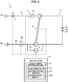
- FIG. 2 is a schematic configuration diagram illustrating the blood purification device 1.
- FIG. 2 schematically shows piping arrangement during cleaning/disinfection.
- the blood purification device 1 has a pair of connectors 2 a, 2 b to which the blood purifier (not shown) is connected.
- the two connectors 2 a, 2 b are connected via a bypass connector 2 c.
- Piping 3 inside the blood purification device 1 has a supply-side flow path 31 including a liquid supply port 3 a connected to the dialysate supply line 12 and the connector 2 a, and a discharge-side flow path 32 including the other connector 2 b and a liquid discharge port 3 b.
- the blood purification device 1 also has a dual pump 5 which is configured to operate so that an amount of liquid supplied to the blood purifier and an amount of liquid discharged from the blood purifier are mechanically equivalent.
- the dual pump 5 is used to control a flow rate of the liquid flowing through the piping 3.
- a removed water flow path 33 is provided on the discharge-side flow path 32 so as to bypass the dual pump 5, and a water removal pump 6 to control an amount of water removed from blood is provided on the removed water flow path 33.
- a liquid supply valve 7 composed of a solenoid valve capable of shutting off liquid supply is provided on the supply-side flow path 31.
- the configuration diagram in FIG. 2 is simplified, and a flow path for bypassing each part, a solenoid valve, a filter unit, a pressure sensor for measuring liquid pressure, a temperature sensor for measuring liquid temperature, etc., may be appropriately provided.
- the blood purification device 1 also includes a control device 8 that controls the dual pump 5 , the water removal pump 6 , the liquid supply valve 7, etc.
- the control device 8 controls each part during blood purification therapy or during cleaning/disinfection.
- the blood purification device 1 in the present embodiment includes plural sensors of different detection types provided on the piping 3 inside the device, and a liquid chemical identification unit 81 that identifies a type of cleaning/disinfection liquid chemical flowing through the piping 3 by using the plural sensors 4.
- the plural sensors 4 are provided on the piping 3 and can detect that a cleaning/disinfection liquid chemical is flowing through the piping 3. In the present embodiment, these plural sensors 4 are used to determine the type of the cleaning/disinfection liquid chemical.
- a conductivity sensor 41 to measure conductivity of a liquid flowing through the piping 3 and an absorbance sensor 42 to measure absorption of ultraviolet light in the 280 -nm band by the liquid flowing through the piping 3 are used as the plural sensors 4.
- the sensors 4 are not limited thereto, and, e.g., a pH sensor to measure pH of the liquid flowing through the pipe 3 , etc., may be included.
- the conductivity sensor 41 is used to monitor a dialysate concentration during blood purification therapy and is provided on the supply-side flow path 31. When the dialysate concentration exceeds a threshold during blood purification therapy, an alarm is issued and is visually or audibly notified via a user interface, such as a display unit (not shown). Meanwhile, the absorbance sensor 42 is used to measure absorbance of waste liquid from the blood purifier, detect an amount of urea nitrogen contained in the waste liquid and monitor the progress of dialysis during blood purification therapy, and is provided on the discharge-side flow path 32.
- the conductivity sensor 41 and the absorbance sensor 42 which are conventionally used in blood purification therapy, are used for a different purpose and are used to determine the type of cleaning/disinfection liquid chemical.
- the system configuration is simplified, and it is possible to reduce the cost.
- Typical liquid chemicals used for cleaning/disinfection include an acid cleaning solution, a peracetic acid-based disinfectant and a hypochlorite disinfectant.
- the acid cleaning solution and the hypochlorite disinfectant have different conductivities from that of the dialysis water and thus can be detected by the conductivity sensor 41.
- the peracetic acid-based disinfectant and the hypochlorite disinfectant exhibit different UV absorbances (ultraviolet light in the 280 -nm band) from that of the dialysis water and thus can be detected by the absorbance sensor 42.
- two or more types (three types in this example) of liquid chemicals can be detected by using two sensors 4.
- the concentration of the liquid chemical can also be detected by detecting conductivity or absorbance. That is, in the present embodiment, the sensors 4 are configured to be able to detect the concentration of the liquid chemical flowing through the piping 3.
- the liquid chemical identification unit 81 is mounted on the control device 8 and is realized by appropriately combining an arithmetic element such as CPU, a storage device such as memory, a software, and an interface, etc.
- the liquid chemical identification unit 81 is configured to be able to identify types of the liquid chemicals of at least not less than the number of the sensors 4 based on detection results from the plural sensors 4.
- the liquid chemical identification unit 81 is configured to be able to identify types of the liquid chemicals of more than the number of the plural sensors 4 based on a combination of the detection results from the plural sensors 4.
- the liquid chemical identification unit 81 identifies the type of the liquid chemical by comparing a threshold (within a reference value range) for a detection value of the conductivity sensor 41 and a threshold (within a reference value range) for a detection value of the absorbance sensor 42, which are set for each type of liquid chemical, with the detection values of the conductivity sensor 41 and the absorbance sensor 42. For example, when the detection values of the conductivity sensor 41 and the absorbance sensor 42 are respectively within the reference value ranges for an acid cleaning solution, it is identified that the liquid chemical is the acid cleaning solution. However, it is not limited thereto.
- the liquid chemical identification unit 81 may identify that the liquid chemical is the acid cleaning solution when only the detection value of the conductivity sensor 41 changes as compared to measurement result of the dialysis water (when the amount of change is not less than a predetermined threshold), the liquid chemical is the peracetic acid-based disinfectant when only the detection value of the absorbance sensor 42 changes (when the amount of change is not less than a predetermined threshold), and the liquid chemical is the hypochlorite disinfectant when the detection values of the conductivity sensor 41 and the absorbance sensor 42 both change (when the amount of change is not less than a predetermined threshold).
- control device 8 is configured to communicate with the dialysate supply device 11 and acquire information indicating the liquid chemical used in the cleaning/disinfecting process from the dialysate supply device 11.
- the liquid chemical identification unit 81 is configured to specify the liquid chemical based on the acquired information indicating the liquid chemical and select the sensor corresponding to the specified liquid chemical from the plural sensors 4.
- the liquid chemical identification unit 81 selects all or part of the plural sensors 4 according to the type of the liquid chemical which should be used for cleaning/disinfection.
- the liquid chemical identification unit 81 is also configured to identify whether or not the liquid chemical used currently is a liquid chemical which should be used for cleaning/disinfection, based on the detection results from the selected all or part of sensors 4.
- the reference value ranges mentioned above are set within a range in which the type of the liquid chemical can be identified. Therefore, by determining whether or not the concentration of the liquid chemical is within the reference value range, it is possible to determine whether or not the type of the liquid chemical is appropriate in addition to whether or not the concentration of the liquid chemical is appropriate.
- the blood purification device 1 also includes a cleaning/disinfection control unit 82 to cause the cleaning/disinfection liquid chemical to flow through the piping 3 inside the device and perform the cleaning/disinfecting process for the piping 3.
- the cleaning/disinfection control unit 82 performs the cleaning/disinfecting process according to the instruction from the dialysate supply device 11.
- the cleaning/disinfection control unit 82 is mounted on the control device 8 and is realized by appropriately combining an arithmetic element such as CPU, a storage device such as memory, a software, and an interface, etc.
- the cleaning/disinfection control unit 82 has a liquid chemical replacement detection unit 821 and a liquid chemical flow rate control unit 822.
- the liquid chemical replacement detection unit 821 is configured to detect, during cleaning/disinfecting the piping 3, that the piping 3 is filled with the cleaning/disinfection liquid chemical (the other liquid is replaced with the liquid chemical), based on the detection result from at least one sensor 4.
- the liquid chemical replacement detection unit 821 uses the detection result from the sensor 4 corresponding to the liquid chemical identified by the liquid chemical identification unit 81, compares the detection value of the sensor 4 with the threshold corresponding to the identified liquid chemical, and thereby detects that the liquid chemical is flowing through the piping 3 at a position where the sensor 4 is provided. In other words, when the concentration of the liquid chemical detected by the sensor 4 exceeds a predetermined reference value, the liquid chemical replacement detection unit 821 detects that the liquid chemical is flowing through the piping 3 at the position where the sensor 4 is provided.
- the liquid chemical replacement detection unit 821 compares the detection value of the conductivity sensor 41 with a preset threshold for the acid cleaning solution and detects that the liquid chemical is flowing through the piping 3 at the position where the conductivity sensor 41 is provided.
- the flow of the liquid chemical may be detected by using only one of the conductivity sensor 41 and the absorbance sensor 42 or the flow of the liquid chemical may be detected by using both sensors 41, 42.
- the entire piping 3 including the downstream side of the sensor 4 need to be filled with the liquid chemical. Therefore, when a delay time preset according to a piping capacity of the piping 3 on the downstream side of the sensor 4 used to detect flow of a liquid chemical has elapsed after detection of the flow of the liquid chemical, the liquid chemical replacement detection unit 821 detects that the piping 3 is filled with the cleaning/disinfection liquid chemical. For example, in case that the conductivity sensor 41 detects the liquid chemical, the delay time is set longer since it is arranged on the upstream side of the absorbance sensor 42 in a direction of sending the liquid chemical.
- the threshold (the reference value of the concentration) for detection of the flow of the liquid chemical and length of the delay time are different depending on the liquid chemical to be used.
- the liquid chemical identification unit 81 may be configured to issue an alarm by, e.g., sending an alert signal to the dialysate supply device 11 when the liquid chemical notified by the dialysate supply device 11 is different from the identified liquid chemical.
- the liquid chemical flow rate control unit 822 When the liquid chemical replacement detection unit 821 detects that the piping 3 is filled with the liquid chemical, the liquid chemical flow rate control unit 822 performs a process of reducing a flow rate of the liquid chemical as compared with that before the detection.
- the liquid chemical flow rate control unit 822 is configured to control the flow rate of the liquid chemical by controlling the dual pump 5.
- the present inventors found that a cleaning/disinfecting effect is dominant during when the liquid chemical is in contact with the piping 3 and a sufficient cleaning/disinfecting effect is obtained even if the flow rate of the liquid chemical is reduced.
- the flow rate of the liquid chemical is desirably as high as possible until the piping 3 is filled with the liquid chemical. Therefore, in the present embodiment, the flow rate of the liquid chemical is reduced after the piping 3 is filled with the liquid chemical, thereby reducing the use amount of the liquid chemical while maintaining the sufficient cleaning/disinfecting effect.
- the flow rate of the liquid chemical before the piping 3 is filled with the liquid chemical is desirably as high as possible. Meanwhile, to reduce the use amount of the liquid chemical, the flow rate of the liquid chemical after the piping 3 is filled with the liquid chemical is desirably as low as possible. Thus, the flow rate of the liquid chemical after the piping 3 is filled with the liquid chemical is desirably not more than 1/2, more preferably not more than 1/4, of the flow rate of the liquid chemical before the piping 3 is filled with the liquid chemical.
- the flow rate of the liquid chemical after the piping 3 is filled with the liquid chemical should be set taking into account the piping capacity, etc., so that the cleaning/disinfecting effect can be maintained.
- the cleaning/disinfection control unit 82 is configured to determine that cleaning/disinfection with the liquid chemical has been finished, to stop the dual pump 5 and to proceed to the next step (a post-cleaning (described later), etc.), when a predetermined disinfection/cleaning time has elapsed after detecting that the piping 3 is filled with the liquid chemical.
- the cleaning/disinfecting process may be finished in the state in which the dual pump 5 is stopped and the cleaning/disinfection liquid chemical is enclosed in the piping 3.
- the disinfection/cleaning time may be set for each liquid chemical to be used.
- the cleaning/disinfection control unit 82 should control to open and close the solenoid valve at predetermined time intervals from when detecting that the piping 3 is filled with the liquid chemical to when the predetermined disinfection/cleaning time elapses.
- the cleaning/disinfection control unit 82 may be configured to increase the flow rate of the liquid chemical by the liquid chemical flow rate control unit 822 and detect whether the piping 3 is filled with the liquid chemical by the liquid chemical replacement detection unit 821 again when the liquid chemical replacement detection unit 821 detects that the concentration of the liquid chemical is below the reference value (when the detection value of the sensor 4 is below the threshold) before the disinfection/cleaning time elapses after detecting that the piping 3 is filled with the liquid chemical.
- the cleaning/disinfection control unit 82 may be configured to issue an alarm by, e.g., sending an alert signal to the dialysate supply device 11 when a decrease in the concentration of the liquid chemical is detected.
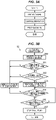
- Step S 1 the cleaning/disinfecting process
- Step S 2 cleaning/disinfection using the cleaning/disinfection liquid chemical
- Step S 3 post-cleaning for replacing the liquid chemical in the piping 3 with the dialysis water
- the cleaning/disinfecting process may be finished while leaving the liquid chemical enclosed in the piping 3 as described above, without performing the post-cleaning in Step S 3. In this case, the post-cleaning is performed before the next blood purification therapy.
- the conductivity sensor 41 used as the sensor 4 can detect the concentration of the dialysate and the absorbance sensor 42 can detect the concentration of urea nitrogen in the waste liquid.
- the cleaning/disinfection control unit 82 in the present embodiment is configured to be able to detect whether the dialysate in the piping 3 has been replaced with dialysis water at the time of the pre-cleaning in Step S 1 , based on the detection result from at least one sensor 4.
- the cleaning/disinfection control unit 82 is configured to determine whether the inside of the piping 3 has been replaced with the dialysis water based on the detection result from the sensor 4, and proceed to cleaning/disinfection in Step S 2 when it is determined that the inside of the piping 3 has been replaced with the dialysis water.
- An intended cleaning/disinfecting effect may not be obtained when the liquid chemical is introduced in the state in which the dialysate remains in the piping 3, but such a problem can be suppressed in the present embodiment.
- the cleaning/disinfection control unit 82 in the present embodiment is configured to be able to detect whether the liquid chemical in the piping 3 has been replaced with the dialysis water at the time of the post-cleaning in Step S3, based on the detection result from at least one sensor 4.
- the cleaning/disinfection control unit 82 is configured to determine whether the inside of the piping 3 has been replaced with the dialysis water based on the detection result from the sensor 4, and finish the cleaning/disinfecting process when it is determined that the inside of the piping 3 has been replaced with the dialysis water.
- the liquid chemical comes into contact with patient's blood in the next therapy and may adversely affect the blood purification therapy when the process is finished in the state in which the liquid chemical remains in the piping 3, but such a problem can be suppressed in the present embodiment.
- the control unit 8 communicates with the dialysate supply device 11 and thereby acquires information indicating the liquid chemical used in the cleaning/disinfecting process from the dialysate supply device 11 in Step S 20.
- the liquid chemical identification unit 81 specifies the liquid chemical based on the information indicating the liquid chemical and selects the sensor corresponding to the specified liquid chemical from the plural sensors 4.
- the liquid chemical identification unit 81 determines whether or not the concentration of the liquid chemical is within a predetermined reference value range by using the sensor 4 selected in Step S 20.
- the liquid chemical identification unit 81 also identifies the type of the liquid chemical through the determination made in Step S 21. That is, since the reference value range is set within a range in which the type of the liquid chemical can be identified, whether or not the type of the liquid chemical is appropriate in addition to whether or not the concentration of the liquid chemical is appropriate can be determined by determining whether or not the concentration of the liquid chemical is within the reference value range.
- Step S 20 Although the information indicating the type of the liquid chemical is acquired and the type of the liquid chemical is specified in Step S 20, it is possible to avoid cleaning/disinfection with an inappropriate type of liquid chemical even when a user puts a wrong type of liquid chemical instead of the liquid chemical which should be supplied and a liquid chemical of a different type from the controlled liquid chemical is sent from the dialysate supply device 11 due to the control since the type of the liquid chemical is identified in step S 21.
- Step S 21 When the determination made in Step S 21 is NO, the process returns to Step S 21 to repeat determination.
- the liquid chemical replacement detection unit 821 detects whether the piping 3 is filled with the liquid chemical in Step S 22. In particular, when a predetermined delay time has elapsed after the determination of YES is made in Step S 21, the liquid chemical replacement detection unit 821 detects that the piping 3 is filled with the liquid chemical.
- the determination made in Step S 22 is NO, the process returns to Step S 21.
- Step S 22 When the determination made in Step S 22 is YES, the liquid chemical flow rate control unit 822 reduces the flow rate of the liquid chemical by controlling the dual pump 5 in Step S 23. After that, in Step S 24 , whether the concentration of the liquid chemical is within the reference value range is determined based on the detection result from the sensor 4. When the determination made in Step S 24 is NO, the liquid chemical flow rate control unit 822 increases the flow rate of the liquid chemical by controlling the dual pump 5 in Step S 25 and the process then returns to Step S 21 . Step S 24 and Step S 25 can be omitted in case that, e.g., the concentration of the liquid chemical is monitored by an external device and there is no risk of a decrease in the concentration of the liquid chemical.
- Step S 24 determines, in Step S 26 , whether a preset disinfection/cleaning time has elapsed after detecting that the piping 3 is filled with the liquid chemical in Step S 22 .
- Step S 26 determines, in Step S 26 , whether a preset disinfection/cleaning time has elapsed after detecting that the piping 3 is filled with the liquid chemical in Step S 22 .
- the determination made in Step S 26 is NO, the process returns to Step S 24 .
- Step S 26 When the determination made in Step S 26 is YES, the cleaning/disinfection control unit 82 stops the flow of the liquid chemical by stopping the dual pump 5 in Step S 27. After that, it returns (proceeding to Step S 3 in FIG. 3A ).
- the example in which the information indicating the liquid chemical to be used is acquired in advance from the dialysate supply device 11 has been described.
- this process (the process in Step S 20 described above) may be omitted, and the liquid chemical may be identified by the plural sensors 4.
- the liquid chemical is identified based on the detection results from the plural sensors 4, instead of selecting the sensor to be used from the plural sensors 4 and identifying the liquid chemical based on the detection result from only this sensor.
- the blood purification device 1 may include a mechanism for preparing the dialysate or the cleaning/disinfection liquid chemical.
- the blood purification device 1 may have a built-in tank, etc., for supplying the cleaning/disinfection liquid chemical or may be supplied with the cleaning/disinfection liquid chemical from a tank, etc., which is separately provided.
- the cleaning/disinfection control unit 82 should be configured to determine whether the inside of the piping 3 has been replaced with the dialysis water at the time of the cleaning step based on the detection result from the sensor 4, and proceed to cleaning/disinfection using the next liquid chemical when it is determined that the inside of the piping 3 has been replaced with the dialysis water. It is thereby possible to further suppress mixing of the liquid chemicals.
- the piping 3 is filled with the liquid chemical based on the detection result from the sensor 4 in the present embodiment, it is not limited thereto. It is also possible to determine that the piping 3 is filled with the liquid chemical based on time elapsed since the start of liquid chemical supply. In this case, however, since the liquid chemical is not physically detected, reliability is slightly poor. That is, by determining whether the piping 3 is filled with the liquid chemical based on the detection result from the sensor 4 as in the present embodiment, it is possible to more accurately detect that the piping 3 is filled with the liquid chemical.
- the blood purification device 1 in the present embodiment is configured to be able to identify types of the liquid chemicals of at least not less than the number of the sensors 4 by using the plural sensors 4 of different detection types.
- liquid chemical flow rate control unit 822 can be omitted.
Landscapes
- Health & Medical Sciences (AREA)
- Heart & Thoracic Surgery (AREA)
- Urology & Nephrology (AREA)
- Hematology (AREA)
- Animal Behavior & Ethology (AREA)
- Engineering & Computer Science (AREA)
- Anesthesiology (AREA)
- Biomedical Technology (AREA)
- Emergency Medicine (AREA)
- Life Sciences & Earth Sciences (AREA)
- Vascular Medicine (AREA)
- General Health & Medical Sciences (AREA)
- Public Health (AREA)
- Veterinary Medicine (AREA)
- Chemical & Material Sciences (AREA)
- Chemical Kinetics & Catalysis (AREA)
- General Chemical & Material Sciences (AREA)
- External Artificial Organs (AREA)
Abstract
Description
- The invention relates to a blood purification device.
- For blood purification devices, a cleaning/disinfecting process for cleaning/disinfecting the inside of piping is performed after blood purification therapy. In the cleaning/disinfecting process, a cleaning/disinfection liquid chemical is introduced into the piping and the inside of the piping is cleaned/disinfected (see, e.g., Patent Document 1).
- Patent Document 1:
JP2014-097197A - In the cleaning/disinfecting process, different liquid chemicals are used depending on how dirty inside the piping is or how frequently the device is used, etc. Time required for cleaning/disinfection and the control details, etc., are different when using different liquid chemicals. Therefore, if, e.g., a wrong liquid chemical is used, cleaning/disinfection may be performed excessively which causes the liquid chemical to be wasted, or cleaning/disinfection may not be sufficiently performed which adversely affects the subsequent therapy.
- For example, a blood purification device into which a liquid chemical is introduced from an external device could receive data of the type of liquid chemical used from the external device by communication, etc. However, even in such a case, to further increase safety, it is desired that each blood purification device identifies the type of the actually supplied liquid chemical and determines whether the correct liquid chemical is supplied.
- Therefore, it is an object of the invention to provide a blood purification device that is capable of identifying types of cleaning/disinfection liquid chemicals and allows an appropriate cleaning/disinfecting process according to the type of liquid chemical to be performed.
- To solve the problem mentioned above, the invention according to
claim 1 provides a blood purification device for blood purification therapy performed through a blood purifier, the blood purification device comprising: - piping;
- a plurality of sensors of different detection types that are provided on the piping; and
- a liquid chemical identification unit that identifies a type of a cleaning/disinfection liquid chemical flowing through the piping by using the plurality of sensors,
- wherein the liquid chemical identification unit is configured to be able to identify types of the liquid chemicals of at least not less than the number of the plurality of sensors by using the plurality of sensors.
- The invention according to
claim 2 is the blood purification device according toclaim 1, wherein the liquid chemical identification unit selects all or part of the plurality of sensors according to the type of the liquid chemical which should be used for cleaning/disinfection and, based on detection results from the selected all or part of sensors, identifies whether or not it is a liquid chemical which should be used for the cleaning/disinfection. - The invention according to
claim 3 is the blood purification device according toclaim - The invention according to
claim 4 is the blood purification device according to any one ofclaims 1 to 3, further comprising:
a cleaning/disinfection control unit to detect whether the piping is filled with the cleaning/disinfection liquid chemical at the time of cleaning/disinfecting the piping, based on a detection result from at least one of the plurality of sensors. - The invention according to
claim 5 is the blood purification device according toclaim 4, wherein the cleaning/disinfection control unit is configured to be able to detect whether a dialysate or the liquid chemical in the piping has been replaced with dialysis water, based on a detection result from at least one of the plurality of sensors. - The invention according to
claim 6 is the blood purification device according to any one ofclaims 1 to 5, wherein the plurality of sensors comprise a conductivity sensor to measure conductivity of a liquid flowing through the piping, and an absorbance sensor to measure absorption of ultraviolet light by the liquid flowing through the piping. - The invention according to claim 7 is the blood purification device according to
claim 6, wherein the liquid chemical identification unit identifies a type of the liquid chemical by comparing a threshold for a detection value of the conductivity sensor and a threshold for a detection value of the absorbance sensor, which are set for each type of the liquid chemical, with the detection values of the conductivity sensor and the absorbance sensor. - According to the invention of
claims - According to the invention of
claim 2, it is possible to identify whether or not the liquid chemical used currently is a liquid chemical which should be used for cleaning/disinfection. - According to the invention of
claim 4, it is possible to detect whether the piping is filled with the cleaning/disinfection liquid chemical, and possible to perform an appropriate cleaning/disinfecting process. - According to the invention of
claim 5, it is possible to suppress insufficient cleaning/disinfection due to the dialysate remaining after pre-cleaning or problems in blood purification therapy due to the liquid chemical remaining after post-cleaning. - According to the invention of
claim 6, since the sensors respectively detect conductivity and absorbance, it is possible to detect liquid chemicals having different compositions and possible to identify more types of cleaning/disinfection liquid chemicals. - According to the invention of claim 7, it is possible to identify an acid cleaning solution, a peracetic acid-based disinfectant and a hypochlorite disinfectant, which are typical liquid chemicals used for the cleaning/disinfecting process.
-
-
FIG. 1 is a schematic configuration diagram illustrating a blood purification system using blood purification devices in an embodiment of the present invention. -
FIG. 2 is a schematic configuration diagram illustrating the blood purification device. -
FIG. 3A is a flowchart showing a cleaning/sterilization process. -
FIG. 3B is a flowchart of Step S2 inFIG. 3A . - An embodiment of the invention will be described below in conjunction with the appended drawings.
-
FIG. 1 is a schematic configuration diagram illustrating a blood purification system using blood purification devices in the present embodiment. As shown inFIG. 1 , ablood purification system 10 includes adialysate supply device 11 and pluralblood purification devices 1. - The
dialysate supply device 11 prepares a dialysate with a predetermined concentration using dialysis water supplied from a water treatment device (not shown) and an undiluted dialysate fluid supplied from a dissolving device (not shown), and supplies the prepared dialysate to eachblood purification device 1. The dialysate prepared by thedialysate supply device 11 is supplied to eachblood purification device 1 via adialysate supply line 12. - Each
blood purification device 1 is connected to a blood purifier (a dialyzer, not shown) for providing blood purification therapy (dialysis therapy) to a patient and supplies the dialysate supplied from thedialysate supply device 11 to the blood purifier. The details of theblood purification device 1 will be described later. - The
blood purification system 10 is configured such that thedialysate supply device 11 can communicate with eachblood purification device 1 via asignal line 13. Thedialysate supply device 11 can detect an operating status of eachblood purification device 1 and control eachblood purification device 1. The form of communication between thedialysate supply device 11 and eachblood purification device 1 is not limited thereto and may be, e.g., wireless communication instead of wired communication. - In the
blood purification system 10, a cleaning/disinfecting process for cleaning/disinfecting the inside of piping is performed after blood purification therapy. The cleaning/disinfecting process here includes a case where only cleaning is performed, a case where only disinfection is performed, and a case where both cleaning and disinfection are performed. When performing the cleaning/disinfecting process, thedialysate supply device 11 prepares a liquid chemical used for cleaning/disinfection and supplies the prepared liquid chemical to eachblood purification device 1 via thedialysate supply line 12. Thedialysate supply device 11 also has a function of notifying eachblood purification device 1 of the type, etc., of liquid chemical to be used when performing the cleaning/disinfecting process. When a worker operates thedialysate supply device 11 to start the cleaning/disinfecting process, the cleaning/disinfecting process for thedialysate supply device 11 and eachblood purification device 1 is automatically performed according to a program preset in thedialysate supply device 11. -
FIG. 2 is a schematic configuration diagram illustrating theblood purification device 1.FIG. 2 schematically shows piping arrangement during cleaning/disinfection. As shown inFIG. 2 , theblood purification device 1 has a pair ofconnectors 2a, 2b to which the blood purifier (not shown) is connected. During cleaning/disinfection, the twoconnectors 2a, 2b are connected via abypass connector 2c. -
Piping 3 inside theblood purification device 1 has a supply-side flow path 31 including aliquid supply port 3a connected to thedialysate supply line 12 and theconnector 2a, and a discharge-side flow path 32 including the other connector 2b and aliquid discharge port 3b. - The
blood purification device 1 also has adual pump 5 which is configured to operate so that an amount of liquid supplied to the blood purifier and an amount of liquid discharged from the blood purifier are mechanically equivalent. In the present embodiment, thedual pump 5 is used to control a flow rate of the liquid flowing through thepiping 3. In addition, a removedwater flow path 33 is provided on the discharge-side flow path 32 so as to bypass thedual pump 5, and awater removal pump 6 to control an amount of water removed from blood is provided on the removedwater flow path 33. In addition, a liquid supply valve 7 composed of a solenoid valve capable of shutting off liquid supply is provided on the supply-side flow path 31. The configuration diagram inFIG. 2 is simplified, and a flow path for bypassing each part, a solenoid valve, a filter unit, a pressure sensor for measuring liquid pressure, a temperature sensor for measuring liquid temperature, etc., may be appropriately provided. - The
blood purification device 1 also includes acontrol device 8 that controls thedual pump 5, thewater removal pump 6, the liquid supply valve 7, etc. Thecontrol device 8 controls each part during blood purification therapy or during cleaning/disinfection. - The
blood purification device 1 in the present embodiment includes plural sensors of different detection types provided on thepiping 3 inside the device, and a liquidchemical identification unit 81 that identifies a type of cleaning/disinfection liquid chemical flowing through thepiping 3 by using theplural sensors 4. - The
plural sensors 4 are provided on thepiping 3 and can detect that a cleaning/disinfection liquid chemical is flowing through thepiping 3. In the present embodiment, theseplural sensors 4 are used to determine the type of the cleaning/disinfection liquid chemical. In the present embodiment, aconductivity sensor 41 to measure conductivity of a liquid flowing through thepiping 3 and anabsorbance sensor 42 to measure absorption of ultraviolet light in the 280-nm band by the liquid flowing through thepiping 3 are used as theplural sensors 4. However, thesensors 4 are not limited thereto, and, e.g., a pH sensor to measure pH of the liquid flowing through thepipe 3, etc., may be included. - The
conductivity sensor 41 is used to monitor a dialysate concentration during blood purification therapy and is provided on the supply-side flow path 31. When the dialysate concentration exceeds a threshold during blood purification therapy, an alarm is issued and is visually or audibly notified via a user interface, such as a display unit (not shown). Meanwhile, theabsorbance sensor 42 is used to measure absorbance of waste liquid from the blood purifier, detect an amount of urea nitrogen contained in the waste liquid and monitor the progress of dialysis during blood purification therapy, and is provided on the discharge-side flow path 32. That is, in the present embodiment, theconductivity sensor 41 and theabsorbance sensor 42, which are conventionally used in blood purification therapy, are used for a different purpose and are used to determine the type of cleaning/disinfection liquid chemical. As a result, it is not necessary to separately provide a sensor for determining the type of cleaning/disinfection liquid chemical, the system configuration is simplified, and it is possible to reduce the cost. - Typical liquid chemicals used for cleaning/disinfection include an acid cleaning solution, a peracetic acid-based disinfectant and a hypochlorite disinfectant. Of those, the acid cleaning solution and the hypochlorite disinfectant have different conductivities from that of the dialysis water and thus can be detected by the
conductivity sensor 41. Meanwhile, of the liquid chemicals mentioned above, the peracetic acid-based disinfectant and the hypochlorite disinfectant exhibit different UV absorbances (ultraviolet light in the 280-nm band) from that of the dialysis water and thus can be detected by theabsorbance sensor 42. As such, in the present embodiment, two or more types (three types in this example) of liquid chemicals can be detected by using twosensors 4. - Since conductivity detected by the
conductivity sensor 41 and absorbance detected by theabsorbance sensor 42 depend on the concentration of the liquid chemical flowing through thepiping 3, the concentration of the liquid chemical can also be detected by detecting conductivity or absorbance. That is, in the present embodiment, thesensors 4 are configured to be able to detect the concentration of the liquid chemical flowing through thepiping 3. - The liquid
chemical identification unit 81 is mounted on thecontrol device 8 and is realized by appropriately combining an arithmetic element such as CPU, a storage device such as memory, a software, and an interface, etc. The liquidchemical identification unit 81 is configured to be able to identify types of the liquid chemicals of at least not less than the number of thesensors 4 based on detection results from theplural sensors 4. In the present embodiment, the liquidchemical identification unit 81 is configured to be able to identify types of the liquid chemicals of more than the number of theplural sensors 4 based on a combination of the detection results from theplural sensors 4. - In more particular, the liquid
chemical identification unit 81 identifies the type of the liquid chemical by comparing a threshold (within a reference value range) for a detection value of theconductivity sensor 41 and a threshold (within a reference value range) for a detection value of theabsorbance sensor 42, which are set for each type of liquid chemical, with the detection values of theconductivity sensor 41 and theabsorbance sensor 42. For example, when the detection values of theconductivity sensor 41 and theabsorbance sensor 42 are respectively within the reference value ranges for an acid cleaning solution, it is identified that the liquid chemical is the acid cleaning solution. However, it is not limited thereto. Based the detection results from theconductivity sensor 41 and theabsorbance sensor 42, the liquidchemical identification unit 81 may identify that the liquid chemical is the acid cleaning solution when only the detection value of theconductivity sensor 41 changes as compared to measurement result of the dialysis water (when the amount of change is not less than a predetermined threshold), the liquid chemical is the peracetic acid-based disinfectant when only the detection value of theabsorbance sensor 42 changes (when the amount of change is not less than a predetermined threshold), and the liquid chemical is the hypochlorite disinfectant when the detection values of theconductivity sensor 41 and theabsorbance sensor 42 both change (when the amount of change is not less than a predetermined threshold). - In the present embodiment, the
control device 8 is configured to communicate with thedialysate supply device 11 and acquire information indicating the liquid chemical used in the cleaning/disinfecting process from thedialysate supply device 11. The liquidchemical identification unit 81 is configured to specify the liquid chemical based on the acquired information indicating the liquid chemical and select the sensor corresponding to the specified liquid chemical from theplural sensors 4. - As such, in the present embodiment, the liquid
chemical identification unit 81 selects all or part of theplural sensors 4 according to the type of the liquid chemical which should be used for cleaning/disinfection. The liquidchemical identification unit 81 is also configured to identify whether or not the liquid chemical used currently is a liquid chemical which should be used for cleaning/disinfection, based on the detection results from the selected all or part ofsensors 4. The reference value ranges mentioned above are set within a range in which the type of the liquid chemical can be identified. Therefore, by determining whether or not the concentration of the liquid chemical is within the reference value range, it is possible to determine whether or not the type of the liquid chemical is appropriate in addition to whether or not the concentration of the liquid chemical is appropriate. As a result, it is possible to avoid cleaning/disinfection with an inappropriate type of liquid chemical even when a user puts a wrong type of liquid chemical instead of the liquid chemical which should be supplied and a liquid chemical of a different type from the controlled liquid chemical is sent from thedialysate supply device 11 due to the control. - The
blood purification device 1 also includes a cleaning/disinfection control unit 82 to cause the cleaning/disinfection liquid chemical to flow through thepiping 3 inside the device and perform the cleaning/disinfecting process for thepiping 3. The cleaning/disinfection control unit 82 performs the cleaning/disinfecting process according to the instruction from thedialysate supply device 11. The cleaning/disinfection control unit 82 is mounted on thecontrol device 8 and is realized by appropriately combining an arithmetic element such as CPU, a storage device such as memory, a software, and an interface, etc. The cleaning/disinfection control unit 82 has a liquid chemicalreplacement detection unit 821 and a liquid chemical flowrate control unit 822. - The liquid chemical
replacement detection unit 821 is configured to detect, during cleaning/disinfecting thepiping 3, that thepiping 3 is filled with the cleaning/disinfection liquid chemical (the other liquid is replaced with the liquid chemical), based on the detection result from at least onesensor 4. The liquid chemicalreplacement detection unit 821 uses the detection result from thesensor 4 corresponding to the liquid chemical identified by the liquidchemical identification unit 81, compares the detection value of thesensor 4 with the threshold corresponding to the identified liquid chemical, and thereby detects that the liquid chemical is flowing through thepiping 3 at a position where thesensor 4 is provided. In other words, when the concentration of the liquid chemical detected by thesensor 4 exceeds a predetermined reference value, the liquid chemicalreplacement detection unit 821 detects that the liquid chemical is flowing through thepiping 3 at the position where thesensor 4 is provided. - When the liquid
chemical identification unit 81 identifies that the liquid chemical used is, e.g., an acid cleaning solution, the liquid chemicalreplacement detection unit 821 compares the detection value of theconductivity sensor 41 with a preset threshold for the acid cleaning solution and detects that the liquid chemical is flowing through thepiping 3 at the position where theconductivity sensor 41 is provided. In case of the hypochlorite disinfectant, the flow of the liquid chemical may be detected by using only one of theconductivity sensor 41 and theabsorbance sensor 42 or the flow of the liquid chemical may be detected by using bothsensors - During cleaning/disinfection, the
entire piping 3 including the downstream side of thesensor 4 need to be filled with the liquid chemical. Therefore, when a delay time preset according to a piping capacity of thepiping 3 on the downstream side of thesensor 4 used to detect flow of a liquid chemical has elapsed after detection of the flow of the liquid chemical, the liquid chemicalreplacement detection unit 821 detects that thepiping 3 is filled with the cleaning/disinfection liquid chemical. For example, in case that theconductivity sensor 41 detects the liquid chemical, the delay time is set longer since it is arranged on the upstream side of theabsorbance sensor 42 in a direction of sending the liquid chemical. - As such, the threshold (the reference value of the concentration) for detection of the flow of the liquid chemical and length of the delay time are different depending on the liquid chemical to be used. By providing the liquid
chemical identification unit 81, it is possible to perform an appropriate cleaning/disinfecting process according to the type of the liquid chemical actually used even when there is a human error such as, e.g., using a liquid chemical which is different from the intended liquid chemical. The liquidchemical identification unit 81 may be configured to issue an alarm by, e.g., sending an alert signal to thedialysate supply device 11 when the liquid chemical notified by thedialysate supply device 11 is different from the identified liquid chemical. - When the liquid chemical
replacement detection unit 821 detects that thepiping 3 is filled with the liquid chemical, the liquid chemical flowrate control unit 822 performs a process of reducing a flow rate of the liquid chemical as compared with that before the detection. In the present embodiment, the liquid chemical flowrate control unit 822 is configured to control the flow rate of the liquid chemical by controlling thedual pump 5. - As a result of study, the present inventors found that a cleaning/disinfecting effect is dominant during when the liquid chemical is in contact with the
piping 3 and a sufficient cleaning/disinfecting effect is obtained even if the flow rate of the liquid chemical is reduced. However, to efficiently perform the cleaning/disinfecting process in a short time, the flow rate of the liquid chemical is desirably as high as possible until thepiping 3 is filled with the liquid chemical. Therefore, in the present embodiment, the flow rate of the liquid chemical is reduced after thepiping 3 is filled with the liquid chemical, thereby reducing the use amount of the liquid chemical while maintaining the sufficient cleaning/disinfecting effect. - To shorten the time required for the cleaning/disinfecting process, the flow rate of the liquid chemical before the
piping 3 is filled with the liquid chemical is desirably as high as possible. Meanwhile, to reduce the use amount of the liquid chemical, the flow rate of the liquid chemical after thepiping 3 is filled with the liquid chemical is desirably as low as possible. Thus, the flow rate of the liquid chemical after thepiping 3 is filled with the liquid chemical is desirably not more than 1/2, more preferably not more than 1/4, of the flow rate of the liquid chemical before thepiping 3 is filled with the liquid chemical. In this regard, however, if the flow rate of the liquid chemical after thepiping 3 is filled with the liquid chemical is excessively reduced, dirt, etc., is less likely to be washed away and the cleaning/disinfecting effect may decrease. Therefore, the flow rate of the liquid chemical after thepiping 3 is filled with the liquid chemical should be set taking into account the piping capacity, etc., so that the cleaning/disinfecting effect can be maintained. - The cleaning/
disinfection control unit 82 is configured to determine that cleaning/disinfection with the liquid chemical has been finished, to stop thedual pump 5 and to proceed to the next step (a post-cleaning (described later), etc.), when a predetermined disinfection/cleaning time has elapsed after detecting that thepiping 3 is filled with the liquid chemical. In this regard, after the disinfection/cleaning time has elapsed, the cleaning/disinfecting process may be finished in the state in which thedual pump 5 is stopped and the cleaning/disinfection liquid chemical is enclosed in thepiping 3. The disinfection/cleaning time may be set for each liquid chemical to be used. To sufficiently clean/disinfect the solenoid valve such as the liquid supply valve 7, the cleaning/disinfection control unit 82 should control to open and close the solenoid valve at predetermined time intervals from when detecting that thepiping 3 is filled with the liquid chemical to when the predetermined disinfection/cleaning time elapses. - When the concentration of the liquid chemical decreases for some reason (e.g., insufficient liquid chemical, etc.) before the disinfection/cleaning time elapses after detecting that the
piping 3 is filled with the liquid chemical, a sufficient cleaning/disinfecting effect may not be obtained. Thus, the cleaning/disinfection control unit 82 may be configured to increase the flow rate of the liquid chemical by the liquid chemical flowrate control unit 822 and detect whether thepiping 3 is filled with the liquid chemical by the liquid chemicalreplacement detection unit 821 again when the liquid chemicalreplacement detection unit 821 detects that the concentration of the liquid chemical is below the reference value (when the detection value of thesensor 4 is below the threshold) before the disinfection/cleaning time elapses after detecting that thepiping 3 is filled with the liquid chemical. As a result, even if the concentration of the liquid chemical decreases during cleaning/disinfection for some reason, it is possible to prevent the process from being finished without sufficient cleaning/disinfection. In addition, the cleaning/disinfection control unit 82 may be configured to issue an alarm by, e.g., sending an alert signal to thedialysate supply device 11 when a decrease in the concentration of the liquid chemical is detected. - Now, the procedure of the cleaning/disinfecting process will be described using
FIGS. 3A and 3B . When the cleaning/disinfecting process is started, the dialysate for blood purification therapy remains in thepiping 3. Thus, in the cleaning/disinfecting process, pre-cleaning for replacing the dialysate in thepiping 3 with the dialysis water is firstly performed in Step S1, as shown inFIG. 3A . After that, cleaning/disinfection using the cleaning/disinfection liquid chemical is performed in Step S2. After that, post-cleaning for replacing the liquid chemical in thepiping 3 with the dialysis water is performed in Step S3. Alternatively, the cleaning/disinfecting process may be finished while leaving the liquid chemical enclosed in thepiping 3 as described above, without performing the post-cleaning in Step S3. In this case, the post-cleaning is performed before the next blood purification therapy. - As described previously, the
conductivity sensor 41 used as thesensor 4 can detect the concentration of the dialysate and theabsorbance sensor 42 can detect the concentration of urea nitrogen in the waste liquid. Thus, by monitoring the detection values of theconductivity sensor 41 and theabsorbance sensor 42, it is possible to detect whether the dialysate (including the waste liquid) in thepiping 3 has been replaced with the dialysis water at the time of the pre-cleaning. Therefore, the cleaning/disinfection control unit 82 in the present embodiment is configured to be able to detect whether the dialysate in thepiping 3 has been replaced with dialysis water at the time of the pre-cleaning in Step S1, based on the detection result from at least onesensor 4. The cleaning/disinfection control unit 82 is configured to determine whether the inside of thepiping 3 has been replaced with the dialysis water based on the detection result from thesensor 4, and proceed to cleaning/disinfection in Step S2 when it is determined that the inside of thepiping 3 has been replaced with the dialysis water. An intended cleaning/disinfecting effect may not be obtained when the liquid chemical is introduced in the state in which the dialysate remains in thepiping 3, but such a problem can be suppressed in the present embodiment. - In addition, since the concentration of the cleaning/disinfection liquid chemical can be detected by the
sensors 4, whether the liquid chemical in thepiping 3 has been replaced with the dialysis water can be detected at the time of post-cleaning by monitoring the detection values of thesensors 4. Therefore, the cleaning/disinfection control unit 82 in the present embodiment is configured to be able to detect whether the liquid chemical in thepiping 3 has been replaced with the dialysis water at the time of the post-cleaning in Step S3, based on the detection result from at least onesensor 4. The cleaning/disinfection control unit 82 is configured to determine whether the inside of thepiping 3 has been replaced with the dialysis water based on the detection result from thesensor 4, and finish the cleaning/disinfecting process when it is determined that the inside of thepiping 3 has been replaced with the dialysis water. The liquid chemical comes into contact with patient's blood in the next therapy and may adversely affect the blood purification therapy when the process is finished in the state in which the liquid chemical remains in thepiping 3, but such a problem can be suppressed in the present embodiment. - As shown in
FIG. 3B , in cleaning/disinfection in Step S2, firstly, thecontrol unit 8 communicates with thedialysate supply device 11 and thereby acquires information indicating the liquid chemical used in the cleaning/disinfecting process from thedialysate supply device 11 in Step S20. Subsequently, the liquidchemical identification unit 81 specifies the liquid chemical based on the information indicating the liquid chemical and selects the sensor corresponding to the specified liquid chemical from theplural sensors 4. - After that, in Step S21, the liquid
chemical identification unit 81 determines whether or not the concentration of the liquid chemical is within a predetermined reference value range by using thesensor 4 selected in Step S20. The liquidchemical identification unit 81 also identifies the type of the liquid chemical through the determination made in Step S21. That is, since the reference value range is set within a range in which the type of the liquid chemical can be identified, whether or not the type of the liquid chemical is appropriate in addition to whether or not the concentration of the liquid chemical is appropriate can be determined by determining whether or not the concentration of the liquid chemical is within the reference value range. Furthermore, although the information indicating the type of the liquid chemical is acquired and the type of the liquid chemical is specified in Step S20, it is possible to avoid cleaning/disinfection with an inappropriate type of liquid chemical even when a user puts a wrong type of liquid chemical instead of the liquid chemical which should be supplied and a liquid chemical of a different type from the controlled liquid chemical is sent from thedialysate supply device 11 due to the control since the type of the liquid chemical is identified in step S21. - When the determination made in Step S21 is NO, the process returns to Step S21 to repeat determination. When the determination made in Step S21 is YES, the liquid chemical
replacement detection unit 821 detects whether thepiping 3 is filled with the liquid chemical in Step S22. In particular, when a predetermined delay time has elapsed after the determination of YES is made in Step S21, the liquid chemicalreplacement detection unit 821 detects that thepiping 3 is filled with the liquid chemical. When the determination made in Step S22 is NO, the process returns to Step S21. - When the determination made in Step S22 is YES, the liquid chemical flow
rate control unit 822 reduces the flow rate of the liquid chemical by controlling the dual pump 5in Step S23. After that, in Step S24, whether the concentration of the liquid chemical is within the reference value range is determined based on the detection result from thesensor 4. When the determination made in Step S24 is NO, the liquid chemical flowrate control unit 822 increases the flow rate of the liquid chemical by controlling thedual pump 5 in Step S25 and the process then returns to Step S21. Step S24 and Step S25 can be omitted in case that, e.g., the concentration of the liquid chemical is monitored by an external device and there is no risk of a decrease in the concentration of the liquid chemical. - When the determination made in Step S24 is YES, the cleaning/
disinfection control unit 82 determines, in Step S26, whether a preset disinfection/cleaning time has elapsed after detecting that thepiping 3 is filled with the liquid chemical in Step S22. When the determination made in Step S26 is NO, the process returns to Step S24. - When the determination made in Step S26 is YES, the cleaning/
disinfection control unit 82 stops the flow of the liquid chemical by stopping thedual pump 5 in Step S27. After that, it returns (proceeding to Step S3 inFIG. 3A ). - In the present embodiment, the example in which the information indicating the liquid chemical to be used is acquired in advance from the
dialysate supply device 11 has been described. However, this process (the process in Step S20 described above) may be omitted, and the liquid chemical may be identified by theplural sensors 4. In this case, preferably, all of theplural sensors 4 are used and the liquid chemical is identified based on the detection results from theplural sensors 4, instead of selecting the sensor to be used from theplural sensors 4 and identifying the liquid chemical based on the detection result from only this sensor. - Although the
blood purification device 1 supplied with the dialysate or the cleaning/disinfection liquid chemical from the externaldialysate supply device 11 has been described in the present embodiment, theblood purification device 1 may include a mechanism for preparing the dialysate or the cleaning/disinfection liquid chemical. Alternatively, theblood purification device 1 may have a built-in tank, etc., for supplying the cleaning/disinfection liquid chemical or may be supplied with the cleaning/disinfection liquid chemical from a tank, etc., which is separately provided. - In addition, although the description is omitted in
FIG. 3A , it is obviously possible to continuously perform cleaning/sterilization using different liquid chemicals such as, e.g., performing cleaning/sterilization using a disinfectant in a low oxidation after cleaning/sterilization using an acid cleaning solution. In this case, it is desirable to prevent mixing of the liquid chemicals by performing the pre-cleaning to replace the inside of thepiping 3 with the dialysis water after finishing cleaning/sterilization with a given liquid chemical, and then performing cleaning/sterilization with another liquid chemical. This is because if different liquid chemicals are mixed, a toxic substance such as chlorine gas may be produced depending on a combination of the liquid chemicals. In such a case, the cleaning/disinfection control unit 82 should be configured to determine whether the inside of thepiping 3 has been replaced with the dialysis water at the time of the cleaning step based on the detection result from thesensor 4, and proceed to cleaning/disinfection using the next liquid chemical when it is determined that the inside of thepiping 3 has been replaced with the dialysis water. It is thereby possible to further suppress mixing of the liquid chemicals. - Furthermore, although it is detected that the
piping 3 is filled with the liquid chemical based on the detection result from thesensor 4 in the present embodiment, it is not limited thereto. It is also possible to determine that thepiping 3 is filled with the liquid chemical based on time elapsed since the start of liquid chemical supply. In this case, however, since the liquid chemical is not physically detected, reliability is slightly poor. That is, by determining whether thepiping 3 is filled with the liquid chemical based on the detection result from thesensor 4 as in the present embodiment, it is possible to more accurately detect that thepiping 3 is filled with the liquid chemical. - As described above, the
blood purification device 1 in the present embodiment is configured to be able to identify types of the liquid chemicals of at least not less than the number of thesensors 4 by using theplural sensors 4 of different detection types. - For example, in case of using one sensor, it is difficult to determine typical liquid chemicals used for the cleaning/disinfecting process. If, e.g., a very expensive and large-scale equipment such as a spectrophotometer is used, it is possible to determine the liquid chemical by one equipment, but it is not realistic. When using
plural sensors 4 of different detection types as in the present embodiment, it is possible to determine the typical liquid chemicals used for the cleaning/disinfecting process by using thesensors 4 which are relatively inexpensive and conventionally used for monitoring blood purification therapy. That is, in the present embodiment, it is possible to identify many types of cleaning/disinfection liquid chemicals with an inexpensive and simple system configuration and possible to perform an appropriate cleaning/disinfecting process according to the type of the liquid chemical. - Technical ideas understood from the embodiment will be described below citing the reference numerals, etc., used for the embodiment. However, each reference numeral, etc., described below is not intended to limit the constituent elements in the claims to the members, etc., specifically described in the embodiment.
- [1] A blood purification device (1) for blood purification therapy performed through a blood purifier, the blood purification device (1) comprising: piping (3); a plurality of sensors (4) of different detection types that are provided on the piping (3); and a liquid chemical identification unit (81) that identifies a type of a cleaning/disinfection liquid chemical flowing through the piping (3) by using the plurality of sensors (4), wherein the liquid chemical identification unit (81) is configured to be able to identify types of the liquid chemicals of at least not less than the number of the plurality of sensors (4) by using the plurality of sensors (4).
- [2] The blood purification device described in [1], wherein the liquid chemical identification unit (81) selects all or part of the plurality of sensors (4) according to the type of the liquid chemical which should be used for cleaning/disinfection and, based on detection results from the selected all or part of sensors (4), identifies whether or not it is a liquid chemical which should be used for the cleaning/disinfection.
- [3] The blood purification device (1) described in [1] or [2], wherein the liquid chemical identification unit (81) is configured to be able to identify types of the liquid chemicals of more than the number of the plurality of sensors (4) based on a combination of the detection results from the plurality of sensors (4).
- [4] The blood purification device (1) described in any one of [1] to [3], comprising: a cleaning/disinfection control unit (82) to detect whether the piping (3) is filled with the cleaning/disinfection liquid chemical at the time of cleaning/disinfecting the piping (3), based on a detection result from at least one of the plurality of sensors (4).
- [5] The blood purification device (1) described in [4], wherein the cleaning/disinfection control unit (82) is configured to be able to detect whether a dialysate or the liquid chemical in the piping (3) has been replaced with dialysis water, based on a detection result from at least one of the plurality of sensors (4).
- [6] The blood purification device (1) described in any one of [1] to [5], wherein the plurality of sensors (4) comprise a conductivity sensor (4) to measure conductivity of a liquid flowing through the piping (3), and an absorbance sensor (42) to measure absorption of ultraviolet light by the liquid flowing through the piping (3).
- [7] The blood purification device (1) described in [6], wherein the liquid chemical identification unit (81) identifies the type of the liquid chemical by comparing a threshold for a detection value of the conductivity sensor (41) and a threshold for a detection value of the absorbance sensor (42), which are set for each type of the liquid chemical, with the detection values of the conductivity sensor (41) and the absorbance sensor (42).
- Although the embodiment of the invention has been described, the invention according to claims is not to be limited the embodiment described above. In addition, not all combinations of the features described in the embodiment are necessary to solve the problem of the invention.
- In addition, the invention can be appropriately modified and implemented without departing from the gist thereof. For example, although the example in which the liquid chemical flow
rate control unit 822 is provided has been described in the embodiment, the liquid chemical flowrate control unit 822 can be omitted. -
- 1:
- blood purification device
- 3:
- piping
- 4:
- sensor
- 41:
- conductivity sensor
- 42:
- absorbance sensor
- 5:
- dual pump
- 8:
- control device
- 81:
- liquid chemical identification unit
- 82:
- cleaning/disinfection control unit
- 821:
- liquid chemical replacement detection unit
- 822:
- liquid chemical flow rate control unit
Claims (7)
- A blood purification device for blood purification therapy performed through a blood purifier, the blood purification device comprising:piping;a plurality of sensors of different detection types that are provided on the piping; anda liquid chemical identification unit that identifies a type of a cleaning/disinfection liquid chemical flowing through the piping by using the plurality of sensors,wherein the liquid chemical identification unit is configured to be able to identify types of the liquid chemicals of at least not less than the number of the plurality of sensors by using the plurality of sensors.
- The blood purification device according to claim 1, wherein the liquid chemical identification unit selects all or part of the plurality of sensors according to the type of the liquid chemical which should be used for cleaning/disinfection and, based on detection results from the selected all or part of sensors, identifies whether or not it is a liquid chemical which should be used for the cleaning/disinfection.
- The blood purification device according to claim 1 or 2, wherein the liquid chemical identification unit is configured to be able to identify types of the liquid chemicals of more than the number of the plurality of sensors based on a combination of the detection results from the plurality of sensors.
- The blood purification device according to any one of claims 1 to 3, comprising:
a cleaning/disinfection control unit to detect whether the piping is filled with the cleaning/disinfection liquid chemical at the time of cleaning/disinfecting the piping, based on a detection result from at least one of the plurality of sensors. - The blood purification device according to claim 4, wherein the cleaning/disinfection control unit is configured to be able to detect whether a dialysate or the liquid chemical in the piping has been replaced with dialysis water, based on a detection result from at least one of the plurality of sensors.
- The blood purification device according to any one of claims 1 to 5, wherein the plurality of sensors comprise a conductivity sensor to measure conductivity of a liquid flowing through the piping, and an absorbance sensor to measure absorption of ultraviolet light by the liquid flowing through the piping.
- The blood purification device according to claim 6, wherein the liquid chemical identification unit identifies the type of the liquid chemical by comparing a threshold for a detection value of the conductivity sensor and a threshold for a detection value of the absorbance sensor, which are set for each type of the liquid chemical, with the detection values of the conductivity sensor and the absorbance sensor.
Applications Claiming Priority (3)
| Application Number | Priority Date | Filing Date | Title |
|---|---|---|---|
| JP2019097205 | 2019-05-23 | ||
| JP2019102813A JP7262310B2 (en) | 2019-05-23 | 2019-05-31 | blood purifier |
| PCT/JP2020/018464 WO2020235340A1 (en) | 2019-05-23 | 2020-05-01 | Blood purification device |
Publications (3)
| Publication Number | Publication Date |
|---|---|
| EP3974008A1 true EP3974008A1 (en) | 2022-03-30 |
| EP3974008A4 EP3974008A4 (en) | 2023-01-18 |
| EP3974008B1 EP3974008B1 (en) | 2025-10-29 |
Family
ID=73458095
Family Applications (1)
| Application Number | Title | Priority Date | Filing Date |
|---|---|---|---|
| EP20810584.1A Active EP3974008B1 (en) | 2019-05-23 | 2020-05-01 | Blood purification device |
Country Status (5)
| Country | Link |
|---|---|
| US (2) | US12318518B2 (en) |
| EP (1) | EP3974008B1 (en) |
| JP (1) | JP7442715B2 (en) |
| CN (1) | CN113874053B (en) |
| WO (1) | WO2020235340A1 (en) |
Family Cites Families (14)
| Publication number | Priority date | Publication date | Assignee | Title |
|---|---|---|---|---|
| US4332264A (en) * | 1980-03-03 | 1982-06-01 | United Healthcare Association | Automated cleaning system for dialyzers |
| JP2515944Y2 (en) * | 1990-02-05 | 1996-11-06 | 株式会社三陽電機製作所 | Hemodialysis machine |
| JPH105764A (en) * | 1996-06-24 | 1998-01-13 | Kinousui Kenkyusho:Kk | Production of acidic electrolyzed water and acidic electrolyzed water |
| DE19747360B8 (en) * | 1997-10-27 | 2007-05-16 | Fresenius Medical Care De Gmbh | Method for measuring performance parameters of mass and energy exchange modules |
| JP3101956U (en) | 2003-11-28 | 2004-06-24 | 株式会社エムテック | Work table equipment for aerial work bucket |
| JP2010000207A (en) * | 2008-06-19 | 2010-01-07 | Dkk Toa Corp | Dialysate discriminating method in dialysate piping, and dialysate feeding system |
| JP5483741B2 (en) * | 2011-06-01 | 2014-05-07 | 日機装株式会社 | Blood purification system |
| JP5369140B2 (en) * | 2011-06-08 | 2013-12-18 | 日機装株式会社 | Mixing equipment |
| DE102012109858A1 (en) | 2012-10-16 | 2014-04-17 | B. Braun Avitum Ag | Dialysis optimization methods |
| JP5734262B2 (en) | 2012-11-14 | 2015-06-17 | 日機装株式会社 | Blood purification system |
| DE102013103221A1 (en) | 2013-03-28 | 2014-10-02 | B. Braun Avitum Ag | Method for detecting recirculation in an arteriovenous shunt during ongoing hemodialysis and dialysis |
| JP6545485B2 (en) | 2015-03-10 | 2019-07-17 | 日機装株式会社 | Blood purification device |
| JP7129757B2 (en) * | 2016-03-31 | 2022-09-02 | 旭化成メディカル株式会社 | Blood purification device and sterilization method |
| JP6998112B2 (en) | 2016-09-12 | 2022-01-18 | 日機装株式会社 | Blood purification device |
-
2020
- 2020-05-01 WO PCT/JP2020/018464 patent/WO2020235340A1/en not_active Ceased
- 2020-05-01 EP EP20810584.1A patent/EP3974008B1/en active Active
- 2020-05-01 CN CN202080037750.XA patent/CN113874053B/en active Active
- 2020-05-01 US US17/610,295 patent/US12318518B2/en active Active
-
2023
- 2023-04-11 JP JP2023064032A patent/JP7442715B2/en active Active
-
2025
- 2025-05-07 US US19/201,127 patent/US20250262363A1/en active Pending
Also Published As
| Publication number | Publication date |
|---|---|
| CN113874053B (en) | 2024-12-06 |
| JP2023080181A (en) | 2023-06-08 |
| US12318518B2 (en) | 2025-06-03 |
| EP3974008A4 (en) | 2023-01-18 |
| WO2020235340A1 (en) | 2020-11-26 |
| EP3974008B1 (en) | 2025-10-29 |
| US20220211924A1 (en) | 2022-07-07 |
| JP7442715B2 (en) | 2024-03-04 |
| US20250262363A1 (en) | 2025-08-21 |
| CN113874053A (en) | 2021-12-31 |
Similar Documents
| Publication | Publication Date | Title |
|---|---|---|
| US12397094B2 (en) | Water treatment systems, devices, and methods for fluid preparation | |
| JP5734262B2 (en) | Blood purification system | |
| TW201808350A (en) | Apparatus and method for measuring the concentration of a disinfectant in a medical device reprocessing system | |
| JP2010000207A (en) | Dialysate discriminating method in dialysate piping, and dialysate feeding system | |
| US9420943B2 (en) | Endoscope reprocessing apparatus | |
| TW201827087A (en) | Dynamic disinfectant administration with concentrate degradation compensation | |
| JP2008526375A (en) | Purification system for solution preparation for medical applications | |
| KR20160112229A (en) | Smart chloration system | |
| US20250262363A1 (en) | Blood Purification Device | |
| CN107261236A (en) | Blood purification device and sterilization method | |
| JP6159771B2 (en) | Blood purification equipment | |
| JP7262310B2 (en) | blood purifier | |
| JP4087647B2 (en) | Extracorporeal blood treatment apparatus and method for detecting impurities in washing liquid for washing out extracorporeal blood treatment apparatus | |
| CN107660160B (en) | Zirconium phosphate and zirconium oxide recharger control logic and operating process algorithm | |
| JP7229099B2 (en) | blood purifier | |
| JP6668171B2 (en) | Blood purification system | |
| JP6897380B2 (en) | Water treatment system | |
| JP6171455B2 (en) | Dialysate supply device | |
| JP6135231B2 (en) | Dialysate supply device | |
| JP6490493B2 (en) | Blood purification system | |
| JP2020192288A (en) | Chemical supply device and blood purification system |
Legal Events
| Date | Code | Title | Description |
|---|---|---|---|
| STAA | Information on the status of an ep patent application or granted ep patent |
Free format text: STATUS: THE INTERNATIONAL PUBLICATION HAS BEEN MADE |
|
| PUAI | Public reference made under article 153(3) epc to a published international application that has entered the european phase |
Free format text: ORIGINAL CODE: 0009012 |
|
| STAA | Information on the status of an ep patent application or granted ep patent |
Free format text: STATUS: REQUEST FOR EXAMINATION WAS MADE |
|
| 17P | Request for examination filed |
Effective date: 20211118 |
|
| AK | Designated contracting states |
Kind code of ref document: A1 Designated state(s): AL AT BE BG CH CY CZ DE DK EE ES FI FR GB GR HR HU IE IS IT LI LT LU LV MC MK MT NL NO PL PT RO RS SE SI SK SM TR |
|
| DAV | Request for validation of the european patent (deleted) | ||
| DAX | Request for extension of the european patent (deleted) | ||
| A4 | Supplementary search report drawn up and despatched |
Effective date: 20221219 |
|
| RIC1 | Information provided on ipc code assigned before grant |
Ipc: A61M 1/16 20060101AFI20221213BHEP |
|
| P01 | Opt-out of the competence of the unified patent court (upc) registered |
Effective date: 20230523 |
|
| STAA | Information on the status of an ep patent application or granted ep patent |
Free format text: STATUS: EXAMINATION IS IN PROGRESS |
|
| 17Q | First examination report despatched |
Effective date: 20241217 |
|
| GRAP | Despatch of communication of intention to grant a patent |
Free format text: ORIGINAL CODE: EPIDOSNIGR1 |
|
| STAA | Information on the status of an ep patent application or granted ep patent |
Free format text: STATUS: GRANT OF PATENT IS INTENDED |
|
| INTG | Intention to grant announced |
Effective date: 20250530 |
|
| GRAS | Grant fee paid |
Free format text: ORIGINAL CODE: EPIDOSNIGR3 |
|
| GRAA | (expected) grant |
Free format text: ORIGINAL CODE: 0009210 |
|
| STAA | Information on the status of an ep patent application or granted ep patent |
Free format text: STATUS: THE PATENT HAS BEEN GRANTED |
|
| AK | Designated contracting states |
Kind code of ref document: B1 Designated state(s): AL AT BE BG CH CY CZ DE DK EE ES FI FR GB GR HR HU IE IS IT LI LT LU LV MC MK MT NL NO PL PT RO RS SE SI SK SM TR |
|
| REG | Reference to a national code |
Ref country code: CH Ref legal event code: F10 Free format text: ST27 STATUS EVENT CODE: U-0-0-F10-F00 (AS PROVIDED BY THE NATIONAL OFFICE) Effective date: 20251029 Ref country code: GB Ref legal event code: FG4D |
|
| REG | Reference to a national code |
Ref country code: DE Ref legal event code: R096 Ref document number: 602020061321 Country of ref document: DE |
|
| REG | Reference to a national code |
Ref country code: IE Ref legal event code: FG4D |
|
| REG | Reference to a national code |
Ref country code: SE Ref legal event code: TRGR |
|
| REG | Reference to a national code |
Ref country code: NL Ref legal event code: MP Effective date: 20251029 |
|
| PGFP | Annual fee paid to national office [announced via postgrant information from national office to epo] |
Ref country code: GB Payment date: 20260327 Year of fee payment: 7 |
|
| PG25 | Lapsed in a contracting state [announced via postgrant information from national office to epo] |
Ref country code: ES Free format text: LAPSE BECAUSE OF FAILURE TO SUBMIT A TRANSLATION OF THE DESCRIPTION OR TO PAY THE FEE WITHIN THE PRESCRIBED TIME-LIMIT Effective date: 20251029 |
|
| REG | Reference to a national code |
Ref country code: LT Ref legal event code: MG9D |
|
| PG25 | Lapsed in a contracting state [announced via postgrant information from national office to epo] |
Ref country code: NO Free format text: LAPSE BECAUSE OF FAILURE TO SUBMIT A TRANSLATION OF THE DESCRIPTION OR TO PAY THE FEE WITHIN THE PRESCRIBED TIME-LIMIT Effective date: 20260129 |
|
| PG25 | Lapsed in a contracting state [announced via postgrant information from national office to epo] |
Ref country code: AT Free format text: LAPSE BECAUSE OF FAILURE TO SUBMIT A TRANSLATION OF THE DESCRIPTION OR TO PAY THE FEE WITHIN THE PRESCRIBED TIME-LIMIT Effective date: 20251029 Ref country code: FI Free format text: LAPSE BECAUSE OF FAILURE TO SUBMIT A TRANSLATION OF THE DESCRIPTION OR TO PAY THE FEE WITHIN THE PRESCRIBED TIME-LIMIT Effective date: 20251029 Ref country code: HR Free format text: LAPSE BECAUSE OF FAILURE TO SUBMIT A TRANSLATION OF THE DESCRIPTION OR TO PAY THE FEE WITHIN THE PRESCRIBED TIME-LIMIT Effective date: 20251029 |
|
| REG | Reference to a national code |
Ref country code: AT Ref legal event code: MK05 Ref document number: 1850888 Country of ref document: AT Kind code of ref document: T Effective date: 20251029 |
|
| PG25 | Lapsed in a contracting state [announced via postgrant information from national office to epo] |
Ref country code: NL Free format text: LAPSE BECAUSE OF FAILURE TO SUBMIT A TRANSLATION OF THE DESCRIPTION OR TO PAY THE FEE WITHIN THE PRESCRIBED TIME-LIMIT Effective date: 20251029 |
|
| PG25 | Lapsed in a contracting state [announced via postgrant information from national office to epo] |
Ref country code: RS Free format text: LAPSE BECAUSE OF FAILURE TO SUBMIT A TRANSLATION OF THE DESCRIPTION OR TO PAY THE FEE WITHIN THE PRESCRIBED TIME-LIMIT Effective date: 20260129 |
|
| PG25 | Lapsed in a contracting state [announced via postgrant information from national office to epo] |
Ref country code: IS Free format text: LAPSE BECAUSE OF FAILURE TO SUBMIT A TRANSLATION OF THE DESCRIPTION OR TO PAY THE FEE WITHIN THE PRESCRIBED TIME-LIMIT Effective date: 20260228 |
|
| PG25 | Lapsed in a contracting state [announced via postgrant information from national office to epo] |
Ref country code: PT Free format text: LAPSE BECAUSE OF FAILURE TO SUBMIT A TRANSLATION OF THE DESCRIPTION OR TO PAY THE FEE WITHIN THE PRESCRIBED TIME-LIMIT Effective date: 20260302 |
|
| PG25 | Lapsed in a contracting state [announced via postgrant information from national office to epo] |
Ref country code: PL Free format text: LAPSE BECAUSE OF FAILURE TO SUBMIT A TRANSLATION OF THE DESCRIPTION OR TO PAY THE FEE WITHIN THE PRESCRIBED TIME-LIMIT Effective date: 20251029 |
|
| PG25 | Lapsed in a contracting state [announced via postgrant information from national office to epo] |
Ref country code: LV Free format text: LAPSE BECAUSE OF FAILURE TO SUBMIT A TRANSLATION OF THE DESCRIPTION OR TO PAY THE FEE WITHIN THE PRESCRIBED TIME-LIMIT Effective date: 20251029 |
|
| PG25 | Lapsed in a contracting state [announced via postgrant information from national office to epo] |
Ref country code: BG Free format text: LAPSE BECAUSE OF FAILURE TO SUBMIT A TRANSLATION OF THE DESCRIPTION OR TO PAY THE FEE WITHIN THE PRESCRIBED TIME-LIMIT Effective date: 20251029 |