EP3973850A1 - Funduskamera und steuerverfahren dafür - Google Patents
Funduskamera und steuerverfahren dafür Download PDFInfo
- Publication number
- EP3973850A1 EP3973850A1 EP21192787.6A EP21192787A EP3973850A1 EP 3973850 A1 EP3973850 A1 EP 3973850A1 EP 21192787 A EP21192787 A EP 21192787A EP 3973850 A1 EP3973850 A1 EP 3973850A1
- Authority
- EP
- European Patent Office
- Prior art keywords
- imaging
- fundus
- pupil diameter
- unit
- pupil
- Prior art date
- Legal status (The legal status is an assumption and is not a legal conclusion. Google has not performed a legal analysis and makes no representation as to the accuracy of the status listed.)
- Pending
Links
- 238000000034 method Methods 0.000 title claims abstract description 18
- 238000003384 imaging method Methods 0.000 claims abstract description 429
- 210000001747 pupil Anatomy 0.000 claims abstract description 234
- 206010027646 Miosis Diseases 0.000 claims abstract description 132
- 230000003287 optical effect Effects 0.000 claims description 77
- 238000005286 illumination Methods 0.000 claims description 72
- 238000001514 detection method Methods 0.000 claims description 30
- 230000003547 miosis Effects 0.000 abstract description 45
- 238000012014 optical coherence tomography Methods 0.000 description 44
- 238000012545 processing Methods 0.000 description 33
- 210000003128 head Anatomy 0.000 description 28
- 230000004438 eyesight Effects 0.000 description 21
- 238000010586 diagram Methods 0.000 description 20
- NJPPVKZQTLUDBO-UHFFFAOYSA-N novaluron Chemical compound C1=C(Cl)C(OC(F)(F)C(OC(F)(F)F)F)=CC=C1NC(=O)NC(=O)C1=C(F)C=CC=C1F NJPPVKZQTLUDBO-UHFFFAOYSA-N 0.000 description 9
- 230000000007 visual effect Effects 0.000 description 9
- 238000005259 measurement Methods 0.000 description 8
- 230000001179 pupillary effect Effects 0.000 description 6
- 201000010099 disease Diseases 0.000 description 4
- 208000037265 diseases, disorders, signs and symptoms Diseases 0.000 description 4
- 239000004973 liquid crystal related substance Substances 0.000 description 4
- 230000019643 circumnutation Effects 0.000 description 3
- 230000002911 mydriatic effect Effects 0.000 description 3
- 208000006550 Mydriasis Diseases 0.000 description 2
- 102220486681 Putative uncharacterized protein PRO1854_S10A_mutation Human genes 0.000 description 2
- 239000002131 composite material Substances 0.000 description 2
- 210000001061 forehead Anatomy 0.000 description 2
- 239000011159 matrix material Substances 0.000 description 2
- 230000005043 peripheral vision Effects 0.000 description 2
- 102200082907 rs33918131 Human genes 0.000 description 2
- 238000003491 array Methods 0.000 description 1
- 208000003464 asthenopia Diseases 0.000 description 1
- 210000001110 axial length eye Anatomy 0.000 description 1
- 238000004891 communication Methods 0.000 description 1
- 230000000295 complement effect Effects 0.000 description 1
- 210000004087 cornea Anatomy 0.000 description 1
- 238000012937 correction Methods 0.000 description 1
- 230000000694 effects Effects 0.000 description 1
- 229910052736 halogen Inorganic materials 0.000 description 1
- 150000002367 halogens Chemical class 0.000 description 1
- 229910044991 metal oxide Inorganic materials 0.000 description 1
- 150000004706 metal oxides Chemical class 0.000 description 1
- 230000002093 peripheral effect Effects 0.000 description 1
- 230000003252 repetitive effect Effects 0.000 description 1
- 230000002207 retinal effect Effects 0.000 description 1
- 102220328583 rs111822347 Human genes 0.000 description 1
- 239000004065 semiconductor Substances 0.000 description 1
- 230000003595 spectral effect Effects 0.000 description 1
- 230000004304 visual acuity Effects 0.000 description 1
- 229910052724 xenon Inorganic materials 0.000 description 1
- FHNFHKCVQCLJFQ-UHFFFAOYSA-N xenon atom Chemical compound [Xe] FHNFHKCVQCLJFQ-UHFFFAOYSA-N 0.000 description 1
Images


Classifications
-
- A—HUMAN NECESSITIES
- A61—MEDICAL OR VETERINARY SCIENCE; HYGIENE
- A61B—DIAGNOSIS; SURGERY; IDENTIFICATION
- A61B3/00—Apparatus for testing the eyes; Instruments for examining the eyes
- A61B3/10—Objective types, i.e. instruments for examining the eyes independent of the patients' perceptions or reactions
- A61B3/12—Objective types, i.e. instruments for examining the eyes independent of the patients' perceptions or reactions for looking at the eye fundus, e.g. ophthalmoscopes
-
- A—HUMAN NECESSITIES
- A61—MEDICAL OR VETERINARY SCIENCE; HYGIENE
- A61B—DIAGNOSIS; SURGERY; IDENTIFICATION
- A61B3/00—Apparatus for testing the eyes; Instruments for examining the eyes
- A61B3/0008—Apparatus for testing the eyes; Instruments for examining the eyes provided with illuminating means
-
- A—HUMAN NECESSITIES
- A61—MEDICAL OR VETERINARY SCIENCE; HYGIENE
- A61B—DIAGNOSIS; SURGERY; IDENTIFICATION
- A61B3/00—Apparatus for testing the eyes; Instruments for examining the eyes
- A61B3/10—Objective types, i.e. instruments for examining the eyes independent of the patients' perceptions or reactions
- A61B3/11—Objective types, i.e. instruments for examining the eyes independent of the patients' perceptions or reactions for measuring interpupillary distance or diameter of pupils
- A61B3/112—Objective types, i.e. instruments for examining the eyes independent of the patients' perceptions or reactions for measuring interpupillary distance or diameter of pupils for measuring diameter of pupils
-
- A—HUMAN NECESSITIES
- A61—MEDICAL OR VETERINARY SCIENCE; HYGIENE
- A61B—DIAGNOSIS; SURGERY; IDENTIFICATION
- A61B3/00—Apparatus for testing the eyes; Instruments for examining the eyes
- A61B3/10—Objective types, i.e. instruments for examining the eyes independent of the patients' perceptions or reactions
- A61B3/117—Objective types, i.e. instruments for examining the eyes independent of the patients' perceptions or reactions for examining the anterior chamber or the anterior chamber angle, e.g. gonioscopes
-
- A—HUMAN NECESSITIES
- A61—MEDICAL OR VETERINARY SCIENCE; HYGIENE
- A61B—DIAGNOSIS; SURGERY; IDENTIFICATION
- A61B3/00—Apparatus for testing the eyes; Instruments for examining the eyes
- A61B3/10—Objective types, i.e. instruments for examining the eyes independent of the patients' perceptions or reactions
- A61B3/102—Objective types, i.e. instruments for examining the eyes independent of the patients' perceptions or reactions for optical coherence tomography [OCT]
Definitions
- the present invention relates to a fundus camera (retinal camera) for imaging a fundus of a subject eye (eye to be examined), and a control method for the same.
- a fundus camera for taking an image of a fundus of a subject eye is well known (see Japanese Patent Application Laid-Open No. 2019-171221 , Japanese Patent Application Laid-Open No. H5-199997 , and Japanese Patent Application Laid-Open No. 2013-248376 ).
- the fundus camera illuminates a fundus of a subject eye with observation illumination light (flash light or the like), and takes an image of the fundus illuminated with the observation illumination light.
- observation illumination light flash light or the like
- Examples of known methods for taking an image of the fundus of an eye by using the fundus camera include: a sequential imaging method for sequentially performing a plurality of imaging operations on the same subject eye; and a right-and-left eye imaging method for performing an imaging operation on the fundus of each of the right and left eyes in turn.
- Observation illumination light (flash light or the like) is emitted from a fundus camera to the fundus of an eye during imaging of the fundus of a subject eye.
- the observation illumination light includes light in the visible wavelength band, and the quantity of the light in the visible wavelength band is large. For this reason, in a case where non-mydriatic fundus imaging is performed for a subject eye, the subject eye is irradiated with observation illumination light from the fundus camera during the fundus imaging, which causes miosis of the pupil of the subject eye, and it takes time until the miosis of the pupil is settled (the diameter of the pupil is returned to its original diameter).
- the diameters of the pupils of the right and left eyes change equally. Therefore, when the right-and-left eye imaging is performed by using the fundus camera described in each of the above-described patent literatures, that is, when the fundus imaging is performed on one of the right and left eyes and then the fundus imaging is sequentially performed on the other eye of the right and left eyes, there is a risk that the miosis of the pupil of the other eye has not yet been settled.
- the present invention has been made in view of such circumstances, and aims to provide a fundus camera which can reliably perform fundus imaging in a state where no miosis is caused in the pupil of a subject eye, and a control method of the same.
- a fundus camera comprises: a camera main body configured to image a fundus of a subject eye; an anterior ocular segment image acquiring unit configured to repeatedly acquire an anterior ocular segment image of the subject eye at least before the fundus is imaged by the camera main body; a pupil diameter detecting unit configured to repeatedly detect a pupil diameter of the subject eye based on the anterior ocular segment image repeatedly acquired by the anterior ocular segment image acquiring unit; and an imaging control unit configured to cause the camera main body to image the fundus in a case where the pupil diameter detected by the pupil diameter detecting unit reaches a predetermined first threshold value or more.
- the fundus camera it is possible to suspend performing fundus imaging until the pupil diameter of the subject eye reaches the first threshold value or more, and perform the fundus imaging when the pupil diameter reaches the first threshold value or more.
- the camera main body includes an illumination optical system configured to illuminate the fundus with imaging illumination light in a visible wavelength band when the camera main body images the fundus, and perform first imaging on the fundus and second imaging subsequent to the first imaging, and the imaging control unit suspends execution of the second imaging by the camera main body until the pupil diameter reaches the first threshold value or more based on a detection result of the pupil diameter repeatedly detected by the pupil diameter detecting unit after the first imaging and before start of the second imaging, and causes the camera main body to perform the second imaging when the pupil diameter reaches the first threshold value or more.
- the second imaging can be automatically performed at a time point when the miosis has been settled.
- the fundus camera further comprises a threshold value determining unit configured to determine the first threshold value based on the pupil diameter detected by the pupil diameter detecting unit before the first imaging, and the imaging control unit causes the camera main body to perform the second imaging when the pupil diameter detected by the pupil diameter detecting unit reaches the first threshold value determined by the threshold value determining unit or more.
- the camera main body performs the first imaging and the second imaging on the same subject eye.
- the camera main body when the subject eye is either of right and left eyes, the camera main body performs the first imaging on one of the right and left eyes, and performs the second imaging on the other eye of the right and left eyes.
- the fundus camera further comprises: a small pupil diaphragm provided so as to be arrangeable on an optical path of the illumination optical system, and adapted to a small pupil eye; and a first special imaging control unit configured to cause the camera main body to image the fundus in a state where the small pupil diaphragm is arranged on the optical path when the pupil diameter is less than the first threshold value even after a lapse of a certain predetermined time, based on the pupil diameter repeatedly detected by the pupil diameter detecting unit after the first imaging and before start of the second imaging.
- a fundus image can be captured in a short time.
- the fundus camera further comprises: a time predicting unit configured to predict a return time required until the pupil diameter increases up to the first threshold value, based on a detection result by the pupil diameter detecting unit when the camera main body has performed the first imaging; and a notifying unit configured to notify the return time predicted by the time predicting unit.
- a time predicting unit configured to predict a return time required until the pupil diameter increases up to the first threshold value, based on a detection result by the pupil diameter detecting unit when the camera main body has performed the first imaging
- a notifying unit configured to notify the return time predicted by the time predicting unit.
- the time predicting unit predicts the return time based on the detection result by the pupil diameter detecting unit and a type of the imaging illumination light.
- the time predicting unit detects a change in the pupil diameter after the first imaging is performed based on the pupil diameter repeatedly detected by the pupil diameter detecting unit, and calculates the return time based on a detection result of the change in the pupil diameter.
- the camera main body includes an illumination optical system configured to illuminate the fundus with imaging illumination light in a visible wavelength band
- the fundus camera further comprises: a small pupil diaphragm provided so as to be arrangeable on an optical path of the illumination optical system and adapted to the small pupil eye; and a second special imaging control unit configured to cause the camera main body to image the fundus in a state where the small pupil diaphragm is arranged on the optical path in a case where the small pupil diameter determining unit determines that the subject eye is the small pupil eye.
- the small pupil diameter determining unit determines whether the subject eye is a small pupil eye based on whether the pupil diameter detected by the pupil diameter detecting unit is less than a predetermined second threshold value which is smaller than the first threshold value.
- a control method of a fundus camera for imaging a fundus of a subject eye comprises: an anterior ocular segment image acquiring step of repeatedly acquiring an anterior ocular segment image of the subject eye at least before the fundus is imaged; a pupil diameter detecting step of repeatedly detecting a pupil diameter of the subject eye based on the anterior ocular segment image that is repeatedly acquired in the anterior ocular segment image acquiring step; and an imaging control step of imaging the fundus when the pupil diameter detected in the pupil diameter detecting step reaches a predetermined first threshold value or more.
- the present invention it is possible to reliably perform fundus imaging in a state where no miosis has been caused in the pupil of a subject eye.
- Fig. 1 is a front perspective view of an ophthalmologic apparatus 10 of a first embodiment as viewed from a subject side.
- Fig. 2 is a rear perspective view of the ophthalmologic apparatus 10 as viewed from an operator side.
- an X direction and a Y direction in Figs. 1 and 2 are a right-and-left direction (an eye-width direction of an eye E under examination shown in Fig. 3 ) and an up-and-down (vertical) direction with respect to a subject respectively
- a Z-direction is a front-and-back direction (also called s working distance direction) which is parallel to a forward direction approaching to the subject and a backward direction away from the subject.
- the ophthalmologic apparatus 10 is a composite machine combining a fundus camera (non-mydriatic fundus camera) and an optical coherence tomography meter for acquiring an OCT image as a tomographic image by using an optical coherence tomography (OCT).
- a fundus camera non-mydriatic fundus camera
- OCT optical coherence tomography
- the ophthalmologic apparatus 10 performs fundus imaging for taking an image of the fundus Ef (see Fig. 3 ) of a subject eye E (see Fig. 3 ) under non-mydriasis, and also performs OCT measurement for obtaining an OCT image of the fundus Ef of the subject eye E. Further, the ophthalmologic apparatus 10 has a sequential imaging mode and a right-and-left eye imaging mode, as imaging modes for performing fundus imaging of the subject eye E, in addition to a normal imaging mode in which fundus imaging is performed only once.
- the sequential imaging mode is a mode in which a plurality of fundus imaging operations are sequentially performed on the same subject eye E.
- the right-and-left eye imaging mode is a mode in which a fundus imaging operation is performed on right and left subject eyes E (right and left eyes) in turn.
- the ophthalmologic apparatus 10 includes a base 11, a face supporting part 12, a pedestal 13, and a measuring head 14.
- the face supporting part 12 and the pedestal 13 are mounted on the base 11.
- the face supporting part 12 is provided integrally with the base 11 at a position on the front side of the measuring head 14 in the Z direction.
- the face supporting part 12 includes a jaw holder 12a and a forehead pad 12b which can be positionally adjusted in the Y direction (up-and-down direction), and supports the subject's face at a position where the subject's face faces an ophthalmologic apparatus main body such as the measuring head 14 (objective lens 43 described later).
- the face supporting part 12 is provided with an external fixation lamp 15.
- the external fixation lamp 15 has a light source for emitting vision fixation light, and the position of the light source and the emission direction of the vision fixation light can be arbitrarily adjusted.
- the external fixation lamp 15 is used for external vision fixation.
- the external vision fixation is a vision fixation method for causing the subject eye E (see Fig. 3 ) to make a circumnutation in an arbitrary direction or make a greater circumnutation than that under internal vision fixation by adjusting the position of the light source of the external fixation lamp 15, or adjusting the orientation of the subject eye E by guiding the visual line of the subject eye E or a fellow eye when the internal vision fixation cannot be performed.
- the pedestal 13 is provided so as to be movable in the X direction and the Z direction (front-and-back and right-and-left directions) with respect to the base 11.
- An operating unit 16 is provided on the pedestal 13.
- the measuring head 14 is provided on the pedestal 13 so as to be movable in the Y direction.
- the pedestal 13 is provided with an electric drive mechanism 17.
- the electric drive mechanism 17 is a publicly known actuator such as a motor drive mechanism, and under the control of an arithmetic control unit 22 (see Fig. 3 ) described later, the electric drive mechanism 17 causes the pedestal 13 to move in the X and Z directions, and causes the measuring head 14 to move in the Y direction. As a result, the measuring head 14 can move relatively to the subject eye E in the X, Y and Z directions.
- the operating unit 16 is mounted on the pedestal 13 and at a position on the rear side (operator side) of the measuring head 14 in the Z direction.
- the operating unit 16 is provided with a manipulating lever 16a in addition to operating buttons for performing various operations (switching, etc. in the imaging mode) of the ophthalmologic apparatus 10.
- the manipulating lever 16a is an operating member for manually moving the measuring head 14 in each of the X, Y, and Z directions.
- the measuring head 14 is moved in the Z direction or the X direction by the electric drive mechanism 17.
- the manipulating lever 16a is rotated around its longitudinal axis, the measuring head 14 is moved in the Y direction (up-and-down direction) by the electric drive mechanism 17 according to a direction of the rotating operation of the manipulating lever 16a.
- a fundus camera unit 14a and an OCT unit 14b shown in Fig. 3 described later are incorporated in the measuring head 14.
- a monitor 18 is provided on the back surface of the measuring head 14 on the rear side (operator side) in the Z direction. Further, a lens accommodating part 19 is provided on the front surface of the measuring head 14 on the front side (subject side) in the Z direction.
- a touch panel type liquid crystal display device is used as the monitor 18.
- the monitor 18 displays a screen for various imaging data of the subject eye E (see Fig. 3 ), an input screen for various setting operations, and the like. Note that the monitor 18 functions as the above-mentioned operating unit 16 when the input screen is displayed.
- the lens accommodating part 19 accommodates an objective lens 43 that constitutes a part of the fundus camera unit 14a (see Fig. 3 ) and has an optical axis OA (see Fig. 3 ) parallel to the Z direction.
- the lens accommodating part 19 is provided with a plurality of vision fixation holes (also referred to as fixation lamps) which are arranged at equal intervals along the circumferential direction of the objective lens 43 so as to surround the objective lens 43.
- Each vision fixation hole is used for peripheral vision fixation, imaging of a corner angle (the margin of an iris Er in Fig. 5 ) of the subject eye E (see Fig. 3 ), etc., and selectively emits vision fixation light in the Z direction according to an operation in the operating unit 16.
- the peripheral vision fixation is a vision fixation method for causing each vision fixation hole to light selectively so that the subject eye E makes a great circumnutation in a desired direction.
- a stereo camera 20 is provided on the front surface of the measuring head 14 and in the vicinity of the lens accommodating part 19.
- the stereo camera 20 has a first camera 20a and a second camera 20b.
- the first camera 20a and the second camera 20b are arranged so as to sandwich the objective lens 43 from the left and right sides of the objective lens 43.
- the first camera 20a and the second camera 20b will be described later.
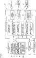
- Fig. 3 is a schematic diagram showing an example of the configuration of the measuring head 14 of the ophthalmologic apparatus 10.
- the measuring head 14 includes the fundus camera unit 14a, the OCT unit 14b, and the stereo camera 20, and is connected to the arithmetic control unit 22.
- the fundus camera unit 14a corresponds to the camera main body of the present invention, and has an optical system which is substantially similar to that of a conventional fundus camera.
- the fundus camera unit 14a irradiates the fundus Ef of the subject eye E with imaging illumination light (flash light or the like) through the objective lens 43, takes an image of the fundus Ef irradiated with the imaging illumination light, and outputs a fundus image D1. Further, the fundus camera unit 14a takes an image of an anterior ocular segment Ea of the subject eye E through the objective lens 43, and outputs an anterior ocular segment image D2 which is an observation image of the anterior ocular segment Ea.
- the OCT unit 14b acquires an OCT image of the fundus Ef through the objective lens 43 and a part of the optical system of the fundus camera unit 14a.
- the arithmetic control unit 22 is, for example, an arithmetic processing device such as a computer that is accommodated in the base 11 or the measuring head 14 and executes various arithmetic processing, control processing, etc.
- the fundus camera unit 14a includes an illumination optical system 30 and an imaging optical system 50, as an optical system for acquiring a fundus image D1 and an anterior ocular segment image D2.
- the illumination optical system 30 irradiates the fundus Ef with illumination light (observation illumination light and imaging illumination light).
- the imaging optical system 50 directs fundus reflection light which is the illumination light reflected from the fundus Ef to, for example, CMOS (Complementary Metal Oxide Semiconductor) type or CCD (Charge Coupled Device) type imaging elements 57, 60 to take an image. Further, the imaging optical system 50 directs signal light output from an OCT optical system 80 (OCT unit 14b) to the fundus Ef, and also directs the signal light passing through the fundus Ef to the OCT optical system 80.
- OCT optical system 80 OCT unit 14b
- the illumination optical system 30 includes an observation light source 31, a reflection mirror 32, a condenser lens 33, a visible light cut filter 34, an imaging light source 35, a mirror 36, relay lenses 37, 38, a diaphragm 39, a small pupil diaphragm (small pupil diaphragm) 39A, a diaphragm switching mechanism 39B, a relay lens 40, a perforated mirror 41, a dichroic mirror 42, the objective lens 43, and the like.
- the imaging optical system 50 includes a focusing lens 51, a mirror 52, a half mirror 53, a visual target display unit 54, a dichroic mirror 55, a condenser lens 56, an imaging element 57, a mirror 58, a condenser lens 59, an imaging element 60, and the like.
- a halogen lamp, an LED (light emitting diode) or the like is used as the observation light source 31.
- the observation light source 31 emits observation illumination light.
- the observation illumination light emitted from the observation light source 31 is reflected by the reflection mirror 32 and passes through the visible light cut filter 34 via the condenser lens 33, to become near-infrared light.
- the observation illumination light having passed through the visible light cut filter 34 is once focused in the vicinity of the imaging light source 35, is reflected by the mirror 36, and passes through the relay lenses 37, 38, the diaphragm 39 (or the small pupil diaphragm 39A) and the relay lens 40.
- the observation illumination light is reflected by a peripheral part of the perforated mirror 41 (a region around the perforated part), then passes through the dichroic mirror 42, and further refracted by the objective lens 43 to illuminate the fundus Ef.
- the fundus reflection light of the observation illumination light is refracted by the objective lens 43, passes through the dichroic mirror 42, the perforated part formed in the central region of the perforated mirror 41, and the focusing lens 51, and then is reflected by the mirror 52. Further, the fundus reflection light passes through the half mirror 53 and then is reflected by the dichroic mirror 55 so that an image of the fundus reflection light is formed on a light receiving surface of the imaging element 57 by the condenser lens 56.
- the imaging element 57 captures (receives) the fundus reflection light and outputs an observation image of the fundus Ef to the arithmetic control unit 22 described later.
- the arithmetic control unit 22 causes the monitor 18 to display the observation image of the fundus Ef.
- the imaging element 57 captures an image of anterior ocular segment reflection light (cornea reflection light), and outputs an anterior ocular segment image D2 to the arithmetic control unit 22.
- the arithmetic control unit 22 causes the monitor 18 to display the anterior ocular segment image D2.
- a xenon lamp, an LED light source or the like is used as the imaging light source 35.
- the imaging light source 35 emits imaging illumination light (flash light) containing at least light in the visible wavelength band.
- the imaging illumination light emitted from the imaging light source 35 travels a path similar to the path for the observation illumination light described above, and irradiates the fundus Ef.
- the fundus reflection light of the imaging illumination light travels a path similar to the path for the fundus reflection light of the observation illumination light, is directed to the dichroic mirror 55, passes through the dichroic mirror 55, and then is reflected by the mirror 58, so that an image of the fundus reflection light is formed on a light receiving surface of the imaging element 60 by the condenser lens 59.
- the imaging element 60 captures (receives) an image of the fundus reflection light, and outputs a fundus image D1 to the arithmetic control unit 22.
- the arithmetic control unit 22 causes the monitor 18 to display the fundus image D1 based on the imaging signal output from the imaging element 60. Note that the monitor 18 for displaying various observation images and the monitor 18 for displaying the fundus image D1 may be the same monitor or separate monitors.
- the small pupil diaphragm 39A is adaptable to a small pupil eye whose pupil diameter d (see Fig. 5 ) is smaller than a standard pupil diameter (for example, 3 to 4 mm) to be a small pupil diameter (for example, less than 2 mm).
- the small pupil diaphragm 39A is held on the optical path of each illumination light by the diaphragm switching mechanism 39B so as to be freely insertable into and extractable from the optical path.
- the small pupil diaphragm 39A is formed to have an aperture diameter smaller than that of the standard diaphragm 39.
- the definitions of the small pupil diameter and the small pupil eye, and the specific shape and function of the small pupil diaphragm 39A are known in publicly known techniques, description on these matters is omitted here (see Japanese Patent Application Laid-Open No. H5-199997 , and Japanese Patent Application Laid-Open No. 2013-165819 ).
- the small pupil diaphragm 39A By inserting the small pupil diaphragm 39A onto the optical path of each illumination light, the fundus Ef can be illuminated with each illumination light even in a case where the subject eye E is a small pupil eye.
- the diaphragm switching mechanism 39B is a publicly known actuator such as a motor drive mechanism that selectively inserts (arranges) the diaphragm 39 and the small pupil diaphragm 39A onto the optical path of the illumination light under the control of the arithmetic control unit 22.
- the arithmetic control unit 22 is adapted to drive the diaphragm switching mechanism 39B according to the switching operation input to the operating unit 16 so that the diaphragm 39 and the small pupil diaphragm 39A can be selectively arranged on the optical path of the illumination light.
- the small pupil diaphragm 39A and the diaphragm switching mechanism 39B may be omitted in the first embodiment.
- the visual target display unit 54 is used for internal vision fixation for projecting vision fixation light of a vision fixation target (bright spot image) onto the subject eye E through the objective lens 43.
- a vision fixation target (bright spot image)
- a dot matrix liquid crystal display LCD: Liquid Crystal Display
- a matrix light emitting diode LED
- the visual target display unit 54 displays the vision fixation target.
- the visual target display unit 54 can arbitrarily set a display mode (shape, etc.) and a display position of the vision fixation target.
- the part of the vision fixation light of the vision fixation target displayed on the visual target display unit 54 After a part of the vision fixation light of the vision fixation target displayed on the visual target display unit 54 is reflected by the half mirror 53, the part of the vision fixation light passes through the mirror 52, the focusing lens 51, the dichroic mirror 55, the perforated part of the perforated mirror 41, the dichroic mirror 42 and the objective lens 43, and then is projected onto the subject eye E.
- the vision fixation target, a visual target for visual acuity measurement, and the like are presented to the subject eye E through the objective lens 43.
- the fundus camera unit 14a includes a focus optical system 70.
- the focus optical system 70 generates a split index for focusing on the fundus Ef.
- the focus optical system 70 includes an LED 71, a relay lens 72, a split index plate 73, a two-hole diaphragm 74, a mirror 75, and a condenser lens 76, and a reflective rod 77.
- the reflective surface of the reflective rod 77 is set on the optical path of the illumination optical system 30 in a case where focus adjustment is performed by the focus optical system 70.
- the focus light emitted from the LED 71 passes through the relay lens 72 and is split into two light beams by the split index plate 73. Then, the focus light passes through the two-hole diaphragm 74, the mirror 75 and the condenser lens 76, and temporarily forms an image on the reflective surface of the reflective rod 77, and then is reflected on the reflective surface to the relay lens 40. Further, the focus light passes through the relay lens 40, the perforated mirror 41, the dichroic mirror 42 and the objective lens 43, and then is projected onto the subject eye E.
- the fundus reflection light of the focus light travels via the objective lens 43, the dichroic mirror 42 and the perforated part of the perforated mirror 41. After that, a part of the fundus reflection light passes through the dichroic mirror 55, travels via the focusing lens 51, the mirror 52, the half mirror 53, the dichroic mirror 55 and the condenser lens 56, and is imaged (image-captured) by the imaging element 57.
- the imaging element 57 captures an image of the fundus reflection light of the focus light, and outputs an imaging signal.
- the split index is displayed on the monitor 18 together with the observation image of the fundus Ef.
- the arithmetic control unit 22 analyzes the position of the split index and moves the focusing lens 51, etc. to automatically perform focusing as in the case of the prior art. Further, an operator may manually perform focusing based on the split index displayed on the monitor 18.
- the dichroic mirror 42 branches the optical path of the OCT optical system 80 from the optical path for fundus imaging.
- the dichroic mirror 42 reflects light in a wavelength band used for OCT measurement, and transmits therethrough light for fundus imaging.
- a collimator lens unit 81, an optical path length changing unit 82, a Galvano scanner 83, a focusing lens 84, a mirror 85, and a relay lens 86 are provided in this order from the OCT unit 14b side, on the optical path of the OCT optical system 80.
- the optical path length changing unit 82 includes, for example, a corner cube and a mechanism for moving the corner cube.
- the optical path length changing unit 82 is movable in a direction of an arrow shown in Fig. 3 , and changes the optical path length of the OCT optical system 80.
- the change of the optical path length is used for correction of the optical path length according to the eye axial length of the subject eye E, adjustment of an interference state, and the like.
- the Galvano scanner 83 changes the traveling direction of signal light passing through the optical path of the OCT optical system 80 so that the fundus Ef can be scanned with the signal light.
- the Galvano scanner 83 includes, for example, a Galvano mirror for scanning signal light in the X direction, a Galvano mirror for scanning signal light in the Y direction, and a mechanism for driving these Galvano mirrors independently of each other. As a result, the signal light can be scanned in any direction on an XY plane.
- the OCT unit 14b includes an interference optical system to be used for acquiring an OCT image of the fundus Ef.
- the OCT unit 14b divides low coherence light into reference light and signal light, causes the signal light traveling via the fundus Ef and the reference light traveling via the reference optical path to interfere with each other so as to generate interference light, and detects spectral components of the interference light.
- a detection result (detection signal) by the OCT unit 14b is output to the arithmetic control unit 22. Since the specific configuration of the OCT unit 14b is a publicly known technique (see, for example, Japanese Patent Application Laid-Open No. 2019-171221 ), specific description thereof is omitted here.
- the first camera 20a and the second camera 20b constituting the stereo camera 20, and simultaneously (including substantially simultaneously) and sequentially take images (video images) of the anterior ocular segment Ea from different sides, that is, from the right and left sides in the present embodiment, and then output the anterior ocular segment image D2 to the arithmetic control unit 22.
- Reference character OB in Fig. 3 designates imaging optical axes of the first camera 20a and the second camera 20b.
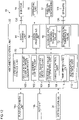
- Fig. 4 is a functional block diagram of the arithmetic control unit 22 of the ophthalmologic apparatus 10 according to the first embodiment.
- the arithmetic control unit 22 includes an integrated control unit 90, a storage unit 92, an image forming unit 94, a data processing unit 96, and the like.
- the fundus camera unit 14a, the OCT unit 14b, the operating unit 16, the electric drive mechanism 17, the monitor 18, the stereo camera 20, and the like described above are connected to the arithmetic control unit 22.
- the storage unit 92 stores image data of the fundus image D1, image data of the OCT image and the like in addition to control programs to be executed by the integrated control unit 90. Further, the storage unit 92 stores an imaging threshold value T1 determined by a threshold value determining unit 106 described later. Note that the storage unit 92 is not necessarily built in the ophthalmologic apparatus 10, but may be built in an external server (database).
- the image forming unit 94 is used together with the OCT unit 14b to acquire an OCT image of the fundus Ef of the subject eye E, and analyzes a detection signal input from the OCT unit 14b to form an OCT image of the fundus Ef.
- a specific method for forming the OCT image is similar to that of a conventional OCT apparatus, and thus description thereof is omitted here.
- the data processing unit 96 performs image processing, etc. on the OCT image formed by the image forming unit 94 and the fundus image D1, etc. acquired by the fundus camera unit 14a.
- the integrated control unit 90 performs integrated control on the operations of the respective components of the ophthalmologic apparatus 10. Further, before the fundus is imaged by the fundus camera unit 14a, the integrated control unit 90 determines based on the anterior ocular segment image D2 whether miosis is caused in the pupil Ep (see Fig. 5 ) of the subject eye E. Then, in a case where it is determined that miosis has been caused in the pupil Ep, the integrated control unit 90 suspends execution of the fundus imaging on the subject eye E until the miosis is settled (released). In a case where it is determined that the miosis in the pupil Ep has been settled, the integrated control unit 90 performs imaging control of executing the fundus imaging on the subject eye E.
- the fundus imaging is performed on the subject eye E which is not a small pupil eye, but a normal eye having a standard pupil diameter described above. Therefore, the imaging control is performed during a second or subsequent fundus imaging operation in the sequential imaging mode or the right-and-left eye imaging mode.
- the function of the integrated control unit 90 may be implemented by using various processors.
- the various processors include CPU (Central Processing Unit), GPU (Graphics Processing Unit), ASIC (Application Specific Integrated Circuit), and programmable logic device [for example, SPLD (Simple Programmable Logic Devices), CPLD (Complex Programmable Logic Device), FPGA (Field Programmable Gate Arrays)] and the like.
- the various functions of the integrated control unit 90 may be implemented by one processor, or may be implemented by a plurality of processors of the same type or different types.
- the integrated control unit 90 functions as an anterior ocular segment image acquiring unit 100, an alignment control unit 102, a pupil diameter detecting unit 104, a threshold value determining unit 106, and an imaging control unit 108 during the fundus imaging on the subject eye E (in the sequential imaging mode, the right-and-left eye imaging mode).
- a unit of the arithmetic control unit 22 may be "-circuit", "-device", or "-equipment”.
- what is referred to as "-unit” may be formed from any of firmware, software, hardware, and a combination thereof.
- Only the functions related to the fundus imaging on the subject eye E in the integrated control unit 90 are shown in Fig. 4 , and specific illustrations for the other functions are omitted because they are known in publicly known techniques.
- the anterior ocular segment image acquiring unit 100 is connected in a wired manner or wirelessly to at least one of the fundus camera unit 14a (imaging element 57) and the stereo camera 20 via a communication interface (not shown), and acquires the anterior ocular segment image D2 from at least one of the fundus camera unit 14a and the stereo camera 20.
- the anterior ocular segment image D2 is used for auto-alignment of the measuring head 14 with the subject eye E.
- the anterior ocular segment image D2 is also used to check the size of the pupil Ep (see Fig. 5 ) before the fundus imaging is performed on the subject eye E by the fundus camera unit 14a. Note that the present embodiment will be described on the assumption that the auto-alignment and the check of the size of the pupil Ep of the subject eye E before the fundus imaging are performed based on the anterior ocular segment image D2 captured by the stereo camera 20.
- the anterior ocular segment image acquiring unit 100 repeatedly acquires the anterior ocular segment image D2 from the stereo camera 20 until the fundus imaging on the subject eye E is completed.
- the alignment control unit 102 calculates the relative position (three-dimensional position) of the subject eye E to the measuring head 14 based on the anterior ocular segment image D2 acquired from the stereo camera 20 by the anterior ocular segment image acquiring unit 100 according to the measurement start operation (see Japanese Patent Application Laid-Open No. 2013-248376 described above). Next, the alignment control unit 102 drives the electric drive mechanism 17 based on a calculation result of the relative position of the subject eye E, and executes the auto-alignment of the measuring head 14 with respect to the subject eye E.
- the pupil diameter detecting unit 104 operates at least before the first fundus imaging operation on the subject eye E by the fundus camera unit 14a, and before the second and subsequent fundus imaging operations.
- first fundus imaging operation means “within a period of time until the first fundus imaging operation on the subject eye E is started” regardless of the type of the imaging mode.
- second and subsequent fundus imaging operations in the sequential imaging mode means “a period of time from after the completion of the N-th fundus imaging operation until before the start of the (N+1)-th fundus imaging operation, when an arbitrary natural number is set to "N”.
- first the second and subsequent fundus imaging operations in the right-and-left eye imaging mode means “a period of time from after the completion of the fundus imaging on one of the right and left eyes until before the start of the fundus imaging on the other eye.
- Fig. 5 is an explanatory diagram showing the detection of the pupil diameter d by the pupil diameter detecting unit 104.
- the pupil diameter detecting unit 104 detects the pupil diameter d, which is the diameter of the pupil Ep of the subject eye E, based on the anterior ocular segment image D2 acquired from at least one of the first camera 20a and the second camera 20b of the stereo camera 20.
- the pupil diameter detecting unit 104 detects a pupillary margin Eb from the anterior ocular segment image D2 acquired from at least one of the first camera 20a and the second camera 20b.
- the pupillary margin Eb can be detected based on the difference in brightness between the pupil Ep and the iris Er in the anterior ocular segment image D2.
- the pupil diameter detecting unit 104 detects (calculates) the pupil diameter d by performing an elliptical approximation on the pupillary margin Eb and calculating the center coordinate of the pupillary margin Eb, based on the detection result of the pupillary margin Eb from the anterior ocular segment image D2. Since a method of detecting the pupil diameter d from the anterior ocular segment image D2 captured by the stereo camera 20 is a publicly known technique, specific description thereof will be omitted here (see, for example, Japanese Patent Application Laid-Open No. 2019-62982 ).
- the pupil diameter detecting unit 104 executes the detection of the pupil diameter d at least once before the first fundus imaging operation on the subject eye E, and repeatedly executes the detection of the pupil diameter d at a plurality of times before the second and subsequent fundus imaging operations. As a result, at least before the second and subsequent fundus imaging operations on the subject eye E, the change in the pupil diameter d of the subject eye E can be detected in real time.
- the threshold value determining unit 106 determines an imaging threshold value T1 (corresponding to a first threshold value of the present invention).
- the imaging threshold value T1 is a lower limit value of the pupil diameter d with which an excellent fundus image D1 can be acquired.
- the imaging threshold value T1 is a threshold value for determining whether the second and subsequent fundus imaging operations on the subject eye T should be executed.
- the subject eye E in the present embodiment is a normal eye, no miosis has been caused in the pupil Ep of the subject eye E before the first fundus imaging operation, that is, in a state where the subject eye E has not been irradiated with imaging illumination light (flash light) even once, and the pupil diameter d is also large enough to obtain an excellent fundus image D1. Therefore, the pupil diameter d of the subject eye E before the first fundus imaging operation can be used as a determination criterion (imaging threshold value T1) for determining whether miosis has been caused in the pupil Ep.
- imaging threshold value T1 determination criterion
- the threshold value determining unit 106 determines the pupil diameter d detected by the pupil diameter detecting unit 104 before the first fundus imaging operation of the subject eye E, as the imaging threshold value T1 as it is. In a case where the pupil diameter detecting unit 104 detects pupil diameters d at a plurality of times, the threshold value determining unit 106 may determine a minimum value, an average value or the like of these detected pupil diameters d, as the imaging threshold value T1.
- the threshold value determining unit 106 may determine, as the imaging threshold value T1, a value which is smaller by only a certain percentage than the pupil diameter d detected by the pupil diameter detecting unit 104 before the first fundus imaging operation on the subject eye E.
- the threshold value determining unit 106 determines the imaging threshold value T1 based on the pupil diameter d detected by the pupil diameter detecting unit 104 as described above. Therefore, even in a case where there are individual differences in the pupil diameter d for respective subjects, it is possible to individually determine imaging threshold values T1 corresponding to the respective subjects.
- the imaging control unit 108 controls the fundus camera unit 14a and the OCT unit 14b to control the imaging of the fundus image D1 and the OCT image of the fundus Ef of the subject eye E.
- the imaging control unit 108 acquires the fundus image D1 by driving the fundus camera unit 14a to perform fundus imaging on the subject eye E after the auto alignment is completed.
- the control of the imaging of the fundus camera unit 14a by the imaging control unit 108 in the case where the imaging mode is the sequential imaging mode or the right-and-left eye imaging mode will be described later.
- the imaging control unit 108 drives the OCT optical system 80, the OCT unit 14b, the image forming unit 94 and the like to acquire an OCT image of the fundus Ef after auto-alignment is completed.
- Fig. 6 is an explanatory diagram showing the imaging control of the fundus camera unit 14a in the sequential imaging mode by the imaging control unit 108.
- the imaging control unit 108 performs a first fundus imaging operation (first imaging of the present invention) on the subject eye E by the fundus camera unit 14a after the auto-alignment is completed. Since the subject eye E is a normal eye as described above, no miosis has been caused in the pupil Ep at the time of the first fundus imaging operation, and the fundus imaging can be performed in the same manner as in the case of the normal mode.
- miosis is caused in the pupil Ep due to irradiation of imaging illumination light (flash light).
- the imaging control unit 108 prior to the second fundus imaging operation on the subject eye E, refers to the imaging threshold value T1 in the storage unit 92 based on the detection result of the pupil diameter d repeatedly detected by the pupil diameter detecting unit 104 and determines whether the pupil diameter d of the subject eye E reaches the imaging threshold value T1 or more. In a case where the pupil diameter d is less than the imaging threshold value T1, the imaging control unit 108 suspends execution of the second fundus imaging operation. In this case, the imaging control unit 108 waits until the pupil diameter d repeatedly detected by the pupil diameter detecting unit 104 reaches the imaging threshold value T1 or more.
- the imaging control unit 108 executes the second fundus imaging operation (second imaging of the present invention) on the subject eye E by the fundus camera unit 14a.
- the second fundus imaging operation on the subject eye E by the fundus camera unit 14a can be automatically executed in accordance with settlement of the miosis of the pupil Ep of the subject eye E.
- the imaging control unit 108 likewise waits until the pupil diameter d of the subject eye E repeatedly detected by the pupil diameter detecting unit 104 reaches the imaging threshold value T1 or more, and when the pupil diameter d reaches the imaging threshold value T1 or more, the imaging control unit 108 executes the fundus imaging on the subject eye E by the fundus camera unit 14a.
- Fig. 7 is an explanatory diagram showing the imaging control of the fundus camera unit 14a in the right-and-left eye imaging mode by the imaging control unit 108.
- the imaging control unit 108 performs the first fundus imaging operation on the subject eye E by the fundus camera unit 14a, that is, the fundus imaging operation on one (for example, the right eye) of the right and left eyes (corresponding to the first imaging of the present invention) after auto-alignment is completed. Since the subject eye E is a normal eye as described above, it is possible to perform the fundus imaging in the same manner as in the case of the first fundus imaging operation in the sequential imaging mode.
- miosis is caused in the pupil Ep of one of the right and left eyes due to irradiation of the imaging illumination light (flash light), and in conjunction with this miosis, miosis is also caused in the pupil Ep of the other eye (for example, the left eye) of the right and left eyes. Further, after the fundus imaging on one of the right and left eyes is completed, the auto-alignment of the measuring head 14 with the other eye of the right and left eyes is performed by the alignment control unit 102.
- the imaging control unit 108 determines whether the pupil diameter d of the other eye of the right and left eyes reaches the imaging threshold value T1 or more as in the case of the second and subsequent fundus imaging operations in the sequential imaging mode. When the pupil diameter d of the other eye of the right and left eyes is less than the imaging threshold value T1, the imaging control unit 108 suspends execution of the fundus imaging on the other eye until the pupil diameter d reaches the imaging threshold value T1 or more.
- the imaging control unit 108 performs the second fundus imaging operation on the subject eye E by the fundus camera unit 14a, that is, the fundus imaging on the other eye of the right and left eyes (corresponding to the second imaging of the present invention).
- the fundus imaging on the other eye by the fundus camera unit 14a can be automatically performed in accordance with settlement of the miosis of the other eye of the right and left eyes.
- Fig. 8 corresponds to a control method of the fundus camera according to the present invention, and is a flowchart showing the flow of fundus imaging processing for the subject eye E by the ophthalmologic apparatus 10 according to the first embodiment.
- description will be made by exemplifying a case where the sequential imaging mode or the right-and-left eye imaging mode is selected as the imaging mode of the fundus imaging.
- the integrated control unit 90 functions as the anterior ocular segment image acquiring unit 100, the alignment control unit 102, the pupil diameter detecting unit 104, the threshold value determining unit 106, and the imaging control unit 108.
- the anterior ocular segment image acquiring unit 100 starts sequential imaging on the anterior ocular segment Ea of the subject eye E by the stereo camera 20.
- the anterior ocular segment image acquiring unit 100 repeatedly acquires the anterior ocular segment image D2 from the stereo camera 20 (step S2).
- the alignment control unit 102 After the alignment control unit 102 detects the relative position of the subject eye E to the measuring head 14 based on the anterior ocular segment image D2 acquired from the stereo camera 20 by the anterior ocular segment image acquiring unit 100, the alignment control unit 102 drives the electric drive mechanism 17 to perform the auto-alignment of the measuring head 14 with the subject eye E (step S3).
- the pupil diameter detecting unit 104 detects of the pupil diameter d of the subject eye E at least once or more (step S5, corresponding to a pupil diameter detecting step of the present invention). Then, the threshold value determining unit 106 determines the imaging threshold value T1 based on the detection result of the pupil diameter d by the pupil diameter detecting unit 104, and stores the imaging threshold value T1 into the storage unit 92 (step S6).
- the timings of the steps S4 and S5 are not particularly limited as long as the steps S4 and S5 are performed before the first fundus imaging operation on the subject eye E by the fundus camera unit 14a, and the steps S4 and S5 may be executed before auto-alignment or during auto-alignment.
- the imaging control unit 108 causes the fundus camera unit 14a to perform the first fundus imaging operation on the subject eye E (step S7).
- the fundus camera unit 14a performs irradiation of the fundus Ef of the subject eye E with imaging illumination light (flash light) and imaging on the fundus Ef, and outputs a fundus image D1 to the arithmetic control unit 22.
- the subject eye E is a normal eye, and thus no miosis has been caused before the first fundus imaging operation. Therefore, an excellent fundus image D1 is obtained.
- the imaging mode of the fundus imaging is the sequential imaging mode
- the acquisition of an anterior ocular segment image D2 from the stereo camera 20 by the anterior ocular segment image acquiring unit 100 step S8, corresponding to an anterior ocular segment image acquiring step of the present invention
- the detection of the pupil diameter d by the pupil diameter detecting unit 104 step S9, corresponding to a pupil diameter detecting step of the present invention
- the alignment control unit 102 performs the auto-alignment of the measuring head 14 with the other eye of the right and left eyes.
- the imaging control unit 108 is held in a standby state until the pupil diameter d repeatedly detected by the pupil diameter detecting unit 104 reaches the imaging threshold value T1 or more, and repetitive control is performed so that the processing of the steps S8 and S9 is repeatedly executed. (NO in step S10).
- the imaging control unit 108 causes the fundus camera unit 14a to perform the second fundus imaging operation on the subject eye E (the other eye of the right and left eyes) when the pupil diameter d repeatedly detected by the pupil diameter detecting unit 104 reaches the imaging threshold value T1 or more (YES in step S10, step S11).
- the fundus camera unit 14a performs the irradiation of the fundus Ef of the subject eye E with the imaging illumination light (flash light) and the imaging on the fundus Ef, and outputs a fundus image D1 to the arithmetic control unit 22.
- step S11 corresponds to an imaging control step of the present invention.
- step S8 to step S11 are repeatedly executed (step S12).
- the second and subsequent fundus imaging operations in which miosis has been caused in the subject eye E it is possible to suspend execution of fundus imaging until the pupil diameter d of the subject eye E reaches the imaging threshold value T1 or more based on the detection result of the pupil diameter detecting unit 104 and perform fundus imaging when the pupil diameter d reaches the imaging threshold value T1 or more.
- T1 the imaging threshold value
- an ophthalmologic apparatus 10 when miosis is caused in the pupil Ep of the subject eye E due to irradiation of the imaging illumination light, execution of the fundus imaging is suspended until the pupil diameter d of the subject eye E reaches the imaging threshold value T1 or more. However, depending on the subject eye E (subject), it may take some time until the miosis of the pupil Ep is settled.
- the fundus imaging on the subject eye E is performed by using the small pupil diaphragm 39A.
- the ophthalmologic apparatus 10 according to the second embodiment has basically the same configuration as the ophthalmologic apparatus 10 according to the first embodiment, except that the function of the imaging control unit 108 is partially different from that in the first embodiment.
- Components having the same functions or configurations as those of the first embodiment are designated by the same reference numerals or reference characters, and the description thereof will be omitted.
- Fig. 9 is a flowchart showing the flow of fundus imaging processing for the subject eye E by the ophthalmologic apparatus 10 according to the second embodiment.
- the processing from step S1 to step S9 is the same as that of the first embodiment described with reference to Fig. 8 , and thus specific description thereof will be omitted.
- the imaging control unit 108 suspends execution of the second fundus imaging operation on the subject eye E when the pupil diameter d repeatedly detected by the pupil diameter detecting unit 104 is less than the imaging threshold value T1 after the first fundus imaging operation on the subject eye E (NO in step S10). Then, the imaging control unit 108 starts to measure a standby time. When the pupil diameter d of the subject eye E reaches the imaging threshold value T1 or more based on the detection result of the pupil diameter detecting unit 104 within a certain predetermined time, the imaging control unit 108 executes the processing of the steps S11 and S12 in the same manner as in the case of the first embodiment (see Fig. 8 ) (NO in step S10A).
- the imaging control unit 108 drives the diaphragm switching mechanism 39B to insert the small pupil diaphragm 39A onto the optical path of the illumination light (YES in step S10A, step S10B).
- the fundus Ef can be illuminated with each illumination light (imaging illumination light, etc.) by using the small pupil diaphragm 39A adaptable to small pupil eyes.
- the imaging control unit 108 causes the fundus camera unit 14a to perform the second fundus imaging operation on the subject eye E (step S11).
- the imaging control unit 108 functions as a first special imaging control unit of the present invention. Since the small pupil diaphragm 39A makes it possible for the fundus camera unit 14a to image the fundus Ef being irradiated with the imaging illumination light, an excellent fundus image D1 can be obtained.
- the imaging control unit 108 drives the diaphragm switching mechanism 39B to retract the small pupil diaphragm 39A from the optical path of the illumination light, and inserts the diaphragm 39 into this optical path.
- step S12 when the third and subsequent fundus imaging operations (in the sequential imaging mode) on the subject eye E are performed, the above-mentioned series of processing is repeatedly executed (step S12).
- the fundus image D1 can be captured in a short time by performing the fundus imaging on the subject eye E in a state where the small pupil diaphragm 39A is inserted on the optical path of the illumination light.
- the small pupil diaphragm 39A in a case where it takes time until the miosis of the pupil Ep of the subject eye E has been settled, the small pupil diaphragm 39A is inserted (arranged) on the optical path of the illumination light.
- the small pupil diaphragm 39A in the second embodiment is not particularly limited as long as the diaphragm diameter thereof is smaller than at least that of the diaphragm 39, and a diaphragm having a diaphragm diameter larger than that of a general small pupil diaphragm 39A may be used.
- variable diaphragm including a liquid crystal shutter
- diaphragm diameter can be adjusted according to the amount of miosis of the pupil Ep of the subject eye E, as the small pupil diaphragm 39A according to the second embodiment.
- Fig. 10 is a functional block diagram of an arithmetic control unit 22 of an ophthalmologic apparatus 10 according to a third embodiment.
- the ophthalmologic apparatus 10 of each of the above-mentioned embodiments performs the fundus imaging on a normal eye as a subject eye E, but the ophthalmologic apparatus 10 according to the third embodiment performs the fundus imaging on a small pupil eye as a subject eye E.
- the fundus imaging is performed on the subject eye E in a state where the small pupil diaphragm 39A is automatically inserted on the optical path of illumination light.
- the ophthalmologic apparatus 10 has basically the same configuration as the ophthalmologic apparatus 10 of each of the above-mentioned embodiments except that the integrated control unit 90 functions as a small pupil diameter determining unit 109, the functions of the imaging control unit 108 are partially different, and a determination threshold value T2 is stored in the storage unit 92. Therefore, components having the same functions or configurations as those of each of the above-mentioned embodiments are designated by the same reference numerals or reference characters, and the description thereof will be omitted.
- the small pupil diameter determining unit 109 determines whether the subject eye E is a small pupil eye before the first fundus imaging operation on the subject eye E.
- the determination threshold value T2 (corresponding to a second threshold value of the present invention) is a threshold value to be used for determination by the small pupil diameter determining unit 109, and the determination threshold value T2 is set to a value smaller than the imaging threshold value T1, for example, 2 mm (see Japanese Patent Application Laid-Open No. 2013-165819 ). Note that the determination threshold value T2 may be individually prepared for each of various conditions related to the pupil diameter d of the small pupil eye such as the age of a subject.
- the imaging control unit 108 functions as a second special imaging control unit of the present invention in a case where the subject eye E is a small pupil eye, and performs the fundus imaging on the subject eye E by using the small pupil diaphragm 39A.
- Fig. 11 is a flowchart showing the flow of fundus imaging processing on the subject eye E by the ophthalmologic apparatus 10 according to the third embodiment. Since the processing from step S1 to step S5 are the same as that of the first embodiment described with reference to Fig. 8 described above, specific description thereof will be omitted.
- the small pupil diameter determining unit 109 refers to the determination threshold value T2 in the storage unit 92 based on the pupil diameter d detected by the pupil diameter detecting unit 104 to determine whether the subject eye E is a small pupil eye (step S5A). Specifically, the small pupil diameter determining unit 109 determines whether the subject eye E is a small pupil eye based on whether the pupil diameter d is less than the determination threshold value T2.
- step S5A In a case where the subject eye E is determined to be a normal eye by the small pupil diameter determining unit 109, the same processing as that of each of the above-mentioned embodiments (see Figs. 8 and 9 ) is executed (No in step S5A).
- the imaging control unit 108 drives the diaphragm switching mechanism 39B to insert the small pupil diaphragm 39A onto the optical path of illumination light (YES in step S5A, step S5B). Then, the imaging control unit 108 causes the fundus camera unit 14a to perform the first fundus imaging operation on the subject eye E in a state where the small pupil diaphragm 39A is inserted on the optical path (step S5C). Because the fundus imaging is performed on the subject eye E with the small pupil diaphragm 39A adaptable to the small pupil eye, an excellent fundus image D1 can be obtained even when the subject eye E is a small pupil eye.
- the alignment control unit 102 upon completion of the first fundus imaging operation on the subject eye E, the alignment control unit 102 performs auto-alignment of the measuring head 14 with the other eye of the right and left eyes.
- the imaging control unit 108 causes the fundus camera unit 14a to perform the second fundus imaging operation on the subject eye E in a state where the small pupil diaphragm 39A is inserted on the optical path of illumination light (step S5D).
- the imaging control unit 108 causes the fundus camera unit 14a to perform the second fundus imaging operation on the subject eye E in a state where the small pupil diaphragm 39A is inserted on the optical path of illumination light (step S5D).
- an excellent fundus image D1 can be obtained as in the case of the first fundus imaging operation.
- step S5D when the third and subsequent fundus imaging operations (in the sequential imaging mode) is performed on the subject eye E, the processing of step S5D is repeatedly executed (step S5E).
- the third embodiment it is possible to determine based on the detection result of the pupil diameter detecting unit 104 whether the subject eye E is a small pupil eye, and in a case where it is determined that the subject eye E is a small pupil eye, it is also possible to automatically insert the small pupil diaphragm 39A onto the optical path of the illumination light and then perform the fundus imaging on the subject eye E by the fundus camera unit 14a. As a result, an excellent fundus image D1 can be obtained even in a case where the subject eye E is a small pupil eye. Further, the small pupil diaphragm 39A can be automatically inserted onto the optical path of the illumination light without the operator's switching operation on the operating unit 16.
- Fig. 12 is a functional block diagram of an arithmetic control unit 22 of an ophthalmologic apparatus 10 according to a fourth embodiment.
- the ophthalmologic apparatus 10 according to each of the above-mentioned embodiments suspends the execution of the fundus imaging until the pupil diameter d reaches the imaging threshold value T1 or more in the second and subsequent fundus imaging operations on the subject eye E (excluding the small pupil eye). In this case, it is unknown when the fundus imaging is to be performed.
- the ophthalmologic apparatus 10 predicts a return time t required until the pupil diameter d of the subject eye E in which miosis has been caused due to irradiation of imaging illumination light increases up to the imaging threshold value T1, and notifies the predicted return time t.
- the ophthalmologic apparatus 10 according to the fourth embodiment has basically the same configuration as the ophthalmologic apparatus 10 according to each of the above-mentioned embodiments except that a speaker 119 is connected to the arithmetic control unit 22 and the integrated control unit 90 functions as a time predicting unit 110 and a notification control unit 112. Therefore, components having the same functions or configurations as those of each of the above-mentioned embodiments are designated by the same reference numerals or reference characters, and the description thereof will be omitted. Further, the fourth embodiment will be described on the assumption that the subject eye E is a normal eye.
- Fig. 13 is an explanatory diagram showing a first example of prediction of the return time t by the time predicting unit 110.
- the time predicting unit 110 predicts the return time t based on pupil diameter information 120 indicating a detection result of a new pupil diameter d by the pupil diameter detecting unit 104, light source information 122 indicating a type of the imaging light source 35, and subject information 124 indicating age, disease and the like of the subject.
- the return time t varies according to the amount of miosis of the pupil Ep (pupil diameter d) in the first fundus imaging operation on the subject eye E, and for example, the return time t becomes longer as the amount of miosis is larger. Further, the return time t varies according to the type of the imaging light source 35 (the type of the imaging illumination light), for example, the return time t becomes longer or conversely shorter depending on specific imaging light sources 35. Further, the return time t also varies according to the age, disease and the like of the subject. For example, when the subject is elderly or has a disease such as eye strain, the return time t becomes longer.
- the time predicting unit 110 can predict the return time t based on the pupil diameter information 120, the light source information 122, and the subject information 124.
- the light source information 122 is stored in the storage unit 92 in advance, and the subject information 124 can be input via the operating unit 16 or obtained from a hospital database or the like.
- the time predicting unit 110 predicts the return time t by referring to a data table generated in advance based on the pupil diameter information 120, the light source information 122, and the subject information 124. Further, the time predicting unit 110 may predict the return time t by using a trained model (learned model) into which the pupil diameter information 120, the light source information 122, and the subject information 124 are input and from which the return time t is output. The time predicting unit 110 outputs return time information 126 indicating an prediction result of the return time t to the notification control unit 112.
- the return time t (return time information 126) predicted by the time predicting unit 110 is updated every time the pupil diameter detecting unit 104 detects a new pupil diameter d, that is, every time the pupil diameter information 120 is updated.
- the time predicting unit 110 predicts the return time t based on the pupil diameter information 120, the light source information 122, and the subject information 124.
- the light source information 122 and the subject information 124 are not indispensable, and the return time t may be predicted based on only the pupil diameter information 120.
- the time predicting unit 110 may predict the return time t based on at least the pupil diameter information 120.
- Fig. 14 is an explanatory diagram showing a second example of the prediction of the return time t by the time predicting unit 110.
- a change of the pupil diameter d over time from the time when miosis is caused in the pupil Ep of the subject eye E due to irradiation of imaging illumination light until the time when the miosis of the pupil Ep is settled to restore an original state is generally represented by a waveform W as illustrated in Fig. 14 . Therefore, the time predicting unit 110 can calculate prediction values PV (indicated by a dotted line in Fig. 14 ) of the change of the pupil diameter d over time, by calculating the waveform W based on a change (indicated by a solid line in Fig.
- the time predicting unit 110 can predict the return time t and output the return time information 126 to the notification control unit 112 before the miosis of the pupil Ep of the subject eye E is settled (before the pupil diameter d reaches the imaging threshold value T1).
- Fig. 15 is an explanatory diagram showing an example of displaying the return time information 126 on the monitor 18.
- the notification control unit 112 constitutes a notifying unit of the present invention together with the monitor 18 and the speaker 119.
- the notification control unit 112 outputs the return time information 126 input from the time predicting unit 110 to the monitor 18 and the speaker 119.
- the return time information 126 is displayed on the monitor 18 together with, for example, the anterior ocular segment image D2 (video image). Further, the return time information 126 is output with voice from the speaker 119.
- Fig. 16 is a flowchart showing the flow of the fundus imaging processing on the subject eye E by the ophthalmologic apparatus 10 according to the fourth embodiment. Since the processing from step S1 to step S9 is the same as those of the first embodiment (see Fig. 8 ) and the second embodiment (see Fig. 12 ) described above, specific description thereof will be omitted.
- the time predicting unit 110 when the pupil diameter d repeatedly detected by the pupil diameter detecting unit 104 is less than the imaging threshold value T1 after the first fundus imaging operation on the subject eye E by the fundus camera unit 14a is completed (No in step S10), the time predicting unit 110 operates.
- the time predicting unit 110 predicts the return time t and outputs the return time information 126 to the notification control unit 112 as described with reference to Fig. 13 or Fig. 14 , based on the detection result of the pupil diameter detecting unit 104 and the like (step S10 ⁇ ).
- the notification control unit 112 outputs the return time information 126 input from the time predicting unit 110 to the monitor 18 and the speaker 119 (step S10 ⁇ ). As a result, as shown in Fig. 15 described above, the return time information 126 is notified from the monitor 18 and the speaker 119 (screen display and voice output).
- steps S8 to S10, S10 ⁇ , and S10 ⁇ is repeatedly executed until the pupil diameter d repeatedly detected by the pupil diameter detecting unit 104 reaches the imaging threshold value T1 or more.
- the update of the prediction result of the return time t by the time predicting unit 110 and the notification of the return time information 126 by the notification control unit 112 are repeatedly performed (NO in step S10).
- the processing to be executed after the pupil diameter d reaches the imaging threshold value T1 or more is the same as that of the first embodiment, the description thereof will be omitted.
- the fundus imaging on the subject eye E may be performed by using the small pupil diaphragm 39A in the same manner as in the case of the second embodiment.
- the return time t required until the miosis of the pupil Ep of the subject eye E is settled can be predicted and notified to the operator or the like.
- the operator can recognize the return time t, that is, the timings at which the second and subsequent fundus imaging operations on the subject eye E are started.
- the monitor 18 and the speaker 119 are used to notify the return time information 126 (return time t), but only one of the monitor 18 and the speaker 119 may be used to notify the return time information 126.
- the imaging threshold value T1 is determined based on the pupil diameter d before the first fundus imaging operation on the subject eye E, and the imaging control is executed in the second and subsequent fundus imaging operations based on this imaging threshold value T1.
- the imaging control is executed from the time when the first fundus imaging operation on the subject eye E is performed.
- the ophthalmologic apparatus 10 has basically the same configuration as the ophthalmologic apparatus 10 of each of the above-mentioned embodiments except that the imaging threshold value T1 is stored in the storage unit 92 in advance. Therefore, components having the same functions or configurations as those of each of the above-mentioned embodiments are designated by the same reference numerals or reference characters, and the description thereof will be omitted.
- the imaging threshold value T1 is, for example, a threshold value determined based on a standard pupil diameter d, or a threshold value which is individually determined for each of various conditions such as the age, disease and the like of the subject.
- the pupil diameter d of the pupil Ep of each subject may be measured in advance and stored in a database of a hospital or the like, so that the threshold value determining unit 106 accesses the database to acquire information on the pupil diameter d of the subject, determines an imaging threshold value T1 based on thus-acquired information and stores the imaging threshold value T1 in the storage unit 92.
- Fig. 17 is a flowchart showing the flow of fundus imaging processing on the subject eye E by the ophthalmologic apparatus 10 according to the fifth embodiment. Since the processing from step S1 to step S3 is the same as that of the first embodiment described with reference to Fig. 8 described above, specific description thereof will be omitted.
- the imaging control unit 108 suspends execution of the first fundus imaging operation on the subject eye E until the pupil diameter d reaches the imaging threshold value T1 or more based on the detection result of the pupil diameter d (NO in step S10C).
- the imaging control unit 108 causes the fundus camera unit 14a to execute the first fundus imaging operation on the subject eye E (YES in step S10C, step S11).
- the first fundus imaging operation by the fundus camera unit 14a can be automatically performed at a time of the settlement of the miosis.
- an excellent fundus image D1 can be obtained.
- the fundus imaging on the subject eye E may be performed by using the small pupil diaphragm 39A.
- step S4 the processing from step S4 to step S11C is repeatedly executed (steps S12 and S13).
- the imaging threshold value T1 is determined in advance, so that the imaging control can be executed from the time when the first fundus imaging operation on the subject eye E is performed.
- an excellent fundus image D1 can be obtained even when miosis has been caused in the pupil Ep of the subject eye E due to another examination performed before the fundus imaging.
- the pupil diameter detecting unit 104 detects the pupil diameter d of the subject eye E based on the anterior ocular segment image D2 captured by the stereo camera 20.
- the pupil diameter d may be detected based on the anterior ocular segment image D2 captured by the fundus camera unit 14a. Even in this case, it is also possible to perform the imaging control by the imaging control unit 108 described above.
- the capture of the anterior ocular segment image D2 by the stereo camera 20 or the fundus camera unit 14a is repeatedly performed (sequentially performed) during the period of time from the time when an imaging start operation is performed until the time when all the fundus imaging operations on the subject eye E are completed.
- the capture of the anterior ocular segment image D2 may be repeatedly performed for only a predetermined period of time before the fundus imaging on the subject eye E.
- the diaphragm 39 and the small pupil diaphragm 39A are separately provided.
- a variable diaphragm having an adjustable diaphragm diameter may function as the diaphragm 39 and the small pupil diaphragm 39A.
- the composite machine of the fundus camera and the optical coherence tomography meter has been described as an example, but the present invention is also applicable to a fundus camera (non-mydriatic fundus camera) that performs fundus imaging on a subject eye E under non-mydriasis.
- a fundus camera non-mydriatic fundus camera
Landscapes
- Life Sciences & Earth Sciences (AREA)
- Health & Medical Sciences (AREA)
- Medical Informatics (AREA)
- Biophysics (AREA)
- Ophthalmology & Optometry (AREA)
- Engineering & Computer Science (AREA)
- Biomedical Technology (AREA)
- Heart & Thoracic Surgery (AREA)
- Physics & Mathematics (AREA)
- Molecular Biology (AREA)
- Surgery (AREA)
- Animal Behavior & Ethology (AREA)
- General Health & Medical Sciences (AREA)
- Public Health (AREA)
- Veterinary Medicine (AREA)
- Eye Examination Apparatus (AREA)
Applications Claiming Priority (1)
| Application Number | Priority Date | Filing Date | Title |
|---|---|---|---|
| JP2020159690A JP2022053081A (ja) | 2020-09-24 | 2020-09-24 | 眼底カメラ及びその制御方法 |
Publications (1)
| Publication Number | Publication Date |
|---|---|
| EP3973850A1 true EP3973850A1 (de) | 2022-03-30 |
Family
ID=77465882
Family Applications (1)
| Application Number | Title | Priority Date | Filing Date |
|---|---|---|---|
| EP21192787.6A Pending EP3973850A1 (de) | 2020-09-24 | 2021-08-24 | Funduskamera und steuerverfahren dafür |
Country Status (3)
| Country | Link |
|---|---|
| US (1) | US20220087525A1 (de) |
| EP (1) | EP3973850A1 (de) |
| JP (1) | JP2022053081A (de) |
Families Citing this family (1)
| Publication number | Priority date | Publication date | Assignee | Title |
|---|---|---|---|---|
| US11504001B2 (en) * | 2021-03-31 | 2022-11-22 | Raytrx, Llc | Surgery 3D visualization apparatus |
Citations (13)
| Publication number | Priority date | Publication date | Assignee | Title |
|---|---|---|---|---|
| JPH05199997A (ja) | 1992-01-29 | 1993-08-10 | Canon Inc | 小瞳孔撮影が可能な眼底カメラ |
| US20100057059A1 (en) * | 2006-11-29 | 2010-03-04 | Nidek Co., Ltd. | Corneal surgery apparatus |
| EP2138093B1 (de) * | 2007-11-08 | 2011-05-04 | Nidek Co., Ltd. | Funduskamera |
| US20120224141A1 (en) * | 2011-03-01 | 2012-09-06 | Nidek Co., Ltd. | Fundus photographing apparatus |
| US20130208243A1 (en) * | 2012-02-15 | 2013-08-15 | Canon Kabushiki Kaisha | Ophthalmologic apparatus, method for controlling ophthalmologic apparatus, and storage medium |
| JP2013165819A (ja) | 2012-02-15 | 2013-08-29 | Canon Inc | 眼科装置および眼科制御方法並びにプログラム |
| JP2013248376A (ja) | 2012-05-01 | 2013-12-12 | Topcon Corp | 眼科装置 |
| US20140300864A1 (en) * | 2013-04-03 | 2014-10-09 | Kabushiki Kaisha Topcon | Ophthalmologic apparatus |
| EP2786698B1 (de) * | 2013-04-03 | 2015-11-18 | Kabushiki Kaisha Topcon | Ophthalmologische Vorrichtung |
| US20160120405A1 (en) * | 2014-10-29 | 2016-05-05 | Kabushiki Kaisha Topcon | Ophthalmologic apparatus |
| JP2019062982A (ja) | 2017-09-28 | 2019-04-25 | 株式会社トプコン | 眼科装置及び瞳孔状態計測方法 |
| JP2019171221A (ja) | 2019-07-23 | 2019-10-10 | 株式会社トプコン | 眼科撮影装置及び眼科情報処理装置 |
| WO2020032128A1 (ja) * | 2018-08-08 | 2020-02-13 | 興和株式会社 | 眼科撮影装置 |
Family Cites Families (2)
| Publication number | Priority date | Publication date | Assignee | Title |
|---|---|---|---|---|
| JP6112846B2 (ja) * | 2012-12-11 | 2017-04-12 | 株式会社トプコン | 眼科装置 |
| WO2019030375A2 (en) * | 2017-08-11 | 2019-02-14 | Carl Zeiss Meditec, Inc. | SYSTEMS AND METHODS FOR ENHANCED OPHTHALMOLOGIC IMAGING |
-
2020
- 2020-09-24 JP JP2020159690A patent/JP2022053081A/ja active Pending
-
2021
- 2021-08-04 US US17/393,412 patent/US20220087525A1/en active Pending
- 2021-08-24 EP EP21192787.6A patent/EP3973850A1/de active Pending
Patent Citations (14)
| Publication number | Priority date | Publication date | Assignee | Title |
|---|---|---|---|---|
| JPH05199997A (ja) | 1992-01-29 | 1993-08-10 | Canon Inc | 小瞳孔撮影が可能な眼底カメラ |
| US20100057059A1 (en) * | 2006-11-29 | 2010-03-04 | Nidek Co., Ltd. | Corneal surgery apparatus |
| EP2138093B1 (de) * | 2007-11-08 | 2011-05-04 | Nidek Co., Ltd. | Funduskamera |
| US20120224141A1 (en) * | 2011-03-01 | 2012-09-06 | Nidek Co., Ltd. | Fundus photographing apparatus |
| US20130208243A1 (en) * | 2012-02-15 | 2013-08-15 | Canon Kabushiki Kaisha | Ophthalmologic apparatus, method for controlling ophthalmologic apparatus, and storage medium |
| JP2013165819A (ja) | 2012-02-15 | 2013-08-29 | Canon Inc | 眼科装置および眼科制御方法並びにプログラム |
| JP2013248376A (ja) | 2012-05-01 | 2013-12-12 | Topcon Corp | 眼科装置 |
| US20140300864A1 (en) * | 2013-04-03 | 2014-10-09 | Kabushiki Kaisha Topcon | Ophthalmologic apparatus |
| EP2786698B1 (de) * | 2013-04-03 | 2015-11-18 | Kabushiki Kaisha Topcon | Ophthalmologische Vorrichtung |
| US20160120405A1 (en) * | 2014-10-29 | 2016-05-05 | Kabushiki Kaisha Topcon | Ophthalmologic apparatus |
| JP2019062982A (ja) | 2017-09-28 | 2019-04-25 | 株式会社トプコン | 眼科装置及び瞳孔状態計測方法 |
| WO2020032128A1 (ja) * | 2018-08-08 | 2020-02-13 | 興和株式会社 | 眼科撮影装置 |
| US20210307604A1 (en) * | 2018-08-08 | 2021-10-07 | Kowa Company, Ltd. | Ophthalmic photographing apparatus |
| JP2019171221A (ja) | 2019-07-23 | 2019-10-10 | 株式会社トプコン | 眼科撮影装置及び眼科情報処理装置 |
Non-Patent Citations (1)
| Title |
|---|
| BIRCH E E ET AL: "Pupillometric measures of retinal sensitivity in infants and adults with retinitis pigmentosa", VISION RESEARCH, ELSEVIER, AMSTERDAM, NL, vol. 27, no. 4, 1 January 1987 (1987-01-01), pages 499 - 505, XP024311612, ISSN: 0042-6989, [retrieved on 19870101], DOI: 10.1016/0042-6989(87)90034-4 * |
Also Published As
| Publication number | Publication date |
|---|---|
| JP2022053081A (ja) | 2022-04-05 |
| US20220087525A1 (en) | 2022-03-24 |
Similar Documents
| Publication | Publication Date | Title |
|---|---|---|
| US10039450B2 (en) | Ophthalmologic apparatus | |
| EP2997881B1 (de) | Ophthalmische vorrichtung | |
| JP6641730B2 (ja) | 眼科装置、および眼科装置用プログラム | |
| EP3449811A1 (de) | Ophthalmische vorrichtung und programm zur steuerung einer ophthalmischen vorrichtung | |
| JP2012217665A (ja) | 眼科撮影装置 | |
| EP3973850A1 (de) | Funduskamera und steuerverfahren dafür | |
| EP3888528A1 (de) | Ophthalmische vorrichtung | |
| JP6788445B2 (ja) | 眼科装置 | |
| JP3660145B2 (ja) | 眼科装置 | |
| US20220248947A1 (en) | Ophthalmologic device and method for controlling same | |
| JP6634765B2 (ja) | 眼科装置、および眼科装置制御プログラム | |
| JP6769092B2 (ja) | 眼科装置 | |
| JP6769091B2 (ja) | 眼科装置、および眼科装置制御プログラム | |
| JP7550586B2 (ja) | 眼科装置及びその作動方法 | |
| JP7491218B2 (ja) | 眼科装置、および眼科装置制御プログラム | |
| JP7187769B2 (ja) | 眼科装置、および眼科装置制御プログラム | |
| WO2022209992A1 (ja) | 眼科装置 | |
| JP6930841B2 (ja) | 眼科装置 | |
| JP6930842B2 (ja) | 眼科装置 | |
| JP2017196303A (ja) | 眼科装置、および眼科装置制御プログラム | |
| JP2023010416A (ja) | 眼科測定装置 | |
| JP2022031533A (ja) | 眼科撮影装置 | |
| JP2020179271A (ja) | 眼科装置 | |
| JP2020124350A (ja) | 眼科装置 | |
| JP2020179272A (ja) | 眼科装置 |
Legal Events
| Date | Code | Title | Description |
|---|---|---|---|
| PUAI | Public reference made under article 153(3) epc to a published international application that has entered the european phase |
Free format text: ORIGINAL CODE: 0009012 |
|
| STAA | Information on the status of an ep patent application or granted ep patent |
Free format text: STATUS: THE APPLICATION HAS BEEN PUBLISHED |
|
| AK | Designated contracting states |
Kind code of ref document: A1 Designated state(s): AL AT BE BG CH CY CZ DE DK EE ES FI FR GB GR HR HU IE IS IT LI LT LU LV MC MK MT NL NO PL PT RO RS SE SI SK SM TR |
|
| STAA | Information on the status of an ep patent application or granted ep patent |
Free format text: STATUS: REQUEST FOR EXAMINATION WAS MADE |
|
| 17P | Request for examination filed |
Effective date: 20220929 |
|
| RBV | Designated contracting states (corrected) |
Designated state(s): AL AT BE BG CH CY CZ DE DK EE ES FI FR GB GR HR HU IE IS IT LI LT LU LV MC MK MT NL NO PL PT RO RS SE SI SK SM TR |
|
| STAA | Information on the status of an ep patent application or granted ep patent |
Free format text: STATUS: EXAMINATION IS IN PROGRESS |
|
| 17Q | First examination report despatched |
Effective date: 20240129 |