EP3973822B1 - Vorrichtung zur befestigung und zum verstellen einer kopfstütze - Google Patents
Vorrichtung zur befestigung und zum verstellen einer kopfstütze Download PDFInfo
- Publication number
- EP3973822B1 EP3973822B1 EP21199438.9A EP21199438A EP3973822B1 EP 3973822 B1 EP3973822 B1 EP 3973822B1 EP 21199438 A EP21199438 A EP 21199438A EP 3973822 B1 EP3973822 B1 EP 3973822B1
- Authority
- EP
- European Patent Office
- Prior art keywords
- shaft
- sleeve
- backrest
- headrest
- longitudinal axis
- Prior art date
- Legal status (The legal status is an assumption and is not a legal conclusion. Google has not performed a legal analysis and makes no representation as to the accuracy of the status listed.)
- Active
Links
Images


Classifications
-
- A—HUMAN NECESSITIES
- A47—FURNITURE; DOMESTIC ARTICLES OR APPLIANCES; COFFEE MILLS; SPICE MILLS; SUCTION CLEANERS IN GENERAL
- A47C—CHAIRS; SOFAS; BEDS
- A47C7/00—Parts, details, or accessories of chairs or stools
- A47C7/36—Supports for the head or the back
- A47C7/38—Supports for the head or the back for the head, e.g. detachable
Definitions
- the invention relates to a device for fastening a headrest of a piece of seating furniture or a piece of reclining furniture to a backrest of the piece of seating furniture or the piece of reclining furniture and for adjusting the headrest relative to the backrest.
- Modern seating furniture sometimes has adjustment options to increase seating comfort.
- Seating furniture with adjustment options is, for example, EN 10 2012 100 200 A1 , EN 20 2018 104 018 U1 or EN 20 2016 100 865 U1 known.
- the device according to the invention aims to create an adjustment option for the headrest of a piece of seating furniture or a piece of reclining furniture relative to the backrest of the piece of seating furniture or a piece of reclining furniture.
- the height and inclination of the headrest relative to the backrest are adjustable.
- the device according to the invention comprises a shaft extending along its longitudinal axis, which is intended for arrangement on the headrest.
- the device also comprises a sleeve extending along its longitudinal axis, which is intended for arrangement on the backrest.
- the shaft is mounted in the sleeve as intended, the longitudinal axis of the sleeve and the longitudinal axis of the shaft being parallel to one another or coinciding.
- the shaft is displaceable in the sleeve along its longitudinal axis and along the longitudinal axis of the sleeve.
- a fastening element is provided, which serves to attach the headrest to the shaft.
- the fastening element is rotatably attached to the shaft in order to be able to change the inclination of the headrest.
- the fastening element can be rotated about an axis which extends essentially perpendicular to the longitudinal axis of the shaft.
- the fastening element can be attached to a first end of the shaft or in the region of the first end of the shaft.
- the rotation of the fastening element relative to the shaft can take place independently of the position that the shaft assumes relative to the sleeve.
- the displacement of the shaft in the sleeve can also take place independently of the position that the fastening means assumes relative to the shaft.
- the fastening element can be fastened to the shaft by means of a locking connection.
- the number of lockable positions that the fastening means can assume relative to the shaft can be, for example, six. However, more or fewer positions can also be provided.
- the total angle in which the fastening means can rotate about the said axis, i.e. the total angle enclose the two outer lockable positions can be, for example, 120°.
- the shaft can be provided with a securing element in the region of its second end, which is opposite the first end.
- the securing element can extend transversely to the longitudinal axis of the shaft and protrude beyond the shaft transversely to the longitudinal axis of the shaft.
- the securing element can be detachable from the shaft and, for example, be designed as a securing split pin.
- a receiving opening can be provided in the region of the second end of the shaft to accommodate the securing element.
- the securing element can be retractable in the shaft and, for example, be elastically mounted for this purpose.
- the shaft can, for example, be made of a metal or at least have a metallic surface coating.
- the sleeve has a first radial projection in the region of its first end and a second radial projection in the region of its second end.
- the radial projections serve to axially fix the sleeve to the backrest, in particular to a skeleton or frame of the backrest.
- the skeleton or frame can have a corresponding receptacle in which the sleeve is arranged as intended, while the radial projections extend outside the receptacle.
- the second radial projection can be elastically designed or elastically mounted.
- the second radial projection can thus deform when the second end of the sleeve penetrates the receptacle in order to insert the sleeve into the receptacle or to remove it from the receptacle.
- the sleeve can have one or more slots in the region of its second end that extend along the longitudinal axis of the sleeve, so that resilient legs are formed between the slots, which give the sleeve section elasticity.
- the first end of the sleeve faces the first end of the shaft and that the second end of the sleeve faces the second end of the shaft.
- An insert with a through-opening for the shaft is arranged in or on the sleeve, which forms the counterpart to the shaft.
- the insert can extend over only a section of the sleeve (along its longitudinal axis).
- the insert can be flat and extend transversely to the longitudinal axis of the sleeve.
- the insert can be arranged in the region of the first end of the sleeve, in particular in a receptacle which is formed, for example, in the first radial projection of the sleeve in the region of the first end of the sleeve.
- the insert is pre-tensioned in a direction transverse to the longitudinal axis of the sleeve in order to improve the hold of the shaft (with the insert) in the sleeve (at a certain height of the headrest).
- a spring element for example, can be used to pre-tension the insert.
- the shaft can have a slightly larger diameter than the through-opening of the insert, so that the shaft is firmly mounted in the sleeve by means of the insert.
- the shaft can have a diameter of 10 mm, while the insert has a diameter of 9.9 mm.
- the sleeve can have a larger diameter than the shaft.
- the diameter of the sleeve can be, for example, 15 to 20 mm, in particular 17 mm.
- the sleeve can be covered with a decorative cap in the area of its first end.
- the decorative cap can be made of the same material as the shaft.
- the device can comprise a braking device, which is also intended to be arranged on the backrest.
- the braking device can, as intended, encompass a section of the shaft and brake a movement of the shaft along its longitudinal axis. This can, for example, ensure that the headrest does not slip into a lower position due to its weight alone.
- the static friction between the surface of the braking device facing the shaft on the one hand and the shaft on the other hand can be dimensioned such that its amount exceeds the weight of the headrest. The static friction counteracts the weight, so that the headrest ultimately does not slip down.
- the sliding friction between the surface of the braking device facing the shaft on the one hand and the shaft on the other hand can be dimensioned such that the user feels resistance when adjusting the height of the headrest and can therefore set a certain height quite precisely.
- the braking device can comprise a material on its surface facing the shaft that controls the movement of the shaft through friction.
- the invention also relates to a piece of seating furniture and a piece of reclining furniture with a backrest and a headrest, wherein the headrest is attached to the backrest by means of the device according to the invention and is adjustable relative to the backrest.
- the piece of seating furniture or the reclining furniture can in particular be an upholstered piece of furniture, such as an armchair, a sofa, a couch, a chaise longue or a chaise longue.
- FIG 1 a section of a seat component for a sofa is shown in perspective.
- the seat component comprises a backrest 1 and a headrest 2 attached to the backrest 1.
- the headrest 2 is located in Figure 1 in a first position in which the headrest 2 extends in the plane of the backrest 1 and forms an extension of the backrest 1.
- the headrest 2 assumes a second position in which it is essentially horizontal and bent relative to the backrest 1.
- the headrest 2 can be moved from the first to the second position by a rotary movement.
- Two maximum deflections of the headrest are provided, between which the headrest 2 can be adjusted by means of a rotary movement.
- the angle between the maximum deflections can be 120°, for example.
- the second position ( Figure 2 ) represents a maximum deflection
- the first position ( Figure 1 ) represents an intermediate position between the two maximum deflections.
- the Figures 3 and 4 show the headrest 2 from two perspectives in a third position in which the headrest 2 is spaced apart from the backrest 1 in the vertical direction.
- the headrest 2 can be moved from the first to the third position and vice versa by a linear movement (essentially in the vertical direction).
- the first position Figure 1
- the third position Figures 3 and 4
- the headrest can assume 2 further positions.
- the travel between the uppermost and the lowermost position can be, for example, 20 cm.
- the seat component comprises a device 3 for adjusting the headrest 2 relative to the backrest 1, wherein the device 3 also serves to attach the headrest 2 to the backrest 1.
- the device 3 is attached on the one hand to a frame 11 of the backrest 1 and on the other hand to a frame 21 of the headrest 2.
- the frames 11, 21 form a basic structure of the backrest 1 and the headrest 2 and serve as a holding structure for upholstery elements.
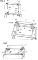
- the Racks 11, 21 are in Figure 5 in the separated state and in the Figures 6 ( 15 ) and 7 in the state connected by the device 3.
- the device 3 comprises in the embodiment of the Figures 5 to 7 two shafts 321 and two sleeves 311 for receiving one of the shafts 321 each (two shaft-sleeve pairs).
- the device 3 can also comprise just one shaft 321 and a corresponding sleeve 311 (one shaft-sleeve pair).
- Each shaft 321 extends along its longitudinal axis Ls and each sleeve 311 along its longitudinal axis L H .
- the longitudinal axes L S and L H of the shaft 321 and the sleeve 311 of a shaft-sleeve pair coincide.
- the longitudinal axes L S and L H extend essentially in the vertical direction, and the longitudinal axes Ls and L H of the two shaft-sleeve pairs lie in a plane that is essentially parallel to the extension plane of the backrest 1.
- the two shaft-sleeve pairs are arranged at a distance from each other in the seat width direction.
- the shafts 321 are each attached to the frame 21 of the headrest 2, while the sleeves 311 are each attached to the frame 11 of the backrest 1.
- the sleeve 311 on the left side is already attached to the frame 11 of the backrest 1, while the sleeve 311 on the right side is not yet attached to the frame 11 of the backrest 1.
- the shaft 321 is in the Figures 8 and 9 shown in more detail. It has a first end 3211 and an opposite second end 3212.
- the first end 3211 is bent here, for example, with a change in direction and extends essentially perpendicular to the longitudinal axis L S of the shaft 321.
- the shaft 321 can be designed in a straight line without this change in direction.
- a fastening element 322 is provided which is attached to the first end 3211 of the shaft 321 so as to be rotatable (about an axis extending perpendicular to the longitudinal axis Ls of the shaft).
- the fastening element 322 is rotatable relative to the shaft 321 between two maximum deflections which are defined in the Figures 8 and 9
- the rotation takes place around an axis which extends essentially perpendicular to the longitudinal axis Ls of the shaft 321.
- the angle between the two maximum deflections is 120° here, for example.
- the fastening element 322 In order to rotate the fastening element 322 (and thus the headrest 2) relative to the shaft 321 (and thus the sleeve 311 and the backrest 1) in several In order to be able to lock the fastening element 322 in different positions between the two maximum deflections, the fastening element 322 is connected to the shaft 321 via a locking connection 323, which enables the fastening element 322 to be locked relative to the shaft 321 in different positions. An angle of 20° in particular is provided between the lockable positions. With an angle of 120° between the two maximum deflections and an angle of 20° between two adjacent lockable positions, seven lockable positions are available.
- the position of the fastening element 322 in Figure 8 corresponds to the second position of the headrest 2 ( Figure 2 ).
- the first position of the headrest 2 ( Figure 1 ) corresponds to a position of the fastening element 322 which lies between the positions of the fastening element 322 in the Figures 8 and 9 lies.
- an elongated receiving opening 3213 is formed, which extends completely through the shaft 321 transversely to the longitudinal axis Ls of the shaft 321.
- the receiving opening 3213 serves to receive a securing element 324.
- the securing element 324 is, for example, in the Figures 6 and 7 and is designed there as a locking pin by way of example.
- the locking element 324 extends perpendicular to the longitudinal axis Ls of the shaft 321 and projects laterally beyond the shaft 321. In particular, the extension of the locking element 324 transverse to the longitudinal axis Ls of the shaft 321 is greater than the inner diameter of the sleeve 311. The locking element 324 thus prevents the shaft 321 from accidentally slipping out of the sleeve 311 when the shaft 321 moves in the direction of its first end 3211.
- the sleeve 311 is in the Figures 10 to 13 shown in more detail. It is elongated and extends between its first end 3111 and its second end 3112 along the longitudinal axis L H ( Figure 13 ). The sleeve 311 is provided for fastening in a receptacle of the frame 11 of the backrest 1. In order to ensure a secure hold along the longitudinal axis L H , the sleeve 311 is provided with a first radial projection 312 at its first end 3111 and with a second radial projection 313 at its second end 3112. When arranged as intended, the sleeve 311 rests in the axial direction with the radial projections 312, 313 on the frame 11 of the backrest 1.
- the second radial projection 313 is elastically mounted by the formation of slots 3113 along the longitudinal axis L H in the region of the second end 3112 of the sleeve 311.
- the second end 3112 of the sleeve 311 with the second radial projection 313 can deform elastically when the second end 3112 of the sleeve 311 is inserted into the receptacle of the frame 11 of the backrest 1 in order to arrange the sleeve 311 in the receptacle or to remove it from the same.
- the sleeve 311 serves to accommodate the shaft 321.
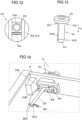
- an insert 314 with a through-opening 3141 for the shaft 321 is arranged in the region of the first end 3111 of the sleeve 311.
- the insert 314 is disk-shaped and extends essentially perpendicular to the longitudinal axis L H of the sleeve 311.
- the through-opening 3141 enables the shaft 321 to be passed through the insert 314 along the longitudinal axis L H of the sleeve 311.
- the shaft 321 is held firmly in the through-opening 3141.
- the insert 314 is pre-tensioned by means of a spring element 315 transversely to the longitudinal axis L H of the sleeve 311 in order to improve the hold of the insert 314 in the sleeve 311.
- guide rails 316 are formed in the first radial projection 312, which also extend transversely to the longitudinal axis L H of the sleeve 311.
- the spring element 315 is first assembled and then the insert 314 is assembled, as shown in the Figures 10 and 11 shown.
- Figure 12 shows the fully assembled state of the spring element 315 and the insert 314 in the guide rails 316.
- the first radial projection 312 is covered with an attractively designed decorative cap 317 ( Figure 13 ).
- the device 3 has a braking device 318.
- the braking device 318 is attached to the frame 11 of the backrest 1, here for example by means of a screw 319.
- the braking device 318 encompasses (clamps) a section of the shaft 321 when the shaft 321 is arranged in the sleeve 311.
- the braking device 318 comprises a split pin 3181 with a plastic sheath 3182.
- the split pin 3181 extends in a plane transverse to the longitudinal axis Ls of the shaft 321.
- the plastic sheath 3182 serves to increase the frictional force (static friction, sliding friction) between the shaft 321 and the split pin 3181 and can thus brake a movement of the shaft 321 relative to the sleeve 311.
- the material of the split pin can be selected in such a way that the friction effect of the plastic coating is achieved.
Landscapes
- Chair Legs, Seat Parts, And Backrests (AREA)
- Chairs For Special Purposes, Such As Reclining Chairs (AREA)
Applications Claiming Priority (1)
| Application Number | Priority Date | Filing Date | Title |
|---|---|---|---|
| DE202020105584.4U DE202020105584U1 (de) | 2020-09-29 | 2020-09-29 | Vorrichtung zur Befestigung und zum Verstellen einer Kopfstütze |
Publications (3)
| Publication Number | Publication Date |
|---|---|
| EP3973822A1 EP3973822A1 (de) | 2022-03-30 |
| EP3973822B1 true EP3973822B1 (de) | 2024-08-21 |
| EP3973822C0 EP3973822C0 (de) | 2024-08-21 |
Family
ID=73747135
Family Applications (1)
| Application Number | Title | Priority Date | Filing Date |
|---|---|---|---|
| EP21199438.9A Active EP3973822B1 (de) | 2020-09-29 | 2021-09-28 | Vorrichtung zur befestigung und zum verstellen einer kopfstütze |
Country Status (3)
| Country | Link |
|---|---|
| EP (1) | EP3973822B1 (pl) |
| DE (1) | DE202020105584U1 (pl) |
| PL (1) | PL3973822T3 (pl) |
Family Cites Families (3)
| Publication number | Priority date | Publication date | Assignee | Title |
|---|---|---|---|---|
| DE102012100200A1 (de) * | 2012-01-11 | 2013-07-11 | Hettich Franke Gmbh & Co. Kg | Haltevorrichtung für eine Kopfstütze |
| CN205338310U (zh) * | 2015-12-11 | 2016-06-29 | 东莞市伟宏五金塑胶制品有限公司 | 自动回收头枕调节架 |
| DE202018104018U1 (de) * | 2018-07-12 | 2018-08-08 | Ciar S.P.A. | Verstellvorrichtung für eine Kopfstütze |
-
2020
- 2020-09-29 DE DE202020105584.4U patent/DE202020105584U1/de active Active
-
2021
- 2021-09-28 EP EP21199438.9A patent/EP3973822B1/de active Active
- 2021-09-28 PL PL21199438.9T patent/PL3973822T3/pl unknown
Also Published As
| Publication number | Publication date |
|---|---|
| PL3973822T3 (pl) | 2024-12-16 |
| EP3973822A1 (de) | 2022-03-30 |
| DE202020105584U1 (de) | 2020-11-25 |
| EP3973822C0 (de) | 2024-08-21 |
Similar Documents
| Publication | Publication Date | Title |
|---|---|---|
| EP0254808B1 (de) | Höhen- und neigungsverstellbare Kopfstütze mit mittlerem Fenster für Kraftfahrzeugsitze | |
| DE102013104692B4 (de) | Schwenkbeschlag für Sitz- und/oder Liegemöbel | |
| DE7825224U1 (de) | Arbeitsstuhl | |
| EP2622991B1 (de) | Lordosenstütze, Rückenlehne, Stuhl und Verfahren zum Einstellen einer Lordosenstütze | |
| DE29910250U1 (de) | Verstellbare Armlehne für einen Stuhl | |
| DE2419483C3 (de) | Sitzmöbel mit Nackenstatze | |
| DE3435478C2 (pl) | ||
| DE3109592C2 (pl) | ||
| EP3973822B1 (de) | Vorrichtung zur befestigung und zum verstellen einer kopfstütze | |
| DE19945585B4 (de) | Anordnung zur stufenweisen Verstellung einer Kopfstütze bei einem Kraftfahrzeugsitz | |
| EP2689692B1 (de) | Sitzmöbel, insbesondere Bürostuhl | |
| EP2868230B1 (de) | Höhenverstellungsvorrichtung und Stuhl mit einer solchen Höhenverstellungsvorrichtung | |
| DE102020124190B4 (de) | Mehrteiliger Beschlag für ein Sitz- und/oder Liegemöbel, Sitz und/oder Liegemöbel, Verfahren zur Benutzung und Verwendung des mehrteiligen Beschlags | |
| DE102011116943A1 (de) | Federbelasteter Gelenkbeschlag | |
| DE102024124993B3 (de) | Stuhl | |
| DE102024116237B4 (de) | Federungseinrichtung | |
| DE102024117619A1 (de) | Kopfstütze | |
| DE202004003502U1 (de) | Stützvorrichtung | |
| AT525218B1 (de) | Stuhl | |
| DE102008012508A1 (de) | Tragfuß für eine Wanne | |
| DE102019118988B4 (de) | Polstermöbel mit verstellbarer Rückenlehne und Verfahren zu dessen Herstellung | |
| DE20100661U1 (de) | Sitz-/Liegemöbel | |
| DE29617154U1 (de) | Polstersessel oder Polsterelement mit verstellbarem Sitz- und Rückenpolster | |
| EP3146867A1 (de) | Tragsäule zur halterung eines möbelteils | |
| EP4252589A1 (de) | Lehnenvorrichtung für ein sitz- und/oder liegemöbelstück |
Legal Events
| Date | Code | Title | Description |
|---|---|---|---|
| PUAI | Public reference made under article 153(3) epc to a published international application that has entered the european phase |
Free format text: ORIGINAL CODE: 0009012 |
|
| STAA | Information on the status of an ep patent application or granted ep patent |
Free format text: STATUS: THE APPLICATION HAS BEEN PUBLISHED |
|
| AK | Designated contracting states |
Kind code of ref document: A1 Designated state(s): AL AT BE BG CH CY CZ DE DK EE ES FI FR GB GR HR HU IE IS IT LI LT LU LV MC MK MT NL NO PL PT RO RS SE SI SK SM TR |
|
| STAA | Information on the status of an ep patent application or granted ep patent |
Free format text: STATUS: REQUEST FOR EXAMINATION WAS MADE |
|
| 17P | Request for examination filed |
Effective date: 20220916 |
|
| RBV | Designated contracting states (corrected) |
Designated state(s): AL AT BE BG CH CY CZ DE DK EE ES FI FR GB GR HR HU IE IS IT LI LT LU LV MC MK MT NL NO PL PT RO RS SE SI SK SM TR |
|
| P01 | Opt-out of the competence of the unified patent court (upc) registered |
Effective date: 20230522 |
|
| GRAP | Despatch of communication of intention to grant a patent |
Free format text: ORIGINAL CODE: EPIDOSNIGR1 |
|
| STAA | Information on the status of an ep patent application or granted ep patent |
Free format text: STATUS: GRANT OF PATENT IS INTENDED |
|
| RAP3 | Party data changed (applicant data changed or rights of an application transferred) |
Owner name: STEINPOL CENTRAL SERVICES SP. Z O.O. |
|
| INTG | Intention to grant announced |
Effective date: 20240326 |
|
| GRAS | Grant fee paid |
Free format text: ORIGINAL CODE: EPIDOSNIGR3 |
|
| GRAA | (expected) grant |
Free format text: ORIGINAL CODE: 0009210 |
|
| STAA | Information on the status of an ep patent application or granted ep patent |
Free format text: STATUS: THE PATENT HAS BEEN GRANTED |
|
| AK | Designated contracting states |
Kind code of ref document: B1 Designated state(s): AL AT BE BG CH CY CZ DE DK EE ES FI FR GB GR HR HU IE IS IT LI LT LU LV MC MK MT NL NO PL PT RO RS SE SI SK SM TR |
|
| REG | Reference to a national code |
Ref country code: GB Ref legal event code: FG4D Free format text: NOT ENGLISH |
|
| REG | Reference to a national code |
Ref country code: CH Ref legal event code: EP |
|
| REG | Reference to a national code |
Ref country code: DE Ref legal event code: R096 Ref document number: 502021004836 Country of ref document: DE |
|
| REG | Reference to a national code |
Ref country code: IE Ref legal event code: FG4D Free format text: LANGUAGE OF EP DOCUMENT: GERMAN |
|
| U01 | Request for unitary effect filed |
Effective date: 20240903 |
|
| P04 | Withdrawal of opt-out of the competence of the unified patent court (upc) registered |
Free format text: CASE NUMBER: APP_51801/2024 Effective date: 20240914 |
|
| U07 | Unitary effect registered |
Designated state(s): AT BE BG DE DK EE FI FR IT LT LU LV MT NL PT RO SE SI Effective date: 20240918 |
|
| U20 | Renewal fee for the european patent with unitary effect paid |
Year of fee payment: 4 Effective date: 20240926 |
|
| REG | Reference to a national code |
Ref country code: CH Ref legal event code: PK Free format text: BERICHTIGUNGEN |
|
| RIN2 | Information on inventor provided after grant (corrected) |
Inventor name: WUSSLER, ARTUR |
|
| P05 | Withdrawal of opt-out of the competence of the unified patent court (upc) changed |
Free format text: CASE NUMBER: APP_51801/2024 Effective date: 20240918 |
|
| PG25 | Lapsed in a contracting state [announced via postgrant information from national office to epo] |
Ref country code: NO Free format text: LAPSE BECAUSE OF FAILURE TO SUBMIT A TRANSLATION OF THE DESCRIPTION OR TO PAY THE FEE WITHIN THE PRESCRIBED TIME-LIMIT Effective date: 20241121 |
|
| PG25 | Lapsed in a contracting state [announced via postgrant information from national office to epo] |
Ref country code: GR Free format text: LAPSE BECAUSE OF FAILURE TO SUBMIT A TRANSLATION OF THE DESCRIPTION OR TO PAY THE FEE WITHIN THE PRESCRIBED TIME-LIMIT Effective date: 20241122 |
|
| PGFP | Annual fee paid to national office [announced via postgrant information from national office to epo] |
Ref country code: PL Payment date: 20240917 Year of fee payment: 4 |
|
| PG25 | Lapsed in a contracting state [announced via postgrant information from national office to epo] |
Ref country code: IS Free format text: LAPSE BECAUSE OF FAILURE TO SUBMIT A TRANSLATION OF THE DESCRIPTION OR TO PAY THE FEE WITHIN THE PRESCRIBED TIME-LIMIT Effective date: 20241221 |
|
| PG25 | Lapsed in a contracting state [announced via postgrant information from national office to epo] |
Ref country code: HR Free format text: LAPSE BECAUSE OF FAILURE TO SUBMIT A TRANSLATION OF THE DESCRIPTION OR TO PAY THE FEE WITHIN THE PRESCRIBED TIME-LIMIT Effective date: 20240821 |
|
| PG25 | Lapsed in a contracting state [announced via postgrant information from national office to epo] |
Ref country code: ES Free format text: LAPSE BECAUSE OF FAILURE TO SUBMIT A TRANSLATION OF THE DESCRIPTION OR TO PAY THE FEE WITHIN THE PRESCRIBED TIME-LIMIT Effective date: 20240821 Ref country code: RS Free format text: LAPSE BECAUSE OF FAILURE TO SUBMIT A TRANSLATION OF THE DESCRIPTION OR TO PAY THE FEE WITHIN THE PRESCRIBED TIME-LIMIT Effective date: 20241121 |
|
| PG25 | Lapsed in a contracting state [announced via postgrant information from national office to epo] |
Ref country code: RS Free format text: LAPSE BECAUSE OF FAILURE TO SUBMIT A TRANSLATION OF THE DESCRIPTION OR TO PAY THE FEE WITHIN THE PRESCRIBED TIME-LIMIT Effective date: 20241121 Ref country code: NO Free format text: LAPSE BECAUSE OF FAILURE TO SUBMIT A TRANSLATION OF THE DESCRIPTION OR TO PAY THE FEE WITHIN THE PRESCRIBED TIME-LIMIT Effective date: 20241121 Ref country code: IS Free format text: LAPSE BECAUSE OF FAILURE TO SUBMIT A TRANSLATION OF THE DESCRIPTION OR TO PAY THE FEE WITHIN THE PRESCRIBED TIME-LIMIT Effective date: 20241221 Ref country code: HR Free format text: LAPSE BECAUSE OF FAILURE TO SUBMIT A TRANSLATION OF THE DESCRIPTION OR TO PAY THE FEE WITHIN THE PRESCRIBED TIME-LIMIT Effective date: 20240821 Ref country code: GR Free format text: LAPSE BECAUSE OF FAILURE TO SUBMIT A TRANSLATION OF THE DESCRIPTION OR TO PAY THE FEE WITHIN THE PRESCRIBED TIME-LIMIT Effective date: 20241122 Ref country code: ES Free format text: LAPSE BECAUSE OF FAILURE TO SUBMIT A TRANSLATION OF THE DESCRIPTION OR TO PAY THE FEE WITHIN THE PRESCRIBED TIME-LIMIT Effective date: 20240821 |
|
| PG25 | Lapsed in a contracting state [announced via postgrant information from national office to epo] |
Ref country code: SM Free format text: LAPSE BECAUSE OF FAILURE TO SUBMIT A TRANSLATION OF THE DESCRIPTION OR TO PAY THE FEE WITHIN THE PRESCRIBED TIME-LIMIT Effective date: 20240821 |
|
| PG25 | Lapsed in a contracting state [announced via postgrant information from national office to epo] |
Ref country code: CZ Free format text: LAPSE BECAUSE OF FAILURE TO SUBMIT A TRANSLATION OF THE DESCRIPTION OR TO PAY THE FEE WITHIN THE PRESCRIBED TIME-LIMIT Effective date: 20240821 |
|
| PG25 | Lapsed in a contracting state [announced via postgrant information from national office to epo] |
Ref country code: SK Free format text: LAPSE BECAUSE OF FAILURE TO SUBMIT A TRANSLATION OF THE DESCRIPTION OR TO PAY THE FEE WITHIN THE PRESCRIBED TIME-LIMIT Effective date: 20240821 |
|
| REG | Reference to a national code |
Ref country code: CH Ref legal event code: PL |
|
| PLBE | No opposition filed within time limit |
Free format text: ORIGINAL CODE: 0009261 |
|
| STAA | Information on the status of an ep patent application or granted ep patent |
Free format text: STATUS: NO OPPOSITION FILED WITHIN TIME LIMIT |
|
| PG25 | Lapsed in a contracting state [announced via postgrant information from national office to epo] |
Ref country code: MC Free format text: LAPSE BECAUSE OF FAILURE TO SUBMIT A TRANSLATION OF THE DESCRIPTION OR TO PAY THE FEE WITHIN THE PRESCRIBED TIME-LIMIT Effective date: 20240821 |
|
| PG25 | Lapsed in a contracting state [announced via postgrant information from national office to epo] |
Ref country code: CH Free format text: LAPSE BECAUSE OF NON-PAYMENT OF DUE FEES Effective date: 20240930 |
|
| PG25 | Lapsed in a contracting state [announced via postgrant information from national office to epo] |
Ref country code: IE Free format text: LAPSE BECAUSE OF NON-PAYMENT OF DUE FEES Effective date: 20240928 |
|
| 26N | No opposition filed |
Effective date: 20250522 |
|
| PG25 | Lapsed in a contracting state [announced via postgrant information from national office to epo] |
Ref country code: CY Free format text: LAPSE BECAUSE OF FAILURE TO SUBMIT A TRANSLATION OF THE DESCRIPTION OR TO PAY THE FEE WITHIN THE PRESCRIBED TIME-LIMIT; INVALID AB INITIO Effective date: 20210928 |
|
| PG25 | Lapsed in a contracting state [announced via postgrant information from national office to epo] |
Ref country code: HU Free format text: LAPSE BECAUSE OF FAILURE TO SUBMIT A TRANSLATION OF THE DESCRIPTION OR TO PAY THE FEE WITHIN THE PRESCRIBED TIME-LIMIT; INVALID AB INITIO Effective date: 20210928 |