EP3973363B1 - Computer-implemented method for computer-aided generation of an executable control program for the control and/or regulation of a technical process - Google Patents
Computer-implemented method for computer-aided generation of an executable control program for the control and/or regulation of a technical process Download PDFInfo
- Publication number
- EP3973363B1 EP3973363B1 EP20723265.3A EP20723265A EP3973363B1 EP 3973363 B1 EP3973363 B1 EP 3973363B1 EP 20723265 A EP20723265 A EP 20723265A EP 3973363 B1 EP3973363 B1 EP 3973363B1
- Authority
- EP
- European Patent Office
- Prior art keywords
- input
- technical process
- state
- control program
- computer
- Prior art date
- Legal status (The legal status is an assumption and is not a legal conclusion. Google has not performed a legal analysis and makes no representation as to the accuracy of the status listed.)
- Active
Links
- 238000000034 method Methods 0.000 title claims description 90
- 230000008569 process Effects 0.000 title claims description 62
- 230000007704 transition Effects 0.000 claims description 15
- 230000001105 regulatory effect Effects 0.000 claims description 10
- 230000001276 controlling effect Effects 0.000 claims description 9
- 230000008859 change Effects 0.000 claims description 5
- 238000001514 detection method Methods 0.000 claims 2
- 238000004088 simulation Methods 0.000 claims 1
- 239000011159 matrix material Substances 0.000 description 11
- 238000004519 manufacturing process Methods 0.000 description 8
- 230000008901 benefit Effects 0.000 description 2
- 230000015556 catabolic process Effects 0.000 description 2
- 238000012544 monitoring process Methods 0.000 description 2
- 230000003213 activating effect Effects 0.000 description 1
- 238000010586 diagram Methods 0.000 description 1
- 238000001035 drying Methods 0.000 description 1
- 238000005516 engineering process Methods 0.000 description 1
- 238000004880 explosion Methods 0.000 description 1
- 230000006870 function Effects 0.000 description 1
- 239000007788 liquid Substances 0.000 description 1
- 238000003825 pressing Methods 0.000 description 1
Images

Classifications
-
- G—PHYSICS
- G05—CONTROLLING; REGULATING
- G05B—CONTROL OR REGULATING SYSTEMS IN GENERAL; FUNCTIONAL ELEMENTS OF SUCH SYSTEMS; MONITORING OR TESTING ARRANGEMENTS FOR SUCH SYSTEMS OR ELEMENTS
- G05B19/00—Programme-control systems
- G05B19/02—Programme-control systems electric
- G05B19/18—Numerical control [NC], i.e. automatically operating machines, in particular machine tools, e.g. in a manufacturing environment, so as to execute positioning, movement or co-ordinated operations by means of programme data in numerical form
- G05B19/4155—Numerical control [NC], i.e. automatically operating machines, in particular machine tools, e.g. in a manufacturing environment, so as to execute positioning, movement or co-ordinated operations by means of programme data in numerical form characterised by programme execution, i.e. part programme or machine function execution, e.g. selection of a programme
-
- G—PHYSICS
- G05—CONTROLLING; REGULATING
- G05B—CONTROL OR REGULATING SYSTEMS IN GENERAL; FUNCTIONAL ELEMENTS OF SUCH SYSTEMS; MONITORING OR TESTING ARRANGEMENTS FOR SUCH SYSTEMS OR ELEMENTS
- G05B19/00—Programme-control systems
- G05B19/02—Programme-control systems electric
- G05B19/04—Programme control other than numerical control, i.e. in sequence controllers or logic controllers
- G05B19/042—Programme control other than numerical control, i.e. in sequence controllers or logic controllers using digital processors
- G05B19/0426—Programming the control sequence
-
- G—PHYSICS
- G05—CONTROLLING; REGULATING
- G05B—CONTROL OR REGULATING SYSTEMS IN GENERAL; FUNCTIONAL ELEMENTS OF SUCH SYSTEMS; MONITORING OR TESTING ARRANGEMENTS FOR SUCH SYSTEMS OR ELEMENTS
- G05B13/00—Adaptive control systems, i.e. systems automatically adjusting themselves to have a performance which is optimum according to some preassigned criterion
-
- G—PHYSICS
- G05—CONTROLLING; REGULATING
- G05B—CONTROL OR REGULATING SYSTEMS IN GENERAL; FUNCTIONAL ELEMENTS OF SUCH SYSTEMS; MONITORING OR TESTING ARRANGEMENTS FOR SUCH SYSTEMS OR ELEMENTS
- G05B19/00—Programme-control systems
-
- G—PHYSICS
- G05—CONTROLLING; REGULATING
- G05B—CONTROL OR REGULATING SYSTEMS IN GENERAL; FUNCTIONAL ELEMENTS OF SUCH SYSTEMS; MONITORING OR TESTING ARRANGEMENTS FOR SUCH SYSTEMS OR ELEMENTS
- G05B19/00—Programme-control systems
- G05B19/02—Programme-control systems electric
- G05B19/04—Programme control other than numerical control, i.e. in sequence controllers or logic controllers
- G05B19/0405—Programme-control specially adapted for machine tool control and not otherwise provided for
-
- G—PHYSICS
- G06—COMPUTING; CALCULATING OR COUNTING
- G06F—ELECTRIC DIGITAL DATA PROCESSING
- G06F8/00—Arrangements for software engineering
- G06F8/30—Creation or generation of source code
- G06F8/34—Graphical or visual programming
-
- G—PHYSICS
- G06—COMPUTING; CALCULATING OR COUNTING
- G06F—ELECTRIC DIGITAL DATA PROCESSING
- G06F8/00—Arrangements for software engineering
- G06F8/40—Transformation of program code
- G06F8/41—Compilation
- G06F8/44—Encoding
-
- G—PHYSICS
- G05—CONTROLLING; REGULATING
- G05B—CONTROL OR REGULATING SYSTEMS IN GENERAL; FUNCTIONAL ELEMENTS OF SUCH SYSTEMS; MONITORING OR TESTING ARRANGEMENTS FOR SUCH SYSTEMS OR ELEMENTS
- G05B2219/00—Program-control systems
- G05B2219/20—Pc systems
- G05B2219/23—Pc programming
- G05B2219/23258—GUI graphical user interface, icon, function bloc editor, labview
-
- G—PHYSICS
- G05—CONTROLLING; REGULATING
- G05B—CONTROL OR REGULATING SYSTEMS IN GENERAL; FUNCTIONAL ELEMENTS OF SUCH SYSTEMS; MONITORING OR TESTING ARRANGEMENTS FOR SUCH SYSTEMS OR ELEMENTS
- G05B2219/00—Program-control systems
- G05B2219/30—Nc systems
- G05B2219/31—From computer integrated manufacturing till monitoring
- G05B2219/31372—Mes manufacturing execution system
-
- Y—GENERAL TAGGING OF NEW TECHNOLOGICAL DEVELOPMENTS; GENERAL TAGGING OF CROSS-SECTIONAL TECHNOLOGIES SPANNING OVER SEVERAL SECTIONS OF THE IPC; TECHNICAL SUBJECTS COVERED BY FORMER USPC CROSS-REFERENCE ART COLLECTIONS [XRACs] AND DIGESTS
- Y02—TECHNOLOGIES OR APPLICATIONS FOR MITIGATION OR ADAPTATION AGAINST CLIMATE CHANGE
- Y02P—CLIMATE CHANGE MITIGATION TECHNOLOGIES IN THE PRODUCTION OR PROCESSING OF GOODS
- Y02P90/00—Enabling technologies with a potential contribution to greenhouse gas [GHG] emissions mitigation
- Y02P90/30—Computing systems specially adapted for manufacturing
Definitions
- the invention relates to a computer-implemented method for the computer-assisted generation of an executable control program for controlling and/or regulating a technical process in which the functionality of the control program is defined using states, input signals and output signals using a user interface and is then converted into executable program code.
- system computers are used, to which a large number of input signals are fed.
- Such an input signal to the system computer can come, for example, from a position sensor that monitors the position of a piston in a cylinder, or from a temperature sensor that monitors the temperature of a liquid in a container, or a timer that dictates the duration of the drying time of a product .
- a technical process has a large number of input signals, output signals, states and error conditions as process variables, with a very simple technical process being influenced by a large number of these process variables. The more technical components that have to be controlled or regulated by a technical process, the greater the number of process variables that the technical process has.
- EP 0 707 248 A1 discloses another method for the computer-assisted generation of an executable control program, in which a graphical user interface is also used to define the functionality of the technical process.
- a graphical user interface is also used to define the functionality of the technical process.
- certain groups of graphical objects are assigned to a "view" by means of program attributes, whereby the group of graphical objects can be shown or hidden by activating or deactivating the respective program attribute.
- a classic line/table-like display of the user interface is said to be disadvantageous, as it is said to provide too little clarity.
- Another disadvantage of this method is that when the control program generated by the method for controlling or regulating the technical process was run, unexpected error conditions occurred, which led to failures in the technical process and consequently to failures in production .
- US 2015/0018977 A1 discloses a further method for the computer-assisted generation of an executable control program, in which states and state transitions are defined according to a table.
- the known method only describes selected states and does not allow for a complete monitoring of error states, which is disadvantageous.
- the object of the present invention is to create a computer-implemented method for the computer-aided generation of an executable control program for controlling and/or regulating a technical process, which method avoids the disadvantages of the prior art.
- the present object is achieved by the method steps of the method according to claim 1.
- the invention is based on the knowledge that in the known methods the user interfaces used to describe the technical process do not completely describe the process to be controlled or regulated with all its different states and all possible combinations of the input signals.
- the known user interfaces are suitable states and also state transitions of the technical process running as planned and also certain defined error states describe, but there always remain combinations of input signals or sequences of states that are not taken into account. Often the reason is that the engineer determining the engineering process is convinced that this condition or combination of input signals cannot possibly occur. As soon as the technical process has more than a few technical components, the reason is usually that the user interface does not provide any assistance in working through all possible combinations in a defined manner.
- each input signal is either constantly monitored with regard to a signal change or an error condition in accordance with the definition in an input table, or is defined as arbitrary and consequently not monitored.
- any deviation in the technical process is recognized immediately.
- the structure of the input table according to the invention for a complete description of the technical process enables a structured definition of all states and state transitions, which prevents certain input signal combinations from being considered in advance and then leading to a failure in production during the ongoing process, which is verified by a control table can.
- This innovative linking of technical parameters in the input table which contains all the information collected for a code generator for generating the control program for controlling the technical process, solves the technical problem of reducing downtimes in production processes, which makes the invention technical.
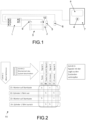
- FIG. 1 shows the technical components of a technical process controlled by a control program according to a first exemplary embodiment of the invention.
- a Control computer 1 is designed to process the control program in order to move a piston 2 of a cylinder 3 from a "rear” position to a "front” position and vice versa.
- the button 4 When the button 4 is pressed, it emits a first input signal E1 to the control computer 1. If a first sensor 5 detects the piston 2 in the “rear” position, then the first sensor 5 emits a second input signal E2 to the control computer 1 . When a second sensor 6 detects the piston 2 in the “front” position, the second sensor 6 emits a third input signal E3 to the control computer 1 .
- An input/output unit 7 has a display 8, the button 4 and other buttons (not shown) for entering information.
- the control computer 1 emits an output signal A1 to a first valve 9 in order to move the piston 2 from the "rear” position to the "front” position.
- the control computer 1 emits an output signal A2 to a second valve 10 in order to adjust the piston 2 from the "front” position to the "rear” position.
- figure 2 shows how, in a second step, from this definition of the course of the technical process in an input table 11, the course can be specified in a bit-oriented manner by means of inputs by a user.
- the four states Z1 to Z4 of the process are recorded in four rows of the input table 11 and the input signals E1 to E3 in the columns of the input table 11.
- the inverse first input signal is recorded as a further input signal in a separate column, since a long press on button 4 should not lead to an uncontrolled change in the position of piston 2 from "front” to "back” and back to "front”.
- the input signals E1 to E3 and are then combined with the logic to form the states.
- the user enters an "S" in a cell of the input table 11 if a signal change S has to be monitored in the respective state Z1 to Z4. So, for example, in the state Z1, when waiting for the input signal E1 of the key 4. Furthermore, the user enters an "I” in a cell of the input table 11 if the input signal has to be monitored in the respective state Z1 to Z4. So for example in the state Z1, when the input signal E2 must have the bit "1" in order to ensure that the piston is detected in the "rear” position. All other cells that are not filled with an "S” or an "I” by the user can have any value, i.e.
- the input signals E1 to E3 can have either the "0" bit or the "1" bit in these states " without having an impact on the course of the technical process.
- the identification by the letters "S” and "I” is of course only an example of an input option, which is why any letters or numbers or identifications can be used when filling the input table 11 by the user.
- control program For the computer-aided generation of an executable control program for the control computer 1, in order to allow the technical process described above to run under the control of the control computer 1, the control program is now generated by the control computer 1 or another computer based on the input table 11, the function of which is based on the work table 12 recognizable and can also be displayed on the display 8.
- the work table 12 shown contains the four states Z1 to Z4 in rows and the input signals E1 to E3 and in columns.
- bits "0" and "1" are inserted in the first section 13 of the work table 12 for the complete description of the functionality of the control program, whereby fields of the first section 13 of the work table 12 are also left blank if the Input signal according to the entries in the input table 11 can be arbitrary in this state.
- figure 3 shows the same as in the work table 12 according to the invention, in which the state transitions from one state to the following state were also included in four further lines of the work table 12.
- the output signals A1 and A2 of the control computer 1 to the valves 9 and 10 were also included in further columns.
- This first section 13 of the work table 12 describes all the inputs E1 to E3 and all the outputs A1 and A2 of the technical components of the system according to FIG figure 1 in all conceivable possible states of the system.
- the states Z1 to Z4 and the state transitions are assigned matrix bits Mx in four columns M1 to M4.
- the columns M1 to M4 correspond to the inputs E1, E4, E2 and E3, the bit “1” being represented in the matrix bits Mx in each case if this input signal is awaited in this state and the bit "0" being represented if the control computer 1 does not wait for this input signal in order to switch to the next state.
- a third section 15 of the work table 12 error states are recorded in accordance with the user input in the input table 11 and are monitored by the control program generated from this, which should lead to an error message on the display 8 in the respective state or state transition if there is a carried out by the control program cyclic comparison of the bits in the second section 14 and the third section 15 of the work table 12 to a discrepancy.
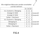
- This third section 15 of the work table 12 is filled in accordance with the user's entries in the input table 11 and can, with the aid of an in figure 4 illustrated control table 16 according to the invention are verified or controlled, which is discussed below.
- bit combinations of the three input signals E1 to E3 are listed in lines in control table 16, with the control computer or computer that creates the executable control program from input table 11 and/or work table 12 specifying for each of these bit combinations what this bit combination means .
- the bit combination 1 - 1 - 1 i.e. if all three input signals have a switching voltage, means that there must be a fault in the system, since the piston 2 is not simultaneously in the "rear" position from the first sensor 5 and from the second sensor 6 in the position "in front” can be detected.
- the same error state of the system is also present with the bit combination 0 - 1 - 1, since both input signals E2 and E2 also have switching voltage with this bit combination.
- This check table 16 is used by the user to check that every possible combination of the input signals E1 to E3 has actually been assigned a meaning or processing.
- a particularly reliable control program for controlling and/or regulating a technical process is obtained through this uninterrupted monitoring of all inputs of the system during every possible state or state transition.
- the technical process is brought into a defined state - for example the state Z1 - and the processing of the Control program started by the user.
- Parts of the work table 12 and optionally the control table 16 created by the control computer 1 or another computer when the control program is created can be displayed on the display 8 to inform the user before, during and also after processing the technical process.
- the input signal E2 of the first sensor 5 indicates that the piston 2 is not in the "back" position and therefore the status 1 is not present, then there is an error which is indicated to the user by means of the display 8 would become.
- the user can now see the status of the technical process and which sensor is delivering an unexpected sensor signal as an input signal.
- the error in the system can be easily recognized by the operator and eliminated, for example, by replacing the first sensor 5 .
- the matrix bit M1 shown as the "normal” font in the third section 15 is monitored to see whether it already has the bit "1", which indicates that the input signal E1 has a switching voltage when the button 4 is pressed. If this monitored switching condition WSB is detected by the control computer 1 by the bits specified in the "Transition to 2" line, then the control computer 1 switches to state 2 of the system and transmits the output signal A1 to the first valve 9, whereupon the Piston 2 moved to the "forward” position.
- the switching condition from state 2 to state 3 is reached when piston 2 has reached the "forward” position and the input signal E3 has a switching voltage, which corresponds to bit "1" in the monitored matrix bit M4 in the third section 15 of state Z2.
- the control table 16 enables the completeness of the bits entered in the work table 12 to be checked, but it would also be possible to create the work table 12 without it being checked by the control table 16 .
- the worktable 12 could of course also be created and used in reverse with regard to rows and columns.
- the states Z1 to Z4 would be noted in the columns and the input signals E1 to E3, the output signals A1 and A2 and the matrix bits Mx would be arranged in the rows.
- the advantage can also be achieved with this alternative arrangement that the technical process of the system is described in full in order to enable computer-aided generation of the executable program code to be processed with the control computer 1 .
- processing the program code for controlling and/or regulating the technical process it is thus ensured that all possible combinations of input signals lead to a specified processing. Whether it is a transition to the next state of the "state machine" or a defined error is displayed to the user, which enables an immediate solution based on the information in the table.
Landscapes
- Engineering & Computer Science (AREA)
- Physics & Mathematics (AREA)
- General Physics & Mathematics (AREA)
- Software Systems (AREA)
- Automation & Control Theory (AREA)
- General Engineering & Computer Science (AREA)
- Theoretical Computer Science (AREA)
- Computer Vision & Pattern Recognition (AREA)
- Artificial Intelligence (AREA)
- Evolutionary Computation (AREA)
- Medical Informatics (AREA)
- Health & Medical Sciences (AREA)
- Human Computer Interaction (AREA)
- Manufacturing & Machinery (AREA)
- Programmable Controllers (AREA)
- Debugging And Monitoring (AREA)
- Stored Programmes (AREA)
- User Interface Of Digital Computer (AREA)
Description
Die Erfindung betrifft ein computerimplementiertes Verfahren zur rechnergestützten Erzeugung eines ausführbaren Steuerungsprogramms zur Steuerung und/oder Regelung eines technischen Prozesses bei dem die Funktionalität des Steuerungsprogramms anhand von Zuständen, Eingangssignalen und Ausgangssignalen mittels einer Bedienoberfläche festgelegt und anschließend in ausführbaren Programmcode umgesetzt wird.The invention relates to a computer-implemented method for the computer-assisted generation of an executable control program for controlling and/or regulating a technical process in which the functionality of the control program is defined using states, input signals and output signals using a user interface and is then converted into executable program code.
Zur Steuerung oder Regelung eines technischen Prozesses in beispielsweise einer Produktionsanlage werden Systemrechner eingesetzt, denen eine Vielzahl an Eingangssignalen zugeführt werden. So ein Eingangssignal für den Systemrechner kann beispielsweise von einem Positionssensor kommen, der die Position eines Kolbens in einem Zylinder überwacht, oder von einem Temperatursensor, der die Temperatur einer Flüssigkeit in einem Behälter überwacht, oder einem Zeitgeber, der die Dauer der Trocknungszeit eines Produkts vorgibt. Ein technischer Prozess weist eine Vielzahl von Eingangssignalen, Ausgangssignalen, Zuständen und Fehlerbedingungen als Prozessvariablen auf, wobei bereits ein sehr einfacher technischer Prozess durch eine Mehrzahl dieser Prozessvariablen beeinflusst wird. Umso mehr technische Komponenten durch einen technischen Prozess gesteuert oder geregelt werden müssen, umso größer wird die Anzahl der Prozessvariablen, die der technische Prozess aufweist. Betrachtet man beispielsweise eine Raffinerie zur Herstellung von Benzin, dann wird unmittelbar klar wie viele Eingangssignale und Ausgangssignale die einzelnen technischen Komponenten der Raffinerie aufweisen und wie viele Zustände sie einnehmen können, wobei sich aus der Kombination aller Möglichkeiten dieser Prozessvariablen die beinahe unüberschaubar große Anzahl an geplanten und ungeplanten Abläufen des technischen Prozesses zur Herstellung von Benzin ergeben.To control or regulate a technical process in a production plant, for example, system computers are used, to which a large number of input signals are fed. Such an input signal to the system computer can come, for example, from a position sensor that monitors the position of a piston in a cylinder, or from a temperature sensor that monitors the temperature of a liquid in a container, or a timer that dictates the duration of the drying time of a product . A technical process has a large number of input signals, output signals, states and error conditions as process variables, with a very simple technical process being influenced by a large number of these process variables. The more technical components that have to be controlled or regulated by a technical process, the greater the number of process variables that the technical process has. If you look at a refinery for the production of gasoline, for example, it becomes immediately clear how many input and output signals the individual technical components of the refinery have and how many states they can assume, with the combination of all the possibilities of these process variables resulting in the almost unmanageably large number of planned and unplanned sequences of the technical process for the production of gasoline.
Es ist die Aufgabe der vorliegenden Erfindung ein computerimplementiertes Verfahren zur rechnergestützten Erzeugung eines ausführbaren Steuerungsprogramms zur Steuerung und/oder Regelung eines technischen Prozesses zu schaffen, welches die Nachteile des Standes der Technik vermeidet.The object of the present invention is to create a computer-implemented method for the computer-aided generation of an executable control program for controlling and/or regulating a technical process, which method avoids the disadvantages of the prior art.
Erfindungsgemäß wird die vorliegende Aufgabe durch die Verfahrensschritte des Verfahrens gemäß Anspruch 1 gelöst.According to the invention, the present object is achieved by the method steps of the method according to
Die Erfindung basiert auf der Erkenntnis, dass bei den bekannten Verfahren die benutzten Bedienoberflächen zur Beschreibung des technischen Prozesses den zu steuernden oder zu regelnden Prozess nicht zur Gänze mit all seinen unterschiedlichen Zuständen und allen Möglichkeiten an Kombinationen der Eingangssignale beschreiben. Die bekannten Bedienoberflächen sind geeignet Zustände und auch Zustandsübergänge des wie geplant ablaufenden technischen Prozesses und auch bestimmte definierte Fehlerzustände zu beschreiben, aber es verbleiben immer Kombinationen an Eingangssignalen oder Abfolgen von Zuständen, die nicht berücksichtigt werden. Oftmals ist der Grund, dass der den technischen Prozess festlegende Techniker davon überzeugt ist, dass es zu diesem Zustand oder dieser Kombination der Eingangssignale unmöglich kommen kann. Sobald der technische Prozess mehr als einige wenige technische Komponenten aufweist ist zumeist der Grund, dass die Bedienoberfläche keinerlei Hilfestellung liefert sämtlich mögliche Kombinationen definiert abzuarbeiten.The invention is based on the knowledge that in the known methods the user interfaces used to describe the technical process do not completely describe the process to be controlled or regulated with all its different states and all possible combinations of the input signals. The known user interfaces are suitable states and also state transitions of the technical process running as planned and also certain defined error states describe, but there always remain combinations of input signals or sequences of states that are not taken into account. Often the reason is that the engineer determining the engineering process is convinced that this condition or combination of input signals cannot possibly occur. As soon as the technical process has more than a few technical components, the reason is usually that the user interface does not provide any assistance in working through all possible combinations in a defined manner.
Die Erfindung löst diese Problematik dadurch, dass in jedem definierten Zustand jedes Eingangssignal entsprechend der Festlegung in einer Eingabetabelle entweder ständig bezüglich eines Signalwechsels oder einer Fehlerbedingung überwacht wird oder als beliebig festgelegt und folglich nicht überwacht wird. Hierdurch wird jede Abweichung des technischen Prozesses unmittelbar erkannt. Zusätzlich ermöglicht die erfindungsgemäße Struktur der Eingangstabelle zur vollständigen Beschreibung des technischen Prozesses eine strukturierte Festlegung aller Zustände und Zustandsübergänge, wodurch verhindert wird, dass bestimmte Eingangssignalkombinationen nicht vorab bedacht und im laufenden Prozess dann zu einem Ausfall in der Produktion führen, was durch eine Kontrolltabelle verifiziert werden kann. Durch diese neuartige Verknüpfung technischer Parameter in der Eingangstabelle, die sämtliche Informationen gesammelt für einen Code-Generator zur Erzeugung des Steuerungsprogramms zur Steuerung des technischen Prozesses enthält wird die technische Aufgabe zur Reduktion von Stillständen von Produktionsprozessen gelöst, wodurch die Technizität der Erfindung gegeben ist.The invention solves this problem in that, in each defined state, each input signal is either constantly monitored with regard to a signal change or an error condition in accordance with the definition in an input table, or is defined as arbitrary and consequently not monitored. As a result, any deviation in the technical process is recognized immediately. In addition, the structure of the input table according to the invention for a complete description of the technical process enables a structured definition of all states and state transitions, which prevents certain input signal combinations from being considered in advance and then leading to a failure in production during the ongoing process, which is verified by a control table can. This innovative linking of technical parameters in the input table, which contains all the information collected for a code generator for generating the control program for controlling the technical process, solves the technical problem of reducing downtimes in production processes, which makes the invention technical.
Weitere vorteilhafte Ausgestaltungen des erfindungsgemäßen Verfahrens werden nachfolgend anhand der Figuren erläutert.
-
Figur 1 -
Figur 2 -
Figur 3 -
Figur 4
-
figure 1 shows the technical components of a technical process controlled by a control program according to a first exemplary embodiment of the invention. -
figure 2 shows the steps according to the invention for the complete description of the technical process in an input table by input from a user. -
figure 3 shows a work table, which is at least partially displayed on display means and is filled from the input table. -
figure 4 shows a control table, which can also be displayed on the display means for checking the complete description of the technical process through the input table and the work table.
Der von diesem einfachen nur wenige technische Komponenten aufweisenden System abzuarbeitende Ablauf des technischen Prozesses kann in einem in Worten wie folgt beschrieben werden: Wenn der Kolben 2 auf der Position "hinten" steht und die Taste 4 gedrückt wird, dann gibt der Steuerrechner 1 das Ausgangssignal A1 an das erste Ventil 9 ab, worauf sich der Kolben 2 auf die Position "vorne" bewegt. Wenn der Kolben 2 auf der Position "vorne" steht und die Taste 4 gedrückt wird, dann gibt der Steuerrechner 1 das Ausgangssignal A2 an das zweite Ventil 10 ab, worauf sich der Kolben 2 auf die Position "hinten" bewegt. Dieser Ablauf des technischen Prozesses in Zuständen Z1 bis Z4 ist der erste Schritt zur vollständigen Beschreibung des Systems, wie dies in
Hierfür trägt der Benutzer ein "S" in eine Zelle der Eingabetabelle 11 ein, wenn in dem jeweiligen Zustand Z1 bis Z4 ein Signalwechsel S überwacht werden muss. Also beispielsweise im Zustand Z1, wenn auf das Eingangssignal E1 der Taste 4 gewartet wird. Weiters trägt der Benutzer ein "I" in eine Zelle der Eingabetabelle 11 ein, wenn in dem jeweiligen Zustand Z1 bis Z4 das Eingangssignal überwacht werden muss. Also beispielsweise im Zustand Z1, wenn das Eingangssignal E2 das Bit "1" aufweisen muss, um sicherzustellen, dass der Kolben in der Position "hinten" detektiert wird. Allen anderen Zellen, die nicht mit einem "S" oder einem "I" von dem Benutzer befüllt werden, können einen beliebigen Wert aufweisen, also die Eingangssignale E1 bis E3 können in diesen Zuständen sowohl das Bit "0" oder auch das Bit "1" aufweisen ohne, dass es einen Einfluss auf den Ablauf des technischen Prozesses hat. Die Kennzeichnung durch die Buchstaben "S" und "I" ist natürlich nur ein Beispiel einer Eingabemöglichkeit, weshalb beliebige Buchstaben oder Zahlen oder Kennzeichnungen bei der Befüllung der Eingabetabelle 11 durch den Benutzer verwendet werden können.For this purpose, the user enters an "S" in a cell of the input table 11 if a signal change S has to be monitored in the respective state Z1 to Z4. So, for example, in the state Z1, when waiting for the input signal E1 of the
Zur rechnergestützten Erzeugung eines ausführbaren Steuerungsprogramms für den Steuerungsrechner 1, um den vorstehend beschriebenen technischen Prozesses durch den Steuerungsrechner 1 gesteuert ablaufen zu lassen, wird nun durch den Steuerungsrechner 1 oder einen anderen Computer anhand der Eingabetabelle 11 das Steuerungsprogramm erzeugt, dessen Funktion anhand der Arbeitstabelle 12 erkennbar und auch an der Anzeige 8 anzeigbar ist. In einem ersten Abschnitt 13 der in
In einem zweiten Abschnitt 14 der Arbeitstabelle 12 sind den Zuständen Z1 bis Z4 und den Zustandsübergängen Matrixbits Mx in vier Spalten M1 bis M4 zugeordnet. Die Spalten M1 bis M4 entsprechen den Eingängen E1, E4, E2 und E3, wobei in den Matrixbits Mx jeweils das Bit "1" dargestellt ist, wenn in diesem Zustand auf dieses Eingangssignal gewartet wird, und das Bit "0" dargestellt ist, wenn der Steuerrechner 1 nicht auf dieses Eingangssignal wartet, um auf den nächsten Zustand weiterzuschalten.In a
In einem dritten Abschnitt 15 der Arbeitstabelle 12 sind entsprechend den Eingaben des Benutzers in der Eingabetabelle 11 Fehlerzustände festgehalten und werden durch das daraus erzeugte Steuerungsprogramm überwacht, die in dem jeweiligen Zustand oder Zustandsübergang zu einer Fehlermeldung an der Anzeige 8 führen sollen, wenn es bei einem durch das Steuerungsprogramm durchgeführten zyklischen Vergleich der Bits in dem zweiten Abschnitt 14 und dem dritten Abschnitt 15 der Arbeitstabelle 12 zu einer Diskrepanz kommt. Dieser dritte Abschnitt 15 der Arbeitstabelle 12 wird entsprechend den Eingaben des Benutzers in der Eingabetabelle 11 gefüllt und kann unter Zuhilfenahme einer in
In der Kontrolltabelle 16 sind alle möglichen Bitkombinationen der drei Eingangssignale E1 bis E3 in Zeilen angeführt, wobei von dem Steuerrechner oder Computer, der das ausführbare Steuerungsprogramm erstellt aus der Eingabetabelle 11 und/oder der Arbeitstabelle 12 zu jeder diese Bitkombinationen angibt, was diese Bitkombination bedeutet. So bedeutet die Bitkombination 1 - 1 - 1, also wenn alle drei Eingangssignale Schaltspannung aufweisen, dass ein Fehlerzustand des Systems vorliegen muss, da der Kolben 2 nicht gleichzeitig vom ersten Sensor 5 in der Position "hinten" und vom zweiten Sensor 6 in der Position "vorne" detektiert werden kann. Der gleiche Fehlerzustand des Systems liegt auch bei der Bitkombination 0 - 1 - 1 vor, da auch bei dieser Bitkombination beide Eingangssignale E2 und E2 Schaltspannung aufweisen. Diese Kontrolltabelle 16 dient dem Benutzer um zu kontrollieren, dass tatsächlich jeder nur möglichen Kombination der Eingangssignale E1 bis E3 auch eine Bedeutung beziehungsweise Verarbeitung zugeordnet wurde. Durch diese lückenlose Überwachung sämtlicher Eingänge des Systems während jedes nur möglichen Zustands oder Zustandsübergangs ist ein besonders zuverlässiges Steuerungsprogramm zur Steuerung und/oder Regelung eines technischen Prozesses erhalten.All possible bit combinations of the three input signals E1 to E3 are listed in lines in control table 16, with the control computer or computer that creates the executable control program from input table 11 and/or work table 12 specifying for each of these bit combinations what this bit combination means . The bit combination 1 - 1 - 1, i.e. if all three input signals have a switching voltage, means that there must be a fault in the system, since the
Nach dieser vollständigen Beschreibung der Funktionalität des technischen Prozesses durch manuelle Festlegung der Bits in der Eingabetabelle 11 kann die rechnergestützte Erzeugung des ausführbaren Steuerungsprogramms zur Steuerung und/oder Regelung des technischen Prozesses von dem Benutzer gestartet werden. Dem Fachmann ist dieses automatisierte Übersetzen einer durch eine Tabelle oder ein grafisches Modell beschriebenen Prozesses in ein ausführbares Steuerungsprogramm in Maschinensprache oder eine höhere Programmiersprache bekannt, wie dies beispielsweise in der
Im Folgenden wird der Ablauf des technischen Prozesses gesteuert durch den Steuerrechner 1 durch Abarbeitung des anhand der lückenlosen Beschreibung in der Arbeitstabelle 12 und der Kontrolltabelle 16 erzeugten Programmcodes erläutert. Im Zustand 1 befindet sich der Kolben 2 auf der Position "hinten", weshalb im ersten Abschnitt 13 nur das Eingangssignal E2 des ersten Sensors 5 das Bit "1" beziehungsweise Schaltspannung aufweist und im zweiten Abschnitt 14 das Matrixbit M1 das Bit "1" aufweist, da zum Weiterschalten auf Zustand 2 die Betätigung der Taste 4, also das Eingangssignal E1, erwartet wird. Im dritten Abschnitt 15 ist in der ersten Zeile zum Zustand 1 erkennbar, dass das als Font "fett" dargestellte Matrixbit M3 dahingehend überwacht wird, ob es das Bit "1" aufweist. Sollte Bit "0" vorliegen, also das Eingangssignal E2 des ersten Sensors 5 anzeigen, dass der Kolben 2 nicht in der Position "hinten" steht und somit nicht der Zustand 1 vorliegt, dann liegt ein Fehler vor, der mittels Anzeige 8 dem Benutzer angezeigt werden würde. Mit einem Blick auf die an der Anzeige 8 dargestellte Arbeitstabelle 12 kann der Benutzer nun erkennen in welchem Zustand sich der technische Prozess befindet und welcher Sensor ein unerwartetes Sensorsignal als Eingangssignal abgibt. Durch einen Blick auf die tatsächliche Position des Kolbens kann der Fehler des Systems von der Bedienperson leicht erkannt und beispielsweise durch Austausch des ersten Sensors 5 behoben werden.The sequence of the technical process controlled by the
Weiters wird im ersten Zustand Z1 das im dritten Abschnitt 15 als Font "normal" dargestellte Matrixbit M1 dahingehend überwacht, ob es bereits das Bit "1" aufweist, was ja anzeigt, dass das Eingangssignal E1 durch Drücken der Taste 4 Schaltspannung aufweist. Wenn diese überwachte Weiterschaltbedingung WSB vom Steuerrechner 1 durch die in der Zeile "Übergang auf 2" angegebenen Bits detektiert wird, dann schaltet der Steuerrechner 1 auf den Zustand 2 des Systems weiter und gibt das Ausgangssignal A1 an das erste Ventil 9 abgibt, worauf sich der Kolben 2 auf die Position "vorne" bewegt. Die Weiterschaltbedingung vom Zustand 2 auf den Zustand 3 ist dann erreicht, wenn der Kolben 2 die Position "vorne" erreicht hat und das Eingangssignal E3 Schaltspannung aufweist, was Bit "1" in dem überwachten Matrixbit M4 im dritten Abschnitt 15 des Zustands Z2 entspricht. Im Zustand 3 wird wiederum auf Eingangssignal E1 durch Tastendruck der Taste 4 gewartet, was Bit "1" in dem überwachten Matrixbit M1 im dritten Abschnitt 15 entspricht. Wenn die Taste 4 gedrückt wird, dann schaltet der Steuerrechner auf Zustand 4 weiter und gibt das Ausgangssignal A2 an das zweite Ventil 10 ab, worauf sich der Kolben 2 auf die Position "hinten" bewegt. Sobald der erste Sensor 5 das Eingangssignal E2 den Steuerrechner 1 abgibt, was durch das Bit "1" in dem überwachten Matrixbit M2 im dritten Abschnitt 15 detektiert wird, dann schaltet der Steuerrechner 1 wieder in den Zustand 1, wodurch der gesamte technische Prozess einmal durchlaufen wurde. Die Weiterschaltbedingungen WSB sind immer dadurch gekennzeichnet, dass sämtliche Matrixbits Mx in dem zweiten Abschnitt 14 der Arbeitstabelle 12 das Bit "0" aufweisen. In einer anderen Ausführungsvariante der Erfindung könnte die Weiterschaltbedingung WSB durch sämtliche Matrixbits Mx mit dem Bit "1" gekennzeichnet sein.Furthermore, in the first state Z1, the matrix bit M1 shown as the "normal" font in the
Die Kontrolltabelle 16 ermöglicht eine Kontrolle der Vollständigkeit der in die Arbeitstabelle 12 eingetragenen Bits, es wäre aber eine Erstellung der Arbeitstabelle 12 ohne deren Kontrolle durch die Kontrolltabelle 16 auch möglich.The control table 16 enables the completeness of the bits entered in the work table 12 to be checked, but it would also be possible to create the work table 12 without it being checked by the control table 16 .
Es kann erwähnt werden, dass die Arbeitstabelle 12 natürlich auch bezüglich Zeilen und Spalten umgekehrt erstellt und verwendet werden könnte. In diesem Fall wären die Zustände Z1 bis Z4 in den Spalten vermerkt und die Eingangssignale E1 bis E3, die Ausgangssignale A1 und A2 und die Matrixbits Mx in den Zeilen angeordnet. Auch mit dieser alternativen Anordnung kann der Vorteil erzielt werden, dass der technische Prozess des Systems vollumfänglich beschrieben wird, um eine rechnergestützte Erzeugung des mit dem Steuerrechner 1 abzuarbeitenden ausführbaren Programmcodes zu ermöglichen. Bei der Abarbeitung des Programmcodes zur Steuerung und/oder Regelung des technischen Prozesses ist somit sichergestellt, dass alle möglichen Kombinationen von Eingangssignalen zu einer festgelegten Verarbeitung führen. Sei es, dass auf den nächsten Zustand der "State Machine" übergegangen wird oder dem Benutzer ein definierter Fehler angezeigt wird, der anhand der Information in der Tabelle eine unmittelbare Lösung ermöglicht.It can be mentioned that the worktable 12 could of course also be created and used in reverse with regard to rows and columns. In this case, the states Z1 to Z4 would be noted in the columns and the input signals E1 to E3, the output signals A1 and A2 and the matrix bits Mx would be arranged in the rows. The advantage can also be achieved with this alternative arrangement that the technical process of the system is described in full in order to enable computer-aided generation of the executable program code to be processed with the
Das erfindungsgemäße Verfahren wurde vorstehend anhand eines sehr einfachen technischen Prozesses mit nur einem Zylinder 3 und einem Kolben 2, der nur in zwei Positionen verstellbar ist, erläutert. Sein eigentlicher Vorteil zeigt sich bei Anwendung der beschriebenen Vorgangsweise auf einen technischen Prozess mit einer Vielzahlt an unterschiedlichen technischen Einrichtungen, wie dies beispielsweise in einem halb- oder vollautomatischen Produktionsprozess gegeben ist.The method according to the invention was explained above using a very simple technical process with only one
Claims (5)
- A computer-implemented method for the computer-aided generation of an executable control program for controlling and/or regulating a technical process, in which the following method steps are implemented:defining the functionality of the control program by means of states (Z1 to Z4), input signals (E1 to E3), and output signals (A1, A2) via an operating interface;converting the determined functionality of the control program into an executable program code, characterized in that an input table (11) filled in via the user interface (7) fully describes the control program, wherein each state (Z1 to Z4) of the technical process is assigned a line/column of the input table (11) and each input signal (E1 to E3) of the technical process is assigned a column/line of the input table (11) in order to fully describe the technical process in the input table (11) by defining, in each cell of the input table (11),signal change (S) waiting for transition to next state, ormonitored (I) for error detection, orrandom,wherein in every defined state, every input signal is, according to the definition in the input table (11), either continuously monitored with regard to a signal change or an error condition, or randomly set and consequently not monitored by the program code, and wherein during the computer-aided creation of the executable control program from the input table (11) a check table (16) provides for all possible bit combinations of input signals (E1 to E3) information on which meaning or processing these bit combinations were assigned.
- The method of claim 1 characterized in that, during the creation of the executable control program from the input table (11), a working table (12) is created, in which every state (Z1 to Z4) of the technical process is assigned a line/column of the working table (12) and every input signal (E1 to E3) of the technical process is assigned a column/line in a first area (13) of the working table (12) in order to fully describe the technical process in the working table (12) by defining the expected input signals (Mx in 14) for the transition to the next state (Z1 to Z4) in a second area (14) of the working table (12) and by defining the monitored input signals (Mx in 15) for error detection in a third area (15) of the working table (12).
- The method of claim 2 characterized in that in further lines/columns of the working table (12) placed between the states (Z1 to Z4), one line each is provided for the transition from one state to the subsequent state, wherein the expected input signals (Mx in 14) must all have the bit zero or all have the bit one in these lines/columns.
- The method of any one of the claims 2 to 3 characterized in that each possible bit combination of input signals (E1 to E3) is assignable, in the control table (16), a state (Z1 to Z4) of the working table (12) or monitored error in the third area (15) of the working table (12) or transitions in the working table (12) in order to verify the full description of the technical process in the working table (12).
- The method of any one of the claims 2 to 4 characterized in that during a simulation of the control and/or regulation of the technical process by the control program based on the working table (12) with display means (8), the respectively next input signal (E1 to E3 as M1 to M4) will be marked that is expected for the transition of the current to the next state (Z 1 to Z4).
Applications Claiming Priority (2)
| Application Number | Priority Date | Filing Date | Title |
|---|---|---|---|
| ATA50458/2019A AT522186B1 (en) | 2019-05-20 | 2019-05-20 | Computer-implemented method for the computer-aided generation of an executable control program for controlling and / or regulating a technical process |
| PCT/AT2020/060169 WO2020232486A1 (en) | 2019-05-20 | 2020-04-27 | Computer-implemented method for computer-aided generation of an executable control program for the control and/or regulation of a technical process |
Publications (3)
| Publication Number | Publication Date |
|---|---|
| EP3973363A1 EP3973363A1 (en) | 2022-03-30 |
| EP3973363B1 true EP3973363B1 (en) | 2023-06-21 |
| EP3973363C0 EP3973363C0 (en) | 2023-06-21 |
Family
ID=70482222
Family Applications (1)
| Application Number | Title | Priority Date | Filing Date |
|---|---|---|---|
| EP20723265.3A Active EP3973363B1 (en) | 2019-05-20 | 2020-04-27 | Computer-implemented method for computer-aided generation of an executable control program for the control and/or regulation of a technical process |
Country Status (9)
| Country | Link |
|---|---|
| US (1) | US20220244709A1 (en) |
| EP (1) | EP3973363B1 (en) |
| JP (1) | JP7516423B2 (en) |
| KR (1) | KR20220011143A (en) |
| CN (1) | CN114144735B (en) |
| AT (1) | AT522186B1 (en) |
| CA (1) | CA3137626C (en) |
| ES (1) | ES2956267T3 (en) |
| WO (1) | WO2020232486A1 (en) |
Family Cites Families (38)
| Publication number | Priority date | Publication date | Assignee | Title |
|---|---|---|---|---|
| JPS5942884B2 (en) * | 1977-09-26 | 1984-10-18 | 横河電機株式会社 | Sequence control program debugging device |
| JP2539264B2 (en) * | 1989-04-07 | 1996-10-02 | 三菱電機株式会社 | Sequence controller |
| US5301100A (en) * | 1991-04-29 | 1994-04-05 | Wagner Ferdinand H | Method of and apparatus for constructing a control system and control system created thereby |
| JP3134428B2 (en) * | 1991-11-08 | 2001-02-13 | オムロン株式会社 | Failure diagnosis method and device |
| JP3275450B2 (en) * | 1993-04-30 | 2002-04-15 | オムロン株式会社 | Failure diagnosis method and device |
| EP0707248A1 (en) * | 1994-10-14 | 1996-04-17 | Siemens Aktiengesellschaft | Method for activating or deactivating parts of a program by means of views, controlled by program attributes, preferably for automation systems based on state graphs |
| JP2000270578A (en) * | 1999-03-18 | 2000-09-29 | Sony Corp | Control system and control method for motor |
| DE10017708B4 (en) * | 2000-04-04 | 2008-02-14 | Technische Universität Dresden | Method for controlling mechanisms and technical systems, equipment and control software |
| JP2003050607A (en) * | 2001-08-07 | 2003-02-21 | Mitsubishi Electric Corp | Programmable controller and its programming method and its program |
| JP2003177804A (en) * | 2001-09-28 | 2003-06-27 | Nippon Koei Power Systems Co Ltd | Method and device for generating sequence control program and program for making computer execute the same method |
| JP2003108220A (en) * | 2001-09-28 | 2003-04-11 | Omron Corp | System and method for assisting development of control program |
| JP4488701B2 (en) * | 2003-08-22 | 2010-06-23 | キヤノンソフトウェア株式会社 | PROGRAM GENERATION DEVICE, PROGRAM GENERATION METHOD, AND PROGRAM |
| US6968291B1 (en) * | 2003-11-04 | 2005-11-22 | Sun Microsystems, Inc. | Using and generating finite state machines to monitor system status |
| JP4874440B2 (en) * | 2004-06-29 | 2012-02-15 | 株式会社デンソー | PROGRAM GENERATION PROGRAM, PROGRAM GENERATION DEVICE, PROGRAM GENERATION METHOD, AND PROGRAM GENERATED BY THE SAME |
| DE102006059430A1 (en) * | 2006-12-15 | 2008-06-19 | Robert Bosch Gmbh | Automated creation and adaptation of a machine or plant model |
| JP4496205B2 (en) * | 2006-12-18 | 2010-07-07 | 日立オートモティブシステムズ株式会社 | Control microcomputer verification device and in-vehicle control device |
| JP2009175781A (en) * | 2008-01-21 | 2009-08-06 | Mitsubishi Denki Micom Kiki Software Kk | Program development support device |
| JP5087506B2 (en) * | 2008-09-16 | 2012-12-05 | 日晃オートメ株式会社 | Table arithmetic control unit |
| US20100174388A1 (en) * | 2009-01-02 | 2010-07-08 | Ferreira David A | Live Device Graphical Status Tree |
| CN102025312B (en) * | 2009-09-16 | 2014-01-29 | 株式会社东芝 | Motor control device and electrical equipment |
| EP2367083B1 (en) * | 2010-03-19 | 2016-10-05 | Sick Ag | Device for creating a program for a memory programmable control device, programming device and method for programming a memory programmable control device |
| CN103069386B (en) * | 2010-08-16 | 2016-06-22 | 三菱电机株式会社 | Control program creating device, control program generator and control program creating method |
| DE102010064337A1 (en) * | 2010-12-29 | 2012-07-05 | Winergy Ag | Method for controlling industrial manufacturing process for manufacturing gear boxes, involves registering status information of orders, and producing order controlling signal in empty table cell indicating maximum occupancy of station |
| JP5433638B2 (en) * | 2011-06-29 | 2014-03-05 | 合同会社IP Bridge1号 | Development support method and program |
| JP5463491B1 (en) * | 2012-11-09 | 2014-04-09 | 株式会社関東エルエンジニアリング | Automatic purge process control information generator |
| JP5907857B2 (en) * | 2012-12-05 | 2016-04-26 | 三菱電機株式会社 | Logic drawing and test table creation device |
| JP2014241072A (en) * | 2013-06-12 | 2014-12-25 | 日本電気通信システム株式会社 | Instruction generation device, instruction generation method, and instruction generation program |
| US9086688B2 (en) * | 2013-07-09 | 2015-07-21 | Fisher-Rosemount Systems, Inc. | State machine function block with user-definable actions on a transition between states |
| US10083627B2 (en) * | 2013-11-05 | 2018-09-25 | Lincoln Global, Inc. | Virtual reality and real welding training system and method |
| CN103699730B (en) * | 2013-12-18 | 2017-02-22 | 华侨大学 | Petri-net-based combined logic FPGA (Field Programmable Gate Array) system reachability graph generation method |
| EP3070553B1 (en) * | 2015-03-19 | 2019-05-08 | dSPACE digital signal processing and control engineering GmbH | Computer-implemented method for the computer-assisted translation of a graphic model describing the functionality of a control program |
| WO2017140363A1 (en) * | 2016-02-18 | 2017-08-24 | Nec Europe Ltd. | Time-guarded flow rule installation |
| JP6458754B2 (en) * | 2016-03-14 | 2019-01-30 | オムロン株式会社 | Program development support apparatus, program development support program, and program development support method |
| EP3246825A1 (en) * | 2016-05-20 | 2017-11-22 | cedalo GmbH | Controlling a device using tabular data |
| JP6532610B2 (en) * | 2016-08-30 | 2019-06-19 | 三菱電機株式会社 | Program editing apparatus, program editing method and program editing program |
| WO2018051441A1 (en) * | 2016-09-14 | 2018-03-22 | 三菱電機株式会社 | Ladder program editing assistance device and ladder program editing method |
| CN108572611B (en) * | 2017-03-13 | 2021-01-22 | 欧姆龙株式会社 | Information processing apparatus, information processing method, and computer-readable recording medium |
| JP7005914B2 (en) * | 2017-03-13 | 2022-01-24 | オムロン株式会社 | Information processing equipment, information processing methods, and information processing programs |
-
2019
- 2019-05-20 AT ATA50458/2019A patent/AT522186B1/en active
-
2020
- 2020-04-27 US US17/595,474 patent/US20220244709A1/en active Pending
- 2020-04-27 JP JP2021568876A patent/JP7516423B2/en active Active
- 2020-04-27 CN CN202080037379.7A patent/CN114144735B/en active Active
- 2020-04-27 CA CA3137626A patent/CA3137626C/en active Active
- 2020-04-27 KR KR1020217041106A patent/KR20220011143A/en unknown
- 2020-04-27 ES ES20723265T patent/ES2956267T3/en active Active
- 2020-04-27 EP EP20723265.3A patent/EP3973363B1/en active Active
- 2020-04-27 WO PCT/AT2020/060169 patent/WO2020232486A1/en unknown
Also Published As
| Publication number | Publication date |
|---|---|
| JP2022534479A (en) | 2022-08-01 |
| EP3973363A1 (en) | 2022-03-30 |
| ES2956267T3 (en) | 2023-12-18 |
| KR20220011143A (en) | 2022-01-27 |
| CN114144735A (en) | 2022-03-04 |
| US20220244709A1 (en) | 2022-08-04 |
| AT522186B1 (en) | 2020-09-15 |
| CA3137626A1 (en) | 2020-11-26 |
| EP3973363C0 (en) | 2023-06-21 |
| JP7516423B2 (en) | 2024-07-16 |
| CA3137626C (en) | 2023-10-24 |
| CN114144735B (en) | 2024-07-26 |
| AT522186A4 (en) | 2020-09-15 |
| WO2020232486A1 (en) | 2020-11-26 |
Similar Documents
| Publication | Publication Date | Title |
|---|---|---|
| EP1330685B1 (en) | Testing method and testing device for starting up systems which are controlled by means of a program logic | |
| EP2453326B1 (en) | Method and system for operating an automated machine | |
| DE102009011679A1 (en) | Method and device for creating a user program for a safety control | |
| EP3961317A2 (en) | Method for configuring a modular safety switching device | |
| DE102013100465A1 (en) | Microprocessor-controlled control device for an injection molding plant | |
| DE102017009429A1 (en) | Information processing apparatus | |
| DE102016011020A1 (en) | Ladder monitoring device with the ability to additionally display an operating situation of a CNC in a comment | |
| DE102005025673A1 (en) | Operating method for an evaluation device for a production machine | |
| EP3320431A1 (en) | Computer-implemented method for processing data object variants | |
| DE102015016489A1 (en) | Numerical control | |
| DE19614202C2 (en) | Method and device for controlling a machine tool, in particular a spark erosion machine | |
| DE102009019096A1 (en) | Safety control and method for controlling an automated plant | |
| EP3973363B1 (en) | Computer-implemented method for computer-aided generation of an executable control program for the control and/or regulation of a technical process | |
| EP1950635B1 (en) | Method for operating an automation system | |
| EP2037341B1 (en) | Programming system | |
| EP1430370B1 (en) | System and method for programming an automation system, based on pulse timing diagrams | |
| EP2449438B1 (en) | Method and system for driving at least one actuator | |
| EP1183577B1 (en) | Method for the production of an open-loop control block and said control block | |
| EP1998240B1 (en) | Control system with cyclical operation and method for incorporating software building blocks in the functional process of a control system | |
| EP3785091B1 (en) | Method for automatically generating labelled signatures | |
| DE102017121249A1 (en) | Method and system for machining a workpiece | |
| DE102019215488A1 (en) | Control system for a machine tool | |
| DE102019008515A1 (en) | INFORMATION PROCESSING DEVICE | |
| EP3779619A1 (en) | Emerging risks of a technical system | |
| EP1226473A2 (en) | Method for controlling mechanisms and technical systems, a corresponding device and control software |
Legal Events
| Date | Code | Title | Description |
|---|---|---|---|
| STAA | Information on the status of an ep patent application or granted ep patent |
Free format text: STATUS: UNKNOWN |
|
| STAA | Information on the status of an ep patent application or granted ep patent |
Free format text: STATUS: THE INTERNATIONAL PUBLICATION HAS BEEN MADE |
|
| PUAI | Public reference made under article 153(3) epc to a published international application that has entered the european phase |
Free format text: ORIGINAL CODE: 0009012 |
|
| STAA | Information on the status of an ep patent application or granted ep patent |
Free format text: STATUS: REQUEST FOR EXAMINATION WAS MADE |
|
| 17P | Request for examination filed |
Effective date: 20211015 |
|
| AK | Designated contracting states |
Kind code of ref document: A1 Designated state(s): AL AT BE BG CH CY CZ DE DK EE ES FI FR GB GR HR HU IE IS IT LI LT LU LV MC MK MT NL NO PL PT RO RS SE SI SK SM TR |
|
| DAV | Request for validation of the european patent (deleted) | ||
| REG | Reference to a national code |
Ref country code: HK Ref legal event code: DE Ref document number: 40073455 Country of ref document: HK |
|
| GRAP | Despatch of communication of intention to grant a patent |
Free format text: ORIGINAL CODE: EPIDOSNIGR1 |
|
| STAA | Information on the status of an ep patent application or granted ep patent |
Free format text: STATUS: GRANT OF PATENT IS INTENDED |
|
| INTG | Intention to grant announced |
Effective date: 20230125 |
|
| GRAS | Grant fee paid |
Free format text: ORIGINAL CODE: EPIDOSNIGR3 |
|
| GRAA | (expected) grant |
Free format text: ORIGINAL CODE: 0009210 |
|
| STAA | Information on the status of an ep patent application or granted ep patent |
Free format text: STATUS: THE PATENT HAS BEEN GRANTED |
|
| AK | Designated contracting states |
Kind code of ref document: B1 Designated state(s): AL AT BE BG CH CY CZ DE DK EE ES FI FR GB GR HR HU IE IS IT LI LT LU LV MC MK MT NL NO PL PT RO RS SE SI SK SM TR |
|
| REG | Reference to a national code |
Ref country code: CH Ref legal event code: EP |
|
| REG | Reference to a national code |
Ref country code: DE Ref legal event code: R096 Ref document number: 502020003880 Country of ref document: DE |
|
| REG | Reference to a national code |
Ref country code: AT Ref legal event code: REF Ref document number: 1581339 Country of ref document: AT Kind code of ref document: T Effective date: 20230715 |
|
| REG | Reference to a national code |
Ref country code: IE Ref legal event code: FG4D Free format text: LANGUAGE OF EP DOCUMENT: GERMAN |
|
| U01 | Request for unitary effect filed |
Effective date: 20230621 |
|
| U07 | Unitary effect registered |
Designated state(s): AT BE BG DE DK EE FI FR IT LT LU LV MT NL PT SE SI Effective date: 20230623 |
|
| REG | Reference to a national code |
Ref country code: LT Ref legal event code: MG9D |
|
| REG | Reference to a national code |
Ref country code: NO Ref legal event code: T2 Effective date: 20230621 |
|
| PG25 | Lapsed in a contracting state [announced via postgrant information from national office to epo] |
Ref country code: RS Free format text: LAPSE BECAUSE OF FAILURE TO SUBMIT A TRANSLATION OF THE DESCRIPTION OR TO PAY THE FEE WITHIN THE PRESCRIBED TIME-LIMIT Effective date: 20230621 Ref country code: HR Free format text: LAPSE BECAUSE OF FAILURE TO SUBMIT A TRANSLATION OF THE DESCRIPTION OR TO PAY THE FEE WITHIN THE PRESCRIBED TIME-LIMIT Effective date: 20230621 Ref country code: GR Free format text: LAPSE BECAUSE OF FAILURE TO SUBMIT A TRANSLATION OF THE DESCRIPTION OR TO PAY THE FEE WITHIN THE PRESCRIBED TIME-LIMIT Effective date: 20230922 |
|
| REG | Reference to a national code |
Ref country code: ES Ref legal event code: FG2A Ref document number: 2956267 Country of ref document: ES Kind code of ref document: T3 Effective date: 20231218 |
|
| PG25 | Lapsed in a contracting state [announced via postgrant information from national office to epo] |
Ref country code: SK Free format text: LAPSE BECAUSE OF FAILURE TO SUBMIT A TRANSLATION OF THE DESCRIPTION OR TO PAY THE FEE WITHIN THE PRESCRIBED TIME-LIMIT Effective date: 20230621 |
|
| PG25 | Lapsed in a contracting state [announced via postgrant information from national office to epo] |
Ref country code: IS Free format text: LAPSE BECAUSE OF FAILURE TO SUBMIT A TRANSLATION OF THE DESCRIPTION OR TO PAY THE FEE WITHIN THE PRESCRIBED TIME-LIMIT Effective date: 20231021 |
|
| PG25 | Lapsed in a contracting state [announced via postgrant information from national office to epo] |
Ref country code: SM Free format text: LAPSE BECAUSE OF FAILURE TO SUBMIT A TRANSLATION OF THE DESCRIPTION OR TO PAY THE FEE WITHIN THE PRESCRIBED TIME-LIMIT Effective date: 20230621 Ref country code: SK Free format text: LAPSE BECAUSE OF FAILURE TO SUBMIT A TRANSLATION OF THE DESCRIPTION OR TO PAY THE FEE WITHIN THE PRESCRIBED TIME-LIMIT Effective date: 20230621 Ref country code: RO Free format text: LAPSE BECAUSE OF FAILURE TO SUBMIT A TRANSLATION OF THE DESCRIPTION OR TO PAY THE FEE WITHIN THE PRESCRIBED TIME-LIMIT Effective date: 20230621 Ref country code: IS Free format text: LAPSE BECAUSE OF FAILURE TO SUBMIT A TRANSLATION OF THE DESCRIPTION OR TO PAY THE FEE WITHIN THE PRESCRIBED TIME-LIMIT Effective date: 20231021 Ref country code: CZ Free format text: LAPSE BECAUSE OF FAILURE TO SUBMIT A TRANSLATION OF THE DESCRIPTION OR TO PAY THE FEE WITHIN THE PRESCRIBED TIME-LIMIT Effective date: 20230621 |
|
| PG25 | Lapsed in a contracting state [announced via postgrant information from national office to epo] |
Ref country code: PL Free format text: LAPSE BECAUSE OF FAILURE TO SUBMIT A TRANSLATION OF THE DESCRIPTION OR TO PAY THE FEE WITHIN THE PRESCRIBED TIME-LIMIT Effective date: 20230621 |
|
| REG | Reference to a national code |
Ref country code: DE Ref legal event code: R097 Ref document number: 502020003880 Country of ref document: DE |
|
| PLBE | No opposition filed within time limit |
Free format text: ORIGINAL CODE: 0009261 |
|
| STAA | Information on the status of an ep patent application or granted ep patent |
Free format text: STATUS: NO OPPOSITION FILED WITHIN TIME LIMIT |
|
| 26N | No opposition filed |
Effective date: 20240322 |
|
| U20 | Renewal fee paid [unitary effect] |
Year of fee payment: 5 Effective date: 20240425 |
|
| PGFP | Annual fee paid to national office [announced via postgrant information from national office to epo] |
Ref country code: GB Payment date: 20240423 Year of fee payment: 5 |
|
| PGFP | Annual fee paid to national office [announced via postgrant information from national office to epo] |
Ref country code: CH Payment date: 20240501 Year of fee payment: 5 |
|
| PGFP | Annual fee paid to national office [announced via postgrant information from national office to epo] |
Ref country code: ES Payment date: 20240517 Year of fee payment: 5 |
|
| PGFP | Annual fee paid to national office [announced via postgrant information from national office to epo] |
Ref country code: NO Payment date: 20240419 Year of fee payment: 5 |