EP0707248A1 - Method for activating or deactivating parts of a program by means of views, controlled by program attributes, preferably for automation systems based on state graphs - Google Patents
Method for activating or deactivating parts of a program by means of views, controlled by program attributes, preferably for automation systems based on state graphs Download PDFInfo
- Publication number
- EP0707248A1 EP0707248A1 EP94116315A EP94116315A EP0707248A1 EP 0707248 A1 EP0707248 A1 EP 0707248A1 EP 94116315 A EP94116315 A EP 94116315A EP 94116315 A EP94116315 A EP 94116315A EP 0707248 A1 EP0707248 A1 EP 0707248A1
- Authority
- EP
- European Patent Office
- Prior art keywords
- program
- objects
- state
- transition
- application
- Prior art date
- Legal status (The legal status is an assumption and is not a legal conclusion. Google has not performed a legal analysis and makes no representation as to the accuracy of the status listed.)
- Withdrawn
Links
Images


Classifications
-
- G—PHYSICS
- G05—CONTROLLING; REGULATING
- G05B—CONTROL OR REGULATING SYSTEMS IN GENERAL; FUNCTIONAL ELEMENTS OF SUCH SYSTEMS; MONITORING OR TESTING ARRANGEMENTS FOR SUCH SYSTEMS OR ELEMENTS
- G05B19/00—Programme-control systems
- G05B19/02—Programme-control systems electric
- G05B19/04—Programme control other than numerical control, i.e. in sequence controllers or logic controllers
- G05B19/042—Programme control other than numerical control, i.e. in sequence controllers or logic controllers using digital processors
- G05B19/0426—Programming the control sequence
Landscapes
- Physics & Mathematics (AREA)
- General Physics & Mathematics (AREA)
- Engineering & Computer Science (AREA)
- Automation & Control Theory (AREA)
- Stored Programmes (AREA)
- Programmable Controllers (AREA)
Abstract
Description
Bei Automatisierungssystemen wird zunehmend das Verhalten eines technischen Systems bzw. eines Teiles davon mit Hilfe von graphischen Objekten einer graphischen Programmier-, Steuer- und Bedienoberfläche beschrieben und gesteuert. Diese werden z.B. als "Zustandsgraphen" bezeichnet und im Rahmen der nachfolgenden Beschreibung mit dem Begriff "Graph" abgekürzt. Ein solcher Graph hat den Vorteil, daß das stationäre und dynamische Verhalten eines technischen Systems, z.B. einer technischen Produktionsanlage, vollständig in Form einer übersichtlichen, geometrischen Darstellung visualisiert ist. Hiermit wird insbesondere die Projektierung, Programmierung, Kompilierung, Änderung, Dokumentation und der Ablauf von z.B. in der Praxis u.U. äußerst komplexen Steuerungen und Regelungen von technischen Prozessen erheblich erleichtert.In the case of automation systems, the behavior of a technical system or a part thereof is increasingly described and controlled with the aid of graphic objects from a graphic programming, control and user interface. These are e.g. referred to as "state graph" and abbreviated in the context of the following description with the term "graph". Such a graph has the advantage that the stationary and dynamic behavior of a technical system, e.g. a technical production system, completely visualized in the form of a clear, geometric representation. In particular, the project planning, programming, compilation, change, documentation and the process of e.g. in practice extremely complex controls and regulations of technical processes considerably easier.
Für die anwendungsabhängige Zusammenstellung eines Graphen stehen ausgewählte Typen graphischer Objekte zur Verfügung, die quasi als Bausteine dienen. Dies soll desweiteren am Beispiel von sogenannten Zustandsgraphen erläutert werden, bei denen die graphischen Objekte mit den Begriffen "Zustand", "Aktion", "Transition" und "Schaltbedingung" bezeichnet werden können. Ein Objekt vom Typ "Zustand" in einem Graphen repräsentiert dabei einen möglichen statischen Betriebszustand des dazugehörigen technischen Systems, z.B. einer technischen Produktionsanlage bzw. einem System zur Datenübertragung. Kann das technische System unterschiedliche Betriebszustände einnehmen, was in aller Regel der Fall ist, so ist für jeden dieser potentiellen Betriebszustände im Graph ein eigenes "Zustand" Objekt vorhanden. Diese bilden quasi die "Fixpunkte" eines das technische Gesamtsystem beschreibenden gesamten Graphen.For the application-dependent compilation of a graph, selected types of graphical objects are available, which serve as building blocks. This will also be explained using the example of so-called state graphs, in which the graphic objects can be designated with the terms "state", "action", "transition" and "switching condition". An object of the "state" type in a graph represents a possible static operating state of the associated technical system, for example a technical production system or a system for data transmission. If the technical system can assume different operating states, which is usually the case, then each of these potential operating states has its own "state" object in the graph. Form this quasi the "fixed points" of an entire graph describing the overall technical system.
Das dynamische Verhalten eines technischen Systems, d.h. die Verbindungen zwischen den als statische Fixpunkte ansehbaren "Zustand" Objekten, wird durch eine anwendungsabhängige Zusammenstellung von Objekten der Typen "Aktion", "Transition" und "Schaltbedingung" beschrieben. Dabei wird jeder "Zustand" durch eine "Aktion" aufrechterhalten. Im Graphen eines technisches Gesamtsystems ist somit einem jeden "Zustand" Objekt mindestens eine, diesen Anlagenzustand aufrechterhaltendes Objekt vom Typ "Aktion" zugeordnet. Übergange zwischen Zustanden, d.h. Ähderungen des Betriebszustandes von Betriebsmitteln der technischen Anlage, werden durch Objekte vom Typ "Transitionen" beschrieben. Zeichentechnisch werden diese in einem Graphen dargestellt durch eine pfeilartige Verbindung zwischen einem "Zustand" Objekt, welches den Startzustand der Anlage beschreibt, und einem "Zustand" Objekt, welches den Zielzustand der Anlage beschreibt. Jeder "Transition" ist schließlich ein Objekt vom Typ "Schaltbedingung" zugeordnet. Diese enthalt eine technische Ursache, bei deren Auftreten die dazugehörige "Transition", d.h. der entsprechende Zustandsubergang, aktiviert wird. Diese "Schaltbedingungen" werden bei technischen Anlagen durch Meßgeber, Sensoren oder Eingabegerate bereitgestellt. Sensoren signalisieren dabei automatisch die an speziellen Stellen der Anlage aktuell vorliegenden, gegebenenfalls umschaltrelevanten Prozeßbedingungen, während über Eingabegeräte vom Bedienpersonal der Anlage Schaltbedingungen vorgegebenen werden können.The dynamic behavior of a technical system, i.e. the connections between the "state" objects, which can be regarded as static fixed points, is described by an application-dependent combination of objects of the types "action", "transition" and "switching condition". Each "state" is maintained by an "action". In the graph of an overall technical system, therefore, each "state" object is assigned at least one object of the "action" type which maintains this system state. Transitions between states, i.e. Changes in the operating status of equipment in the technical system are described by objects of the "Transitions" type. In terms of drawing technology, these are represented in a graph by an arrow-like connection between a "state" object, which describes the start state of the system, and a "state" object, which describes the target state of the system. Finally, each "transition" is assigned an object of the "switching condition" type. This contains a technical cause, when it occurs the associated "transition", i.e. the corresponding state transition is activated. These "switching conditions" are provided in technical systems by sensors, sensors or input devices. Sensors automatically signal the process conditions that are currently present at special points in the system, possibly relevant for switchover, while switching conditions can be specified by the operating personnel of the system via input devices.
Technische Graphen der oben beschriebenen Art werden mit Datenverarbeitungsgeräten erstellt, bearbeitet und visualisiert. Als "Erstellsysteme" können hierfür bevorzugt Computersysteme eingesetzt werden, welche eine graphische Bedienoberfläche aufweisen. Für derartige Systeme eignen sich besonders sogenannte Engineering-Stations, herkömmliche PCs oder auch speicherprogrammierbare Steuerungen. Aus einem er-stellten, d.h. editierten, Graphen wird anschließend ein Steuerungsprogramm abgeleitet, welches auf einem sogenannten "Ablaufsystem" ausgeführt wird. Diese sind in der Regel Automatisierungssysteme, insbesondere Prozeßrechner, speicherprogrammierbare Steuerungen bzw. PCs, die zur Steuerung eines technischen Systems bzw. Prozesses dienen. Auch die programmtechnische Umsetzung, d.h. Kompilierung, eines Graphen in ein ablauffähiges Steuerungsprogramm z.B. für ein als Ablaufsystem dienendes Automatisierungssystem für eine technische Anlage kann vom Erstellsystem vorgenommen werden.Technical graphs of the type described above are created, processed and visualized with data processing devices. Computer systems which have a graphical user interface can preferably be used for this purpose as "creation systems". So-called engineering stations, conventional PCs, are particularly suitable for such systems or programmable logic controllers. A control program is then derived from a created, ie edited, graph, which is executed on a so-called "execution system". These are usually automation systems, in particular process computers, programmable logic controllers or PCs, which are used to control a technical system or process. The programming system can also implement, ie compile, a graph into an executable control program, for example for an automation system serving as an execution system for a technical system.
In Figur 1 ist eine derartige Anordnung symbolisch dargestellt. Als "Erstellsystem" ZGPS dient bevorzugt eine Engineering-Station, welche eine interaktive, graphische Erstellung eines Programms z.B. für eine als Ablaufsystem dienende Speicherprogrammierbare Steuerung SPS mit Hilfe von Zustandsgraphen ermöglicht. Die darin erstellte "Source" eines Zustandsgraphenprogramms wird bevorzugt im Erstellsystem ZGPS selbst zu einem auf dem Automatisierungssystem SPS ablauffähigen Steuerungsprogramm kompiliert. Das Programm wird über eine Kommunikationsverbindung KV1 vom Erstellsystem ZGPS zum Automatisierungssystem SPS übertragen. Als Automatisierungssysteme können z.B. die Steuerungen Sinumerik 840D oder Simatic S7 AS 300 der Firma SIEMENS eingesetzt werden.Such an arrangement is shown symbolically in FIG. An engineering station is preferably used as the "creation system" ZGPS, which enables an interactive, graphic creation of a program, e.g. for a programmable logic controller serving as a sequential control system with the help of status graphs. The "source" of a state graph program created therein is preferably compiled in the ZGPS creation system itself to form a control program that can run on the PLC automation system. The program is transferred from the ZGPS creation system to the PLC automation system via a communication link KV1. As automation systems e.g. the Sinumerik 840D or Simatic S7 AS 300 controls from SIEMENS are used.
Im Automatisierungssystem wird vom Steuerungsprogramm über einen internen P-Bus, eine Vielzahl von Ein- und Ausgabebaugruppen (E/A-Baugruppen) und eine weitere Kommunikationsschnittstelle KV2 auf die Prozeßperipherie zugegriffen. Hierbei handelt es sich um verteilt angebrachte Sensoren, Aktoren und Funktionseinheiten, welche die Funktion von analogen und binären Meßgebern und Stellgliedern aufweisen. Über diese Prozeßschnittstelle wird der technische Prozeß durch das im Erstellsystem ZGPS anwendungsabhängig editierte Zustandsgraphen- Steuerungsprogramm beeinflußt. Das Programm erfaßt die aktuellen Zustande von Meßgebern und Sensoren wie z.B. Lichtschranken, Bewegungsmeldern, Füllstandsanzeigen, Temperatursensoren und vielem mehr, und steuert abhängig davon Funktionseinheiten in der Fertigung und Stoffbearbeitung wie z.B. Motoren, Drehmaschinen, Fräsmaschinen, Fertigungsbänder, Hochregallager, Behälterfüllvorrichtungen, Temperaturregelungen, Mischer, Dosiersysteme und vieles mehr.In the automation system, the control program accesses the process peripherals via an internal P-bus, a large number of input and output modules (I / O modules) and a further communication interface KV2. These are distributed sensors, actuators and functional units, which have the function of analog and binary sensors and actuators. The technical process is influenced via this process interface by the state graph control program edited in the application system ZGPS depending on the application. The program records the Current status of sensors and sensors such as light barriers, motion detectors, level indicators, temperature sensors and much more, and depending on this controls functional units in production and fabric processing such as motors, lathes, milling machines, production lines, high-bay warehouses, container filling devices, temperature controls, mixers, dosing systems and much more more.
Trotz der in keiner Weise klassisch zeilen-/ tabellenartigen, sondern anschaulich flächigen, d.h. quasi zeichnerisch konstruktiven Darstellbarkeit der Strukturen eines Steuerungsprogrammes mit Hilfe der aus den Objekten zusammengesetzten Graphen, besteht doch auch bei diesen das Problem, daß deren Übersichtlichkeit besonders bei komplexen Steuerungsaufgaben an umfangreichen technischen Anlagen eingeschränkt ist. Durch die Vielzahl der dann vorhandenen Objekte und "Verästelungen" ist es nur schwer möglich, Teilfunktionen eines Zustandsgraph Steuerungsprogrammes bildende Teilprogramme zu erkennen. Derartige Teilfunktionen können z.B. der Normal-, Fehler-, Automatik- oder Handbetrieb einer dazugehörigen technischen Anlage sein. Jeder Teilfunktion wird durch ausgewählte Objekte, d.h. "Zustande" mit "Aktionen" und/oder "Transitionen" mit "Schaltbedingungen", realisiert. Eine jede Gruppe solcher Objekte bildet dann ein Teilprogramm.Despite the in no way classic line / table-like, but vividly flat, i.e. quasi graphically constructive representability of the structures of a control program with the help of the graphs composed of the objects, but there is also the problem with these that their clarity is restricted, particularly in the case of complex control tasks in extensive technical systems. Due to the large number of objects and "ramifications" that are then present, it is difficult to identify subroutines that form part functions of a state graph of a control program. Such sub-functions can e.g. the normal, fault, automatic or manual operation of an associated technical system. Each sub-function is represented by selected objects, i.e. "States" with "actions" and / or "transitions" with "switching conditions" implemented. Each group of such objects then forms a partial program.
Der Erfindung liegt die Aufgabe zu Grunde, eine anwendungsabhängige Aktivierung bzw. Deaktivierung von Teilprogrammen bei mittels graphischer Objekte beschriebenen technischen Systemen, insbesondere bei auf Zustandsgraphen basierenden Sternerungs- und Regelungsvorrichtungen, zu ermöglichen.The invention is based on the object of enabling application-dependent activation or deactivation of partial programs in technical systems described by means of graphic objects, in particular in startering and regulating devices based on state graphs.
Die Aufgabe wird gelöst mit dem im Anspruch 1 angegebenen Verfahren. Vorteilhafte weitere Ausführungsformen derselben sind in den nachfolgenden Unteransprüchen angegeben.The object is achieved with the method specified in
Die Erfindung beruht auf dem Prinzip, daß die Aktivierung bzw. Deaktivierung von Teilprogrammen mit Hilfe von über Programmattributen gesteuerten "Sichten" ermöglicht wird. Voraussetzung hierfür ist, daß bei der Erstellung eines Gesamt-Programms, wobei eine Vielzahl von graphischen Objekten anwendungsabhängig miteinander in Wechselbeziehungen gebracht werden, ebenfalls jedem graphischen Objekt des Gesamtprogramms ein anwendungsabhängig ausgewähltes Programmattribut zugeordnet wird. Hiermit ist es nun möglich, für die Ausführung des Gesamtprogramms, insbesondere auf einem Automatisierungssystem, diejenigen graphischen Objekte, welche Programmattribute aufweisen, die in einer anwendungsabhängig aktuell ausgewählten Gruppe bestimmter Programmattribute enthalten sind, zu einer dazugehörigen sogenannten "Sicht" zusammenzufassen. Eine "Sicht" wird somit definiert durch eine anwendungsabhängige Auswahl von einem oder mehreren bzw. keinem Programmattribut. Eine derartige "Sicht" repräsentiert somit wegen der Zusammenfassung von anwendungsabhängig ausgewählten Objekten des Gesamtprogramms ein Teilprogramm desselben, was aktiviert bzw. deaktiviert werden kann.The invention is based on the principle that the activation or deactivation of partial programs is made possible by means of "views" controlled by program attributes. The prerequisite for this is that when an overall program is created, with a large number of graphical objects being brought into interdependency with one another depending on the application, a graphically selected application attribute is also assigned to each graphical object of the overall program. With this it is now possible, for the execution of the overall program, in particular on an automation system, to combine those graphical objects, which have program attributes, which are contained in a group of certain program attributes currently selected depending on the application, into an associated so-called "view". A "view" is thus defined by an application-dependent selection of one or more or no program attributes. Such a “view” thus represents a sub-program of the overall program because of the combination of application-dependent selected objects of the overall program, which can be activated or deactivated.
Die Erfindung hat somit den Vorteil, daß über derartige "Sichten" Teilgraphen von Zustandsgraphen definiert werden, welche wiederum Teilprogrammen eines Gesamtprogramms entsprechen. Als eine mögliche "Sicht" kann theoretisch jeder zulässige Teilgraph dienen. Ist z.B. im einem "Erstellsystem" für Graphen eine bestimmte "Sicht" aktiviert, so kann nur der zu dieser Sicht gehörende Teilgraph bearbeitet werden. Es werden nur die zu diesem Teilgraph gehörenden Objekte angezeigt, d.h. Zustände mit Aktionen und/oder Transitionen mit Schaltbedingungen. Nur diese graphischen Objekte können modifiziert werden. Dies hat den Vorteil, daß wegen der Deaktivierung aktuell nicht benötigter Teilprogramme die zum aktivierten Teilprogramm gehörigen graphischen Objekte übersichtlich vorliegen, und eine Bearbeitung derselben somit schnell und fehlerfrei möglich ist.The invention thus has the advantage that partial graphs of state graphs are defined via such “views”, which in turn correspond to partial programs of an overall program. In theory, any permissible subgraph can serve as a possible "view". If, for example, a certain "view" is activated in a "graph creation system", only the subgraph belonging to this view can be edited. Only the objects belonging to this subgraph are displayed, ie states with actions and / or transitions with switching conditions. Only these graphic objects can be modified. This has the advantage that, due to the deactivation of part programs that are not currently required, the graphic objects belonging to the activated part program are clearly available, and processing thereof is thus possible quickly and without errors.
Ist z.B. im einem "Ablaufsystem" für Graphen eine bestimmte "Sicht" aktiviert, so kann nur der zu dieser "Sicht" gehörende Teilgraph ausgeführt werden. Hier dient eine "Sicht" dazu, ein Teilprogramm eines Gesamtprogramms zu definieren. Da der gesamte Graph ein Steuerprogramm insbesondere für eine speicherprogrammierbare Steuerung repräsentiert, stellen die zu dem durch eine "Sicht" freigelegten Teilgraph gehörenden graphischen Objekte ein Teilprogramm für die Steuerung dar. Dies hat den Vorteil, daß mit Hilfe der Sichten auf einfache Weise vorübergehend aktuelle Teilprogramme eines Gesamtprogramms aktiviert bzw. deaktiviert werden können. Das erfindungsgemäße Konzept der über Programmattribute gesteuerten Sichten ist vorteilhaft für alle graphische Programmiersprachen im Anwendungsbereich der Automatisierungstechnik einsetzbar.Is e.g. If a certain "view" is activated in a "execution system" for graphs, only the subgraph belonging to this "view" can be executed. Here, a "view" serves to define a sub-program of an overall program. Since the entire graph represents a control program, in particular for a programmable logic controller, the graphical objects belonging to the subgraph exposed by a "view" represent a subprogram for the control. This has the advantage that the current view allows the subprograms to be temporarily updated in a simple manner of an overall program can be activated or deactivated. The concept according to the invention of the views controlled via program attributes can advantageously be used for all graphic programming languages in the field of automation technology.
Die Erfindung hat den Vorteil, daß aktuell relevante Aspekte eines Gesamtprogramms in Form von Teilprogrammen herausgefiltert und diese Teilprogramme dann aktiviert bzw. deaktiviert werden können. Diese Teilgraphen können z.B. auch für die Darstellung auf einem Monitor, für das Drucken von Dokumentationen, für die editierende Bearbeitung eines Graphen- Sternerungsprogrammes z.B. durch Hinzufügen, Ändern oder Löschen von Objekten u.v.m. herangezogen werden. Vorteilhaft wird aus den in einem Gesamtprogramm anwendungsabhängig miteinander in Wechselbeziehungen gebrachten graphischen Objekten automatisch ein insbesondere auf einem Automatisierungssystem ablauffähiger Programmcode generiert. Der Graph bildet dann die einzige und vollständige Basis für eine Programmgenerierung, ohne das weitere Zwischenschritte notwendig sind.The invention has the advantage that currently relevant aspects of an overall program are filtered out in the form of partial programs and these partial programs can then be activated or deactivated. These subgraphs can e.g. also for display on a monitor, for printing documentation, for editing a graph starter program, e.g. by adding, changing or deleting objects and much more be used. Advantageously, a program code that can be run in particular on an automation system is automatically generated from the graphic objects that are interrelated in an application depending on the application. The graph then forms the only and complete basis for program generation, without the need for further intermediate steps.
Die Erfindung und vorteilhafte Ausführungsformen derselben werden anhand der in den nachfolgend kurz erläuterten Figuren dargestellten Beispielen näher erläutert. Dabei zeigt
- Fig.1:
- das bereits erläuterte Blockschaltbild für eine Anordnung aus einem "Erstellsystem" für auf Zustandsgraphen basierende Steuerungsprogramme und einem als "Ablaufsystem" dienenden Automatisierungssystem,
- Fig.2:
- einen beispielhaften, gemäß der Erfindung mit Programmattributen versehenen einfachen Zustandsgraphen zur Automatisierung eines Motors,
- Fig.3a bis 3d:
-
die "Zustand" Objekte des Zustandsgraphen von Fig.2 mit den dazugehörigen, den jeweiligen "Zustand" aufrechterhaltenden "Aktion" Objekten, - Fig.4a bis 4f:
-
die "Transition" Objekte des Zustandsgraphen von Fig.2 mit den dazugehörigen, die jeweilige "Transition" verursachenden "Schaltbedingung" Objekten, - Fig.5:
- eine durch entsprechende Zuweisung und Aktivierung von Programmattributen gebildete erste "Sicht" des Zustandsgraphen von Fig.2, welche z.B. zur "Kundendokumentation" einsetzbar ist,
- Fig.6:
- eine durch entsprechende Zuweisung und Aktivierung von Programmattributen gebildete weitere "Sicht" des Zustandsgraphen von Fig.2, wodurch z.B. der "Normal" Betriebszustand des Motors gesteuert wird,
- Fig.7:
- eine durch entsprechende Zuweisung und Aktivierung von Programmattributen gebildete weitere "Sicht" des Zustandsgraphen von Fig.2, wodurch z.B. der "Fehler" Betriebszustand des Motors gesteuert wird,
- Fig.8:
- einen weiteren beispielhaften, gemäß der Erfindung die zusätzliche Programmattributen "Hand" und "Automatik" aufweisenden Zustandsgraphen zur Automatisierung eines motorgetriebenen Förderbandes, und
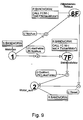
- Fig.9:
- eine durch entsprechende Zuweisung und Aktivierung von Programmattributen gebildete erste "Sicht" des Zustandsgraphen von Fig.8, wodurch z.B. der "Fehler" Betriebszustand des Bandes gesteuert wird, und
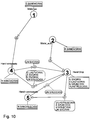
- Fig.10:
- eine durch entsprechende Zuweisung und Aktivierung von Programmattributen gebildete weitere "Sicht" des Zustandsgraphen von Fig.8, wodurch z.B. der "Hand" Betriebszustand des Bandes gesteuert wird, und
- Fig.1:
- the block diagram already explained for an arrangement of a "creation system" for control programs based on state graphs and an automation system serving as a "execution system",
- Fig. 2:
- an exemplary simple state graph for automating a motor, provided with program attributes according to the invention,
- 3a to 3d:
-
the “state” objects of the state graph of FIG. 2 with the associated “action” objects that maintain the respective “state”, - Fig.4a to 4f:
-
the "transition" objects of the state graph of FIG. 2 with the associated "switching condition" objects causing the respective "transition", - Fig. 5:
- a first "view" of the status graph from FIG. 2 formed by corresponding assignment and activation of program attributes, which can be used, for example, for "customer documentation",
- Fig. 6:
- a further "view" of the status graph of FIG. 2 formed by corresponding assignment and activation of program attributes, which controls, for example, the "normal" operating status of the engine,
- Fig. 7:
- a further "view" of the status graph of FIG. 2 formed by appropriate assignment and activation of program attributes, which, for example, controls the "error" operating state of the engine,
- Fig. 8:
- another exemplary, according to the invention the additional program attributes "hand" and "automatic" state graphs for the automation of a motor-driven conveyor belt, and
- Fig. 9:
- a first "view" of the state graph of FIG. 8 formed by corresponding assignment and activation of program attributes, thereby controlling, for example, the "error" operating state of the belt, and
- Fig. 10:
- a further "view" of the state graph of FIG. 8 formed by corresponding assignment and activation of program attributes, which controls, for example, the "manual" operating state of the belt, and
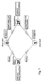
Figur 2 zeigt das typische Erscheinungsbild eines Zustandsgraphen, womit beispielhaft ein Motor automatisiert wird. Der Graph beschreibt vollständig alle stationären Zustände und das dynamische Verhalten des Motors. Bei Vorliegen eines entsprechend leistungsfähigen Systems kann der Zustandsgraph mit allen Objekten gegebenenfalls zugleich als Ablaufprogramm für eine den Motor beeinflussende speicherprogrammierbare Steuerung dienen. Andernfalls kann auf einfache Weise der Zustandsgraph in ein Ablaufprogramm für eine speicherprogrammierbare Steuerung umgesetzt werden. Üblicherweise müssen bei der Automatisierung eines Antriebs verschiedene Betriebszustände, insbesondere in Form von Betriebsarten des dazugehörigen Motors und Fehlerfällen, berücksichtigt werden.FIG. 2 shows the typical appearance of a state graph, which is used to automate an engine, for example. The graph fully describes all steady-state conditions and the dynamic behavior of the engine. If a correspondingly powerful system is present, the status graph with all objects can optionally also serve as a sequence program for a programmable logic controller influencing the motor. Otherwise, the state graph can be easily converted into a sequence program for a programmable logic controller. When operating a drive, various operating states, in particular in the form of operating modes of the associated motor and in the event of faults, usually have to be taken into account.
In der Praxis gibt es verschiedene Personen, die sich mit dem z.B. einen kleinen Teil einer technischen Anlage darstellenden Motor unter unterschiedlichen und zeitlich wechselnden Randbedingungen auseinandersetzen müssen. Dies sind z.B. der Automatisierungsingenieur während der Projektierungsphase, der Inbetriebsetzungsfachmann, der Wartungsfachmann und der sogenannte Werker der technischen Anlage, d.h. der Benutzer des automatisierten Motors. Nicht für jede Personengruppe sind alle Objekte im Gesamtgraphen von Fig.2 relevant. Um nun für die jeweilige Person relevante Teilprogramme aus diesem Graph separieren zu können, werden den vorhandenen graphischen Objekten erfindungsgemäß Programmattribute zugeordnet.In practice, there are different people who, with the motor, for example, representing a small part of a technical system, operate under different and changing times Have to deal with boundary conditions. These are, for example, the automation engineer during the project planning phase, the commissioning specialist, the maintenance specialist and the so-called worker of the technical system, ie the user of the automated motor. Not all objects in the overall graph of Fig. 2 are relevant for every group of people. In order to be able to separate sub-programs relevant to the respective person from this graph, program attributes are assigned to the existing graphic objects according to the invention.
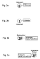
Der in Fig.2 dargestellte Graph besteht aus Objekten, welche im Falle des vorliegenden Zustandsgraphen dem Typ "Zustand", "Aktion", "Transition" und "Schaltbedingung" entsprechen. Hierzu sind in den Fig. 3a bis 3d die "Zustand" Objekte des Graphen von Fig.2 mit den dazugehörigen, den jeweiligen "Zustand" aufrechterhaltenden "Aktion" Objekten zusammengestellt. Ferner sind den "Zustand" Objekten zum besseren Verständnis Titel zugeordnet. So zeigt Fig.3a den ersten, mit "Motor steht" betitelten Zustand 0, zu dessen Aufrechterhaltung die "Aktion" RMotorAn, d.h. Rücksetze Motor an, ausgeführt werden muß. Fig. 3b zeigt den komplementären zweiten, mit "Motor läuft" betitelten Zustand 1, zu dessen Aufrechterhaltung die "Aktion" SMotorAn, d.h. Setze Motor an, ausgeführt werden muß. Fig. 3c zeigt eine dritten, mit "Betriebsfehler" betitelten Zustand 2F, zu dessen Aufrechterhaltung die "Aktionen" RMotorAn+MeldeFehlerMotor, d.h. Rücksetze Motor an und melde Motorfehler, ausgeführt werden müssen. Fig. 3d zeigt schließlich einen vierten, mit "Allgemeines Notaus" betitelten Zustand 3F, zu dessen Aufrechterhaltung die "Aktionen" RMotorAn+MeldeNotAusMotor,d.h. Rücksetze Motor an und melde Motornotabschaltung, ausgeführt werden müssen.The graph shown in FIG. 2 consists of objects which, in the case of the present state graph, correspond to the types "state", "action", "transition" and "switching condition". For this purpose, the “state” objects of the graph of FIG. 2 with the associated “action” objects that maintain the respective “state” are compiled in FIGS. 3a to 3d. Furthermore, titles are assigned to the "state" objects for better understanding. 3a shows the
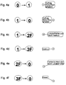
Ferner sind in den Figuren 4a bis 4f die "Transition" Objekte des Zustandsgraphen von Fig.2 mit den dazugehörigen, die jeweilige "Transition" verursachenden "Schaltbedingung" Objekten herausgestellt. So zeigt Fig. 4a als erste Transition den Übergang von Zustand 0 nach Zustand 1. Dieser wird ausgelöst, wenn die Schaltbedingung "AuftragMotorStarterhalten" vorliegt. Fig. 4b zeigt als weitere Transition den Übergang von Zustand 1 nach Zustand 0. Dieser wird ausgelöst, wenn die Schaltbedingung "AuftragMotorStarterhalten" vorliegt. Fig.4c zeigt die Transition von Zustand 1 nach Zustand 2F. Dieser wird ausgelöst, wenn die Schaltbedingung "Lokaler Fehler und NichtNotAus" vorliegt. Fig. 4d zeigt die Transition von Zustand 1 nach Zustand 3F. Dieser wird ausgelöst, wenn die Schaltbedingung "NotAus" vorliegt. Fig. 4e zeigt die Transition von Zustand 2F nach Zustand 0. Dieser wird ausgelöst, wenn die Schaltbedingung "Fehler quittiert und NichtLokaler Fehler" vorliegt. Fig. 4f zeigt schließlich die Transition von Zustand 3F nach Zustand 0. Dieser wird ausgelöst, wenn die Schaltbedingung "Reset" vorliegt.Furthermore, the “transition” objects of the state graph of FIG. 2 with the associated “switching condition” objects that cause the respective “transition” are shown in FIGS. 4a to 4f. 4a shows the first transition Transition from
Die Durchnummerierung der von einem Objekt vom Typ "Zustand" ausgehenden Objekte vom Typ "Transition" mit 0,1,2,3,... hat die Funktion einer Priorität. Hiermit sind den im Gesamtprogramm der Fig.2 anwendungsabhängig miteinander in Wechselbeziehungen stehenden graphischen Objekten eines Typs, insbesondere des Typs "Schaltbedingung", im Rahmen der Ausführung des dazugehörigen Gesamtprogramms eine zeitliche Bearbeitungsreihenfolge zugeordnet.The numbering of the objects of the type "Transition" starting from an object of the type "state" with 0,1,2,3, ... has the function of a priority. In this way, the graphical objects of one type, in particular of the "switching condition" type, which are interrelated in the application as a function of the application, are assigned a temporal processing sequence as part of the execution of the associated overall program.
Erfindungsgemäß wird nun jedem Objekt des Graphen von Fig.2, d.h. jedem "Zustand" und jeder "Transition", "Aktion" und "Schaltbedingung" ein sogenanntes "Programmattribut" zugeordnet. Im Beispiel der Figuren 2 bis 7 sind für "Zustände" und "Transitionen" die Programmattribute "Basis" und "Fehler" vorgesehen. So sind den Zuständen 0,1 und den Transitionen 0 nach 1 (1) und von 1 nach 0 (3), die keine weiteren Kennungen aufweisen, das Programmattribut "Basis" zugeordnet. Ferner sind den Zuständen 2F,3F und den Transitionen 1 nach 2F (1F), 1 nach 3F (2F), 3F nach 0 (1F) und 2F nach 0 (1F), erkennbar an der zusätzlichen Kennung F, das Programmattribut "Fehler" zugeordnet. Für Objekte der Typen "Aktion" und "Schaltbedingungen" ist das weitere Programmattribut "Sichtbar" vorgesehen. Es ergibt sich somit die folgende Tabelle:
Erfindungsgemäß wird eine "Sicht" aktiviert durch die anwendungsabhängige Auswahl von keinem, einem oder mehreren Programmattributen. In den Figuren 5,6,7 sind beispielhaft die "Sichten" von drei Teilprogrammen dargestellt.According to the invention, a "view" is activated by the application-dependent selection of none, one or more program attributes. The "views" of three partial programs are shown by way of example in FIGS. 5, 6, 7.
Die in Fig. 5 dargestellte "Sicht2" zeigt einen Teilgraphen, bei dem interne Details der Motorsteuerung deaktiviert sind, d.h. die Objekte vom Typ "Aktion" und "Schaltbedingung", und der im wesentlichen das äußere Verhalten des Motors beschreibt. Eine derartige Sicht ist somit als ein z.B. zur Kundendokumentation bzw. zu Vorführungszwecken dienendes Teilprogramm ausführbar. Die Fig. 6 "Sicht3" zeigt den Teilgraphen, in dem die das Verhalten des Motors im Normalbetrieb bestimmenden Objekte aktiviert sind, d.h. alle Objekte ohne das Programmattribut "Fehler". Es bildet somit ein mit "Normal" betitelbares, ohne weiteres in der Praxis auch ohne die in Fig.2 zusätzlich vorhandenen Objekte separat ausführbares Teilprogramm. Die Fig. 7 "Sicht4" zeigt schließlich den Teilgraphen, in dem die das Verhalten des Motors im Fehlerfalle bestimmenden Objekte aktiviert sind, d.h. alle Objekte ohne das Programmattribut "Basis". Es bildet somit ein mit "Fehler" betitelbares Teilprogramm. Auch dieses ist z.B. zu Testzwecken gegebenenfalls ohne die in Fig.2 zusätzlich vorhandenen Objekte separat ausführbar. Da die Fig. 2 den Gesamtgraphen der Motorsteuerung zeigt, der das statische und dynamische Verhalten des Motors vollständig beschreibt, kann dieser auch als eine mit "Alles" betitelbare "Sicht1" angesehen werden. Dieses "Teilprogramm", bei dem alle bei der beispielhaften Motorsteuerung vorhandenen Objekte aktiviert sind, ist selbstverständlich von einer speicherprogrammierbaren Steuerung separat ausführbar.The "
Die Sichten in den Figuren 2,5,6,7 können wie folgt zusammengefaßt werden ::
- Fig.2 :
- Sicht1 =
Σ Objekte mit Programmattributen (Basis, Fehler, Sichtbar) - Fig.5 :
- Sicht2 =
Σ Objekte mit Programmattributen (Basis, Fehler) - Fig.6 :
- Sicht3 =
Σ Objekte mit Programmattributen (Basis, Sichtbar) - Fig.7 :
- Sicht4 =
Σ Objekte mit Programmattributen (Fehler, Sichtbar) zuzüglich aller Zustand Objekte, die an ein derartiges Objekt grenzen, z.B. dieZustände
- Fig. 2:
- View1 =
Σ Objects with program attributes (base, error, visible) - Fig. 5:
- View2 =
Σ Objects with program attributes (basis, errors) - Fig. 6:
- View3 =
Σ Objects with program attributes (base, visible) - Fig. 7:
- View4 =
Σ Objects with program attributes (error, visible) plus all status objects that border on such an object,e.g. status
Grundsätzlich kann jeder Teilgraph bzw. das dazugehörige Teilprogramm eine mögliche "Sicht" bilden. Die Menge möglicher "Sichten" ist somit in keiner Weise auf die in den Figuren 2, 5 bis 7 dargestellten Beispiele beschränkt. Bevorzugt für den Einsatz in der Automatisierung von technischen Systemen und Prozessen können allgemein die folgenden Objekte eines Zustandsgraphen vorteilhaft zu einer "Sicht" zusammengefaßt werden:
- a) Menge aller Objekte vom Typ "Zustand", deren Programmattribute zur aktuell ausgewählten Menge von Programmattributen der Sicht gehören, z.B. alle "Zustände" mit den Programmattributen "Normal" und/oder "Fehler",
- b) zusätzlich die Menge aller Objekte vom Typ "Transition", deren Programmattribute zur aktuell ausgewählten Menge von Programmattributen der Sicht gehören, z.B. alle "Transitionen" mit den Programmattributen "Normal" und/oder "Fehler",
- c) zusätzlich die Menge aller Objekte vom Typ "Zustand", die Startknoten oder Endknoten von "Transitionen" darstellen, welche zu der unter b) definierten Auswahl von "Transitionen" gehören, und
- d) Für den Fall, daß zusätzlich das Programmattribut "Sichtbar" verfügbar ist: Alle "Aktionen" und "Schaltbedingungen", die Objekten vom Typ "Zustand" und "Transition" zugeordnet sind, welche zu einer unter a), b) oder c) definierten Auswahl von Objekten gehören.
- a) set of all objects of the "state" type whose program attributes belong to the currently selected set of program attributes in the view, for example all "states" with the program attributes "normal" and / or "error",
- b) additionally the set of all objects of the "Transition" type whose program attributes belong to the currently selected set of program attributes of the view, for example all "Transitions" with the program attributes "Normal" and / or "Error",
- c) additionally the set of all objects of the "state" type, which represent start nodes or end nodes of "transitions", which belong to the selection of "transitions" defined under b), and
- d) In the event that the "Visible" program attribute is also available: All "Actions" and "Switching conditions" are assigned to objects of the "State" and "Transition" type, which belong to one under a), b) or c ) include defined selection of objects.
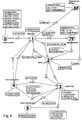
In Fig. 8 ist beispielhaft ein zur Automatisierung eines Förderbandes gehöriger komplexer Graph dargestellt. Dabei sind den "Zustand" Objekten 0,1,2,3,4,5 wiederum das Programmattribut "Basis", und den "Zustand" Objekten 6F,7F das Programmattribut "Fehler" zugeordnet. Entsprechend verfügen "Transition" Objekte ohne zusätzliche Kennung über das Programmattribut "Basis", und mit F markierte "Transition" Objekte, z.B. 1F,3F,4F über das Programmattribut "Fehler". Darüber hinausgehend sind für "Transition" Objekte die weiteren Programmattribute "Hand" und "Automatik" vorgesehen. Dies ist in Fig. 8 an zusätzlichen Kennungen H und A erkennbar. So sind drei "Transition" Objekten 1 das Programmattribut "Basis", zwei "Transition" Objekten 1A,3A das Programmattribut "Automatik", mehreren "Transition" Objekten 1H, 2H das Programmattribut "Hand" und mehreren "Transition" Objekten 1F,3F,4F das Programmattribut "Fehler" zugeordnet.FIG. 8 shows an example of a complex graph associated with the automation of a conveyor belt. The "status" objects 0,1,2,3,4,5 are in turn assigned the program attribute "base" and the "status" objects 6F, 7F the program attribute "error". Correspondingly, "Transition" objects without an additional identifier have the "Base" program attribute, and "Transition" objects marked with F,
Fig. 9 zeigt beispielhaft eine "Sicht", bei der alle mit dem Programmattribut "Fehler" versehene Objekte vom Typ "Zustand" und "Transition" aktiviert sind. Zusätzlich sind die "Zustand" Objekte 1,2 aktiviert, da diese einen Start- bzw. Endknoten für mit dem Programmattribut "Fehler" versehene Objekte vom Typ "Transition" bilden. Ferner sind alle Objekte vom Typ "Aktion" und "Schaltbedingung", welchen den oben genannten, aktivierten Objekten vom Typ "Zustand" und "Transition" zugeordnet sind, ebenfalls aktiviert.FIG. 9 shows an example of a “view” in which all objects of the “state” and “transition” type provided with the “error” program attribute are activated. In addition, the "state" objects 1, 2 are activated, since they form a start or end node for objects of the "Transition" type provided with the program attribute "error". Furthermore, all objects of the "action" and "switching condition" type, which are assigned to the above-mentioned activated objects of the "state" and "transition" type, are also activated.
Fig. 10 zeigt schließlich beispielhaft eine "Sicht", bei der alle mit dem Programmattribut "Hand" versehene Objekte vom Typ "Transition" aktiviert sind. Zusätzlich sind die "Zustand" Objekte 1,2,3,4,5 aktiviert, da diese einen Start- bzw. Endknoten für mit dem Programmattribut "Hand" versehene Objekte vom Typ "Transition" bilden. Ferner sind alle Objekte vom Typ "Aktion" und "Schaltbedingung", welchen den oben genannten, aktivierten Objekten vom Typ "Transition" und "Zustand" zugeordnet sind, ebenfalls aktiviert.10 finally shows an example of a "view" in which all objects of the "Transition" type provided with the program attribute "hand" are activated. In addition, the "Status" objects 1, 2, 3, 4, 5 are activated, since they form a start or end node for objects of the "Transition" type that have the "Hand" program attribute. Furthermore, all objects of the "action" and "switching condition" type, which are assigned to the above-mentioned activated objects of the "transition" and "state" type, are also activated.
Claims (4)
Priority Applications (2)
| Application Number | Priority Date | Filing Date | Title |
|---|---|---|---|
| EP94116315A EP0707248A1 (en) | 1994-10-14 | 1994-10-14 | Method for activating or deactivating parts of a program by means of views, controlled by program attributes, preferably for automation systems based on state graphs |
| US08/543,662 US5838974A (en) | 1994-10-14 | 1995-10-16 | Method for activating or rather deactivating subprograms using views controlled via program attributes in an automation system based preferably on state graphs |
Applications Claiming Priority (1)
| Application Number | Priority Date | Filing Date | Title |
|---|---|---|---|
| EP94116315A EP0707248A1 (en) | 1994-10-14 | 1994-10-14 | Method for activating or deactivating parts of a program by means of views, controlled by program attributes, preferably for automation systems based on state graphs |
Publications (1)
| Publication Number | Publication Date |
|---|---|
| EP0707248A1 true EP0707248A1 (en) | 1996-04-17 |
Family
ID=8216389
Family Applications (1)
| Application Number | Title | Priority Date | Filing Date |
|---|---|---|---|
| EP94116315A Withdrawn EP0707248A1 (en) | 1994-10-14 | 1994-10-14 | Method for activating or deactivating parts of a program by means of views, controlled by program attributes, preferably for automation systems based on state graphs |
Country Status (2)
| Country | Link |
|---|---|
| US (1) | US5838974A (en) |
| EP (1) | EP0707248A1 (en) |
Cited By (4)
| Publication number | Priority date | Publication date | Assignee | Title |
|---|---|---|---|---|
| WO2001029625A2 (en) * | 1999-10-15 | 2001-04-26 | Siemens Aktiengesellschaft | Method of drafting a program code of control and instrumentation technology |
| WO2002099548A1 (en) * | 2001-06-01 | 2002-12-12 | Siemens Aktiengesellschaft | Programming tool and method for creating programs, particularly for use in automation technology |
| DE102006044182A1 (en) * | 2006-09-15 | 2008-03-27 | Abb Patent Gmbh | System and method for the needs-based functionalization of control / regulating devices |
| AT522186A4 (en) * | 2019-05-20 | 2020-09-15 | Dipl Ing Dipl Ing Fh Markus Gruber | Computer-implemented method for the computer-aided generation of an executable control program for controlling and / or regulating a technical process |
Families Citing this family (5)
| Publication number | Priority date | Publication date | Assignee | Title |
|---|---|---|---|---|
| US6751787B1 (en) * | 2000-10-13 | 2004-06-15 | Intervoice Limited Partnership | Graphical programming language for representations of concurrent operations |
| US20020089772A1 (en) * | 2001-01-10 | 2002-07-11 | Rupert Gall | Automation system with a work drive unit |
| WO2006103541A1 (en) * | 2005-04-01 | 2006-10-05 | Abb Research Ltd | Method and system for providing a user interface |
| EP2407842B1 (en) * | 2010-07-16 | 2021-03-17 | Siemens Aktiengesellschaft | Method for operating machines or machines in a machine series and design system |
| EP2706419B1 (en) * | 2012-09-07 | 2019-12-04 | ABB Schweiz AG | Method and system for bay typical based IEC 61850 engineering and integration |
Citations (1)
| Publication number | Priority date | Publication date | Assignee | Title |
|---|---|---|---|---|
| DE4212370A1 (en) * | 1992-04-13 | 1993-10-14 | Siemens Ag | Programmable model for process plant network - has I=O modules coupled via path networks contg. range of functions selectable to create system |
Family Cites Families (4)
| Publication number | Priority date | Publication date | Assignee | Title |
|---|---|---|---|---|
| JPS62272366A (en) * | 1986-05-21 | 1987-11-26 | Hitachi Ltd | Graphic information processor |
| US5181162A (en) * | 1989-12-06 | 1993-01-19 | Eastman Kodak Company | Document management and production system |
| US5448727A (en) * | 1991-04-30 | 1995-09-05 | Hewlett-Packard Company | Domain based partitioning and reclustering of relations in object-oriented relational database management systems |
| JPH0728689A (en) * | 1993-07-09 | 1995-01-31 | Hitachi Ltd | Information processor |
-
1994
- 1994-10-14 EP EP94116315A patent/EP0707248A1/en not_active Withdrawn
-
1995
- 1995-10-16 US US08/543,662 patent/US5838974A/en not_active Expired - Fee Related
Patent Citations (1)
| Publication number | Priority date | Publication date | Assignee | Title |
|---|---|---|---|---|
| DE4212370A1 (en) * | 1992-04-13 | 1993-10-14 | Siemens Ag | Programmable model for process plant network - has I=O modules coupled via path networks contg. range of functions selectable to create system |
Non-Patent Citations (6)
| Title |
|---|
| "MODICON STATE LANGUAGE USER MANUAL", October 1993 |
| A.HERRSCHER: "FERTIGUNGSSYSTEME - ENTWURF UND REALISIERUNG PROZESSNAHER STEUERUNGSFUNKTIONEN", 1982, SPRINGER VERLAG, BERLIN |
| ALFRED FRIEDRICH: "Netz der Netze", ELEKTROTECHNIK, vol. 76, no. 4, 14 April 1994 (1994-04-14), WÜRZBURG,DE, pages 44 - 47, XP000447796 * |
| JOERG SCHNEIDER: "FEHLERREAKTIONEN MIT SPEICHERPROGRAMMIERBAREN STEUERUNGEN - EIN BEITRAG ZUR FEHLERTOLERANZ", 1994, SPRINGER VERLAG, ISBN: 3-540-58170-7 |
| LASTENHEFT SPS-CASE-TOOL VERSION 1.0, SEPTEMBER 1993 |
| RICHARD P. NEIDERT U.A.: "A new paradigm for industrial control system design", ISA TRANSACTIONS, vol. 32, no. 3, October 1993 (1993-10-01), AMSTERDAM,NL, pages 225 - 233, XP000404386 * |
Cited By (10)
| Publication number | Priority date | Publication date | Assignee | Title |
|---|---|---|---|---|
| WO2001029625A2 (en) * | 1999-10-15 | 2001-04-26 | Siemens Aktiengesellschaft | Method of drafting a program code of control and instrumentation technology |
| WO2001029625A3 (en) * | 1999-10-15 | 2001-10-25 | Siemens Ag | Method of drafting a program code of control and instrumentation technology |
| US7124122B1 (en) | 1999-10-15 | 2006-10-17 | Siemens Aktiengesellschaft | Method of drafting control and instrumentation technology |
| WO2002099548A1 (en) * | 2001-06-01 | 2002-12-12 | Siemens Aktiengesellschaft | Programming tool and method for creating programs, particularly for use in automation technology |
| DE102006044182A1 (en) * | 2006-09-15 | 2008-03-27 | Abb Patent Gmbh | System and method for the needs-based functionalization of control / regulating devices |
| CN101583913B (en) * | 2006-09-15 | 2013-09-25 | Abb专利有限公司 | System and method for functionalization in line with demand, for control and regulatory devices |
| US8644959B2 (en) | 2006-09-15 | 2014-02-04 | Abb Ag | System and method for functionalization in line with demand, for control and regulatory devices |
| AT522186A4 (en) * | 2019-05-20 | 2020-09-15 | Dipl Ing Dipl Ing Fh Markus Gruber | Computer-implemented method for the computer-aided generation of an executable control program for controlling and / or regulating a technical process |
| AT522186B1 (en) * | 2019-05-20 | 2020-09-15 | Dipl Ing Dipl Ing Fh Markus Gruber | Computer-implemented method for the computer-aided generation of an executable control program for controlling and / or regulating a technical process |
| WO2020232486A1 (en) | 2019-05-20 | 2020-11-26 | Markus Gruber | Computer-implemented method for computer-aided generation of an executable control program for the control and/or regulation of a technical process |
Also Published As
| Publication number | Publication date |
|---|---|
| US5838974A (en) | 1998-11-17 |
Similar Documents
| Publication | Publication Date | Title |
|---|---|---|
| EP1131686B1 (en) | Method for controlling technical processes | |
| EP2746883B1 (en) | Method and server for generating a display and control display for an operating and observation device of an industrial automation assembly | |
| EP0852759B1 (en) | Drafting method for industrial and building systems and computer-controlled planning system for use in said method | |
| EP2098926B1 (en) | Method and device for programming and/or configuring a safety controller | |
| WO2010060575A1 (en) | Method and device for creating a user program for a security control | |
| EP1184758A2 (en) | Method for debugging programs for industrial controllers, especially motion controllers, in the context of flow chart programmation | |
| EP2098925A1 (en) | Method and device for programming and/or configuring a safety controller | |
| WO2002065223A2 (en) | System for controlling and monitoring machines and/or systems with active components belonging to different active groups | |
| EP1402325B1 (en) | Method and system for assisting in the planning of manufacturing facilities | |
| EP0553621B1 (en) | Programmable computer control for a machine tool | |
| EP2098924A1 (en) | Method and device for programming and/or configuring a safety controller | |
| EP0707248A1 (en) | Method for activating or deactivating parts of a program by means of views, controlled by program attributes, preferably for automation systems based on state graphs | |
| AT412131B (en) | AUTOMATION SYSTEM FOR SOLVING A PROCESS TECHNICAL TASK AND METHOD FOR THIS | |
| DE202008017893U1 (en) | Device for programming and / or configuring a safety controller | |
| EP0862763B1 (en) | Simulator unit for simulating a peripheral unit of a modular programmable controller | |
| EP1221641A2 (en) | Industrial control with clock synchronised scheduling-model | |
| EP3969970A1 (en) | Method for displaying and operating production means, in particular for the plastics processing industry | |
| EP1183577A1 (en) | Method for the production of an open-loop control block and said control block | |
| EP1226473A2 (en) | Method for controlling mechanisms and technical systems, a corresponding device and control software | |
| BE1026752B1 (en) | Device and method for iterative and interactive project planning from an I / O station for an automation control | |
| EP2104885B1 (en) | Planning device and method for planning a technical installation | |
| DE10125384B4 (en) | Device and method for commissioning and diagnosis of control systems | |
| DE19834943B4 (en) | automation system | |
| EP2533148A1 (en) | Graphical editor for developing programs for process control based on templates and detecting the differences between hierarchical data structures | |
| DE10233211A1 (en) | Computer system for configuring automation device firmware, uses database with data model, input devices for data model entities and processor devices to create data packets |
Legal Events
| Date | Code | Title | Description |
|---|---|---|---|
| PUAI | Public reference made under article 153(3) epc to a published international application that has entered the european phase |
Free format text: ORIGINAL CODE: 0009012 |
|
| AK | Designated contracting states |
Kind code of ref document: A1 Designated state(s): AT CH DE ES FR GB IT LI SE |
|
| 17P | Request for examination filed |
Effective date: 19960520 |
|
| 17Q | First examination report despatched |
Effective date: 19970414 |
|
| STAA | Information on the status of an ep patent application or granted ep patent |
Free format text: STATUS: THE APPLICATION IS DEEMED TO BE WITHDRAWN |
|
| 18D | Application deemed to be withdrawn |
Effective date: 20020725 |