EP3973322B1 - Berichten von informationen in zusammenhang mit zeitanpassungen von sounding-referenzsignalen (srs) - Google Patents
Berichten von informationen in zusammenhang mit zeitanpassungen von sounding-referenzsignalen (srs) Download PDFInfo
- Publication number
- EP3973322B1 EP3973322B1 EP20730799.2A EP20730799A EP3973322B1 EP 3973322 B1 EP3973322 B1 EP 3973322B1 EP 20730799 A EP20730799 A EP 20730799A EP 3973322 B1 EP3973322 B1 EP 3973322B1
- Authority
- EP
- European Patent Office
- Prior art keywords
- reference signal
- uplink reference
- base station
- timing adjustment
- adjustment parameter
- Prior art date
- Legal status (The legal status is an assumption and is not a legal conclusion. Google has not performed a legal analysis and makes no representation as to the accuracy of the status listed.)
- Active
Links
Images


Classifications
-
- H—ELECTRICITY
- H04—ELECTRIC COMMUNICATION TECHNIQUE
- H04W—WIRELESS COMMUNICATION NETWORKS
- H04W24/00—Supervisory, monitoring or testing arrangements
- H04W24/10—Scheduling measurement reports ; Arrangements for measurement reports
-
- G—PHYSICS
- G01—MEASURING; TESTING
- G01S—RADIO DIRECTION-FINDING; RADIO NAVIGATION; DETERMINING DISTANCE OR VELOCITY BY USE OF RADIO WAVES; LOCATING OR PRESENCE-DETECTING BY USE OF THE REFLECTION OR RERADIATION OF RADIO WAVES; ANALOGOUS ARRANGEMENTS USING OTHER WAVES
- G01S13/00—Systems using the reflection or reradiation of radio waves, e.g. radar systems; Analogous systems using reflection or reradiation of waves whose nature or wavelength is irrelevant or unspecified
- G01S13/74—Systems using reradiation of radio waves, e.g. secondary radar systems; Analogous systems
- G01S13/76—Systems using reradiation of radio waves, e.g. secondary radar systems; Analogous systems wherein pulse-type signals are transmitted
- G01S13/767—Responders; Transponders
-
- H—ELECTRICITY
- H04—ELECTRIC COMMUNICATION TECHNIQUE
- H04L—TRANSMISSION OF DIGITAL INFORMATION, e.g. TELEGRAPHIC COMMUNICATION
- H04L5/00—Arrangements affording multiple use of the transmission path
- H04L5/003—Arrangements for allocating sub-channels of the transmission path
- H04L5/0048—Allocation of pilot signals, i.e. of signals known to the receiver
- H04L5/0051—Allocation of pilot signals, i.e. of signals known to the receiver of dedicated pilots, i.e. pilots destined for a single user or terminal
-
- H—ELECTRICITY
- H04—ELECTRIC COMMUNICATION TECHNIQUE
- H04W—WIRELESS COMMUNICATION NETWORKS
- H04W56/00—Synchronisation arrangements
- H04W56/004—Synchronisation arrangements compensating for timing error of reception due to propagation delay
- H04W56/0045—Synchronisation arrangements compensating for timing error of reception due to propagation delay compensating for timing error by altering transmission time
-
- H—ELECTRICITY
- H04—ELECTRIC COMMUNICATION TECHNIQUE
- H04W—WIRELESS COMMUNICATION NETWORKS
- H04W64/00—Locating users or terminals or network equipment for network management purposes, e.g. mobility management
-
- H—ELECTRICITY
- H04—ELECTRIC COMMUNICATION TECHNIQUE
- H04W—WIRELESS COMMUNICATION NETWORKS
- H04W72/00—Local resource management
- H04W72/20—Control channels or signalling for resource management
- H04W72/21—Control channels or signalling for resource management in the uplink direction of a wireless link, i.e. towards the network
-
- H—ELECTRICITY
- H04—ELECTRIC COMMUNICATION TECHNIQUE
- H04L—TRANSMISSION OF DIGITAL INFORMATION, e.g. TELEGRAPHIC COMMUNICATION
- H04L5/00—Arrangements affording multiple use of the transmission path
- H04L5/003—Arrangements for allocating sub-channels of the transmission path
- H04L5/0048—Allocation of pilot signals, i.e. of signals known to the receiver
- H04L5/005—Allocation of pilot signals, i.e. of signals known to the receiver of common pilots, i.e. pilots destined for multiple users or terminals
Definitions
- aspects of the disclosure relate generally to wireless communications.
- Wireless communication systems have developed through various generations, including a first-generation analog wireless phone service (1G), a second-generation (2G) digital wireless phone service (including interim 2.5G networks), a third-generation (3G) high speed data, Internet-capable wireless service and a fourth-generation (4G) service (e.g., LTE or WiMax).
- 1G first-generation analog wireless phone service
- 2G second-generation digital wireless phone service
- 3G third-generation high speed data
- Internet-capable wireless service e.g., LTE or WiMax
- 4G fourth-generation
- wireless communication systems including cellular and personal communications service (PCS) systems.
- PCS personal communications service
- Examples of known cellular systems include the cellular Analog Advanced Mobile Phone System (AMPS), and digital cellular systems based on code division multiple access (CDMA), frequency division multiple access (FDMA), time division multiple access (TDMA), the Global System for Mobile communication (GSM), etc.
- CDMA code division multiple access
- FDMA frequency division multiple access
- TDMA time division
- a fifth generation (5G) wireless standard also referred to as New Radio (NR)
- NR New Radio
- the 5G standard according to the Next Generation Mobile Networks Alliance, is designed to provide data rates of several tens of megabits per second to each of tens of thousands of users, with 1 gigabit per second to tens of workers on an office floor.
- Several hundreds of thousands of simultaneous connections should be supported in order to support large wireless deployments. Consequently, the spectral efficiency of 5G mobile communications should be significantly enhanced compared to the current 4G standard.
- signaling efficiencies should be enhanced and latency should be substantially reduced compared to current standards.
- Document 3GPP, R1-1905034 relates to UE & gNB measurements for NR Positioning.
- Document US 2014/185520 A1 discloses providing a processing delay estimate of an access point, or turnaround calibration function (TCF), associated with round trip time (RTT) measurements.
- TCF turnaround calibration function
- RTT round trip time
- Document 3GPP, R1-1905760 relates UE and gNB measurements for NR Positioning.
- sequences of actions to be performed by, for example, elements of a computing device. It will be recognized that various actions described herein can be performed by specific circuits (e.g., application specific integrated circuits (ASICs)), by program instructions being executed by one or more processors, or by a combination of both. Additionally, the sequence(s) of actions described herein can be considered to be embodied entirely within any form of non-transitory computer-readable storage medium having stored therein a corresponding set of computer instructions that, upon execution, would cause or instruct an associated processor of a device to perform the functionality described herein.
- ASICs application specific integrated circuits
- a UE may be any wireless communication device (e.g., a mobile phone, router, tablet computer, laptop computer, tracking device, wearable (e.g., smartwatch, glasses, augmented reality (AR) / virtual reality (VR) headset, etc.), vehicle (e.g., automobile, motorcycle, bicycle, etc.), Internet of Things (IoT) device, etc.) used by a user to communicate over a wireless communications network.
- a UE may be mobile or may (e.g., at certain times) be stationary, and may communicate with a radio access network (RAN).
- RAN radio access network
- the term “UE” may be referred to interchangeably as an "access terminal” or “AT,” a “client device,” a “wireless device,” a “subscriber device,” a “subscriber terminal,” a “subscriber station,” a “user terminal” or UT, a “mobile device,” a “mobile terminal,” a “mobile station,” or variations thereof.
- AT access terminal
- client device a “wireless device”
- subscriber device a “subscriber terminal”
- a “subscriber station” a “user terminal” or UT
- UEs can communicate with a core network via a RAN, and through the core network the UEs can be connected with external networks such as the Internet and with other UEs.
- external networks such as the Internet and with other UEs.
- other mechanisms of connecting to the core network and/or the Internet are also possible for the UEs, such as over wired access networks, wireless local area network (WLAN) networks (e.g., based on IEEE 802.11, etc.
- a base station may operate according to one of several RATs in communication with UEs depending on the network in which it is deployed, and may be alternatively referred to as an access point (AP), a network node, a NodeB, an evolved NodeB (eNB), a next generation eNB (ng-eNB), a New Radio (NR) Node B (also referred to as a gNB or gNodeB), etc.
- AP access point
- eNB evolved NodeB
- ng-eNB next generation eNB
- NR New Radio
- a base station may be used primarily to support wireless access by UEs, including supporting data, voice, and/or signaling connections for the supported UEs.
- a base station may provide purely edge node signaling functions while in other systems it may provide additional control and/or network management functions.
- a communication link through which UEs can send signals to a base station is called an uplink (UL) channel (e.g., a reverse traffic channel, a reverse control channel, an access channel, etc.).
- a communication link through which the base station can send signals to UEs is called a downlink (DL) or forward link channel (e.g., a paging channel, a control channel, a broadcast channel, a forward traffic channel, etc.).
- DL downlink
- forward link channel e.g., a paging channel, a control channel, a broadcast channel, a forward traffic channel, etc.
- traffic channel can refer to either an uplink / reverse or downlink / forward traffic channel.
- base station may refer to a single physical transmission-reception point (TRP) or to multiple physical TRPs that may or may not be co-located.
- TRP transmission-reception point
- the physical TRP may be an antenna of the base station corresponding to a cell (or several cell sectors) of the base station.
- base station refers to multiple co-located physical TRPs
- the physical TRPs may be an array of antennas (e.g., as in a multiple-input multiple-output (MIMO) system or where the base station employs beamforming) of the base station.
- MIMO multiple-input multiple-output
- the physical TRPs may be a distributed antenna system (DAS) (a network of spatially separated antennas connected to a common source via a transport medium) or a remote radio head (RRH) (a remote base station connected to a serving base station).
- DAS distributed antenna system
- RRH remote radio head
- the non-co-located physical TRPs may be the serving base station receiving the measurement report from the UE and a neighbor base station whose reference RF signals (or simply "reference signals”) the UE is measuring. Because a TRP is the point from which a base station transmits and receives wireless signals, as used herein, references to transmission from or reception at a base station are to be understood as referring to a particular TRP of the base station.
- a base station may not support wireless access by UEs (e.g., may not support data, voice, and/or signaling connections for UEs), but may instead transmit reference signals to UEs to be measured by the UEs, and/or may receive and measure signals transmitted by the UEs.
- a base station may be referred to as a positioning beacon (e.g., when transmitting signals to UEs) and/or as a location measurement unit (e.g., when receiving and measuring signals from UEs).
- An "RF signal” comprises an electromagnetic wave of a given frequency that transports information through the space between a transmitter and a receiver.
- a transmitter may transmit a single "RF signal” or multiple “RF signals” to a receiver.
- the receiver may receive multiple "RF signals” corresponding to each transmitted RF signal due to the propagation characteristics of RF signals through multipath channels.
- the same transmitted RF signal on different paths between the transmitter and receiver may be referred to as a "multipath” RF signal.
- an RF signal may also be referred to as a "wireless signal” or simply a “signal” where it is clear from the context that the term “signal” refers to a wireless signal or an RF signal.
- FIG. 1 illustrates an exemplary wireless communications system 100.
- the wireless communications system 100 (which may also be referred to as a wireless wide area network (WWAN)) may include various base stations 102 and various UEs 104.
- the base stations 102 may include macro cell base stations (high power cellular base stations) and/or small cell base stations (low power cellular base stations).
- the macro cell base station may include eNBs and/or ng-eNBs where the wireless communications system 100 corresponds to an LTE network, or gNBs where the wireless communications system 100 corresponds to a NR network, or a combination of both, and the small cell base stations may include femtocells, picocells, microcells, etc.
- the base stations 102 may collectively form a RAN and interface with a core network 170 (e.g., an evolved packet core (EPC) or a 5G core (5GC)) through backhaul links 122, and through the core network 170 to one or more location servers 172 (which may be part of core network 170 or may be external to core network 170).
- a core network 170 e.g., an evolved packet core (EPC) or a 5G core (5GC)
- EPC evolved packet core
- 5GC 5G core
- the base stations 102 may perform functions that relate to one or more of transferring user data, radio channel ciphering and deciphering, integrity protection, header compression, mobility control functions (e.g., handover, dual connectivity), inter-cell interference coordination, connection setup and release, load balancing, distribution for non-access stratum (NAS) messages, NAS node selection, synchronization, RAN sharing, multimedia broadcast multicast service (MBMS), subscriber and equipment trace, RAN information management (RIM), paging, positioning, and delivery of warning messages.
- the base stations 102 may communicate with each other directly or indirectly (e.g., through the EPC / 5GC) over backhaul links 134, which may be wired or wireless.
- the base stations 102 may wirelessly communicate with the UEs 104. Each of the base stations 102 may provide communication coverage for a respective geographic coverage area 110. In an aspect, one or more cells may be supported by a base station 102 in each geographic coverage area 110.
- a "cell” is a logical communication entity used for communication with a base station (e.g., over some frequency resource, referred to as a carrier frequency, component carrier, carrier, band, or the like), and may be associated with an identifier (e.g., a physical cell identifier (PCI), a virtual cell identifier (VCI), a cell global identifier (CGI)) for distinguishing cells operating via the same or a different carrier frequency.
- PCI physical cell identifier
- VCI virtual cell identifier
- CGI cell global identifier
- different cells may be configured according to different protocol types (e.g., machine-type communication (MTC), narrowband IoT (NB-IoT), enhanced mobile broadband (eMBB), or others) that may provide access for different types of UEs.
- MTC machine-type communication
- NB-IoT narrowband IoT
- eMBB enhanced mobile broadband
- a cell may refer to either or both of the logical communication entity and the base station that supports it, depending on the context.
- TRP is typically the physical transmission point of a cell
- the terms “cell” and “TRP” may be used interchangeably.
- the term “cell” may also refer to a geographic coverage area of a base station (e.g., a sector), insofar as a carrier frequency can be detected and used for communication within some portion of geographic coverage areas 110.
- While neighboring macro cell base station 102 geographic coverage areas 110 may partially overlap (e.g., in a handover region), some of the geographic coverage areas 110 may be substantially overlapped by a larger geographic coverage area 110.
- a small cell base station 102' may have a coverage area 110' that substantially overlaps with the geographic coverage area 110 of one or more macro cell base stations 102.
- a network that includes both small cell and macro cell base stations may be known as a heterogeneous network.
- a heterogeneous network may also include home eNBs (HeNBs), which may provide service to a restricted group known as a closed subscriber group (CSG).
- HeNBs home eNBs
- CSG closed subscriber group
- the communication links 120 between the base stations 102 and the UEs 104 may include uplink (also referred to as reverse link) transmissions from a UE 104 to a base station 102 and/or downlink (also referred to as forward link) transmissions from a base station 102 to a UE 104.
- the communication links 120 may use MIMO antenna technology, including spatial multiplexing, beamforming, and/or transmit diversity.
- the communication links 120 may be through one or more carrier frequencies. Allocation of carriers may be asymmetric with respect to downlink and uplink (e.g., more or less carriers may be allocated for downlink than for uplink).
- the wireless communications system 100 may further include a wireless local area network (WLAN) access point (AP) 150 in communication with WLAN stations (STAs) 152 via communication links 154 in an unlicensed frequency spectrum (e.g., 5 GHz).
- WLAN STAs 152 and/or the WLAN AP 150 may perform a clear channel assessment (CCA) or listen before talk (LBT) procedure prior to communicating in order to determine whether the channel is available.
- CCA clear channel assessment
- LBT listen before talk
- the small cell base station 102' may operate in a licensed and/or an unlicensed frequency spectrum. When operating in an unlicensed frequency spectrum, the small cell base station 102' may employ LTE or NR technology and use the same 5 GHz unlicensed frequency spectrum as used by the WLAN AP 150. The small cell base station 102', employing LTE / 5G in an unlicensed frequency spectrum, may boost coverage to and/or increase capacity of the access network.
- NR in unlicensed spectrum may be referred to as NR-U.
- LTE in an unlicensed spectrum may be referred to as LTE-U, licensed assisted access (LAA), or MulteFire.
- the wireless communications system 100 may further include a millimeter wave (mmW) base station 180 that may operate in mmW frequencies and/or near mmW frequencies in communication with a UE 182.
- Extremely high frequency (EHF) is part of the RF in the electromagnetic spectrum. EHF has a range of 30 GHz to 300 GHz and a wavelength between 1 millimeter and 10 millimeters. Radio waves in this band may be referred to as a millimeter wave.
- Near mmW may extend down to a frequency of 3 GHz with a wavelength of 100 millimeters.
- the super high frequency (SHF) band extends between 3 GHz and 30 GHz, also referred to as centimeter wave.
- the mmW base station 180 and the UE 182 may utilize beamforming (transmit and/or receive) over a mmW communication link 184 to compensate for the extremely high path loss and short range.
- one or more base stations 102 may also transmit using mmW or near mmW and beamforming. Accordingly, it will be appreciated that the foregoing illustrations are merely examples and should not be construed to limit the various aspects disclosed herein.
- Transmit beamforming is a technique for focusing an RF signal in a specific direction.
- a network node e.g., a base station
- transmit beamforming the network node determines where a given target device (e.g., a UE) is located (relative to the transmitting network node) and projects a stronger downlink RF signal in that specific direction, thereby providing a faster (in terms of data rate) and stronger RF signal for the receiving device(s).
- Transmit beams may be quasi-collocated, meaning that they appear to the receiver (e.g., a UE) as having the same parameters, regardless of whether or not the transmitting antennas of the network node themselves are physically collocated.
- the receiver e.g., a UE
- QCL relation of a given type means that certain parameters about a second reference RF signal on a second beam can be derived from information about a source reference RF signal on a source beam.
- the receiver can use the source reference RF signal to estimate the Doppler shift, Doppler spread, average delay, and delay spread of a second reference RF signal transmitted on the same channel.
- the receiver can use the source reference RF signal to estimate the Doppler shift and Doppler spread of a second reference RF signal transmitted on the same channel. If the source reference RF signal is QCL Type C, the receiver can use the source reference RF signal to estimate the Doppler shift and average delay of a second reference RF signal transmitted on the same channel. If the source reference RF signal is QCL Type D, the receiver can use the source reference RF signal to estimate the spatial receive parameter of a second reference RF signal transmitted on the same channel.
- the receiver uses a receive beam to amplify RF signals detected on a given channel.
- the receiver can increase the gain setting and/or adjust the phase setting of an array of antennas in a particular direction to amplify (e.g., to increase the gain level of) the RF signals received from that direction.
- a receiver is said to beamform in a certain direction, it means the beam gain in that direction is high relative to the beam gain along other directions, or the beam gain in that direction is the highest compared to the beam gain in that direction of all other receive beams available to the receiver. This results in a stronger received signal strength (e.g., reference signal received power (RSRP), reference signal received quality (RSRQ), signal-to-interference-plus-noise ratio (SINR), etc.) of the RF signals received from that direction.
- RSRP reference signal received power
- RSRQ reference signal received quality
- SINR signal-to-interference-plus-noise ratio
- Receive beams may be spatially related.
- a spatial relation means that parameters for a transmit beam for a second reference signal can be derived from information about a receive beam for a first reference signal.
- a UE may use a particular receive beam to receive one or more reference downlink reference signals (e.g., positioning reference signals (PRS), navigation reference signals (NRS), tracking reference signals (TRS), phase tracking reference signal (PTRS), cell-specific reference signals (CRS), channel state information reference signals (CSI-RS), primary synchronization signals (PSS), secondary synchronization signals (SSS), synchronization signal blocks (SSBs), etc.) from a base station.
- PRS positioning reference signals
- NSS navigation reference signals
- TRS tracking reference signals
- PTRS phase tracking reference signal
- CRS cell-specific reference signals
- CSI-RS channel state information reference signals
- PSS primary synchronization signals
- SSS secondary synchronization signals
- SSBs synchronization signal blocks
- the UE can then form a transmit beam for sending one or more uplink reference signals (e.g., uplink positioning reference signals (UL-PRS), sounding reference signal (SRS), demodulation reference signals (DMRS), PTRS, etc.) to that base station based on the parameters of the receive beam.
- uplink reference signals e.g., uplink positioning reference signals (UL-PRS), sounding reference signal (SRS), demodulation reference signals (DMRS), PTRS, etc.
- a "downlink" beam may be either a transmit beam or a receive beam, depending on the entity forming it. For example, if a base station is forming the downlink beam to transmit a reference signal to a UE, the downlink beam is a transmit beam. If the UE is forming the downlink beam, however, it is a receive beam to receive the downlink reference signal.
- an "uplink" beam may be either a transmit beam or a receive beam, depending on the entity forming it. For example, if a base station is forming the uplink beam, it is an uplink receive beam, and if a UE is forming the uplink beam, it is an uplink transmit beam.
- the frequency spectrum in which wireless nodes is divided into multiple frequency ranges, FR1 (from 450 to 6000 MHz), FR2 (from 24250 to 52600 MHz), FR3 (above 52600 MHz), and FR4 (between FR1 and FR2).
- the anchor carrier is the carrier operating on the primary frequency (e.g., FR1) utilized by a UE 104/182 and the cell in which the UE 104/182 either performs the initial radio resource control (RRC) connection establishment procedure or initiates the RRC connection re-establishment procedure.
- RRC radio resource control
- the primary carrier carries all common and UE-specific control channels, and may be a carrier in a licensed frequency (however, this is not always the case).
- a secondary carrier is a carrier operating on a second frequency (e.g., FR2) that may be configured once the RRC connection is established between the UE 104 and the anchor carrier and that may be used to provide additional radio resources.
- the secondary carrier may be a carrier in an unlicensed frequency.
- the secondary carrier may contain only necessary signaling information and signals, for example, those that are UE-specific may not be present in the secondary carrier, since both primary uplink and downlink carriers are typically UE-specific. This means that different UEs 104/182 in a cell may have different downlink primary carriers. The same is true for the uplink primary carriers.
- the network is able to change the primary carrier of any UE 104/182 at any time. This is done, for example, to balance the load on different carriers. Because a "serving cell” (whether a PCell or an SCell) corresponds to a carrier frequency / component carrier over which some base station is communicating, the term "cell,” “serving cell,” “component carrier,” “carrier frequency,” and the like can be used interchangeably.
- one of the frequencies utilized by the macro cell base stations 102 may be an anchor carrier (or "PCell") and other frequencies utilized by the macro cell base stations 102 and/or the mmW base station 180 may be secondary carriers ("SCells").
- PCell anchor carrier
- SCells secondary carriers
- the simultaneous transmission and/or reception of multiple carriers enables the UE 104/182 to significantly increase its data transmission and/or reception rates. For example, two 20 MHz aggregated carriers in a multi-carrier system would theoretically lead to a two-fold increase in data rate (i.e., 40 MHz), compared to that attained by a single 20 MHz carrier.
- the wireless communications system 100 may further include one or more UEs, such as UE 190, that connects indirectly to one or more communication networks via one or more device-to-device (D2D) peer-to-peer (P2P) links.
- UE 190 has a D2D P2P link 192 with one of the UEs 104 connected to one of the base stations 102 (e.g., through which UE 190 may indirectly obtain cellular connectivity) and a D2D P2P link 194 with WLAN STA 152 connected to the WLAN AP 150 (through which UE 190 may indirectly obtain WLAN-based Internet connectivity).
- the D2D P2P links 192 and 194 may be supported with any well-known D2D RAT, such as LTE Direct (LTE-D), WiFi Direct (WiFi-D), Bluetooth ® , and so on.
- the wireless communications system 100 may further include a UE 164 that may communicate with a macro cell base station 102 over a communication link 120 and/or the mmW base station 180 over a mmW communication link 184.
- the macro cell base station 102 may support a PCell and one or more SCells for the UE 164 and the mmW base station 180 may support one or more SCells for the UE 164.
- FIG. 2A illustrates an example wireless network structure 200.
- a 5GC 210 also referred to as a Next Generation Core (NGC)
- NGC Next Generation Core
- control plane functions 214 e.g., UE registration, authentication, network access, gateway selection, etc.
- user plane functions 212 e.g., UE gateway function, access to data networks, IP routing, etc.
- User plane interface (NG-U) 213 and control plane interface (NG-C) 215 connect the gNB 222 to the 5GC 210 and specifically to the control plane functions 214 and user plane functions 212.
- an ng-eNB 224 may also be connected to the 5GC 210 via NG-C 215 to the control plane functions 214 and NG-U 213 to user plane functions 212. Further, ng-eNB 224 may directly communicate with gNB 222 via a backhaul connection 223. In some configurations, the New RAN 220 may only have one or more gNBs 222, while other configurations include one or more of both ng-eNBs 224 and gNBs 222. Either gNB 222 or ng-eNB 224 may communicate with UEs 204 (e.g., any of the UEs depicted in FIG. 1 ).
- location server 230 may be in communication with the 5GC 210 to provide location assistance for UEs 204.
- the location server 230 can be implemented as a plurality of separate servers (e.g., physically separate servers, different software modules on a single server, different software modules spread across multiple physical servers, etc.), or alternately may each correspond to a single server.
- the location server 230 can be configured to support one or more location services for UEs 204 that can connect to the location server 230 via the core network, 5GC 210, and/or via the Internet (not illustrated). Further, the location server 230 may be integrated into a component of the core network, or alternatively may be external to the core network.
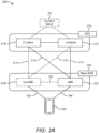
- FIG. 2B illustrates another example wireless network structure 250.
- a 5GC 260 can be viewed functionally as control plane functions, provided by an access and mobility management function (AMF) 264, and user plane functions, provided by a user plane function (UPF) 262, which operate cooperatively to form the core network (i.e., 5GC 260).
- AMF access and mobility management function
- UPF user plane function
- User plane interface 263 and control plane interface 265 connect the ng-eNB 224 to the 5GC 260 and specifically to UPF 262 and AMF 264, respectively.
- a gNB 222 may also be connected to the 5GC 260 via control plane interface 265 to AMF 264 and user plane interface 263 to UPF 262.
- ng-eNB 224 may directly communicate with gNB 222 via the backhaul connection 223, with or without gNB direct connectivity to the 5GC 260.
- the New RAN 220 may only have one or more gNBs 222, while other configurations include one or more of both ng-eNBs 224 and gNBs 222.
- Either gNB 222 or ng-eNB 224 may communicate with UEs 204 (e.g., any of the UEs depicted in FIG. 1 ).
- the base stations of the New RAN 220 communicate with the AMF 264 over the N2 interface and with the UPF 262 over the N3 interface.
- the functions of the AMF 264 include registration management, connection management, reachability management, mobility management, lawful interception, transport for session management (SM) messages between the UE 204 and a session management function (SMF) 266, transparent proxy services for routing SM messages, access authentication and access authorization, transport for short message service (SMS) messages between the UE 204 and the short message service function (SMSF) (not shown), and security anchor functionality (SEAF).
- the AMF 264 also interacts with an authentication server function (AUSF) (not shown) and the UE 204, and receives the intermediate key that was established as a result of the UE 204 authentication process.
- AUSF authentication server function
- the AMF 264 retrieves the security material from the AUSF.
- the functions of the AMF 264 also include security context management (SCM).
- SCM receives a key from the SEAF that it uses to derive access-network specific keys.
- the functionality of the AMF 264 also includes location services management for regulatory services, transport for location services messages between the UE 204 and a location management function (LMF) 270 (which acts as a location server 230), transport for location services messages between the New RAN 220 and the LMF 270, evolved packet system (EPS) bearer identifier allocation for interworking with the EPS, and UE 204 mobility event notification.
- LMF location management function
- EPS evolved packet system
- the AMF 264 also supports functionalities for non-3GPP access networks.
- Functions of the UPF 262 include acting as an anchor point for intra-/inter-RAT mobility (when applicable), acting as an external protocol data unit (PDU) session point of interconnect to a data network (not shown), providing packet routing and forwarding, packet inspection, user plane policy rule enforcement (e.g., gating, redirection, traffic steering), lawful interception (user plane collection), traffic usage reporting, quality of service (QoS) handling for the user plane (e.g., uplink/downlink rate enforcement, reflective QoS marking in the downlink), uplink traffic verification (service data flow (SDF) to QoS flow mapping), transport level packet marking in the uplink and downlink, downlink packet buffering and downlink data notification triggering, and sending and forwarding of one or more "end markers" to the source RAN node.
- the UPF 262 may also support transfer of location services messages over a user plane between the UE 204 and a location server, such as a secure user plane location (SUPL) location platform (SLP) 272.
- the functions of the SMF 266 include session management, UE Internet protocol (IP) address allocation and management, selection and control of user plane functions, configuration of traffic steering at the UPF 262 to route traffic to the proper destination, control of part of policy enforcement and QoS, and downlink data notification.
- IP Internet protocol
- the interface over which the SMF 266 communicates with the AMF 264 is referred to as the N11 interface.
- LMF 270 may be in communication with the 5GC 260 to provide location assistance for UEs 204.
- the LMF 270 can be implemented as a plurality of separate servers (e.g., physically separate servers, different software modules on a single server, different software modules spread across multiple physical servers, etc.), or alternately may each correspond to a single server.
- the LMF 270 can be configured to support one or more location services for UEs 204 that can connect to the LMF 270 via the core network, 5GC 260, and/or via the Internet (not illustrated).
- the SLP 272 may support similar functions to the LMF 270, but whereas the LMF 270 may communicate with the AMF 264, New RAN 220, and UEs 204 over a control plane (e.g., using interfaces and protocols intended to convey signaling messages and not voice or data), the SLP 272 may communicate with UEs 204 and external clients (not shown in FIG. 2B ) over a user plane (e.g., using protocols intended to carry voice and/or data like the transmission control protocol (TCP) and/or IP).
- TCP transmission control protocol
- FIGS. 3A , 3B , and 3C illustrate several exemplary components (represented by corresponding blocks) that may be incorporated into a UE 302 (which may correspond to any of the UEs described herein), a base station 304 (which may correspond to any of the base stations described herein), and a network entity 306 (which may correspond to or embody any of the network functions described herein, including the location server 230, the LMF 270, and the SLP 272) to support the file transmission operations as taught herein.
- these components may be implemented in different types of apparatuses in different implementations (e.g., in an ASIC, in a system-on-chip (SoC), etc.).
- the illustrated components may also be incorporated into other apparatuses in a communication system.
- other apparatuses in a system may include components similar to those described to provide similar functionality.
- a given apparatus may contain one or more of the components.
- an apparatus may include multiple transceiver components that enable the apparatus to operate on multiple carriers and/or communicate via different technologies.
- the UE 302 and the base station 304 each include wireless wide area network (WWAN) transceiver 310 and 350, respectively, configured to communicate via one or more wireless communication networks (not shown), such as an NR network, an LTE network, a GSM network, and/or the like.
- the WWAN transceivers 310 and 350 may be connected to one or more antennas 316 and 356, respectively, for communicating with other network nodes, such as other UEs, access points, base stations (e.g., ng-eNBs, gNBs), etc., via at least one designated RAT (e.g., NR, LTE, GSM, etc.) over a wireless communication medium of interest (e.g., some set of time/frequency resources in a particular frequency spectrum).
- a wireless communication medium of interest e.g., some set of time/frequency resources in a particular frequency spectrum.
- the WWAN transceivers 310 and 350 may be variously configured for transmitting and encoding signals 318 and 358 (e.g., messages, indications, information, and so on), respectively, and, conversely, for receiving and decoding signals 318 and 358 (e.g., messages, indications, information, pilots, and so on), respectively, in accordance with the designated RAT.
- the WWAN transceivers 310 and 350 include one or more transmitters 314 and 354, respectively, for transmitting and encoding signals 318 and 358, respectively, and one or more receivers 312 and 352, respectively, for receiving and decoding signals 318 and 358, respectively.
- the UE 302 and the base station 304 also include, at least in some cases, wireless local area network (WLAN) transceivers 320 and 360, respectively.
- WLAN transceivers 320 and 360 may be connected to one or more antennas 326 and 366, respectively, for communicating with other network nodes, such as other UEs, access points, base stations, etc., via at least one designated RAT (e.g., WiFi, LTE-D, Bluetooth ® , etc.) over a wireless communication medium of interest.
- RAT e.g., WiFi, LTE-D, Bluetooth ® , etc.
- the WLAN transceivers 320 and 360 may be variously configured for transmitting and encoding signals 328 and 368 (e.g., messages, indications, information, and so on), respectively, and, conversely, for receiving and decoding signals 328 and 368 (e.g., messages, indications, information, pilots, and so on), respectively, in accordance with the designated RAT.
- the WLAN transceivers 320 and 360 include one or more transmitters 324 and 364, respectively, for transmitting and encoding signals 328 and 368, respectively, and one or more receivers 322 and 362, respectively, for receiving and decoding signals 328 and 368, respectively.
- Transceiver circuitry including at least one transmitter and at least one receiver may comprise an integrated device (e.g., embodied as a transmitter circuit and a receiver circuit of a single communication device) in some implementations, may comprise a separate transmitter device and a separate receiver device in some implementations, or may be embodied in other ways in other implementations.
- a transmitter may include or be coupled to a plurality of antennas (e.g., antennas 316, 326, 356, 366), such as an antenna array, that permits the respective apparatus to perform transmit "beamforming," as described herein.
- a receiver may include or be coupled to a plurality of antennas (e.g., antennas 316, 326, 356, 366), such as an antenna array, that permits the respective apparatus to perform receive beamforming, as described herein.
- the transmitter and receiver may share the same plurality of antennas (e.g., antennas 316, 326, 356, 366), such that the respective apparatus can only receive or transmit at a given time, not both at the same time.
- a wireless communication device e.g., one or both of the transceivers 310 and 320 and/or 350 and 360) of the UE 302 and/or the base station 304 may also comprise a network listen module (NLM) or the like for performing various measurements.
- NLM network listen module
- the UE 302 and the base station 304 also include, at least in some cases, satellite positioning systems (SPS) receivers 330 and 370.
- the SPS receivers 330 and 370 may be connected to one or more antennas 336 and 376, respectively, for receiving SPS signals 338 and 378, respectively, such as global positioning system (GPS) signals, global navigation satellite system (GLONASS) signals, Galileo signals, Beidou signals, Indian Regional Navigation Satellite System (NAVIC), Quasi-Zenith Satellite System (QZSS), etc.
- the SPS receivers 330 and 370 may comprise any suitable hardware and/or software for receiving and processing SPS signals 338 and 378, respectively.
- the SPS receivers 330 and 370 request information and operations as appropriate from the other systems, and performs calculations necessary to determine positions of the UE 302 and the base station 304 using measurements obtained by any suitable SPS algorithm.
- the base station 304 and the network entity 306 each include at least one network interfaces 380 and 390 for communicating with other network entities.
- the network interfaces 380 and 390 e.g., one or more network access ports
- the network interfaces 380 and 390 may be implemented as transceivers configured to support wire-based or wireless signal communication. This communication may involve, for example, sending and receiving messages, parameters, and/or other types of information.
- the UE 302, the base station 304, and the network entity 306 also include other components that may be used in conjunction with the operations as disclosed herein.
- the UE 302 includes processor circuitry implementing a processing system 332 for providing functionality relating to, for example, positioning operations, and for providing other processing functionality.
- the base station 304 includes a processing system 384 for providing functionality relating to, for example, positioning operations as disclosed herein, and for providing other processing functionality.
- the network entity 306 includes a processing system 394 for providing functionality relating to, for example, positioning operations as disclosed herein, and for providing other processing functionality.
- processing systems 332, 384, and 394 may include, for example, one or more general purpose processors, multi-core processors, ASICs, digital signal processors (DSPs), field programmable gate arrays (FPGA), or other programmable logic devices or processing circuitry.
- general purpose processors multi-core processors
- ASICs application-specific integrated circuits
- DSPs digital signal processors
- FPGA field programmable gate arrays
- the UE 302, the base station 304, and the network entity 306 include memory circuitry implementing memory components 340, 386, and 396 (e.g., each including a memory device), respectively, for maintaining information (e.g., information indicative of reserved resources, thresholds, parameters, and so on).
- the UE 302, the base station 304, and the network entity 306 may include positioning components 342, 388, and 398, respectively.
- the positioning components 342, 388, and 398 may be hardware circuits that are part of or coupled to the processing systems 332, 384, and 394, respectively, that, when executed, cause the UE 302, the base station 304, and the network entity 306 to perform the functionality described herein.
- the positioning components 342, 388, and 398 may be external to the processing systems 332, 384, and 394 (e.g., part of a modem processing system, integrated with another processing system, etc.).
- the positioning components 342, 388, and 398 may be memory modules (as shown in FIGS. 3A-C ) stored in the memory components 340, 386, and 396, respectively, that, when executed by the processing systems 332, 384, and 394 (or a modem processing system, another processing system, etc.), cause the UE 302, the base station 304, and the network entity 306 to perform the functionality described herein.
- the UE 302 may include one or more sensors 344 coupled to the processing system 332 to provide movement and/or orientation information that is independent of motion data derived from signals received by the WWAN transceiver 310, the WLAN transceiver 320, and/or the SPS receiver 330.
- the sensor(s) 344 may include an accelerometer (e.g., a micro-electrical mechanical systems (MEMS) device), a gyroscope, a geomagnetic sensor (e.g., a compass), an altimeter (e.g., a barometric pressure altimeter), and/or any other type of movement detection sensor.
- MEMS micro-electrical mechanical systems
- the senor(s) 344 may include a plurality of different types of devices and combine their outputs in order to provide motion information.
- the sensor(s) 344 may use a combination of a multi-axis accelerometer and orientation sensors to provide the ability to compute positions in 2D and/or 3D coordinate systems.
- the UE 302 includes a user interface 346 for providing indications (e.g., audible and/or visual indications) to a user and/or for receiving user input (e.g., upon user actuation of a sensing device such a keypad, a touch screen, a microphone, and so on).
- a user interface 346 for providing indications (e.g., audible and/or visual indications) to a user and/or for receiving user input (e.g., upon user actuation of a sensing device such a keypad, a touch screen, a microphone, and so on).
- the base station 304 and the network entity 306 may also include user interfaces.
- IP packets from the network entity 306 may be provided to the processing system 384.
- the processing system 384 may implement functionality for an RRC layer, a packet data convergence protocol (PDCP) layer, a radio link control (RLC) layer, and a medium access control (MAC) layer.
- PDCP packet data convergence protocol
- RLC radio link control
- MAC medium access control
- the processing system 384 may provide RRC layer functionality associated with broadcasting of system information (e.g., master information block (MIB), system information blocks (SIBs)), RRC connection control (e.g., RRC connection paging, RRC connection establishment, RRC connection modification, and RRC connection release), inter-RAT mobility, and measurement configuration for UE measurement reporting; PDCP layer functionality associated with header compression/decompression, security (ciphering, deciphering, integrity protection, integrity verification), and handover support functions; RLC layer functionality associated with the transfer of upper layer packet data units (PDUs), error correction through automatic repeat request (ARQ), concatenation, segmentation, and reassembly of RLC service data units (SDUs), re-segmentation of RLC data PDUs, and reordering of RLC data PDUs; and MAC layer functionality associated with mapping between logical channels and transport channels, scheduling information reporting, error correction, priority handling, and logical channel prioritization.
- RRC connection control e.g.
- the transmitter 354 and the receiver 352 may implement Layer-1 functionality associated with various signal processing functions.
- Layer-1 which includes a physical (PHY) layer, may include error detection on the transport channels, forward error correction (FEC) coding/decoding of the transport channels, interleaving, rate matching, mapping onto physical channels, modulation/demodulation of physical channels, and MIMO antenna processing.
- FEC forward error correction
- the transmitter 354 handles mapping to signal constellations based on various modulation schemes (e.g., binary phase-shift keying (BPSK), quadrature phase-shift keying (QPSK), M-phase-shift keying (M-PSK), M-quadrature amplitude modulation (M-QAM)).
- BPSK binary phase-shift keying
- QPSK quadrature phase-shift keying
- M-PSK M-phase-shift keying
- M-QAM M-quadrature amplitude modulation
- Each stream may then be mapped to an orthogonal frequency division multiplexing (OFDM) subcarrier, multiplexed with a reference signal (e.g., pilot) in the time and/or frequency domain, and then combined together using an inverse fast Fourier transform (IFFT) to produce a physical channel carrying a time domain OFDM symbol stream.
- OFDM symbol stream is spatially precoded to produce multiple spatial streams.
- Channel estimates from a channel estimator may be used to determine the coding and modulation scheme, as well as for spatial processing.
- the channel estimate may be derived from a reference signal and/or channel condition feedback transmitted by the UE 302.
- Each spatial stream may then be provided to one or more different antennas 356.
- the transmitter 354 may modulate an RF carrier with a respective spatial stream for transmission.
- the receiver 312 receives a signal through its respective antenna(s) 316.
- the receiver 312 recovers information modulated onto an RF carrier and provides the information to the processing system 332.
- the transmitter 314 and the receiver 312 implement Layer-1 functionality associated with various signal processing functions.
- the receiver 312 may perform spatial processing on the information to recover any spatial streams destined for the UE 302. If multiple spatial streams are destined for the UE 302, they may be combined by the receiver 312 into a single OFDM symbol stream.
- the receiver 312 then converts the OFDM symbol stream from the time-domain to the frequency domain using a fast Fourier transform (FFT).
- FFT fast Fourier transform
- the frequency domain signal comprises a separate OFDM symbol stream for each subcarrier of the OFDM signal.
- the symbols on each subcarrier, and the reference signal are recovered and demodulated by determining the most likely signal constellation points transmitted by the base station 304. These soft decisions may be based on channel estimates computed by a channel estimator. The soft decisions are then decoded and de-interleaved to recover the data and control signals that were originally transmitted by the base station 304 on the physical channel. The data and control signals are then provided to the processing system 332, which implements Layer-3 and Layer-2 functionality.
- the processing system 332 provides demultiplexing between transport and logical channels, packet reassembly, deciphering, header decompression, and control signal processing to recover IP packets from the core network.
- the processing system 332 is also responsible for error detection.
- the processing system 332 provides RRC layer functionality associated with system information (e.g., MIB, SIBs) acquisition, RRC connections, and measurement reporting; PDCP layer functionality associated with header compression/decompression, and security (ciphering, deciphering, integrity protection, integrity verification); RLC layer functionality associated with the transfer of upper layer PDUs, error correction through ARQ, concatenation, segmentation, and reassembly of RLC SDUs, re-segmentation of RLC data PDUs, and reordering of RLC data PDUs; and MAC layer functionality associated with mapping between logical channels and transport channels, multiplexing of MAC SDUs onto transport blocks (TBs), demultiplexing of MAC SDUs from TBs, scheduling information reporting, error correction through hybrid automatic repeat request (HARQ), priority handling, and logical channel prioritization.
- RRC layer functionality associated with system information (e.g., MIB, SIBs) acquisition, RRC connections, and measurement reporting
- PDCP layer functionality associated
- Channel estimates derived by the channel estimator from a reference signal or feedback transmitted by the base station 304 may be used by the transmitter 314 to select the appropriate coding and modulation schemes, and to facilitate spatial processing.
- the spatial streams generated by the transmitter 314 may be provided to different antenna(s) 316.
- the transmitter 314 may modulate an RF carrier with a respective spatial stream for transmission.
- the uplink transmission is processed at the base station 304 in a manner similar to that described in connection with the receiver function at the UE 302.
- the receiver 352 receives a signal through its respective antenna(s) 356.
- the receiver 352 recovers information modulated onto an RF carrier and provides the information to the processing system 384.
- the processing system 384 provides demultiplexing between transport and logical channels, packet reassembly, deciphering, header decompression, control signal processing to recover IP packets from the UE 302. IP packets from the processing system 384 may be provided to the core network.
- the processing system 384 is also responsible for error detection.
- the UE 302, the base station 304, and/or the network entity 306 are shown in FIGS. 3A-C as including various components that may be configured according to the various examples described herein. It will be appreciated, however, that the illustrated blocks may have different functionality in different designs.
- some or all of the functionality represented by blocks 310 to 346 may be implemented by processor and memory component(s) of the UE 302 (e.g., by execution of appropriate code and/or by appropriate configuration of processor components).
- some or all of the functionality represented by blocks 350 to 388 may be implemented by processor and memory component(s) of the base station 304 (e.g., by execution of appropriate code and/or by appropriate configuration of processor components).
- some or all of the functionality represented by blocks 390 to 398 may be implemented by processor and memory component(s) of the network entity 306 (e.g., by execution of appropriate code and/or by appropriate configuration of processor components).
- FIG. 4A is a diagram 500 illustrating an example of a downlink frame structure, according to aspects of the disclosure.
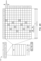
- FIG. 4B is a diagram 530 illustrating an example of channels within the downlink frame structure, according to aspects of the disclosure.
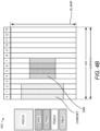
- FIG. 4C is a diagram 550 illustrating an example of an uplink frame structure, according to aspects of the disclosure.
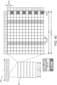
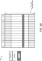
- FIG. 4D is a diagram 580 illustrating an example of channels within an uplink frame structure, according to aspects of the disclosure.
- Other wireless communications technologies may have different frame structures and/or different channels.
- LTE and in some cases NR, utilizes OFDM on the downlink and single-carrier frequency division multiplexing (SC-FDM) on the uplink.
- SC-FDM single-carrier frequency division multiplexing
- OFDM and SC-FDM partition the system bandwidth into multiple (K) orthogonal subcarriers, which are also commonly referred to as tones, bins, etc.
- K multiple orthogonal subcarriers
- Each subcarrier may be modulated with data.
- modulation symbols are sent in the frequency domain with OFDM and in the time domain with SC-FDM.
- the spacing between adjacent subcarriers may be fixed, and the total number of subcarriers (K) may be dependent on the system bandwidth.
- the spacing of the subcarriers may be 15 kHz and the minimum resource allocation (resource block) may be 12 subcarriers (or 180 kHz). Consequently, the nominal FFT size may be equal to 128, 256, 512, 1024, or 2048 for system bandwidth of 1.25, 2.5, 5, 10, or 20 megahertz (MHz), respectively.
- the system bandwidth may also be partitioned into subbands. For example, a subband may cover 1.08 MHz (i.e., 6 resource blocks), and there may be 1, 2, 4, 8, or 16 subbands for system bandwidth of 1.25, 2.5, 5, 10, or 20 MHz, respectively.
- LTE supports a single numerology (subcarrier spacing, symbol length, etc.).
- NR may support multiple numerologies ( ⁇ ), for example, subcarrier spacing of 15 kHz, 30 kHz, 60 kHz, 120 kHz, and 240 kHz or greater may be available.
- Table 1 provided below lists some various parameters for different NR numerologies. Table 1 ⁇ SCS (kHz) Symbols / Sot Slots / Subframe Slots / Frame Slot Duration (ms) Symbol Duration ( ⁇ s) Max.
- a numerology of 15 kHz is used.
- a frame e.g., 10 ms
- each subframe includes one time slot.
- time is represented horizontally (e.g., on the X axis) with time increasing from left to right
- frequency is represented vertically (e.g., on the Y axis) with frequency increasing (or decreasing) from bottom to top.
- a resource grid may be used to represent time slots, each time slot including one or more time-concurrent resource blocks (RBs) (also referred to as physical RBs (PRBs)) in the frequency domain.
- the resource grid is further divided into multiple resource elements (REs).
- An RE may correspond to one symbol length in the time domain and one subcarrier in the frequency domain.
- an RB may contain 12 consecutive subcarriers in the frequency domain and seven consecutive symbols in the time domain, for a total of 84 REs.
- an RB may contain 12 consecutive subcarriers in the frequency domain and six consecutive symbols in the time domain, for a total of 72 REs.
- the number of bits carried by each RE depends on the modulation scheme.
- the REs carry downlink reference (pilot) signals (DL-RS).
- the DL-RS may include PRS in LTE, NRS in 5G, TRS, PTRS, CRS, CSI-RS, DMRS, PSS, SSS, SSB, etc.
- FIG. 4A illustrates exemplary locations of REs carrying PRS (labeled "R").
- a collection of resource elements (REs) that are used for transmission of PRS is referred to as a "PRS resource.”
- the collection of resource elements can span multiple PRBs in the frequency domain and 'N' (e.g., 1 or more) consecutive symbol(s) within a slot in the time domain.
- a PRS resource occupies consecutive PRBs in the frequency domain.
- a comb size 'N' represents the subcarrier spacing (or frequency/tone spacing) within each symbol of a PRS resource configuration.
- a comb size 'N' represents the subcarrier spacing (or frequency/tone spacing) within each symbol of a PRS resource configuration.
- a comb size ⁇ N represents the subcarrier spacing (or frequency/tone spacing) within each symbol of a PRS resource configuration.
- a comb size ⁇ N represents the subcarrier spacing (or frequency/tone spacing) within each symbol of a PRS resource configuration.
- a comb size ⁇ N represents the subcarrier spacing (or frequency/tone spacing) within each symbol of a PRS resource configuration.
- a comb size ⁇ N represents the subcarrier spacing (or frequency/tone spacing) within each symbol of a PRS resource configuration.
- a "PRS resource set” is a set of PRS resources used for the transmission of PRS signals, where each PRS resource has a PRS resource ID.
- the PRS resources in a PRS resource set are associated with the same TRP.
- a PRS resource set is identified by a PRS resource set ID and is associated with a particular TRP (identified by a cell ID).
- the PRS resources in a PRS resource set have the same periodicity, a common muting pattern configuration, and the same repetition factor across slots.
- the repetition factor may have a length selected from ⁇ 1, 2, 4, 6, 8, 16, 32 ⁇ slots.
- a PRS resource ID in a PRS resource set is associated with a single beam (and/or beam ID) transmitted from a single TRP (where a TRP may transmit one or more beams). That is, each PRS resource of a PRS resource set may be transmitted on a different beam, and as such, a "PRS resource,” or simply “resource,” can also be referred to as a "beam.” Note that this does not have any implications on whether the TRPs and the beams on which PRS are transmitted are known to the UE.
- a “PRS instance” or “PRS occasion” is one instance of a periodically repeated time window (e.g., a group of one or more consecutive slots) where PRS are expected to be transmitted.
- a PRS occasion may also be referred to as a "PRS positioning occasion,” a “PRS positioning instance, a “positioning occasion,” “a positioning instance,” a “positioning repetition,” or simply an “occasion,” an “instance,” or a "repetition.”
- FIG. 4B illustrates an example of various channels within a downlink slot of a radio frame.
- the channel bandwidth or system bandwidth, is divided into multiple bandwidth parts (BWPs).
- a BWP is a contiguous set of PRBs selected from a contiguous subset of the common RBs for a given numerology on a given carrier.
- a maximum of four BWPs can be specified in the downlink and uplink. That is, a UE can be configured with up to four BWPs on the downlink, and up to four BWPs on the uplink. Only one BWP (uplink or downlink) may be active at a given time, meaning the UE may only receive or transmit over one BWP at a time.
- the bandwidth of each BWP should be equal to or greater than the bandwidth of the SSB, but it may or may not contain the SSB.
- a primary synchronization signal is used by a UE to determine subframe/symbol timing and a physical layer identity.
- a secondary synchronization signal is used by a UE to determine a physical layer cell identity group number and radio frame timing. Based on the physical layer identity and the physical layer cell identity group number, the UE can determine a PCI. Based on the PCI, the UE can determine the locations of the aforementioned DL-RS.
- the physical broadcast channel (PBCH), which carries an MIB, may be logically grouped with the PSS and SSS to form an SSB (also referred to as an SS/PBCH).
- the MIB provides a number of RBs in the downlink system bandwidth and a system frame number (SFN).
- the physical downlink shared channel (PDSCH) carries user data, broadcast system information not transmitted through the PBCH, such as system information blocks (SIBs), and paging messages.
- SIBs system information blocks
- the physical downlink control channel carries downlink control information (DCI) within one or more control channel elements (CCEs), each CCE including one or more RE group (REG) bundles (which may span multiple symbols in the time domain), each REG bundle including one or more REGs, each REG corresponding to 12 resource elements (one resource block) in the frequency domain and one OFDM symbol in the time domain.
- DCI downlink control information
- CCEs control channel elements
- each CCE including one or more RE group (REG) bundles (which may span multiple symbols in the time domain)
- each REG bundle including one or more REGs
- each REG corresponding to 12 resource elements (one resource block) in the frequency domain and one OFDM symbol in the time domain The set of physical resources used to carry the PDCCH/DCI is referred to in NR as the control resource set (CORESET).
- CORESET control resource set
- a PDCCH is confined to a single CORESET and is transmitted with its own DMRS. This enables UE-specific
- the CORESET spans three symbols in the time domain.
- PDCCH channels are localized to a specific region in the frequency domain (i.e., a CORESET).
- the frequency component of the PDCCH shown in FIG. 4B is illustrated as less than a single BWP in the frequency domain. Note that although the illustrated CORESET is contiguous in the frequency domain, it need not be. In addition, the CORESET may span less than three symbols in the time domain.
- the DCI within the PDCCH carries information about uplink resource allocation (persistent and non-persistent) and descriptions about downlink data transmitted to the UE.
- Multiple (e.g., up to eight) DCIs can be configured in the PDCCH, and these DCIs can have one of multiple formats. For example, there are different DCI formats for uplink scheduling, for non-MIMO downlink scheduling, for MIMO downlink scheduling, and for uplink power control.
- a PDCCH may be transported by 1, 2, 4, 8, or 16 CCEs in order to accommodate different DCI payload sizes or coding rates.
- some of the REs carry DMRS for channel estimation at the base station.
- the UE may additionally transmit SRS in, for example, the last symbol of a slot.
- the SRS may have a comb structure, and a UE may transmit SRS on one of the combs.
- the comb structure (also referred to as the "comb size") indicates the number of subcarriers in each symbol period carrying a reference signal (here, SRS). For example, a comb size of comb-4 means that every fourth subcarrier of a given symbol carries the reference signal, whereas a comb size of comb-2 means that every second subcarrier of a given symbol carries the reference signal.
- SRS reference signal
- the illustrated SRS are both comb-2.
- the SRS may be used by a base station to obtain the channel state information (CSI) for each UE.
- CSI describes how an RF signal propagates from the UE to the base station and represents the combined effect of scattering, fading, and power decay with distance.
- the system uses the SRS for resource scheduling, link adaptation, massive MIMO, beam management, etc.
- FIG. 4D illustrates an example of various channels within an uplink slot of a frame, according to aspects of the disclosure.
- a random-access channel (RACH), also referred to as a physical random-access channel (PRACH), may be within one or more slots within a frame based on the PRACH configuration.
- the PRACH may include six consecutive RB pairs within a slot.
- the PRACH allows the UE to perform initial system access and achieve uplink synchronization.
- a physical uplink control channel (PUCCH) may be located on edges of the uplink system bandwidth.
- the PUCCH carries uplink control information (UCI), such as scheduling requests, CSI reports, a channel quality indicator (CQI), a precoding matrix indicator (PMI), a rank indicator (RI), and HARQ ACK/NACK feedback.
- the physical uplink shared channel (PUSCH) carries data, and may additionally be used to carry a buffer status report (BSR), a power headroom report (PHR), and/or UCI.
- BSR buffer
- SRS resource A collection of resource elements that are used for transmission of SRS is referred to as an "SRS resource,” and may be identified by the parameter SRS-ResourceId.
- the collection of resource elements can span multiple PRBs in the frequency domain and N (e.g., one or more) consecutive symbol(s) within a slot in the time domain. In a given OFDM symbol, an SRS resource occupies consecutive PRBs.
- SRS resource set is a set of SRS resources used for the transmission of SRS signals, and is identified by an SRS resource set ID ( SRS-ResourceSetId ).
- a UE transmits SRS to enable the receiving base station (either the serving base station or a neighboring base station) to measure the channel quality between the UE and the base station.
- SRS can also be used as uplink positioning reference signals for uplink positioning procedures, such as uplink time-difference of arrival (UL-TDOA), multi-round-trip-time (multi-RTT), downlink angle-of-arrival (DL-AoA), etc.
- UL-TDOA uplink time-difference of arrival
- multi-RTT multi-round-trip-time
- DL-AoA downlink angle-of-arrival
- SRS-for-positioning also referred to as "UL-PRS”
- SRS-for-positioning also referred to as "UL-PRS”
- a new staggered pattern within an SRS resource except for single-symbol/comb-2
- a new comb type for SRS new sequences for SRS
- a higher number of SRS resource sets per component carrier a higher number of SRS resources per component carrier.
- the parameters SpatialRelationInfo and PathLossReference are to be configured based on a downlink reference signal or SSB from a neighboring TRP.
- one SRS resource may be transmitted outside the active BWP, and one SRS resource may span across multiple component carriers.
- SRS may be configured in RRC connected state and only transmitted within an active BWP. Further, there may be no frequency hopping, no repetition factor, a single antenna port, and new lengths for SRS (e.g., 8 and 12 symbols). There may also be open-loop power control and not closed-loop power control, and comb-8 (i.e., an SRS transmitted every eighth subcarrier in the same symbol) may be used. Lastly, the UE may transmit through the same transmit beam from multiple SRS resources for UL-AoA. All of these are features that are additional to the current SRS framework, which is configured through RRC higher layer signaling (and potentially triggered or activated through MAC control element (CE) or DCI).
- CE MAC control element
- positioning reference signal and “PRS” may sometimes refer to specific reference signals that are used for positioning in LTE systems.
- the terms “positioning reference signal” and “PRS” refer to any type of reference signal that can be used for positioning, such as but not limited to, PRS in LTE, NRS in 5G, TRS, PTRS, CRS, CSI-RS, DMRS, PSS, SSS, SSB, SRS, UL-PRS, etc.
- positioning reference signal and “PRS” refer to downlink or uplink positioning reference signals, unless otherwise indicated.
- a UE-centric RTT estimation is similar to the network-based method, except that the UE transmits uplink RTT measurement signal(s) (e.g., when instructed by a serving base station or location server), which are received by multiple base stations in the neighborhood of the UE. Each involved base station responds with a downlink RTT response message, which may include the arrival time of the RTT measurement signal at the base station in the RTT response message payload.
- uplink RTT measurement signal(s) e.g., when instructed by a serving base station or location server
- Each involved base station responds with a downlink RTT response message, which may include the arrival time of the RTT measurement signal at the base station in the RTT response message payload.
- FIG. 5 illustrates an exemplary wireless communications system 500 according to aspects of the disclosure.
- a UE 504 (which may correspond to any of the UEs described herein) is attempting to calculate an estimate of its location, or assist another positioning entity (e.g., a base station or core network component, another UE, a location server, a third party application, etc.) to calculate an estimate of its location.
- the UE 504 may communicate wirelessly with a plurality of base stations (BS) 502-1, 502-2, and 502-3 (collectively, base stations 502, and which may correspond to any of the base stations described herein) using RF signals and standardized protocols for the modulation of the RF signals and the exchange of information packets.
- BS base stations
- the UE 504 may determine its location, or assist in the determination of its location, in a predefined reference coordinate system.
- the UE 504 may specify its location using a two-dimensional coordinate system; however, the aspects disclosed herein are not so limited, and may also be applicable to determining locations using a three-dimensional coordinate system, if the extra dimension is desired.
- FIG. 5 illustrates one UE 504 and three base stations 502, as will be appreciated, there may be more UEs 504 and more base stations 502.
- the base stations 502 may be configured to broadcast reference RF signals (e.g., PRS, NRS, CRS, TRS, CSI-RS, SSB, PSS, SSS, etc.) to UEs 504 in their coverage area to enable a UE 504 to measure characteristics of such reference signals.
- reference RF signals e.g., PRS, NRS, CRS, TRS, CSI-RS, SSB, PSS, SSS, etc.
- the UE 504 may measure the time of arrival (ToA) of specific reference signals (e.g., PRS, NRS, CRS, CSI-RS, etc.) transmitted by at least three different base stations 502-1, 502-2, and 502-3 and may use the RTT positioning method to report these ToAs (and additional information) back to the serving base station 502 or another positioning entity (e.g., location server 230, LMF 270, SLP 272).
- ToA time of arrival
- specific reference signals e.g., PRS, NRS, CRS, CSI-RS, etc.
- the UE 504 may measure reference signals from one of multiple cells or TRPs supported by a base station 502. Where the UE 504 measures reference signals transmitted by a cell/TRP supported by a base station 502, the at least two other reference signals measured by the UE 504 to perform the RTT procedure would be from cells/TRPs supported by base stations 502 different from the first base station 502 and may have good or poor signal strength at the UE 504.
- the locations of the involved base stations 502 may be provided to the serving base station 502 or the UE 504 by a location server with knowledge of the network geometry (e.g., location server 230, LMF 270, SLP 272).
- the location server may determine the location of the UE 504 using the known network geometry.
- RTT techniques can measure the time between sending an RTT measurement signal and receiving an RTT response signal. These methods may utilize calibration to remove any processing delays. In some environments, it may be assumed that the processing delays for the UE 504 and the base stations 502 are the same. However, such an assumption may not be true in practice.
- a location estimate (e.g., for a UE 504) may be referred to by other names, such as a position estimate, location, position, position fix, fix, or the like.
- a position estimate may be geodetic and comprise coordinates (e.g., latitude, longitude, and possibly altitude) or may be civic and comprise a street address, postal address, or some other verbal description of a location.
- a position estimate may further be defined relative to some other known location or defined in absolute terms (e.g., using latitude, longitude, and possibly altitude).
- a position estimate may include an expected error or uncertainty (e.g., by including an area or volume within which the location is expected to be included with some specified or default level of confidence).
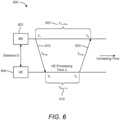
- FIG. 6 is an exemplary diagram 600 showing exemplary timings of RTT measurement signals exchanged between a base station 602 (e.g., any of the base stations described herein) and a UE 604 (e.g., any of the UEs described herein), according to aspects of the disclosure.
- the base station 602 sends an RTT measurement signal 610 (e.g., PRS, NRS, CRS, CSI-RS, etc.) to the UE 604 at time T 1 .
- the RTT measurement signal 610 has some propagation delay T Prop as it travels from the base station 602 to the UE 604.
- the UE 604 receives/measures the RTT measurement signal 610.
- the UE 604 transmits an RTT response signal 620 (e.g., an SRS, UL-PRS, DMRS, etc.) at time T 3 .
- the base station 602 receives/measures the RTT response signal 620 from the UE 604 at time T 4 (the ToA of the RTT response signal 620 at the base station 602).
- the receiver In order to identify the ToA (e.g., T 2 ) of an RF signal (e.g., an RTT measurement signal 610) transmitted by a given network node, the receiver (e.g., UE 604) first jointly processes all the resource elements (REs) on the channel on which the transmitter (e.g., base station 602) is transmitting the RF signal, and performs an inverse Fourier transform to convert the received RF signals to the time domain.
- the conversion of the received RF signals to the time domain is referred to as estimation of the channel energy response (CER).
- the CER shows the peaks on the channel over time, and the earliest "significant" peak should therefore correspond to the ToA of the RF signal.
- the receiver will use a noise-related quality threshold to filter out spurious local peaks, thereby presumably correctly identifying significant peaks on the channel.
- the UE 604 may choose a ToA estimate that is the earliest local maximum of the CER that is at least X decibels (dB) higher than the median of the CER and a maximum Y dB lower than the main peak on the channel.
- the receiver determines the CER for each RF signal from each transmitter in order to determine the ToA of each RF signal from the different transmitters.
- the RTT response signal 620 may explicitly include the difference between time T 3 and time T 2 (i.e., T Rx ⁇ Tx 612), referred to as the "UE Rx-Tx" measurement. Alternatively, it may be derived from the timing advance (TA), i.e., the relative UL/DL frame timing and specification location of uplink reference signals.
- TA timing advance
- the UE 604 can perform an RTT procedure with multiple base stations 602, referred to as “multi-RTT” or “multi-cell RTT.” Such an RTT procedure does not require synchronization between the involved base stations 602.
- the UE 604 and the involved base stations 602 report their respective measurements to a positioning entity (e.g., the UE 604, a serving base station 602, a location server, such as location server 230, LMF 270, SLP 272), which calculates an estimate of the location of the UE 604 based on the measurements.
- a positioning entity e.g., the UE 604, a serving base station 602, a location server, such as location server 230, LMF 270, SLP 272
- the TA is a MAC control element (MAC-CE) or random-access response (RAR) that is used to control uplink signal transmission timing.
- a base station e.g., base station 602 periodically measures the time difference between reception of the PUSCH (see e.g., FIG. 4D ), PUCCH (see e.g., FIG. 4D ), and/or SRS (see e.g., FIG. 4C ) from a UE (e.g., UE 604) and the base station's own frame timing. If needed, the base station can send a TA command to the UE instructing it to change the PUSCH/PUCCH/SRS transmission time to better align with the base station's frame timing.
- the base station can send a TA command to the UE instructing it to send the PUSCH/PUCCH/SRS some period of time later than it is currently sending it.
- the base station can send a TA command to the UE instructing it to send the PUSCH/PUCCH/SRS some period of time earlier than it is currently sending it.
- N TA N TA _ old + T A ⁇ 31 ⁇ 16 ⁇ 64 2 ⁇
- N TA the new TA value
- N TA_old the previous TA value
- T A is an index value (from 0 to 63) from the MAC-CE
- ⁇ indicates the subcarrier numerology (see Table 1).
- N TA T A ⁇ 16 ⁇ 64 2 ⁇
- N TA the new TA value
- T A an index value (from 0 to 3846) from the RAR
- ⁇ indicates the subcarrier numerology (e.g., from 0 to 3).
- N TA + N TAoffset T c N TAoffset T c
- N TA is the new TA value as calculated in Equation 1 or Equation 2
- N TAoffset depends on the frequency range and band of the cell used for uplink transmission (as shown in Table 2 below)
- T c 0.509 nanoseconds (ns).
- Table 2 Frequency Range and Band of the Cell Used for Uplink Transmission N TAoffset (Unit: T c ) FR1 frequency division duplex (FDD) band without LTE-NR coexistence OR FR1 time division duplex (TDD) band without LTE-NR coexistence 25600 FR1 FDD band with LTE-NR coexistence 0 FR1 TDD band with LTE-NR coexistence 39936 or 25600 FR2 13792
- N T,1 is a time duration of N 1 symbols corresponding to a PDSCH reception time for PDSCH processing capability 1 when an additional PDSCH DMRS is configured
- N T,2 is a time duration of N 2 symbols corresponding to a PUSCH preparation time for PUSCH processing capability 1
- N TAmax is the maximum TA value that can be provided by the TA command field
- N slot subframe ⁇ is a number of slots per subframe
- T sf is the subframe duration of 1 ms.
- a TA command may have the following granularity (i.e., the step size of the delay or advance): 521 ns for 15 kHz subcarrier spacing, 260 ns for 30 kHz subcarrier spacing, 130 ns for 60 kHz subcarrier spacing, and 65 ns for 120 kHz subcarrier spacing. That is, for 15 kHz subcarrier spacing, the delay specified by a TA command would be a delay of some multiple (e.g., 1, 2, 3, etc.) of 521 ns.
- a UE may be configured to receive multiple reference signals (e.g., PRS) from one base station inside a particular radio frame.
- the UE may further be configured to transmit multiple SRS (which may be part of the same or different component carriers or bands) inside the same frame (e.g., as part of an RTT procedure).
- a base station may transmit multiple PRS as the RTT measurement signal (e.g., RTT measurement signal 610) and the UE may respond with multiple SRS as the RTT response signal (e.g., RTT response signal 620).
- the UE averages the CER of all of the PRS to determine the time of arrival (e.g., T 2 in FIG. 6 ) of the RTT measurement signal.
- the base station averages the CER of all of the SRS to determine the time of arrival (e.g., T 4 in FIG. 6 ) of the RTT response signal.
- This averaging of multiple reference signals improves the accuracy of the time of arrival estimates, and thereby, the location estimate.
- the UE receives a MAC-CE command that changes the TA between the SRS transmissions in a radio frame, it can result in degraded positioning performance.
- FIG. 7 is a diagram 700 of an exemplary scenario in which a positioning session is interrupted by a TA command.
- a base station (labeled “gNB1”) transmits multiple PRS (labeled "PRS1") during a radio frame 710, and a UE receives those PRS from the base station during a corresponding radio frame 720.
- the base station transmits "PRS1" in a first slot 702 (labeled "Slot X") and a second slot 704 (labeled "Slot X+N”) of radio frame 710, and the UE receives the "PRS1" in a first slot 722 and a second slot 726, respectively, of a radio frame 720.
- the UE Because the UE receives "PRS1" as part of a positioning session, the UE transmits an SRS (labeled "SRS1") in a subsequent slot. Thus, in the example of FIG. 7 , the UE transmits "SRS1" 724 after receiving "PRS1" in slot 722 and "SRS1" 728 after receiving "PRS1" in slot 726.
- SRS1 SRS
- the UE receives a TA command in a MAC-CE 730 after receiving the "PRS1" in slot 726 and before sending the "SRS1" 728.
- the times of arrival of the "SRS1" 724 and 728 relative to the base station's frame time will be different from each other by at least the amount of the new TA derived from the MAC-CE 730.
- the difference in the times of arrival is not based on a difference in location between the UE and the base station, propagation characteristics of the SRS, or any other relevant factor, but rather, simply the new TA.
- the TA command is to add an additional delay to the transmission of uplink signals (e.g., "SRS1")
- SRS1 uplink signals
- SRS1 SRS transmitted after the TA command is applied
- CERs times of arrival, or CERs
- the decrease in positioning accuracy can be quite significant.
- the propagation time between the UE and the base station could appear to be 521 ns longer or shorter than it actually is.
- the UE can report as the UE Rx-Tx measurement (e.g., T Rx ⁇ Tx 612) if a TA command is received during a positioning session.
- the specified/requested positioning accuracy for the positioning session is not guaranteed to be met if a TA command is received during a positioning session.
- the UE may timestamp each UE Rx-Tx measurement at the slot level with respect to the reference cell (or serving cell).
- the timestamp of each UE Rx-Tx measurement may be such that the UE reports the following tuple of information: ⁇ slot ID in which PRS is received, slot ID in which SRS is transmitted ⁇ .
- the reported UE Rx-Tx measurement may refer to the latest or earliest measurement inside the reported frame.
- the UE may not apply the TA command to SRS used only for positioning, but may instead apply it for the remaining uplink channels. In this case, there would likely need to be gaps between the SRS-for-positioning and the uplink channels in the adjacent OFDM symbols. However, it is possible that the gaps may not be needed if the TA is small enough (e.g., within the size of the CP) to perform via a phase-ramp in the frequency domain (circular shift). Alternatively, the gaps may not be needed if the TA can be covered by the existing downlink-to-uplink switch gap (at the end of the slot for SRS). This may hold only for certain values of the TA command, and the gap configuration could be a function of the TA command. If the SRS is used for both positioning and communications, then the UE may be expected to apply the TA command as specified by the serving cell.
- All of these options enable the base station or other positioning entity (e.g., location server 230, LMF 270, SLP 272) to exclude CERs of the SRS received after the TA command is applied from being averaged with the CERs of SRS received before the TA command is applied. While this may improve positioning performance over calculating an average of all SRS, there may not be very many SRS transmitted in a positioning session, and therefore, the base station not being able to average the CERs of all SRS can still result in poor positioning performance.
- location server 230 e.g., location server 230, LMF 270, SLP 272
- the UE adds a timestamp with a larger granularity of the time period during which the SRS transmission is valid, it would mean that the receiving base station (especially neighboring base stations) (1) would not be able to average the received SRS across different slots, since it would not know how much the CER of the new SRS is shifted in time, and (2) would only be able to perform one-shot measurements and then forward them to the positioning entity.
- the present disclosure proposes signaling aspects to ensure that both serving and neighboring base stations are able to compensate for different uplink timings of SRS, average the CERs of the SRS, and then derive the subsequent positioning measurements, such as the received time of arrival (RTOA) (e.g., T 4 in FIG. 6 ) or the BS Tx-Rx measurement (e.g., T Tx ⁇ Rx 622 in FIG. 6 ).
- RTOA received time of arrival
- the present disclosure provides techniques for the UE to report the applied SRS adjustment(s) within a measurement window.
- the UE can include a report in an uplink channel (e.g., PUSCH or PUCCH) indicating the timing adjustment of the corresponding SRS in the measurement window.
- an uplink channel e.g., PUSCH or PUCCH
- this information may be received by the serving base station and then distributed to the neighboring base stations through the Xn interface. In that way, all of the involved base stations can adjust their SRS reception times and average the adjusted SRS CERs to obtain the RTOA or the BS Tx-Rx measurements.
- this information may be received by the positioning entity (e.g., the serving base station, a location server), and the positioning entity can distribute it to the involved base stations, which can use the information to adjust the SRS reception timing. Then, the base stations can forward the RTOAs of the SRS to the positioning entity.
- the positioning entity e.g., the serving base station, a location server
- the positioning entity can distribute it to the involved base stations, which can use the information to adjust the SRS reception timing. Then, the base stations can forward the RTOAs of the SRS to the positioning entity.
- the measurement window can correspond to a positioning session, a radio frame, a collection of frames, a subframe, a collection of subframes, a slot, a collection of slots, a collection of consecutive SRS transmissions from the UE (e.g., 10 SRS transmissions), or the like.
- the UE can be configured with this measurement window through higher layer signaling (e.g., LTE positioning protocol (LPP), RRC). If no timing adjustment to the SRS transmissions is performed inside the measurement window, the UE can report "0" as the needed adjustment, or may not report any number.
- LTP LTE positioning protocol
- RRC Radio Resource Control
- the timing adjustment of SRS transmissions need only be reported if the requested positioning accuracy is larger than a specified (threshold) value.
- the threshold value could be dependent on the system numerology (see Table 1). Alternatively, or additionally, the threshold value could be dependent on the granularity of the reporting of the UE Rx-Tx measurement. For example, if the UE Rx-Tx measurement is reported with a granularity of ⁇ X' ns, then, if the SRS is adjusted with a TA that results in a change of much less than 'X' ns, there would be no need to report the SRS timing adjustment.
- the reporting of the timing adjustment could be discretized to match the corresponding TA command.
- the reported timing adjustment to SRS transmissions would match the value of the corresponding TA command.
- the report may include 'Z' bits to cover the cases ⁇ 2 Z 2 , ... , 2 Z 2 ⁇ 1 .
- each 'Z' bits can indicate that the current SRS transmission has been adjusted with respect to the previous SRS transmission.
- each 'Z' bits can indicate that the SRS transmission has been adjusted with respect to the first SRS transmission in the measurement window.
- the timing adjustment may be reported with a single bit.
- the report for a measurement window may include one bit per SRS transmission (or slot / subframe / frame ID) inside the measurement window. As a first option, this bit can indicate that the ⁇ Xth' SRS has been adjusted with respect to the previous SRS. For example, given 10 SRS transmissions in the measurement window and a TA command applied after the sixth SRS transmission, the report may include six '0' bits for the first six SRS transmissions, followed by one '1' bit for the first SRS transmission transmitted after the new TA is applied, followed by three '0' bits indicating no further TA change from the previous (seventh) SRS transmission.
- this bit can indicate that the ⁇ Xth' SRS has been adjusted with respect to the first SRS in the measurement window. For example, given 10 SRS transmissions in the measurement window and a TA command applied after the sixth SRS transmission, the report may include six '0' bits for the first six SRS transmissions, followed by four '1' bits for the remaining SRS transmissions.
- the report may include one bit for all of the SRS transmissions in the measurement window, indicating whether or not at least one SRS in the measurement window was adjusted. For example, given 10 SRS transmissions in the measurement window and a TA command applied after the sixth SRS transmission, the report may be a single bit set to '1.' In this way, a report indicating that a second timing adjustment parameter has been applied to a second SRS indicates that the second timing adjustment associated with the second SRS is different than a first timing adjustment associated with a first SRS.
- the UE could report a set of SRS indexes indicating when the reported SRS transmission timing changed.
- the likelihood that the UE receives more than some number 'X' (e.g., 1, 2, 3, etc.) TA commands during a measurement window is small.
- the UE would only need to report up to 'X' SRS index values (or slot / subframe / frame indexes) corresponding to the first SRS transmitted after the timing adjustment is applied. For example, given 10 SRS transmissions in the measurement window and a TA command applied after the third and sixth SRS transmissions, the report may include the index values for the fourth and seventh SRS transmissions (i.e., the first SRS transmissions after the TA commands were received).
- the base station may assume that up to a specific timing adjustment was applied.
- the maximum timing adjustment may be one TA step (e.g., 521 ns for 15 KHz subcarrier spacing) or 'Z' (e.g., 2, 3, etc.) TA steps. 'Z' may also be reported by the UE separately or in the same report.
- the serving base station may forward the TA commands to the neighboring base stations.
- the UE may not apply the TA command for some number of subsequent SRS transmissions since it may miss the TA command or because it has simply not applied it yet.
- the neighboring base stations can perform some implementation-based solutions, such as a blind check of whether or not the TA command was applied, to attempt to average the SRS measurements correctly.
- the UE may still report information on whether/which SRS transmissions are affected, as described above. Together with the TA information received from the serving base station, the neighboring base station(s) may combine these two different information sources to obtain the exact timing of the SRS transmissions.
- the SRS transmission timing can be adjusted due to the reception of an explicit TA command, as described in the foregoing, or due to autonomous UE correction based on the UE sensing a change in the downlink timing.
- the reporting solutions described above apply in both cases. The same solution can be used because, although the TA command is known to the base station that issues it, there is no precise action-time specified for when the UE will apply it. In addition, the UE may spread out the application of the TA over several slots, so it may be hard for the base station to detect.
- FIG. 8 illustrates an exemplary method 800 of wireless communication, according to aspects of the disclosure.
- the method 800 may be performed by any of the UEs described herein.
- the UE transmits, at a first time during a measurement window for positioning purposes, a first uplink reference signal in accordance with a first timing adjustment parameter, wherein the first time is offset from a downlink frame time (e.g., the start of reception of a downlink radio frame) of a base station (e.g., any of the base stations described herein) by an amount of the first timing adjustment parameter.
- operation 810 may be performed by WWAN transceiver 310, processing system 332, memory component 340, and/or positioning component 342, any or all of which may be considered means for performing this operation.
- operation 820 determines whether to use a second timing adjustment parameter.
- operation 820 may be performed by WWAN transceiver 310, processing system 332, memory component 340, and/or positioning component 342, any or all of which may be considered means for performing this operation.
- the UE transmits, in response to the determination to use the second timing adjustment parameter, at a second time during the measurement window, a second uplink reference signal in accordance with a second timing adjustment parameter, wherein the second time is offset from the downlink frame time of the base station by an amount of the second timing adjustment parameter.
- operation 830 may be performed by WWAN transceiver 310, processing system 332, memory component 340, and/or positioning component 342, any or all of which may be considered means for performing this operation.
- the UE transmits a report indicating that the second timing adjustment parameter has been applied to at least the second uplink reference signal.
- the report may indicate that there have been no changes.
- operation 840 may be performed by WWAN transceiver 310, processing system 332, memory component 340, and/or positioning component 342, any or all of which may be considered means for performing this operation.
- FIG. 9 illustrates an exemplary method 900 of wireless communication, according to aspects of the disclosure.
- the method 900 may be performed by any of the base stations described herein.
- the base station receives, from a UE (e.g., any of the UEs described herein) during a measurement window for positioning purposes, a first uplink reference signal.
- operation 910 may be performed by WWAN transceiver 350, processing system 384, memory component 386, and/or positioning component 388, any or all of which may be considered means for performing this operation.
- the base station receives, from the UE during the measurement window, a second uplink reference signal.
- operation 920 may be performed by WWAN transceiver 350, processing system 384, memory component 386, and/or positioning component 388, any or all of which may be considered means for performing this operation.
- the base station receives a report indicating that a timing adjustment parameter has been adjusted for at least the second uplink reference signal.
- operation 930 may be performed by WWAN transceiver 350, processing system 384, memory component 386, and/or positioning component 388, any or all of which may be considered means for performing this operation.
- the base station determines one or more positioning measurements based on the first uplink reference signal, the second uplink reference signal, and information in the report related to the second uplink reference signal.
- operation 940 may be performed by WWAN transceiver 350, processing system 384, memory component 386, and/or positioning component 388, any or all of which may be considered means for performing this operation.
- a general purpose processor may be a microprocessor, but in the alternative, the processor may be any conventional processor, controller, microcontroller, or state machine.
- a processor may also be implemented as a combination of computing devices, e.g., a combination of a DSP and a microprocessor, a plurality of microprocessors, one or more microprocessors in conjunction with a DSP core, or any other such configuration.
- a software module may reside in random access memory (RAM), flash memory, read-only memory (ROM), erasable programmable ROM (EPROM), electrically erasable programmable ROM (EEPROM), registers, hard disk, a removable disk, a CD-ROM, or any other form of storage medium known in the art.
- An exemplary storage medium is coupled to the processor such that the processor can read information from, and write information to, the storage medium.
- the storage medium may be integral to the processor.
- the processor and the storage medium may reside in an ASIC.
- the ASIC may reside in a user terminal (e.g., UE).
- the processor and the storage medium may reside as discrete components in a user terminal.
- the functions described may be implemented in hardware, software, firmware, or any combination thereof. If implemented in software, the functions may be stored on or transmitted over as one or more instructions or code on a computer-readable medium.
- Computer-readable media includes both computer storage media and communication media including any medium that facilitates transfer of a computer program from one place to another.
- a storage media may be any available media that can be accessed by a computer.
- such computer-readable media can comprise RAM, ROM, EEPROM, CD-ROM or other optical disk storage, magnetic disk storage or other magnetic storage devices, or any other medium that can be used to carry or store desired program code in the form of instructions or data structures and that can be accessed by a computer.
- any connection is properly termed a computer-readable medium.
- the software is transmitted from a website, server, or other remote source using a coaxial cable, fiber optic cable, twisted pair, digital subscriber line (DSL), or wireless technologies such as infrared, radio, and microwave
- the coaxial cable, fiber optic cable, twisted pair, DSL, or wireless technologies such as infrared, radio, and microwave are included in the definition of medium.
- Disk and disc includes compact disc (CD), laser disc, optical disc, digital versatile disc (DVD), floppy disk and Blu-ray disc where disks usually reproduce data magnetically, while discs reproduce data optically with lasers. Combinations of the above should also be included within the scope of computer-readable media.
Landscapes
- Engineering & Computer Science (AREA)
- Computer Networks & Wireless Communication (AREA)
- Signal Processing (AREA)
- Radar, Positioning & Navigation (AREA)
- Remote Sensing (AREA)
- Physics & Mathematics (AREA)
- General Physics & Mathematics (AREA)
- Mobile Radio Communication Systems (AREA)
Claims (15)
- Benutzergerät, UE, (104, 302), umfassend:einen Speicher;mindestens einen Sendeempfänger; undmindestens einen Prozessor, der kommunikativ mit dem Speicher und dem mindestens einen Sendeempfänger gekoppelt ist, wobei der mindestens eine Prozessor konfiguriert ist zum:
Bewirken, dass der mindestens eine Sendeempfänger zu einem ersten Zeitpunkt während eines Messfensters zu Positionierungszwecken ein erstes Uplink-Referenzsignal gemäß einem ersten Zeiteinstellungsparameter überträgt, wobei der erste Zeitpunkt von einer Downlink-Rahmenzeit einer Basisstation (102, 304) um einen Betrag des ersten Zeiteinstellungsparameters versetzt ist; und dadurch gekennzeichnet, dass der Prozessor ferner konfiguriert ist zumBewirken, dass der mindestens eine Sendeempfänger einen Bericht überträgt, der anzeigt, dass der erste Zeiteinstellungsparameter auf mindestens das erste Uplink-Referenzsignal angewendet wurde. - UE nach Anspruch 1, wobei:
der mindestens eine Prozessor ferner konfiguriert ist zum:Bestimmen, ob ein zweiter Zeiteinstellungsparameter verwendet werden soll;als Reaktion auf die Bestimmung, den zweiten Zeiteinstellungsparameter zu verwenden, Bewirken, dass der mindestens eine Sendeempfänger zu einem zweiten Zeitpunkt während des Messfensters ein zweites Uplink-Referenzsignal gemäß dem zweiten Zeiteinstellungsparameter überträgt, wobei der zweite Zeitpunkt von der Downlink-Rahmenzeit der Basisstation um einen Betrag des zweiten Zeiteinstellungsparameters versetzt ist; undBewirken, dass der mindestens eine Sendeempfänger einen Bericht überträgt, der anzeigt, dass der zweite Zeiteinstellungsparameter auf mindestens das zweite Uplink-Referenzsignal angewendet wurde. - UE nach Anspruch 1, wobei:der mindestens eine Prozessor, der zum Bestimmen konfiguriert ist, umfasst, dass der mindestens eine Prozessor konfiguriert ist, um während des Messfensters über den mindestens einen Sendeempfänger einen Zeiteinstellungsbefehl zu empfangen, der den zweiten Zeiteinstellungsparameter beinhaltet, undder mindestens eine Prozessor konfiguriert ist, um zu bewirken, dass der mindestens eine Sendeempfänger das zweite Uplink-Referenzsignal gemäß dem zweiten Zeiteinstellungsparameter als Reaktion auf den Empfang des Zeiteinstellungsbefehls überträgt.
- UE nach Anspruch 1, wobei der Bericht die Menge des zweiten Zeiteinstellungsparameters beinhaltet.
- UE nach Anspruch 4, wobei der Bericht mit einem Wert eines TA-Befehls übereinstimmt.
- UE nach Anspruch 1, wobei das erste Uplink-Referenzsignal und das zweite Uplink-Referenzsignal auf unterschiedlichen Komponententrägern und/oder unterschiedlichen Bändern übertragen werden.
- UE nach Anspruch 1, wobei der Bericht ein Bit pro Uplink-Referenzsignal beinhaltet, das während des Messfensters übertragen wird, um anzuzeigen, welche Uplink-Referenzsignale, die während des Messfensters übertragen werden, Übertragungszeiten aufweisen, die geändert wurden, und
wobei jedes Bit des Berichts anzeigt, ob eine Übertragungszeit eines Uplink-Referenzsignals, das während des Messfensters übertragen wird, bis zu einem Schwellenwert von einer Übertragungszeit eines vorhergehenden Uplink-Referenzsignals, das während des Messfensters übertragen wird, geändert wurde oder nicht. - UE nach Anspruch 1, wobei der Bericht ein Bit umfasst, das anzeigt, ob eine Übertragungszeit eines beliebigen Uplink-Referenzsignals, das während des Messfensters übertragen wird, bis zu einem Schwellenwert von einer Übertragungszeit eines zuerst auftretenden Uplink-Referenzsignals, das während des Messfensters übertragen wird, geändert wurde oder nicht.
- UE nach Anspruch 1, wobei der Bericht einen oder mehrere Indexwerte umfasst, die identifizieren, welche Uplink-Referenzsignale, die während des Messfensters übertragen werden, eine Übertragungszeit aufweisen, die sich von vorherigen Uplink-Referenzsignalen unterscheidet, die während des Messfensters übertragen werden.
- Basisstation (102, 304), umfassend:einen Speicher;mindestens einen Sendeempfänger; undmindestens einen Prozessor, der kommunikativ mit dem Speicher und dem mindestens einen Sendeempfänger gekoppelt ist, wobei der mindestens eine Prozessor konfiguriert ist zum:Empfangen, von einem Benutzergerät, UE, (104, 302) während eines Messfensters für Positionierungszwecke, eines ersten Uplink-Referenzsignals;Empfangen, von dem UE während des Messfensters, eines zweiten Uplink-Referenzsignals; wobei die Basisstation dadurch gekennzeichnet ist, dass der Prozessor ferner konfiguriert ist zumEmpfangen, über den mindestens einen Sendeempfänger, eines Berichts, der anzeigt, dass ein Zeiteinstellungsparameter für mindestens das zweite Uplink-Referenzsignal eingestellt wurde; undBestimmen einer oder mehrerer Positionierungsmessungen basierend auf dem ersten Uplink-Referenzsignal, dem zweiten Uplink-Referenzsignal und Informationen in dem Bericht in Bezug auf das zweite Uplink-Referenzsignal.
- Basisstation nach Anspruch 10, wobei der mindestens eine Prozessor, der zum Bestimmen konfiguriert ist, umfasst, dass der mindestens eine Prozessor konfiguriert ist, um die eine oder die mehreren Positionierungsmessungen durch gemeinsames Verarbeiten des ersten Uplink-Referenzsignals und des zweiten Uplink-Referenzsignals basierend auf den Informationen in dem Bericht in Bezug auf das zweite Uplink-Referenzsignal zu bestimmen.
- Verfahren zur drahtlosen Kommunikation, das von einem Benutzergerät, UE, (104, 302) durchgeführt wird, umfassend:
Übertragen, zu einem ersten Zeitpunkt während eines Messfensters zu Positionierungszwecken, eines ersten Uplink-Referenzsignals gemäß einem ersten Zeiteinstellungsparameter, wobei der erste Zeitpunkt von einer Downlink-Rahmenzeit einer Basisstation (102, 304) um einen Betrag des ersten Zeiteinstellungsparameters versetzt ist; und
Übertragen eines Berichts, der anzeigt, dass der erste Zeiteinstellungsparameter auf mindestens das erste Uplink-Referenzsignal angewendet wurde. - Verfahren nach Anspruch 12, ferner umfassend:Bestimmen, ob ein zweiter Zeiteinstellungsparameter verwendet werden soll;als Reaktion auf die Bestimmung, den zweiten Zeiteinstellungsparameter zu verwenden, Übertragen, zu einem zweiten Zeitpunkt während des Messfensters, eines zweiten Uplink-Referenzsignals gemäß dem zweiten Zeiteinstellungsparameter, wobei der zweite Zeitpunkt von der Downlink-Rahmenzeit der Basisstation um einen Betrag des zweiten Zeiteinstellungsparameters versetzt ist; undÜbertragen eines Berichts, der anzeigt, dass der zweite Zeiteinstellungsparameter auf mindestens das zweite Uplink-Referenzsignal angewendet wurde.
- Verfahren zur drahtlosen Kommunikation, das von einer Basisstation (102, 304) durchgeführt wird, umfassend:Empfangen, von einem Benutzergerät, UE, (104, 302) während eines Messfensters für Positionierungszwecke, eines ersten Uplink-Referenzsignals;Empfangen, von dem UE während des Messfensters, eines zweiten Uplink-Referenzsignals;Empfangen eines Berichts, der anzeigt, dass ein Zeiteinstellungsparameter für mindestens das zweite Uplink-Referenzsignal eingestellt wurde; undBestimmen einer oder mehrerer Positionierungsmessungen basierend auf dem ersten Uplink-Referenzsignal, dem zweiten Uplink-Referenzsignal und Informationen in dem Bericht in Bezug auf das zweite Uplink-Referenzsignal.
- Computerprogramm, umfassend Anweisungen, die, wenn das Programm von einem Prozessor eines Benutzergeräts, UE, ausgeführt wird, den Prozessor veranlassen, das Verfahren nach einem der Ansprüche 12 bis 13 auszuführen, oder wenn es von einem Prozessor einer Basisstation ausgeführt wird, den Prozessor veranlassen, das Verfahren nach Anspruch 14 auszuführen.
Applications Claiming Priority (3)
| Application Number | Priority Date | Filing Date | Title |
|---|---|---|---|
| GR20190100223 | 2019-05-21 | ||
| US16/872,599 US11751082B2 (en) | 2019-05-21 | 2020-05-12 | Reporting of information related to sounding reference signals (SRS) timing adjustments |
| PCT/US2020/032605 WO2020236473A1 (en) | 2019-05-21 | 2020-05-13 | Reporting of information related to sounding reference signals (srs) timing adjustments |
Publications (2)
| Publication Number | Publication Date |
|---|---|
| EP3973322A1 EP3973322A1 (de) | 2022-03-30 |
| EP3973322B1 true EP3973322B1 (de) | 2024-09-18 |
Family
ID=73456578
Family Applications (1)
| Application Number | Title | Priority Date | Filing Date |
|---|---|---|---|
| EP20730799.2A Active EP3973322B1 (de) | 2019-05-21 | 2020-05-13 | Berichten von informationen in zusammenhang mit zeitanpassungen von sounding-referenzsignalen (srs) |
Country Status (4)
| Country | Link |
|---|---|
| US (2) | US11751082B2 (de) |
| EP (1) | EP3973322B1 (de) |
| CN (2) | CN118890651A (de) |
| WO (1) | WO2020236473A1 (de) |
Families Citing this family (19)
| Publication number | Priority date | Publication date | Assignee | Title |
|---|---|---|---|---|
| US11665570B2 (en) * | 2018-06-29 | 2023-05-30 | Sony Group Corporation | Method and system for triggering an uplink reference signal transmission |
| US11751082B2 (en) | 2019-05-21 | 2023-09-05 | Qualcomm Incorporated | Reporting of information related to sounding reference signals (SRS) timing adjustments |
| EP4205337A1 (de) * | 2020-08-31 | 2023-07-05 | QUALCOMM Incorporated | Räumliche messungen im zusammenhang mit der verfolgung von referenzsignalen |
| EP4238364B1 (de) * | 2020-12-08 | 2025-06-25 | Nokia Technologies Oy | Frequenzreferenzeinstellungskompensation zur positionierung |
| JP7761649B2 (ja) * | 2021-01-07 | 2025-10-28 | クゥアルコム・インコーポレイテッド | NR測位の場合のULまたはDL-ULベースの測位方法のためのUE UL Txタイミング品質の報告 |
| US20240405860A1 (en) * | 2021-01-13 | 2024-12-05 | Beijing Xiaomi Mobile Software Co., Ltd. | Timing adjustment method and device, and storage medium |
| CN116710800A (zh) * | 2021-01-17 | 2023-09-05 | 高通股份有限公司 | 促进用户设备(ue)和基站的时间对齐测量以进行定位 |
| US11425675B2 (en) * | 2021-01-28 | 2022-08-23 | Qualcomm Incorporated | Timing advance (TA) handling for sidelink (SL)-assisted positioning |
| CN116830501A (zh) * | 2021-02-08 | 2023-09-29 | 高通股份有限公司 | 用于定位参考信号聚合的无线电资源控制配置 |
| WO2022205438A1 (en) * | 2021-04-02 | 2022-10-06 | Zte Corporation | Systems and methods for reporting and beam management using artificial intelligence |
| US11706011B2 (en) * | 2021-08-04 | 2023-07-18 | Qualcomm Incorporated | Medium access control (MAC) control element for updating configurations for periodic patterns |
| EP4388798A1 (de) * | 2021-08-17 | 2024-06-26 | Telefonaktiebolaget LM Ericsson (publ) | Systeme und verfahren zur bidirektionalen zeitmessung |
| CN115915389A (zh) * | 2021-09-30 | 2023-04-04 | 大唐移动通信设备有限公司 | 信息处理方法、装置、位置管理功能服务器及通信设备 |
| US20250175932A1 (en) * | 2022-02-07 | 2025-05-29 | Lenovo (Singapore) Pte. Limited | Sidelink positioning measurement procedures |
| CN119096564A (zh) * | 2022-04-25 | 2024-12-06 | 上海诺基亚贝尔股份有限公司 | 用于prs处理窗口内部的单波束接收的机制 |
| CN118972891A (zh) * | 2023-05-15 | 2024-11-15 | 大唐移动通信设备有限公司 | 信息传输方法及装置 |
| CN119697678A (zh) * | 2023-09-22 | 2025-03-25 | 大唐移动通信设备有限公司 | 一种信息处理方法、装置及设备 |
| US20250175226A1 (en) * | 2023-11-24 | 2025-05-29 | Mediatek Inc. | Apparatuses and methods for improving the acquisition of channel state information report |
| WO2025118265A1 (en) * | 2023-12-08 | 2025-06-12 | Qualcomm Incorporated | User equipment assisted network synchronization |
Family Cites Families (45)
| Publication number | Priority date | Publication date | Assignee | Title |
|---|---|---|---|---|
| EP2124473A1 (de) * | 2007-03-13 | 2009-11-25 | Sharp Kabushiki Kaisha | Mobilkommunikationssystem, mobilstationseinrichtung, basisstationseinrichtung und mobilkommunikationsverfahren |
| US8611331B2 (en) * | 2009-02-27 | 2013-12-17 | Qualcomm Incorporated | Time division duplexing (TDD) configuration for access point base stations |
| WO2011016804A1 (en) * | 2009-08-05 | 2011-02-10 | Andrew Llc | System and method for hybrid location in an lte network |
| US8582698B2 (en) * | 2010-05-10 | 2013-11-12 | Telefonaktiebolaget Lm Ericsson (Publ) | Reduced complexity timing estimation for locating the position of a mobile terminal |
| US8526420B2 (en) | 2010-07-16 | 2013-09-03 | Blackberry Limited | Method and apparatus for autonomous uplink timing advance maintenance |
| EP2408243B1 (de) * | 2010-07-16 | 2014-04-09 | BlackBerry Limited | Verfahren und Vorrichtung für autonome Uplink-Zeitvorlaufbeibehaltung |
| US8755340B2 (en) * | 2010-11-08 | 2014-06-17 | Blackberry Limited | Releasing wireless resources |
| US8989025B2 (en) * | 2010-11-12 | 2015-03-24 | Telefonaktiebolaget L M Ericsson (Publ) | UE timing adjustment in a multi-RAT, carrier aggregation community system |
| EP2673892A4 (de) * | 2011-02-07 | 2016-09-14 | Intel Corp | Synchronisierung von übertragungen von mehreren infrastrukturknoten |
| CN103139905B (zh) * | 2011-11-29 | 2016-07-13 | 华为技术有限公司 | 对用户设备进行定位的方法和装置 |
| US9237537B2 (en) * | 2012-01-25 | 2016-01-12 | Ofinno Technologies, Llc | Random access process in a multicarrier base station and wireless device |
| WO2014027942A1 (en) * | 2012-08-13 | 2014-02-20 | Telefonaktiebolaget L M Ericsson (Publ) | Enhancing positioning with transmit-timing adjustment information |
| US8976780B2 (en) * | 2012-09-27 | 2015-03-10 | Blackberry Limited | Uplink timing maintenance upon time alignment timer expiry |
| JP5957614B2 (ja) * | 2012-12-09 | 2016-07-27 | エルジー エレクトロニクス インコーポレイティド | 無線通信システムにおいてカバレッジ外部端末間の直接通信のための同期獲得方法及びそのための装置 |
| US9307432B2 (en) * | 2013-01-03 | 2016-04-05 | Qualcomm Incorporated | Processing delay estimate based on crowdsourcing data |
| EP3016301B1 (de) * | 2013-06-24 | 2019-12-18 | LG Electronics Inc. | Verfahren zur sendeleistungsregelung eines tonreferenzsignals in einem drahtlosen kommunikationssystem und vorrichtung dafür |
| US9591603B2 (en) * | 2013-12-10 | 2017-03-07 | At&T Intellectual Property I, L.P. | Dynamic network configuration based on passive location analytics |
| WO2016000198A1 (zh) * | 2014-07-01 | 2016-01-07 | 华为技术有限公司 | 一种随机接入方法与装置 |
| WO2016021992A1 (ko) * | 2014-08-08 | 2016-02-11 | 엘지전자 주식회사 | 무선 통신 시스템에서 무선 신호 송수신 방법 및 장치 |
| WO2016032265A1 (ko) * | 2014-08-29 | 2016-03-03 | 엘지전자 주식회사 | 포지셔닝 지원을 위한 측정을 수행하는 방법 및 사용자기기와, 포지셔닝을 지원하는 방법 및 위치 서버와 포지셔닝을 지원하는 기지국 |
| CN106470484A (zh) * | 2015-08-14 | 2017-03-01 | 中兴通讯股份有限公司 | 一种用户设备模拟基站通信的方法、用户设备和基站 |
| US10736113B2 (en) * | 2016-02-16 | 2020-08-04 | Qualcomm Incorporated | Positioning signal techniques for narrowband devices |
| EP3329632B1 (de) * | 2016-03-29 | 2018-12-12 | Ofinno Technologies, LLC | Klangreferenzsignalübertragung in einem drahtlosen netzwerk |
| US10219295B2 (en) * | 2016-05-13 | 2019-02-26 | Nokia Solutions And Networks Oy | Triggering of reference signals and control signaling |
| US10652894B2 (en) * | 2016-11-11 | 2020-05-12 | Qualcomm Incorporated | Timing advance reporting for latency reduction |
| CN108377491B (zh) * | 2016-11-11 | 2021-06-22 | 华为技术有限公司 | 一种上行信号的响应方法及装置 |
| WO2018127181A1 (zh) * | 2017-01-06 | 2018-07-12 | 华为技术有限公司 | 一种信号传输方法和装置 |
| KR102292994B1 (ko) * | 2017-03-23 | 2021-08-26 | 삼성전자 주식회사 | 무선 통신 시스템에서 타이밍 조정 방법 및 장치 |
| US11259261B2 (en) * | 2017-06-23 | 2022-02-22 | Lg Electronics Inc. | Method and apparatus for transmitting and receiving uplink signals in a wireless communication system |
| KR102436802B1 (ko) * | 2017-08-11 | 2022-08-26 | 삼성전자주식회사 | 무선 통신 시스템에서의 비주기적 채널 상태 보고 시점 지시 방법 및 장치 |
| RU2020113333A (ru) * | 2017-11-16 | 2021-10-13 | Сони Корпорейшн | Способ, устройство базовой станции и оконечное устройство |
| WO2019119411A1 (zh) * | 2017-12-22 | 2019-06-27 | 南通朗恒通信技术有限公司 | 一种用于无线通信的通信节点中的方法和装置 |
| US11019583B2 (en) * | 2018-05-04 | 2021-05-25 | Nokia Technologies Oy | Method for network-assisted uplink time advance for extreme range support |
| KR102444420B1 (ko) * | 2018-05-10 | 2022-09-19 | 삼성전자 주식회사 | 광대역 무선 통신 시스템에서 상향링크 시간정렬을 제어하는 방법 및 장치 |
| KR102386229B1 (ko) * | 2018-07-05 | 2022-04-14 | 삼성전자주식회사 | 무선 통신 시스템에서 간섭 측정 방법 및 장치 |
| WO2020027604A1 (en) * | 2018-08-02 | 2020-02-06 | Samsung Electronics Co., Ltd. | Method and apparatus for providing a positional reference signal in a mobile communication system |
| WO2020143027A1 (en) * | 2019-01-11 | 2020-07-16 | Qualcomm Incorporated | Sounding reference signal transmission for ue-to-ue cross-link interference measurement |
| CN111586855B (zh) * | 2019-02-15 | 2024-02-09 | 华为技术有限公司 | 信号传输的方法与装置 |
| WO2020167890A1 (en) * | 2019-02-15 | 2020-08-20 | Sony Corporation | Methods and devices for coordinated uplink-based positioning |
| US11153840B2 (en) * | 2019-03-28 | 2021-10-19 | Mediatek Inc. | UE feedback of timing adjustment after a measurement gap |
| GB2582788B (en) * | 2019-04-02 | 2021-10-13 | Samsung Electronics Co Ltd | Methods and apparatus for configuring 5G new radio uplink positioning reference signals |
| US12160302B2 (en) * | 2019-04-30 | 2024-12-03 | Nokia Technologies Oy | Receiver beam selection during uplink positioning |
| US11751082B2 (en) | 2019-05-21 | 2023-09-05 | Qualcomm Incorporated | Reporting of information related to sounding reference signals (SRS) timing adjustments |
| US11337033B2 (en) * | 2019-07-10 | 2022-05-17 | Kingstar Technologies, Inc. | Positioning resource measurement feedback in wireless communication system |
| US20210058890A1 (en) * | 2019-08-23 | 2021-02-25 | Qualcomm Incorporated | Bandwidth indication in positioning measurement reports |
-
2020
- 2020-05-12 US US16/872,599 patent/US11751082B2/en active Active
- 2020-05-13 WO PCT/US2020/032605 patent/WO2020236473A1/en not_active Ceased
- 2020-05-13 CN CN202410805774.5A patent/CN118890651A/zh active Pending
- 2020-05-13 EP EP20730799.2A patent/EP3973322B1/de active Active
- 2020-05-13 CN CN202080036147.XA patent/CN113826414B/zh active Active
-
2023
- 2023-06-02 US US18/328,333 patent/US12149979B2/en active Active
Also Published As
| Publication number | Publication date |
|---|---|
| US20230319619A1 (en) | 2023-10-05 |
| US20200374728A1 (en) | 2020-11-26 |
| US12149979B2 (en) | 2024-11-19 |
| EP3973322A1 (de) | 2022-03-30 |
| CN113826414B (zh) | 2024-06-21 |
| CN113826414A (zh) | 2021-12-21 |
| WO2020236473A1 (en) | 2020-11-26 |
| CN118890651A (zh) | 2024-11-01 |
| US11751082B2 (en) | 2023-09-05 |
Similar Documents
| Publication | Publication Date | Title |
|---|---|---|
| US12149979B2 (en) | Reporting of information related to sounding reference signals (SRS) timing adjustments | |
| EP3977647B1 (de) | Verfahren und vorrichtung zur maximalen anzahl von wegverlusten oder räumlichen uplink-sendestrahlreferenzsignalen für downlink- oder uplink-positionsreferenzsignale | |
| US11438196B2 (en) | Configuration constraints for sounding reference signals (SRS) for positioning | |
| US11665687B2 (en) | Common measurement and transmission window for downlink and uplink positioning reference signal processing and transmission | |
| EP4272333B1 (de) | Zeit- und frequenzressourcenebenenstummschaltung rekonfigurierbarer intelligenter oberflächen | |
| US11582629B2 (en) | Determination of an active bandwidth part transition during a positioning session | |
| US11576139B2 (en) | Time drift information associated with timing group delays | |
| EP4435472A2 (de) | Verringerung des overheads von berichtsmessungen und sende-empfangspunkt (trp)-identifikatoren in positionierungszustandsinformationen (psi) | |
| US20210099965A1 (en) | Conditions for multi-round-trip-time positioning | |
| US12487315B2 (en) | Sidelink reference signal for reconfigurable intelligent surface aided positioning | |
| US20230388961A1 (en) | Reconfigurable intelligent surface aided positioning | |
| US11690042B2 (en) | Reducing the overhead of timestamps in positioning state information (PSI) reports | |
| US20240163831A1 (en) | Determining factors for splitting positioning state information (psi) between uplink control information (uci) and medium access control control elements (mac-ce) | |
| US20230276275A1 (en) | Round-trip time measurement procedure on reciprocal cross-link interference measurement resources |
Legal Events
| Date | Code | Title | Description |
|---|---|---|---|
| STAA | Information on the status of an ep patent application or granted ep patent |
Free format text: STATUS: UNKNOWN |
|
| STAA | Information on the status of an ep patent application or granted ep patent |
Free format text: STATUS: THE INTERNATIONAL PUBLICATION HAS BEEN MADE |
|
| PUAI | Public reference made under article 153(3) epc to a published international application that has entered the european phase |
Free format text: ORIGINAL CODE: 0009012 |
|
| STAA | Information on the status of an ep patent application or granted ep patent |
Free format text: STATUS: REQUEST FOR EXAMINATION WAS MADE |
|
| 17P | Request for examination filed |
Effective date: 20211020 |
|
| AK | Designated contracting states |
Kind code of ref document: A1 Designated state(s): AL AT BE BG CH CY CZ DE DK EE ES FI FR GB GR HR HU IE IS IT LI LT LU LV MC MK MT NL NO PL PT RO RS SE SI SK SM TR |
|
| DAV | Request for validation of the european patent (deleted) | ||
| DAX | Request for extension of the european patent (deleted) | ||
| GRAP | Despatch of communication of intention to grant a patent |
Free format text: ORIGINAL CODE: EPIDOSNIGR1 |
|
| STAA | Information on the status of an ep patent application or granted ep patent |
Free format text: STATUS: GRANT OF PATENT IS INTENDED |
|
| RIC1 | Information provided on ipc code assigned before grant |
Ipc: H04W 24/10 20090101ALI20240414BHEP Ipc: H04L 5/00 20060101ALI20240414BHEP Ipc: H04W 56/00 20090101ALI20240414BHEP Ipc: H04W 64/00 20090101ALI20240414BHEP Ipc: G01S 13/76 20060101AFI20240414BHEP |
|
| INTG | Intention to grant announced |
Effective date: 20240503 |
|
| GRAS | Grant fee paid |
Free format text: ORIGINAL CODE: EPIDOSNIGR3 |
|
| GRAA | (expected) grant |
Free format text: ORIGINAL CODE: 0009210 |
|
| STAA | Information on the status of an ep patent application or granted ep patent |
Free format text: STATUS: THE PATENT HAS BEEN GRANTED |
|
| AK | Designated contracting states |
Kind code of ref document: B1 Designated state(s): AL AT BE BG CH CY CZ DE DK EE ES FI FR GB GR HR HU IE IS IT LI LT LU LV MC MK MT NL NO PL PT RO RS SE SI SK SM TR |
|
| REG | Reference to a national code |
Ref country code: GB Ref legal event code: FG4D |
|
| REG | Reference to a national code |
Ref country code: CH Ref legal event code: EP |
|
| REG | Reference to a national code |
Ref country code: IE Ref legal event code: FG4D |
|
| REG | Reference to a national code |
Ref country code: DE Ref legal event code: R096 Ref document number: 602020037919 Country of ref document: DE |
|
| REG | Reference to a national code |
Ref country code: LT Ref legal event code: MG9D |
|
| PG25 | Lapsed in a contracting state [announced via postgrant information from national office to epo] |
Ref country code: NO Free format text: LAPSE BECAUSE OF FAILURE TO SUBMIT A TRANSLATION OF THE DESCRIPTION OR TO PAY THE FEE WITHIN THE PRESCRIBED TIME-LIMIT Effective date: 20241218 |
|
| PG25 | Lapsed in a contracting state [announced via postgrant information from national office to epo] |
Ref country code: GR Free format text: LAPSE BECAUSE OF FAILURE TO SUBMIT A TRANSLATION OF THE DESCRIPTION OR TO PAY THE FEE WITHIN THE PRESCRIBED TIME-LIMIT Effective date: 20241219 Ref country code: FI Free format text: LAPSE BECAUSE OF FAILURE TO SUBMIT A TRANSLATION OF THE DESCRIPTION OR TO PAY THE FEE WITHIN THE PRESCRIBED TIME-LIMIT Effective date: 20240918 |
|
| PG25 | Lapsed in a contracting state [announced via postgrant information from national office to epo] |
Ref country code: BG Free format text: LAPSE BECAUSE OF FAILURE TO SUBMIT A TRANSLATION OF THE DESCRIPTION OR TO PAY THE FEE WITHIN THE PRESCRIBED TIME-LIMIT Effective date: 20240918 |
|
| PG25 | Lapsed in a contracting state [announced via postgrant information from national office to epo] |
Ref country code: LV Free format text: LAPSE BECAUSE OF FAILURE TO SUBMIT A TRANSLATION OF THE DESCRIPTION OR TO PAY THE FEE WITHIN THE PRESCRIBED TIME-LIMIT Effective date: 20240918 |
|
| PG25 | Lapsed in a contracting state [announced via postgrant information from national office to epo] |
Ref country code: HR Free format text: LAPSE BECAUSE OF FAILURE TO SUBMIT A TRANSLATION OF THE DESCRIPTION OR TO PAY THE FEE WITHIN THE PRESCRIBED TIME-LIMIT Effective date: 20240918 |
|
| REG | Reference to a national code |
Ref country code: NL Ref legal event code: MP Effective date: 20240918 |
|
| PG25 | Lapsed in a contracting state [announced via postgrant information from national office to epo] |
Ref country code: RS Free format text: LAPSE BECAUSE OF FAILURE TO SUBMIT A TRANSLATION OF THE DESCRIPTION OR TO PAY THE FEE WITHIN THE PRESCRIBED TIME-LIMIT Effective date: 20241218 |
|
| PG25 | Lapsed in a contracting state [announced via postgrant information from national office to epo] |
Ref country code: RS Free format text: LAPSE BECAUSE OF FAILURE TO SUBMIT A TRANSLATION OF THE DESCRIPTION OR TO PAY THE FEE WITHIN THE PRESCRIBED TIME-LIMIT Effective date: 20241218 Ref country code: NO Free format text: LAPSE BECAUSE OF FAILURE TO SUBMIT A TRANSLATION OF THE DESCRIPTION OR TO PAY THE FEE WITHIN THE PRESCRIBED TIME-LIMIT Effective date: 20241218 Ref country code: LV Free format text: LAPSE BECAUSE OF FAILURE TO SUBMIT A TRANSLATION OF THE DESCRIPTION OR TO PAY THE FEE WITHIN THE PRESCRIBED TIME-LIMIT Effective date: 20240918 Ref country code: HR Free format text: LAPSE BECAUSE OF FAILURE TO SUBMIT A TRANSLATION OF THE DESCRIPTION OR TO PAY THE FEE WITHIN THE PRESCRIBED TIME-LIMIT Effective date: 20240918 Ref country code: GR Free format text: LAPSE BECAUSE OF FAILURE TO SUBMIT A TRANSLATION OF THE DESCRIPTION OR TO PAY THE FEE WITHIN THE PRESCRIBED TIME-LIMIT Effective date: 20241219 Ref country code: FI Free format text: LAPSE BECAUSE OF FAILURE TO SUBMIT A TRANSLATION OF THE DESCRIPTION OR TO PAY THE FEE WITHIN THE PRESCRIBED TIME-LIMIT Effective date: 20240918 Ref country code: BG Free format text: LAPSE BECAUSE OF FAILURE TO SUBMIT A TRANSLATION OF THE DESCRIPTION OR TO PAY THE FEE WITHIN THE PRESCRIBED TIME-LIMIT Effective date: 20240918 |
|
| REG | Reference to a national code |
Ref country code: AT Ref legal event code: MK05 Ref document number: 1725160 Country of ref document: AT Kind code of ref document: T Effective date: 20240918 |
|
| PG25 | Lapsed in a contracting state [announced via postgrant information from national office to epo] |
Ref country code: NL Free format text: LAPSE BECAUSE OF FAILURE TO SUBMIT A TRANSLATION OF THE DESCRIPTION OR TO PAY THE FEE WITHIN THE PRESCRIBED TIME-LIMIT Effective date: 20240918 |
|
| PG25 | Lapsed in a contracting state [announced via postgrant information from national office to epo] |
Ref country code: IS Free format text: LAPSE BECAUSE OF FAILURE TO SUBMIT A TRANSLATION OF THE DESCRIPTION OR TO PAY THE FEE WITHIN THE PRESCRIBED TIME-LIMIT Effective date: 20250118 Ref country code: PT Free format text: LAPSE BECAUSE OF FAILURE TO SUBMIT A TRANSLATION OF THE DESCRIPTION OR TO PAY THE FEE WITHIN THE PRESCRIBED TIME-LIMIT Effective date: 20250120 |
|
| PG25 | Lapsed in a contracting state [announced via postgrant information from national office to epo] |
Ref country code: RO Free format text: LAPSE BECAUSE OF FAILURE TO SUBMIT A TRANSLATION OF THE DESCRIPTION OR TO PAY THE FEE WITHIN THE PRESCRIBED TIME-LIMIT Effective date: 20240918 Ref country code: SM Free format text: LAPSE BECAUSE OF FAILURE TO SUBMIT A TRANSLATION OF THE DESCRIPTION OR TO PAY THE FEE WITHIN THE PRESCRIBED TIME-LIMIT Effective date: 20240918 |
|
| PG25 | Lapsed in a contracting state [announced via postgrant information from national office to epo] |
Ref country code: ES Free format text: LAPSE BECAUSE OF FAILURE TO SUBMIT A TRANSLATION OF THE DESCRIPTION OR TO PAY THE FEE WITHIN THE PRESCRIBED TIME-LIMIT Effective date: 20240918 |
|
| PG25 | Lapsed in a contracting state [announced via postgrant information from national office to epo] |
Ref country code: AT Free format text: LAPSE BECAUSE OF FAILURE TO SUBMIT A TRANSLATION OF THE DESCRIPTION OR TO PAY THE FEE WITHIN THE PRESCRIBED TIME-LIMIT Effective date: 20240918 Ref country code: EE Free format text: LAPSE BECAUSE OF FAILURE TO SUBMIT A TRANSLATION OF THE DESCRIPTION OR TO PAY THE FEE WITHIN THE PRESCRIBED TIME-LIMIT Effective date: 20240918 |
|
| PG25 | Lapsed in a contracting state [announced via postgrant information from national office to epo] |
Ref country code: CZ Free format text: LAPSE BECAUSE OF FAILURE TO SUBMIT A TRANSLATION OF THE DESCRIPTION OR TO PAY THE FEE WITHIN THE PRESCRIBED TIME-LIMIT Effective date: 20240918 Ref country code: PL Free format text: LAPSE BECAUSE OF FAILURE TO SUBMIT A TRANSLATION OF THE DESCRIPTION OR TO PAY THE FEE WITHIN THE PRESCRIBED TIME-LIMIT Effective date: 20240918 |
|
| PG25 | Lapsed in a contracting state [announced via postgrant information from national office to epo] |
Ref country code: IT Free format text: LAPSE BECAUSE OF FAILURE TO SUBMIT A TRANSLATION OF THE DESCRIPTION OR TO PAY THE FEE WITHIN THE PRESCRIBED TIME-LIMIT Effective date: 20240918 Ref country code: SK Free format text: LAPSE BECAUSE OF FAILURE TO SUBMIT A TRANSLATION OF THE DESCRIPTION OR TO PAY THE FEE WITHIN THE PRESCRIBED TIME-LIMIT Effective date: 20240918 |
|
| REG | Reference to a national code |
Ref country code: DE Ref legal event code: R097 Ref document number: 602020037919 Country of ref document: DE |
|
| PGFP | Annual fee paid to national office [announced via postgrant information from national office to epo] |
Ref country code: DE Payment date: 20250409 Year of fee payment: 6 |
|
| PG25 | Lapsed in a contracting state [announced via postgrant information from national office to epo] |
Ref country code: DK Free format text: LAPSE BECAUSE OF FAILURE TO SUBMIT A TRANSLATION OF THE DESCRIPTION OR TO PAY THE FEE WITHIN THE PRESCRIBED TIME-LIMIT Effective date: 20240918 |
|
| PGFP | Annual fee paid to national office [announced via postgrant information from national office to epo] |
Ref country code: GB Payment date: 20250410 Year of fee payment: 6 |
|
| PGFP | Annual fee paid to national office [announced via postgrant information from national office to epo] |
Ref country code: FR Payment date: 20250409 Year of fee payment: 6 |
|
| PLBE | No opposition filed within time limit |
Free format text: ORIGINAL CODE: 0009261 |
|
| STAA | Information on the status of an ep patent application or granted ep patent |
Free format text: STATUS: NO OPPOSITION FILED WITHIN TIME LIMIT |
|
| 26N | No opposition filed |
Effective date: 20250619 |
|
| PG25 | Lapsed in a contracting state [announced via postgrant information from national office to epo] |
Ref country code: SE Free format text: LAPSE BECAUSE OF FAILURE TO SUBMIT A TRANSLATION OF THE DESCRIPTION OR TO PAY THE FEE WITHIN THE PRESCRIBED TIME-LIMIT Effective date: 20240918 |
|
| REG | Reference to a national code |
Ref country code: CH Ref legal event code: H13 Free format text: ST27 STATUS EVENT CODE: U-0-0-H10-H13 (AS PROVIDED BY THE NATIONAL OFFICE) Effective date: 20251223 |
|
| PG25 | Lapsed in a contracting state [announced via postgrant information from national office to epo] |
Ref country code: LU Free format text: LAPSE BECAUSE OF NON-PAYMENT OF DUE FEES Effective date: 20250513 |
|
| PG25 | Lapsed in a contracting state [announced via postgrant information from national office to epo] |
Ref country code: CH Free format text: LAPSE BECAUSE OF NON-PAYMENT OF DUE FEES Effective date: 20250531 |
|
| PG25 | Lapsed in a contracting state [announced via postgrant information from national office to epo] |
Ref country code: MC Free format text: LAPSE BECAUSE OF FAILURE TO SUBMIT A TRANSLATION OF THE DESCRIPTION OR TO PAY THE FEE WITHIN THE PRESCRIBED TIME-LIMIT Effective date: 20240918 |