EP4238364B1 - Frequenzreferenzeinstellungskompensation zur positionierung - Google Patents
Frequenzreferenzeinstellungskompensation zur positionierung Download PDFInfo
- Publication number
- EP4238364B1 EP4238364B1 EP21902767.9A EP21902767A EP4238364B1 EP 4238364 B1 EP4238364 B1 EP 4238364B1 EP 21902767 A EP21902767 A EP 21902767A EP 4238364 B1 EP4238364 B1 EP 4238364B1
- Authority
- EP
- European Patent Office
- Prior art keywords
- terminal device
- shift
- time instance
- reference signal
- frequency
- Prior art date
- Legal status (The legal status is an assumption and is not a legal conclusion. Google has not performed a legal analysis and makes no representation as to the accuracy of the status listed.)
- Active
Links
Images


Classifications
-
- H—ELECTRICITY
- H04—ELECTRIC COMMUNICATION TECHNIQUE
- H04W—WIRELESS COMMUNICATION NETWORKS
- H04W56/00—Synchronisation arrangements
- H04W56/004—Synchronisation arrangements compensating for timing error of reception due to propagation delay
- H04W56/0045—Synchronisation arrangements compensating for timing error of reception due to propagation delay compensating for timing error by altering transmission time
-
- H—ELECTRICITY
- H04—ELECTRIC COMMUNICATION TECHNIQUE
- H04W—WIRELESS COMMUNICATION NETWORKS
- H04W64/00—Locating users or terminals or network equipment for network management purposes, e.g. mobility management
-
- G—PHYSICS
- G01—MEASURING; TESTING
- G01S—RADIO DIRECTION-FINDING; RADIO NAVIGATION; DETERMINING DISTANCE OR VELOCITY BY USE OF RADIO WAVES; LOCATING OR PRESENCE-DETECTING BY USE OF THE REFLECTION OR RERADIATION OF RADIO WAVES; ANALOGOUS ARRANGEMENTS USING OTHER WAVES
- G01S5/00—Position-fixing by co-ordinating two or more direction or position line determinations; Position-fixing by co-ordinating two or more distance determinations
- G01S5/02—Position-fixing by co-ordinating two or more direction or position line determinations; Position-fixing by co-ordinating two or more distance determinations using radio waves
- G01S5/0205—Details
- G01S5/021—Calibration, monitoring or correction
-
- G—PHYSICS
- G01—MEASURING; TESTING
- G01S—RADIO DIRECTION-FINDING; RADIO NAVIGATION; DETERMINING DISTANCE OR VELOCITY BY USE OF RADIO WAVES; LOCATING OR PRESENCE-DETECTING BY USE OF THE REFLECTION OR RERADIATION OF RADIO WAVES; ANALOGOUS ARRANGEMENTS USING OTHER WAVES
- G01S5/00—Position-fixing by co-ordinating two or more direction or position line determinations; Position-fixing by co-ordinating two or more distance determinations
- G01S5/02—Position-fixing by co-ordinating two or more direction or position line determinations; Position-fixing by co-ordinating two or more distance determinations using radio waves
- G01S5/0205—Details
- G01S5/0226—Transmitters
-
- H—ELECTRICITY
- H04—ELECTRIC COMMUNICATION TECHNIQUE
- H04B—TRANSMISSION
- H04B7/00—Radio transmission systems, i.e. using radiation field
- H04B7/14—Relay systems
- H04B7/15—Active relay systems
- H04B7/185—Space-based or airborne stations; Stations for satellite systems
- H04B7/1851—Systems using a satellite or space-based relay
- H04B7/18513—Transmission in a satellite or space-based system
-
- H—ELECTRICITY
- H04—ELECTRIC COMMUNICATION TECHNIQUE
- H04L—TRANSMISSION OF DIGITAL INFORMATION, e.g. TELEGRAPHIC COMMUNICATION
- H04L5/00—Arrangements affording multiple use of the transmission path
- H04L5/003—Arrangements for allocating sub-channels of the transmission path
- H04L5/0048—Allocation of pilot signals, i.e. of signals known to the receiver
- H04L5/0051—Allocation of pilot signals, i.e. of signals known to the receiver of dedicated pilots, i.e. pilots destined for a single user or terminal
-
- H—ELECTRICITY
- H04—ELECTRIC COMMUNICATION TECHNIQUE
- H04W—WIRELESS COMMUNICATION NETWORKS
- H04W56/00—Synchronisation arrangements
- H04W56/0035—Synchronisation arrangements detecting errors in frequency or phase
-
- H—ELECTRICITY
- H04—ELECTRIC COMMUNICATION TECHNIQUE
- H04W—WIRELESS COMMUNICATION NETWORKS
- H04W56/00—Synchronisation arrangements
- H04W56/0055—Synchronisation arrangements determining timing error of reception due to propagation delay
- H04W56/0065—Synchronisation arrangements determining timing error of reception due to propagation delay using measurement of signal travel time
Definitions
- the invention relates to communications.
- the fifth generation cellular systems aim to improve the throughput by a huge factor (even up to 1000 or more), which provides a multitude of challenges, especially considering the scarcity of spectrum at low frequency bands and the need for supporting a very diverse set of use cases.
- 5G The fifth generation cellular systems
- NR New Radio
- One proposed feature of the New Radio technology is the native support for positioning using said higher frequencies. Due to the use of higher frequencies than conventionally used for positioning, 5G NR positioning solutions are intrinsically more sensitive to any drift of the reference clock. In other words, even small timing errors may result in considerable decrease in positioning accuracy. Thus, new solutions are needed for such 5G NR positioning systems in order to maintain high positioning accuracy.
- WO2020/074747A1 discloses a method for deploying non-terrestrial cellular network base stations.
- AU2016298501A1 discloses an apparatus that transmits a message in a first subset of a set of resources, the message including a position of the apparatus and a resource ID indicating at least one symbol in a second subset of the set of resources for transmitting a sequence.
- EP1334578B1 discloses a system for synchronizing internal clocks of receiving stations of a locating system.
- WO2020/035153A1 discloses methods for adapting positioning reference signal transmission to hide the local clock information of base stations.
- the reference point for the observed subframe time difference may specifically be the antenna connector of the terminal device.
- the observed time difference of arrival is defined as the time interval that is observed by a terminal device (using a local reference clock of the terminal device) between the reception of downlink signals from two different access nodes (or cells).
- the OTDOA may correspond to the RSTD.
- the observed time difference of arrival (OTDOA) may be called simply the time difference of arrival (TDOA).
- reception-transmission (RX-TX) delay of an apparatus may be defined as a delay between a reception of a first signal in an apparatus and a subsequent transmission of a second signal (associated with the first signal) by said apparatus.
- the first signal may be received from the same apparatus to which the second signal is transmitted.
- the round-trip time may be defined as the duration from transmitting a signal to reception of a response to that signal. This time delay includes the propagation times for the paths between the two communication endpoints (in embodiments specifically, an access node and a terminal device).
- the signal and the response may be specifically a positioning reference signal (transmitted by an access node) and a sounding reference signal (received by the access node), respectively.
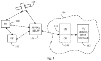
- Figure 1 depicts examples of simplified system architectures only showing some elements and functional entities, all being logical units, whose implementation may differ from what is shown.
- the connections shown in Figure 1 are logical connections; the actual physical connections may be different. It is apparent to a person skilled in the art that the system typically comprises also other functions and structures than those shown in Figure 1 .
- Figure 1 shows user devices 100 and 102 configured to be in a wireless connection on one or more communication channels in a cell with an access node (such as (e/g)NodeB) 104 providing the cell.
- the physical link from a user device to a (e/g)NodeB is called uplink or reverse link and the physical link from the (e/g)NodeB to the user device is called downlink or forward link.
- (e/g)NodeBs or their functionalities may be implemented by using any node, host, server or access point etc. entity suitable for such a usage.
- a communications system typically comprises more than one (e/g)NodeB in which case the (e/g)NodeBs may also be configured to communicate with one another over links, wired or wireless, designed for the purpose. These links may be used for signaling purposes.
- the (e/g)NodeB is a computing device configured to control the radio resources of communication system it is coupled to.
- the NodeB may also be referred to as a base station, an access point or any other type of interfacing device including a relay station capable of operating in a wireless environment.
- the (e/g)NodeB includes or is coupled to transceivers. From the transceivers of the (e/g)NodeB, a connection is provided to an antenna unit that establishes bi-directional radio links to user devices.
- the antenna unit may comprise a plurality of antennas or antenna elements.
- the (e/g)NodeB is further connected to core network 110 (CN or next generation core NGC).
- core network 110 CN or next generation core NGC.
- the counterpart on the CN side can be a serving gateway (S-GW, routing and forwarding user data packets), packet data network gateway (P-GW), for providing connectivity of user devices (UEs) to external packet data networks, or mobile management entity (MME), etc.
- S-GW serving gateway
- P-GW packet data network gateway
- MME mobile management entity
- the user device also called UE, user equipment, user terminal, terminal device, etc.
- UE user equipment
- user terminal terminal device
- any feature described herein with a user device may be implemented with a corresponding apparatus, such as a relay node.
- a relay node is a layer 3 relay (self-backhauling relay) towards the base station.
- the user device typically refers to a portable computing device that includes wireless mobile communication devices operating with or without a subscriber identification module (SIM), including, but not limited to, the following types of devices: a mobile station (mobile phone), smartphone, personal digital assistant (PDA), handset, device using a wireless modem (alarm or measurement device, etc.), laptop and/or touch screen computer, tablet, game console, notebook, and multimedia device.
- SIM subscriber identification module
- a user device may also be a nearly exclusive uplink only device, of which an example is a camera or video camera loading images or video clips to a network.
- Edge cloud may be brought into radio access network (RAN) by utilizing network function virtualization (NVF) and software defined networking (SDN).
- RAN radio access network
- NVF network function virtualization
- SDN software defined networking
- Using edge cloud may mean access node operations to be carried out, at least partly, in a server, host or node operationally coupled to a remote radio head or base station comprising radio parts. It is also possible that node operations will be distributed among a plurality of servers, nodes or hosts.
- Application of cloudRAN architecture enables RAN real time functions being carried out at the RAN side (in a distributed unit, DU 104) and non-real time functions being carried out in a centralized manner (in a centralized unit, CU 108).
- the third report may be transmitted to another access node such as the neighboring access node.
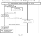
- the first and second RX-TX delays included in the third report may correspond to the first and second RX-TX delays of the terminal device as calculated in block 609 or, if the first and second shifts of timing ⁇ t 1 and ⁇ t 2 were applied, respectively, on the first and second RX-TX delay of the terminal device in block 611, to adjusted first and second RX-TX delays.
- the serving access node or said another access node transmits, in message 622, a fourth report comprising the first and second RX-TX delays to the LMF.
- Figure 6A the positioning of the terminal device was carried out by the LMF, in other embodiments, the positioning of the terminal device may be carried out, additionally or alternatively, locally by the terminal device.
- Figure 6B illustrates processes according to embodiments for performing (multi-RTT) positioning locally by the terminal device itself.
- Figure 6B corresponds to a large extent to Figure 6A and any of the definitions provided in connection with Figure 6A apply, mutatis mutandis, for Figure 6B .
- the terminal device calculates, in block 630, a position of the terminal device based on the first and second RTTs and the first and second RX-TX delays of the terminal device (and known locations of the serving access node and the neighboring access node). This calculation may be carried out similar to the calculation in block 624 of Figure 6A (though the entity performing the calculation is obviously different).
- the calculated position of the terminal device may be displayed to a user of the terminal device via a display of the terminal device (e.g., using a dedicated positioning or map application installed to the terminal device) and/or information on the position of the terminal device may be transmitted, by the terminal device, to the serving access node of the terminal device.
- Figures 6A and 6B illustrate multi-RTT positioning procedures involving a serving access node and a single neighboring access node
- the multi-RTT positioning may involve a serving access node and a plurality of neighboring access nodes.
- the multi-RTT procedure for the plurality of neighboring access nodes may be carried out in a similar manner as illustrated in Figure 6A or 6B for the single neighboring access node.
- elements 605, 606, 616 to 619 of Figure 6A may be omitted and the elements 609 to 611, 620 to 624 of Figure 6A may be modified to correspond only to the first positioning or sounding reference signal or to any quantities derived therefrom (e.g., first RX-TX delay and/or a first shift of timing).
- first RX-TX delay and/or a first shift of timing e.g., first RX-TX delay and/or a first shift of timing
- the terminal device may report its capability to a serving access node (or other access node) to compensate. This may be done, e.g., as a part of general terminal device capability reporting.
- the terminal device may be configured to report, to the (serving) access node of the terminal device, capability of the terminal device of being able to apply the shift of transmission timing (e.g., in the first process of Figure 3 or the embodiment of Figure 4 ), the shift of reception timing (e.g., in the second process of Figure 3 or the embodiment of Figure 5 ) or the shift of timing (e.g., in the embodiments of Figures 6A and 6B ) for compensating for the frequency shift of the local reference clock.
- the shift of transmission timing e.g., in the first process of Figure 3 or the embodiment of Figure 4
- the shift of reception timing e.g., in the second process of Figure 3 or the embodiment of Figure 5
- the shift of timing e.g., in the embodiments of Figures 6A and 6B
- the report may comprise information on which type of compensation is carried out (namely, adjustment of the transmission timing or adjustment of the RX-TX delay as described in connection with block 611 of Figure 6A ).
- type of compensation namely, adjustment of the transmission timing or adjustment of the RX-TX delay as described in connection with block 611 of Figure 6A .
- the embodiments discussed above may provide at least some of the following advantages or technical effects.
- the solutions according to embodiments may enable increasing the accuracy of any terminal device positioning scheme impacted by frequency updates of the local reference clock of the terminal device in-between any two measurements and/or transmissions for which the relative timing impacts the position estimation accuracy.
- positioning reference signals as downlink reference signals for positioning and sounding reference signals as uplink reference signals for positioning
- different types of downlink and/or uplink reference signals may be used, instead of the positioning reference signal and/or the sounding reference signal, respectively.
- the used downlink and uplink reference signal may be specifically any downlink and uplink reference signals suitable for positioning.
- Figure 7 illustrates an apparatus 701 configured to carry out the functions described above in connection with a terminal device such as the first and/or second terminal device shown in Figure 3 and/or the terminal device of any of Figures 4 to 5 , 6A and 6B .
- the apparatus may be an electronic device comprising electronic circuitries.
- the apparatus may be a separate network entity or a plurality of separate entities.
- the apparatus may comprise a communication control circuitry 720, such as at least one processor, and at least one memory 730 including a computer program code (software) 731 wherein the at least one memory and the computer program code (software) are configured, with the at least one processor, to cause the apparatus to carry out any one of the embodiments of the relay node described above.
- the apparatus 701 may comprise the phase-locked loop of Figure 2 .
- the memory 730 may comprise a database 732 which may comprise information, for example, on SRS and/or PRS configurations, (shifted) transmission time instances (i.e., TODs), (shifted) reception time instances (i.e., TOAs), frequency shifts, frequency-shift time instances, shifts of transmission, reception or other timing, as described in previous embodiments.
- the memory 730 may also comprise other databases which may not be related to the described functionalities according to embodiments.
- circuitry also covers an implementation of merely a hardware circuit or processor (or multiple processors) or portion of a hardware circuit or processor and its (or their) accompanying software and/or firmware.
- circuitry also covers, for example and if applicable to the particular claim element, a baseband integrated circuit or processor integrated circuit for a mobile device or a similar integrated circuit in server, a cellular network device, or other computing or network device.
Landscapes
- Engineering & Computer Science (AREA)
- Signal Processing (AREA)
- Computer Networks & Wireless Communication (AREA)
- Physics & Mathematics (AREA)
- General Physics & Mathematics (AREA)
- Radar, Positioning & Navigation (AREA)
- Remote Sensing (AREA)
- Astronomy & Astrophysics (AREA)
- Aviation & Aerospace Engineering (AREA)
- Mobile Radio Communication Systems (AREA)
Claims (15)
- Vorrichtung für ein erstes Endgerät, wobei die Vorrichtung Mittel umfasst zum:Übertragen eines ersten Uplink-Referenzsignals zu einem ersten Übertragungszeitpunkt, der gemäß einem lokalen Referenztakt des ersten Endgeräts gemessen wird;Anwenden einer Frequenzverschiebung auf eine Frequenz des lokalen Referenztakts zu einem Frequenzverschiebungszeitpunkt, der gemäß dem lokalen Referenztakt gemessen wird und auf den ersten Zeitpunkt folgt;Berechnen einer Verschiebung der Übertragungszeit für eine bevorstehende Übertragung eines zweiten Uplink-Referenzsignals zum Kompensieren der Frequenzverschiebung basierend auf einem zweiten Übertragungszeitpunkt, der unter Verwendung des lokalen Referenztakts für die bevorstehende Übertragung des zweiten Uplink-Referenzsignals, der Frequenzverschiebung und dem Frequenzverschiebungszeitpunkt geplant ist;Anwenden der Verschiebung der Übertragungszeit auf den zweiten Übertragungszeitpunkt; undÜbertragen des zweiten Uplink-Referenzsignals zum zweiten Zeitpunkt nach der Verschiebung der Übertragungszeit.
- Vorrichtung nach Anspruch 1, wobei die Vorrichtung ferner Mittel umfasst zum:
Berechnen der Verschiebung der Übertragungszeit ferner basierend auf dem ersten Übertragungszeitpunkt. - Vorrichtung nach Anspruch 1 oder 2, wobei die Vorrichtung ferner Mittel umfasst zum:
Melden, an einen bedienenden Zugangsknoten, der Fähigkeit des ersten Endgeräts, die Verschiebung der Übertragungszeit zur Kompensation der Frequenzverschiebung des lokalen Referenztakts anwenden zu können. - Vorrichtung nach Anspruch 2 oder 3, wobei die Vorrichtung Mittel zum Übertragen des ersten Uplink-Referenzsignals an mindestens einen ersten Zugangsknoten und/oder zum Übertragen des zweiten Uplink-Referenzsignals an den mindestens einen ersten Zugangsknoten und/oder mindestens einen zweiten Zugangsknoten umfasst.
- Vorrichtung nach Anspruch 2 oder 3, wobei das erste Endgerät für die Strahlformung bei der Übertragung unter Verwendung eines oder mehrerer Antennenarrays konfiguriert ist und die Vorrichtung Mittel zum Übertragen des ersten Uplink-Referenzsignals an einen ersten Zugangsknoten unter Verwendung eines ersten Strahls und zum Übertragen des zweiten Uplink-Referenzsignals an mindestens einen von dem ersten Zugangsknoten und einem zweiten Zugangsknoten unter Verwendung eines zweiten Strahls umfasst.
- Vorrichtung nach einem der Ansprüche 2 bis 5, wobei die Vorrichtung Mittel umfasst, um vor dem Übertragen des ersten Uplink-Referenzsignals:von einem bedienenden Zugangsknoten eine Konfigurationsnachricht zu empfangen, die Uplink-Referenzsignalressourcen zumindest für das Übertragen des ersten und des zweiten Uplink-Referenzsignals definiert; unddas erste Endgerät gemäß der Konfigurationsnachricht zu konfigurieren.
- Vorrichtung für ein zweites Endgerät, wobei die Vorrichtung Mittel umfasst zum:Empfangen eines ersten Downlink-Referenzsignals zu einem ersten Empfangszeitpunkt, der gemäß einem lokalen Referenztakt des zweiten Endgeräts gemessen wird;Anwenden einer Frequenzverschiebung auf eine Frequenz des lokalen Referenztakts zu einem Frequenzverschiebungszeitpunkt, wobei der Frequenzverschiebungszeitpunkt gemäß dem lokalen Referenztakt definiert ist und auf den ersten Empfangszeitpunkt folgt;Empfangen eines zweiten Downlink-Referenzsignals zu einem zweiten Empfangszeitpunkt, der gemäß dem lokalen Referenztakt gemessen wird;Berechnen einer Verschiebung der Empfangszeit für den Empfang des zweiten Downlink-Referenzsignals zum Kompensieren der Frequenzverschiebung basierend auf der Frequenzverschiebung, dem Frequenzverschiebungszeitpunkt und dem zweiten Empfangszeitpunkt;Berechnen einer angepassten Referenzsignal-Zeitdifferenz basierend auf dem ersten Empfangszeitpunkt, dem zweiten Empfangszeitpunkt und der Verschiebung der Empfangszeit; undDurchführen von mindestens einem vonMelden der angepassten Referenzsignal-Zeitdifferenz an einen bedienenden Zugangsknoten undBerechnen einer Position des zweiten Endgeräts basierend zumindest auf der angepassten Referenzsignal-Zeitdifferenz gemäß den Prinzipien der Positionierung anhand der beobachteten Ankunftszeitdifferenz.
- Vorrichtung nach Anspruch 7, wobei die Vorrichtung ferner Mittel zur Berechnung der Verschiebung der Empfangszeit basierend auf dem ersten Empfangszeitpunkt umfasst.
- Vorrichtung nach Anspruch 7 oder 8, wobei die Vorrichtung ferner Mittel umfasst zum:
Melden, an den bedienenden Zugangsknoten, der Fähigkeit des zweiten Endgeräts, die Verschiebung der Empfangszeit zur Kompensation der Frequenzverschiebung des lokalen Referenztakts anwenden zu können. - Vorrichtung nach Anspruch 7 oder 9, wobei die Vorrichtung Mittel zum Empfangen des ersten Downlink-Referenzsignals von einem ersten Zugangsknoten und/oder zum Empfangen des zweiten Downlink-Referenzsignals von dem ersten Zugangsknoten oder einem zweiten Zugangsknoten umfasst.
- Vorrichtung nach Anspruch 7 oder 9, wobei das zweite Endgerät für die Strahlformung bei dem Empfang unter Verwendung eines oder mehrerer Antennenarrays konfiguriert ist und die Vorrichtung Mittel zum Empfangen des ersten Downlink-Referenzsignals von einem ersten Zugangsknoten unter Verwendung eines ersten Strahls und zum Empfangen des zweiten Downlink-Referenzsignals von einem von dem ersten Zugangsknoten und einem zweiten Zugangsknoten unter Verwendung eines zweiten Strahls umfasst.
- Vorrichtung nach einem der Ansprüche 7 bis 11, wobei die Vorrichtung Mittel umfasst, um vor dem Empfangen des ersten Downlink-Referenzsignals:von einem bedienenden Zugangsknoten eine Konfigurationsnachricht zu empfangen, die Downlink-Referenzsignalressourcen zumindest für das Empfangen des ersten und des zweiten Downlink-Referenzsignals definiert; unddas zweite Endgerät gemäß der Konfigurationsnachricht zu konfigurieren.
- Vorrichtung für ein drittes Endgerät, wobei die Vorrichtung Mittel umfasst zum:Empfangen eines ersten Downlink-Referenzsignals zu einem ersten Empfangszeitpunkt, der gemäß einem lokalen Referenztakt des dritten Endgeräts gemessen wird, von einem ersten Zugangsknoten;Anwenden einer Frequenzverschiebung auf eine Frequenz des lokalen Referenztakts zu einem Frequenzverschiebungszeitpunkt, wobei der Frequenzverschiebungszeitpunkt gemäß dem lokalen Referenztakt gemessen wird und auf die ersten Empfangszeitpunkte folgt;Berechnen einer ersten Empfangs-Übertragungs-Verzögerung des Endgeräts zwischen dem ersten Empfangszeitpunkt und einem ersten Übertragungszeitpunkt, der für die Übertragung eines ersten Uplink-Referenzsignals geplant ist;Berechnen einer ersten Zeitverschiebung zum Kompensieren der Frequenzverschiebung basierend auf dem ersten Übertragungszeitpunkt, der Frequenzverschiebung und dem Frequenzverschiebungszeitpunkt;Anwenden der ersten Zeitverschiebung auf eines von dem ersten Übertragungszeitpunkt und der ersten Empfangs-Übertragungs-Verzögerung;Übertragen des ersten Uplink-Referenzsignals zum ersten Übertragungszeitpunkt an den ersten Zugangsknoten; undDurchführen von mindestens einem vonMelden der ersten Empfangs-Übertragungs-Verzögerung an mindestens einen von dem ersten Zugangsknoten und einem zweiten Zugangsknoten undEmpfangen von Informationen über eine erste Umlaufzeit, die basierend auf einer Übertragung des ersten Downlink-Referenzsignals und dem Empfang des ersten Uplink-Referenzsignals von dem ersten Zugangsknoten berechnet wird, und Schätzen einer Position des dritten Endgeräts basierend auf mindestens der ersten Umlaufzeit und der ersten Empfangs-Übertragungs-Verzögerung.
- Verfahren, umfassend:Übertragen eines ersten Uplink-Referenzsignals zu einem ersten Übertragungszeitpunkt, der gemäß einem lokalen Referenztakt eines ersten Endgeräts gemessen wird;Anwenden einer Frequenzverschiebung auf eine Frequenz des lokalen Referenztakts zu einem Frequenzverschiebungszeitpunkt, der gemäß dem lokalen Referenztakt gemessen wird und auf den ersten Zeitpunkt folgt;Berechnen einer Verschiebung der Übertragungszeit für eine bevorstehende Übertragung eines zweiten Uplink-Referenzsignals zum Kompensieren der Frequenzverschiebung basierend auf einem zweiten Übertragungszeitpunkt, der unter Verwendung des lokalen Referenztakts für die bevorstehende Übertragung des zweiten Uplink-Referenzsignals, der Frequenzverschiebung und dem Frequenzverschiebungszeitpunkt geplant ist;Anwenden der Verschiebung der Übertragungszeit auf den zweiten Übertragungszeitpunkt; undÜbertragen des zweiten Uplink-Referenzsignals zum zweiten Zeitpunkt nach der Verschiebung der Übertragungszeit.
- Computerprogramm mit Anweisungen, die, wenn sie von einer Vorrichtung ausgeführt werden, die Vorrichtung veranlassen, mindestens Folgendes durchzuführen:Übertragen eines ersten Uplink-Referenzsignals zu einem ersten Übertragungszeitpunkt, der gemäß einem lokalen Referenztakt eines ersten Endgeräts gemessen wird;Anwenden einer Frequenzverschiebung auf eine Frequenz des lokalen Referenztakts zu einem Frequenzverschiebungszeitpunkt, der gemäß dem lokalen Referenztakt gemessen wird und auf den ersten Zeitpunkt folgt;Berechnen einer Verschiebung der Übertragungszeit für eine bevorstehende Übertragung eines zweiten Uplink-Referenzsignals zum Kompensieren der Frequenzverschiebung basierend auf einem zweiten Übertragungszeitpunkt, der unter Verwendung des lokalen Referenztakts für die bevorstehende Übertragung des zweiten Uplink-Referenzsignals, der Frequenzverschiebung und dem Frequenzverschiebungszeitpunkt geplant ist;Anwenden der Verschiebung der Übertragungszeit auf den zweiten Übertragungszeitpunkt; undÜbertragen des zweiten Uplink-Referenzsignals zum zweiten Zeitpunkt nach der Verschiebung der Übertragungszeit.
Applications Claiming Priority (2)
| Application Number | Priority Date | Filing Date | Title |
|---|---|---|---|
| FI20206264 | 2020-12-08 | ||
| PCT/FI2021/050807 WO2022123109A1 (en) | 2020-12-08 | 2021-11-25 | Frequency reference adjustment compensation for positioning |
Publications (3)
| Publication Number | Publication Date |
|---|---|
| EP4238364A1 EP4238364A1 (de) | 2023-09-06 |
| EP4238364A4 EP4238364A4 (de) | 2024-05-22 |
| EP4238364B1 true EP4238364B1 (de) | 2025-06-25 |
Family
ID=81973175
Family Applications (1)
| Application Number | Title | Priority Date | Filing Date |
|---|---|---|---|
| EP21902767.9A Active EP4238364B1 (de) | 2020-12-08 | 2021-11-25 | Frequenzreferenzeinstellungskompensation zur positionierung |
Country Status (4)
| Country | Link |
|---|---|
| US (1) | US12520270B2 (de) |
| EP (1) | EP4238364B1 (de) |
| CN (1) | CN116830688A (de) |
| WO (1) | WO2022123109A1 (de) |
Families Citing this family (2)
| Publication number | Priority date | Publication date | Assignee | Title |
|---|---|---|---|---|
| WO2022141596A1 (zh) * | 2020-12-31 | 2022-07-07 | 北京小米移动软件有限公司 | 接收控制方法和装置 |
| EP4418567A1 (de) * | 2023-02-14 | 2024-08-21 | Nokia Technologies Oy | Verfahren, vorrichtungen und systeme zur multi-rtt-positionierung in einem nicht terrestrischen netzwerk |
Family Cites Families (12)
| Publication number | Priority date | Publication date | Assignee | Title |
|---|---|---|---|---|
| BR0115959A (pt) * | 2000-11-14 | 2005-05-03 | Symbol Technologies Inc | Método e aparelhos para identificação de localização de objeto em rede de comunicação |
| US6724342B2 (en) | 2002-04-19 | 2004-04-20 | Sirf Technology, Inc. | Compensation for frequency adjustment in mobile communication-positioning device with shared oscillator |
| US7957343B2 (en) | 2008-03-06 | 2011-06-07 | Qualcomm Incorporated | Motion-aware mobile time and frequency tracking |
| WO2014027942A1 (en) | 2012-08-13 | 2014-02-20 | Telefonaktiebolaget L M Ericsson (Publ) | Enhancing positioning with transmit-timing adjustment information |
| US8923464B2 (en) | 2012-11-16 | 2014-12-30 | Qualcomm Incorporated | Methods and apparatus for enabling distributed frequency synchronization |
| US10285153B2 (en) | 2014-11-12 | 2019-05-07 | Industry-University Cooperation Foundation Hanyang University | Method and apparatus for transmitting positioning reference signal |
| US9913233B2 (en) * | 2015-07-28 | 2018-03-06 | Qualcomm Incorporated | Synchronization for device-to-device positioning in wireless networks |
| EP3837790A1 (de) * | 2018-08-17 | 2021-06-23 | Telefonaktiebolaget Lm Ericsson (Publ) | Bereitstellung von positionierungsreferenzsignalen |
| US11606705B2 (en) | 2018-10-05 | 2023-03-14 | Qualcomm Incorporated | System and methods for rapid round-trip-time measurement distribution |
| EP4075685B1 (de) * | 2018-10-12 | 2024-04-03 | OQ Technology S.à r.l. | Verfahren und system für nichtterrestrische zellulare drahtlose kommunikationsnetze |
| CN113438724B (zh) | 2019-03-18 | 2022-03-25 | 大唐移动通信设备有限公司 | 时钟偏移确定及其处理方法、装置、系统 |
| US11751082B2 (en) * | 2019-05-21 | 2023-09-05 | Qualcomm Incorporated | Reporting of information related to sounding reference signals (SRS) timing adjustments |
-
2021
- 2021-11-25 EP EP21902767.9A patent/EP4238364B1/de active Active
- 2021-11-25 CN CN202180093146.3A patent/CN116830688A/zh active Pending
- 2021-11-25 WO PCT/FI2021/050807 patent/WO2022123109A1/en not_active Ceased
- 2021-11-25 US US18/256,233 patent/US12520270B2/en active Active
Also Published As
| Publication number | Publication date |
|---|---|
| EP4238364A4 (de) | 2024-05-22 |
| US20240023051A1 (en) | 2024-01-18 |
| EP4238364A1 (de) | 2023-09-06 |
| WO2022123109A1 (en) | 2022-06-16 |
| US12520270B2 (en) | 2026-01-06 |
| CN116830688A (zh) | 2023-09-29 |
Similar Documents
| Publication | Publication Date | Title |
|---|---|---|
| US12250654B2 (en) | Clock synchronization | |
| US20240292347A1 (en) | Adjusting uplink synchronization timer | |
| US20230262624A1 (en) | Timing uncertainty in sidelink time synchronization | |
| EP4238364B1 (de) | Frequenzreferenzeinstellungskompensation zur positionierung | |
| US20240323903A1 (en) | Apparatus Comprising a Transceiver, Method for Performing Position Determination and Positioning System | |
| US11943729B2 (en) | Network time monitoring and adjustment | |
| US12177804B2 (en) | Synchronizing terminal device to network clock | |
| US20240357533A1 (en) | Apparatus, methods, and computer programs for propagation delay determination | |
| US12241986B1 (en) | UTC traceability support for terminal devices | |
| US20230188290A1 (en) | Coupled downlink and uplink reference signals for efficient multi-rtt positioning | |
| US20240406916A1 (en) | Indicating transmission timing changes | |
| US20250038825A1 (en) | Defining a timeline for fast uplink beam and/or panel selection | |
| US20230328682A1 (en) | Determining timing offset for improved positioning accuracy | |
| HK40113441A (en) | Utc traceability support for terminal devices | |
| HK40113441B (en) | Utc traceability support for terminal devices | |
| WO2026008723A1 (en) | Cell-free communication and positioning solutions | |
| WO2026008722A1 (en) | Cell-free positioning and communication solutions | |
| WO2024170085A1 (en) | Time alignment error grouping for multiple transmission-reception points | |
| EP4449651A1 (de) | Konfliktvermeidung für referenzsignal |
Legal Events
| Date | Code | Title | Description |
|---|---|---|---|
| STAA | Information on the status of an ep patent application or granted ep patent |
Free format text: STATUS: THE INTERNATIONAL PUBLICATION HAS BEEN MADE |
|
| PUAI | Public reference made under article 153(3) epc to a published international application that has entered the european phase |
Free format text: ORIGINAL CODE: 0009012 |
|
| STAA | Information on the status of an ep patent application or granted ep patent |
Free format text: STATUS: REQUEST FOR EXAMINATION WAS MADE |
|
| 17P | Request for examination filed |
Effective date: 20230602 |
|
| AK | Designated contracting states |
Kind code of ref document: A1 Designated state(s): AL AT BE BG CH CY CZ DE DK EE ES FI FR GB GR HR HU IE IS IT LI LT LU LV MC MK MT NL NO PL PT RO RS SE SI SK SM TR |
|
| DAV | Request for validation of the european patent (deleted) | ||
| DAX | Request for extension of the european patent (deleted) | ||
| A4 | Supplementary search report drawn up and despatched |
Effective date: 20240422 |
|
| RIC1 | Information provided on ipc code assigned before grant |
Ipc: H04L 7/00 20060101ALI20240416BHEP Ipc: G01S 11/08 20060101ALI20240416BHEP Ipc: G01S 5/02 20100101ALI20240416BHEP Ipc: G01S 5/14 20060101ALI20240416BHEP Ipc: H04W 24/10 20090101ALI20240416BHEP Ipc: H04W 64/00 20090101ALI20240416BHEP Ipc: H04W 56/00 20090101AFI20240416BHEP |
|
| GRAP | Despatch of communication of intention to grant a patent |
Free format text: ORIGINAL CODE: EPIDOSNIGR1 |
|
| STAA | Information on the status of an ep patent application or granted ep patent |
Free format text: STATUS: GRANT OF PATENT IS INTENDED |
|
| INTG | Intention to grant announced |
Effective date: 20250120 |
|
| GRAS | Grant fee paid |
Free format text: ORIGINAL CODE: EPIDOSNIGR3 |
|
| GRAA | (expected) grant |
Free format text: ORIGINAL CODE: 0009210 |
|
| STAA | Information on the status of an ep patent application or granted ep patent |
Free format text: STATUS: THE PATENT HAS BEEN GRANTED |
|
| AK | Designated contracting states |
Kind code of ref document: B1 Designated state(s): AL AT BE BG CH CY CZ DE DK EE ES FI FR GB GR HR HU IE IS IT LI LT LU LV MC MK MT NL NO PL PT RO RS SE SI SK SM TR |
|
| REG | Reference to a national code |
Ref country code: GB Ref legal event code: FG4D |
|
| REG | Reference to a national code |
Ref country code: CH Ref legal event code: EP |
|
| REG | Reference to a national code |
Ref country code: CH Ref legal event code: EP |
|
| REG | Reference to a national code |
Ref country code: IE Ref legal event code: FG4D |
|
| REG | Reference to a national code |
Ref country code: DE Ref legal event code: R096 Ref document number: 602021033093 Country of ref document: DE |
|
| PG25 | Lapsed in a contracting state [announced via postgrant information from national office to epo] |
Ref country code: FI Free format text: LAPSE BECAUSE OF FAILURE TO SUBMIT A TRANSLATION OF THE DESCRIPTION OR TO PAY THE FEE WITHIN THE PRESCRIBED TIME-LIMIT Effective date: 20250625 |
|
| REG | Reference to a national code |
Ref country code: LT Ref legal event code: MG9D |
|
| PG25 | Lapsed in a contracting state [announced via postgrant information from national office to epo] |
Ref country code: NO Free format text: LAPSE BECAUSE OF FAILURE TO SUBMIT A TRANSLATION OF THE DESCRIPTION OR TO PAY THE FEE WITHIN THE PRESCRIBED TIME-LIMIT Effective date: 20250925 Ref country code: GR Free format text: LAPSE BECAUSE OF FAILURE TO SUBMIT A TRANSLATION OF THE DESCRIPTION OR TO PAY THE FEE WITHIN THE PRESCRIBED TIME-LIMIT Effective date: 20250926 |
|
| PG25 | Lapsed in a contracting state [announced via postgrant information from national office to epo] |
Ref country code: BG Free format text: LAPSE BECAUSE OF FAILURE TO SUBMIT A TRANSLATION OF THE DESCRIPTION OR TO PAY THE FEE WITHIN THE PRESCRIBED TIME-LIMIT Effective date: 20250625 |
|
| PG25 | Lapsed in a contracting state [announced via postgrant information from national office to epo] |
Ref country code: HR Free format text: LAPSE BECAUSE OF FAILURE TO SUBMIT A TRANSLATION OF THE DESCRIPTION OR TO PAY THE FEE WITHIN THE PRESCRIBED TIME-LIMIT Effective date: 20250625 |
|
| PGFP | Annual fee paid to national office [announced via postgrant information from national office to epo] |
Ref country code: FR Payment date: 20250930 Year of fee payment: 5 |
|
| PG25 | Lapsed in a contracting state [announced via postgrant information from national office to epo] |
Ref country code: RS Free format text: LAPSE BECAUSE OF FAILURE TO SUBMIT A TRANSLATION OF THE DESCRIPTION OR TO PAY THE FEE WITHIN THE PRESCRIBED TIME-LIMIT Effective date: 20250925 |
|
| PG25 | Lapsed in a contracting state [announced via postgrant information from national office to epo] |
Ref country code: LV Free format text: LAPSE BECAUSE OF FAILURE TO SUBMIT A TRANSLATION OF THE DESCRIPTION OR TO PAY THE FEE WITHIN THE PRESCRIBED TIME-LIMIT Effective date: 20250625 |
|
| REG | Reference to a national code |
Ref country code: NL Ref legal event code: MP Effective date: 20250625 |
|
| PG25 | Lapsed in a contracting state [announced via postgrant information from national office to epo] |
Ref country code: NL Free format text: LAPSE BECAUSE OF FAILURE TO SUBMIT A TRANSLATION OF THE DESCRIPTION OR TO PAY THE FEE WITHIN THE PRESCRIBED TIME-LIMIT Effective date: 20250625 |
|
| PG25 | Lapsed in a contracting state [announced via postgrant information from national office to epo] |
Ref country code: PT Free format text: LAPSE BECAUSE OF FAILURE TO SUBMIT A TRANSLATION OF THE DESCRIPTION OR TO PAY THE FEE WITHIN THE PRESCRIBED TIME-LIMIT Effective date: 20251027 |
|
| REG | Reference to a national code |
Ref country code: AT Ref legal event code: MK05 Ref document number: 1807979 Country of ref document: AT Kind code of ref document: T Effective date: 20250625 |
|
| PG25 | Lapsed in a contracting state [announced via postgrant information from national office to epo] |
Ref country code: IS Free format text: LAPSE BECAUSE OF FAILURE TO SUBMIT A TRANSLATION OF THE DESCRIPTION OR TO PAY THE FEE WITHIN THE PRESCRIBED TIME-LIMIT Effective date: 20251025 |
|
| PGFP | Annual fee paid to national office [announced via postgrant information from national office to epo] |
Ref country code: DE Payment date: 20250930 Year of fee payment: 5 |
|
| PGFP | Annual fee paid to national office [announced via postgrant information from national office to epo] |
Ref country code: GB Payment date: 20251001 Year of fee payment: 5 |
|
| PG25 | Lapsed in a contracting state [announced via postgrant information from national office to epo] |
Ref country code: AT Free format text: LAPSE BECAUSE OF FAILURE TO SUBMIT A TRANSLATION OF THE DESCRIPTION OR TO PAY THE FEE WITHIN THE PRESCRIBED TIME-LIMIT Effective date: 20250625 Ref country code: SM Free format text: LAPSE BECAUSE OF FAILURE TO SUBMIT A TRANSLATION OF THE DESCRIPTION OR TO PAY THE FEE WITHIN THE PRESCRIBED TIME-LIMIT Effective date: 20250625 |
|
| PG25 | Lapsed in a contracting state [announced via postgrant information from national office to epo] |
Ref country code: CZ Free format text: LAPSE BECAUSE OF FAILURE TO SUBMIT A TRANSLATION OF THE DESCRIPTION OR TO PAY THE FEE WITHIN THE PRESCRIBED TIME-LIMIT Effective date: 20250625 |
|
| PG25 | Lapsed in a contracting state [announced via postgrant information from national office to epo] |
Ref country code: PL Free format text: LAPSE BECAUSE OF FAILURE TO SUBMIT A TRANSLATION OF THE DESCRIPTION OR TO PAY THE FEE WITHIN THE PRESCRIBED TIME-LIMIT Effective date: 20250625 |
|
| PG25 | Lapsed in a contracting state [announced via postgrant information from national office to epo] |
Ref country code: EE Free format text: LAPSE BECAUSE OF FAILURE TO SUBMIT A TRANSLATION OF THE DESCRIPTION OR TO PAY THE FEE WITHIN THE PRESCRIBED TIME-LIMIT Effective date: 20250625 |
|
| PG25 | Lapsed in a contracting state [announced via postgrant information from national office to epo] |
Ref country code: SK Free format text: LAPSE BECAUSE OF FAILURE TO SUBMIT A TRANSLATION OF THE DESCRIPTION OR TO PAY THE FEE WITHIN THE PRESCRIBED TIME-LIMIT Effective date: 20250625 |
|
| PG25 | Lapsed in a contracting state [announced via postgrant information from national office to epo] |
Ref country code: ES Free format text: LAPSE BECAUSE OF FAILURE TO SUBMIT A TRANSLATION OF THE DESCRIPTION OR TO PAY THE FEE WITHIN THE PRESCRIBED TIME-LIMIT Effective date: 20250625 |