EP3972913B1 - Behälter mit griff am körper, der durch einen einzigen arbeitsgang geformt wird - Google Patents
Behälter mit griff am körper, der durch einen einzigen arbeitsgang geformt wird Download PDFInfo
- Publication number
- EP3972913B1 EP3972913B1 EP20724857.6A EP20724857A EP3972913B1 EP 3972913 B1 EP3972913 B1 EP 3972913B1 EP 20724857 A EP20724857 A EP 20724857A EP 3972913 B1 EP3972913 B1 EP 3972913B1
- Authority
- EP
- European Patent Office
- Prior art keywords
- container
- central axis
- predetermined height
- median line
- boxed
- Prior art date
- Legal status (The legal status is an assumption and is not a legal conclusion. Google has not performed a legal analysis and makes no representation as to the accuracy of the status listed.)
- Active
Links
Images


Classifications
-
- B—PERFORMING OPERATIONS; TRANSPORTING
- B65—CONVEYING; PACKING; STORING; HANDLING THIN OR FILAMENTARY MATERIAL
- B65D—CONTAINERS FOR STORAGE OR TRANSPORT OF ARTICLES OR MATERIALS, e.g. BAGS, BARRELS, BOTTLES, BOXES, CANS, CARTONS, CRATES, DRUMS, JARS, TANKS, HOPPERS, FORWARDING CONTAINERS; ACCESSORIES, CLOSURES, OR FITTINGS THEREFOR; PACKAGING ELEMENTS; PACKAGES
- B65D23/00—Details of bottles or jars not otherwise provided for
- B65D23/10—Handles
- B65D23/102—Gripping means formed in the walls, e.g. roughening, cavities, projections
-
- B—PERFORMING OPERATIONS; TRANSPORTING
- B65—CONVEYING; PACKING; STORING; HANDLING THIN OR FILAMENTARY MATERIAL
- B65D—CONTAINERS FOR STORAGE OR TRANSPORT OF ARTICLES OR MATERIALS, e.g. BAGS, BARRELS, BOTTLES, BOXES, CANS, CARTONS, CRATES, DRUMS, JARS, TANKS, HOPPERS, FORWARDING CONTAINERS; ACCESSORIES, CLOSURES, OR FITTINGS THEREFOR; PACKAGING ELEMENTS; PACKAGES
- B65D1/00—Rigid or semi-rigid containers having bodies formed in one piece, e.g. by casting metallic material, by moulding plastics, by blowing vitreous material, by throwing ceramic material, by moulding pulped fibrous material or by deep-drawing operations performed on sheet material
- B65D1/02—Bottles or similar containers with necks or like restricted apertures, designed for pouring contents
- B65D1/0223—Bottles or similar containers with necks or like restricted apertures, designed for pouring contents characterised by shape
-
- B—PERFORMING OPERATIONS; TRANSPORTING
- B65—CONVEYING; PACKING; STORING; HANDLING THIN OR FILAMENTARY MATERIAL
- B65D—CONTAINERS FOR STORAGE OR TRANSPORT OF ARTICLES OR MATERIALS, e.g. BAGS, BARRELS, BOTTLES, BOXES, CANS, CARTONS, CRATES, DRUMS, JARS, TANKS, HOPPERS, FORWARDING CONTAINERS; ACCESSORIES, CLOSURES, OR FITTINGS THEREFOR; PACKAGING ELEMENTS; PACKAGES
- B65D2501/00—Containers having bodies formed in one piece
- B65D2501/0009—Bottles or similar containers with necks or like restricted apertures designed for pouring contents
- B65D2501/0018—Ribs
- B65D2501/0036—Hollow circonferential ribs
Definitions
- the field of the invention is that of the design and manufacture of plastic containers.
- the invention relates to containers obtained by blowing or stretch-blowing from blanks (preforms, or intermediate containers having undergone one or more prior blowing operations) made of plastic.
- the manufacturing of a container by blowing comprises a step of introducing, into a mold in the shape of the container, a blank previously heated to a temperature higher than the glass transition temperature of the material constituting the preform (such such as PET), and a step of injecting a fluid (such as air) under pressure into the blank. Stretching using a sliding rod can complete the blowing.
- a container thus obtained has a shape defined by a body extending between a bottom and an opening.
- Gripping such containers may be more or less easy depending on the shape and volume of the container, as well as the size of the hands of the person who wishes to grasp the container.
- the handle is made on the body of the container, during the formation of the latter.
- the mold in which the container is blown has inserts, called handle boxing inserts, which are movable through the walls of the mold.
- the method of manufacturing a container with a gripping handle includes a step of boxing a handle using the inserts. Boxing consists of pushing an area of material towards the inside of the container, so as to form a hollow-shaped handle on the wall.
- the handle is formed by bringing together two portions of a wall of the container during its formation under the action of the boxing inserts. The boxing inserts thus deform the still softened plastic material.
- Boxing allows the creation of a recess having a significant depth on the wall of the body. The depth of this recess cannot be reached by simply blowing the container into its mold.
- the containers described in this document include a gripping handle formed by two boxed recesses presented by the body, facing each other, and thus bringing two opposite portions of the wall of the body of the container closer to each other.
- the boxed handle allows a person to more easily grip the container by inserting their thumb into one of the boxed recesses, wrapping their hand around the handle, and inserting their other fingers into the other boxed recess. The user can thus grab the handle to lift the container.
- the document JP2017128348A describes a container according to the preamble of claim 1.
- this double boxing causes constraints for the design of the mold used to form the container, and for the vertical positioning of the boxing inserts relative to the mold.
- the blowing pressure corresponds to the air injected into a preform placed in the mold to produce the container. This blowing pressure tends to push apart two parts of the mold pressed against each other to form the mold.
- Pneumatic compensation consists of injecting air into a chamber between one of the parts of the mold and its support to counteract the blowing pressure.
- the chamber is delimited between the part of the mold and its support by a compensation joint.
- the joint is arranged so that the projected surface of the compensation chamber is at least equal to that of the container taken in a plane parallel to the longitudinal axis of the container.
- the compensation zone which was personalized in the past in the applicant's machines, is now standardized and the compensation chamber has a position and dimensions which are the same whatever the surface. projected from the bottle.
- the height of the chamber is generally less than that of the container (the height is the dimension taken along the longitudinal axis of the container) and the width of the chamber is greater for that the projected surface of the chamber is at least equal to that of the container. Consequently, the bottom of the container, its neck and part of the shoulder face the outside of the clearing chamber.
- the boxing insert fitted to the compensated mold part must move within the perimeter defined by the compensation joint.
- the boxing insert passing through the compensated mold part must have a vertical positioning such that the axis of the gripping handle produced cannot be positioned less than 97mm from the neck of the container.
- the invention aims in particular to overcome the disadvantages of the prior art.
- the invention aims to propose a container having a gripping handle whose design limits the overconsumption of plastic material during the manufacture of the container, and this in particular compared to containers according to the prior art having a gripping handle formed by double boxing.
- the invention also aims to provide such a container which can be grasped equally and just as easily by the right hand or the left hand of a consumer.
- the container has a gripping handle constituted by the shape of the body itself on its predetermined height H.
- the body has a unique boxed gripping recess making it possible to improve gripping the body of the container.
- the gripping handle makes it possible to “pinch” the container to grasp it.
- the boxed gripping recess extends over the predetermined height and thus provides a housing in which at least one of the fingers of a hand (for example one or more of the fingers with the exception of the thumb or, on the contrary, only the thumb) can be inserted.
- the hand can then close on the body of the container so that the thumb comes into opposition relation to the body of the container, with respect to the other finger(s).
- the clamp thus formed by the hand allows effective gripping of the container, for a right-handed or a left-handed person, using the unique boxed recess.
- This grip is particularly ergonomic on containers with a small diameter (less than 100 mm).
- a container according to the invention can thus be lighter compared to a container having a gripping handle formed by double boxing.
- the production of a single boxing to form the gripping handle offers greater latitude in designing the mold for the container on the one hand, and increased possibilities in the design of the packaging since the positioning range of the mobile insert is more important, on the other hand.
- the boxing insert passing through the non-compensated mold part can have a vertical positioning such that the gripping handle produced can be found, relative to the container, at a height greater than that which is permitted for containers with a handle grip formed by double boxing, with a pneumatically compensated mold.
- the invention makes it possible to drastically reduce this distance: the boxed gripping recess can be much closer to the neck of the container.
- At least one deepest point of the center line of maximum depression is located 15 mm or less from the central axis C.
- the boxed gripping recess then has a sufficiently large depth for optimal insertion of the fingers of one hand, whatever the format of the bottle, and to allow the creation of a gripper using one hand on the container. .
- the maximum indentation center line describes the profile of the boxed indentation in the diametrical plane.
- the deepest point(s) corresponds to the point along this center line of maximum depression which is closest to the central axis C or which extends most beyond the central axis C in the diametrical plane, relative to at the other points constituting the center line of maximum depression.
- the center line of maximum depression has at its maximum depth a straight section parallel to the central axis C, then the points constituting this straight section are the deepest points of the center line of maximum depression.
- the deepest point(s) are located 5 mm or more from the central axis C.
- the creation of the boxed gripping recess during the formation of the container by stretch-blowing does not require unconventional adjustment of the stroke of the elongation rod used to stretch and hold the container. More precisely, during blowing, the elongation rod extends inside the preform along the central axis C to ensure that an amorphous point of the preform is well maintained at the bottom of the mold. This elongation rod thus occupies a space centered on the central axis C inside the container during its formation. Consequently, the position 5 millimeters or more from the central axis C of the deepest point(s) avoids contact between the boxed recess and the elongation rod. There is thus no need to raise the elongation rod early to allow boxing of the boxed gripping recess which would extend opposite the stroke of the elongation rod.
- the body has a first developed and a second developed on either side of the diametrical plane P of the body, between said deepest point and a point diametrically opposite said deepest point, the first developed and the second developed each being between 100 and 160 millimeters.
- the handle for gripping the container is thus particularly ergonomic.
- the body is symmetrical with respect to the diametrical plane over the predetermined height H.
- the container can be grasped with the right or left hand, equally and just as easily.
- the boxed gripping recess has on either side of the center line of maximum depression a right side panel and a left side panel respectively fitting into a first plane and a second plane which intersect according to an opening angle of between 25° and 45°.
- Such an opening of the boxed gripping recess promotes the correct insertion of at least one of the fingers of a person, whether right-handed or left-handed.
- the body has, on its predetermined height H and along the central axis C, a cross section which fits inside a circle whose diameter decreases from a high end of the predetermined height , then which increases to a lower end of the predetermined height.
- the body thus has more restricted dimensions at its predetermined height which make it easier to grip the container with one hand.
- a person grasps the container when he inserts fingers (for example from the index finger to the little finger) in the boxed gripping recess and surrounds the body with the rest of his palm to position his thumb in opposition to relative to the body and form a clamp.
- fingers for example from the index finger to the little finger
- the person can grasp the container by inserting their thumb into the boxed gripping recess and surround the body with the rest of their palm to come and position the other fingers in opposition to the body and form a clamp.
- the body has on its predetermined height H a constriction for positioning a finger diametrically opposite the boxed gripping recess, the function of which is to receive a finger in order to facilitate gripping of the container, as explained below .
- Such a positioning constriction makes it easier to grip the container using one hand: in fact, tests have shown that when gripping the container, the thumb is naturally lodged in this positioning constriction while at least one other finger fits naturally into the boxed gripping recess.
- the body has at least over its predetermined height H annular reinforcement corrugations, the positioning constriction being positioned between two annular corrugations.
- the body is thus reinforced on its predetermined height H, thus avoiding fragility of the container due to the presence of the positioning restriction.
- Such reinforcement is particularly important when the packaging requires a resistance that its weight and therefore the thickness of available PET cannot allow it to achieve.
- the positioning restriction is then visually integrated onto the body.
- the positioning constriction is located above mid-height of the boxed gripping recess.
- the boxed gripping recess has a profile favoring gripping the container using the handle formed on the body. Indeed, by presenting a radius of curvature less than that of the second portion, the first portion of the center line of maximum depression forms a greater stop than that formed by the second portion. This improves the way in which the weight of the container is exerted on the upper part of the finger(s) inserted in the boxed gripping recess. This also logically corresponds to the profile offered by the lengths of the four fingers of the hand, other than the thumb, when they are all inserted into the boxed recess.
- This design forms a housing allowing all fingers except the thumb to be ergonomically accommodated in the boxed gripping recess when gripping the container.
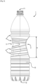
- a container 1 according to the invention comprises a body 10 which extends along a central axis C between an opening 11 and a bottom 12.
- the opening 11 is conventionally present at the end of a collar 13 located above a shoulder 14 surmounting the body 10.
- the container 1 is, according to the illustrated embodiments, a bottle made from a thermoplastic material such as PET (acronym for polyethylene terephthalate).
- the container 1 has a boxed gripping recess 2. This boxed gripping recess 2 extends parallel to the central axis C over a predetermined height H.
- Such a boxed recess is produced during the manufacture of the container 1 using a boxing insert which deforms the plastic material previously heated and blown into a molding cavity of a mold, to the shape of the container to be obtained , penetrating inside the mold.
- the boxed gripping recess 2 produced using a boxing insert, cannot be obtained by simply blowing a preform onto a specific shape of a mold (for example a protrusion projecting towards the interior of the molding cavity), and this in particular with regard to the depth of the boxed gripping recess 2. Indeed, as explained previously, the depth of a boxed recess is greater than the maximum achievable depth by blowing a preform onto a specific shape of a mold.
- the boxed gripping recess 2 has a center line 20 of maximum depression.
- This median line 20 of maximum depression corresponds to the profile of the boxing insert through the mold over the predetermined height H, and to the imprint that the boxing insert leaves on the container 1.
- the boxed gripping recess 2 also has, as illustrated by the figure 1 , a right side border 21 as well as a left side border 22.
- the right side border 21 and the left side border 22 frame the center line 20 of maximum depression.
- the median line 20 of maximum depression lies in a diametrical plane P which is equidistant from the right side edge 21 and the left side edge 22.
- This diametrical plane P corresponds to the views of figures 3 And 5 , and is represented on the figures 4 And 6 .
- boxed gripping recess 2 is the only boxed recess on the body 10 over the predetermined height H.
- the body 10 does not present any other boxing.
- the body 10 may, however, have other recesses which are not made by boxing to the predetermined height H.
- the deepest point 200 of the center line 20 of maximum depression is located 5 millimeters to 15 millimeters from the central axis C of the container 1 without the boxed gripping recess 2 interfering with the central axis C .
- the deepest point 200 of the center line 20 of maximum depression is located at a distance D of 7.5 millimeters from the central axis C.
- the boxing insert during the manufacture of this container 1, is moved along a translation axis, inscribed in a median plane of the insert, intersecting with the central axis C of the container.
- the container 1 can be formed by stretch blow molding.
- an elongation rod it is not necessary for an elongation rod to be raised in advance to allow the boxing of the boxed gripping recess 2 on, or in, or through, the volume occupied by this rod elongation when it is completely inserted inside the container 1.
- the body 10 is symmetrical with respect to the diametrical plane P over the predetermined height H.
- the boxed gripping recess 2 is detailed below with reference to the figures 3 to 6 .
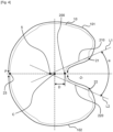
- the boxed gripping recess 2 has an opening angle ⁇ .
- the boxed gripping recess 2 has on either side of the center line 20 of maximum depression a right side panel 210 and a left side panel 220.
- the right side panel 210 fits into a first plane L1
- the left side pan 220 fits into a second plane L2.
- the first plane L1 and the second plane L2 intersect according to the opening angle ⁇ which is between 25° and 45°, and more preferably from 30° to 40°.
- This opening angle ⁇ is measured in a plane orthogonal to the central axis C.
- the opening angle ⁇ is equal to 35°. According to the embodiment illustrated by Figure 6 , the opening angle ⁇ is equal to 37°.
- first plane L1 and the second plane L2 intersect in a plane orthogonal to the central axis C and on the predetermined height H at a meeting point 5.
- This meeting point 5 is located behind the central axis C in relation to the boxed gripping recess 2.
- This meeting point 5 is also located in the diametrical plane P.
- the median line 20 of maximum depression is convex towards the central axis C, between a high end and a low end distant from the central axis C.
- the median line 20 of maximum penetration is curved between its upper and lower ends so that a central part of this median line 20 of maximum penetration is closer to the central axis C than said ends.
- the first portion 201 extends from the upper end of the center line 20 of maximum depression to the deepest point 200 of the center line 20 of maximum depression.
- the second portion 202 extends from the first portion 201, and in particular from the deepest point 200, to the lower end of the median line 20 of maximum depression.
- the first portion 201 has a radius of curvature R1
- the second portion 202 has a radius of curvature R2.
- the radius of curvature R1 is less than the radius of curvature R2.
- This design moves the deepest point 200 of the center line 20 of maximum depression above the mid-height M of the boxed gripping recess 2, that is to say towards the opening 11 of the container.
- the first portion 201 extends from the upper end of the center line 20 of maximum depression to the deepest point 200 of the center line 20 of maximum depression.
- the intermediate portion 203 extends from the first portion 201, and in particular from the deepest point 200, to an intermediate point 204 along the center line 20 of maximum depression.
- the second portion 202 extends from the intermediate portion 203, and in particular from the intermediate point 204, to the lower end of the median line 20 of maximum depression.
- the first portion 201 has a radius of curvature R1
- the second portion 202 has a radius of curvature R2.
- the intermediate portion 203 has a radius of curvature R3.
- the radius of curvature R1 and the radius of curvature R2 are such that the first portion 201 and the second portion 202 have a significant curvature, and are thus curved.
- the intermediate portion 203 is essentially straight.
- the radius of curvature R3 is so large that the intermediate portion 203 can be compared to a straight line.
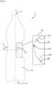
- the body 10 has, over its predetermined height H and along the central axis C, a cross section, such as that shown on the figure 4 , which fits inside a circle.
- the diameter of the circle decreases from a high end of the predetermined height H, that is to say towards the opening 11 of the container 1, then, after having reached a predetermined minimum diameter, increases to a lower end of the predetermined height H, that is to say towards the bottom 12 of the container 1.
- the container 1 presents a thinning over its predetermined height H.
- the body 10 has on its predetermined height H a positioning constriction 3 of a finger.
- This positioning constriction 3 is diametrically opposite the boxed gripping recess 2.
- This positioning restriction 3 is obtained thanks to the shape of the mold cavity.
- the positioning constriction 3 is obtained thanks to the blowing of the plastic material, during the production of the container 1, and thus to the application of the plastic material against the surface of the mold which has a shape complementary to that of the container 1 illustrated over there Figure 3 .
- the positioning constriction 3 is substantially smooth.
- the body 10 may have annular reinforcement corrugations 4, distributed regularly over its height. These annular reinforcement corrugations 4 are notably present on the predetermined height H.
- the annular reinforcement corrugations 4 over the predetermined height H can be configured so that the positioning constriction 3 is positioned between two adjacent annular corrugations 4.
- the annular corrugations 4 extend from the boxed gripping recess 2 oriented upwards, and below the positioning constriction 3, the corrugations annular rings 4 extend from the boxed gripping recess 2 while being oriented downwards.
- the two annular corrugations 4 which frame the positioning constriction 2 thus deviate from one another at the level of the positioning constriction 3.
- the positioning constriction 3 is located above the mid-height M of the boxed gripping recess 2.
- Such a container 1 according to the invention is more ergonomic when holding the bottle thanks to the presence of the boxed gripping recess 2 and the positioning constriction 3 of a finger.
- the user's fingers when grasping the container using one hand, the user's fingers, with the exception of the thumb, naturally insert themselves into the boxed gripping recess 2.
- the thumb of the hand is then oriented towards the opening 11 of the container.
- the position of the positioning recess 3, above the mid-height M of the boxed gripping recess 2 helps in natural positioning of the thumb for pinching the bottle.
- the body 10 has a first development 101 and a second development 102 on either side of the diametrical plane P of the body 10.
- the first developed 101 and the second developed 102 correspond to the periphery of the body 10, in a plane orthogonal to the central axis C, between the deepest point 200 and a point 23 diametrically opposite the deepest point 200.
- the lengths of the first developed 101 and second developed 102 are each between 100 and 160 millimeters.
- the first developed 101 and the second developed 102 are equal given that the body 10 is symmetrical with respect to the diametrical plane P over the predetermined height H.
- the first developed 101 and the second developed 102 are equal to 126 millimeters.
- the first developed 101 and the second developed 102 are equal to 140 millimeters.
Landscapes
- Engineering & Computer Science (AREA)
- Mechanical Engineering (AREA)
- Ceramic Engineering (AREA)
- Details Of Rigid Or Semi-Rigid Containers (AREA)
- Containers Having Bodies Formed In One Piece (AREA)
Claims (10)
- Behälter (1) aus Kunststoff, welcher einen Körper (10) umfasst, der sich entlang einer Mittelachse (C) zwischen einer Öffnung (11) und einem Boden (12) erstreckt, wobei der Körper (10) eine durch Boxing hergestellte Griffmulde (2) aufweist, die sich parallel zur Mittelachse (C) über eine vorbestimmte Höhe (H) erstreckt,wobei die durch Boxing hergestellte Griffmulde (2) die einzige an dem Körper (10) durch Boxing hergestellte Vertiefung über die vorbestimmte Höhe (H) ist und aufweist:- eine Mittellinie (20) maximaler Vertiefung;- einen rechten Seitenrand (21) und einen linken Seitenrand (22, welche die Mittellinie (20) maximaler Vertiefung umrahmen;wobei die Mittellinie (20) maximaler Vertiefung in einer vom rechten Seitenrand (21) und vom linken Seitenrand (22) äquidistanten diametralen Ebene (P) verläuft,dadurch gekennzeichnet, dass der Körper (10) eine erste Umrisslinie (101) und eine zweite Umrisslinie (102) auf jeweils einer Seite der diametralen Ebene (P) des Körpers (10) zwischen mindestens einem tiefsten Punkt (200) der Mittellinie (20) maximaler Vertiefung und einem diesem tiefsten Punkt (200) diametral gegenüberliegenden Punkt (23) aufweist, wobei die Längen der ersten Umrisslinie (101) und der zweiten Umrisslinie (102) jeweils 100 bis 160 mm betragen,und dadurch, dass die durch Boxing hergestellte Griffmulde (2) beiderseits der Mittellinie (20) maximaler Vertiefung eine rechte Seitenwand (210) und eine linke Seitenwand (220) aufweist, die in einer ersten Ebene (L1) bzw. einer zweiten Ebene (L2) liegen, welche sich unter einem Öffnungswinkel zwischen 25° und 45° schneiden.
- Behälter (1) nach dem vorhergehenden Anspruch, dadurch gekennzeichnet, dass sich der oder die tiefsten Punkte (200) der Mittellinie (20) maximaler Vertiefung 15 Millimeter oder weniger von der Mittelachse (C) entfernt befinden.
- Behälter (1) nach dem vorhergehenden Anspruch, dadurch gekennzeichnet, dass sich der oder die tiefsten Punkte (200) 5 Millimeter oder mehr von der Mittelachse (C) entfernt befinden.
- Behälter (1) nach einem der vorhergehenden Ansprüche, dadurch gekennzeichnet, dass der Körper (10) auf der vorbestimmten Höhe (H) symmetrisch bezüglich der diametralen Ebene (P) ist.
- Behälter (1) nach einem der vorhergehenden Ansprüche, dadurch gekennzeichnet, dass der Körper (10) auf seiner vorbestimmten Höhe (H) und entlang der Mittelachse (C) einen Querschnitt aufweist, der in einen Kreis einbeschrieben ist, dessen Durchmesser von einem oberen Ende der vorbestimmten Höhe (H) aus abnimmt und danach bis zu einem unteren Ende der vorbestimmten Höhe (H) zunimmt.
- Behälter (1) nach einem der vorhergehenden Ansprüche, dadurch gekennzeichnet, dass der Körper (10) auf seiner vorbestimmten Höhe (H) eine Einschnürung zur Positionierung (3) eines Fingers aufweist, wobei die Einschnürung zur Positionierung (3) der durch Boxing hergestellten Griffmulde (2) diametral gegenüberliegt.
- Behälter (1) nach Anspruch 6, dadurch gekennzeichnet, dass der Körper (10) wenigstens auf seiner vorbestimmten Höhe (H) ringförmige Verstärkungswellungen aufweist, wobei die Einschnürung zur Positionierung zwischen zwei ringförmigen Wellungen positioniert ist.
- Behälter (1) nach einem der Ansprüche 6 oder 7, dadurch gekennzeichnet, dass in der diametralen Ebene (P) und in einer orthogonalen Projektion auf die Mittelachse (C) die Einschnürung zur Positionierung (3) sich oberhalb der halben Höhe (M) der durch Boxing hergestellte Griffmulde (2) befindet.
- Behälter (1) nach einem der vorhergehenden Ansprüche, dadurch gekennzeichnet, dass die Mittellinie (20) maximaler Vertiefung zwischen einem oberen Ende und einem unteren Ende, die von der Mittelachse (C) entfernt sind, zur Mittelachse (C) hin konvex ist,wobei die Mittellinie (20) maximaler Vertiefung ausgehend vom oberen Ende nacheinander aufweist:- einen ersten Abschnitt (201), der einen Krümmungsradius R1 aufweist;- einen zweiten Abschnitt (202), der einen Krümmungsradius R2 aufweist;wobei der Krümmungsradius R1 kleiner als der Krümmungsradius R2 ist.
- Behälter (1) nach einem der Ansprüche 1 bis 8, dadurch gekennzeichnet, dass die Mittellinie (20) maximaler Vertiefung zwischen einem oberen Ende und einem unteren Ende, die von der Mittelachse (C) entfernt sind, zur Mittelachse (C) hin konvex ist,
wobei die Mittellinie (20) maximaler Vertiefung ausgehend vom oberen Ende nacheinander aufweist:- einen ersten gekrümmten Abschnitt (201);- einen im Wesentlichen geraden Zwischenabschnitt (203);- einen zweiten gekrümmten Abschnitt (202).
Applications Claiming Priority (2)
| Application Number | Priority Date | Filing Date | Title |
|---|---|---|---|
| FR1905276A FR3096358B1 (fr) | 2019-05-20 | 2019-05-20 | Récipient dont le corps présente une poignée de préhension formée par un boxage unique. |
| PCT/EP2020/063526 WO2020234125A1 (fr) | 2019-05-20 | 2020-05-14 | Recipient dont le corps presente une poignee de prehension formee par un boxage unique |
Publications (2)
| Publication Number | Publication Date |
|---|---|
| EP3972913A1 EP3972913A1 (de) | 2022-03-30 |
| EP3972913B1 true EP3972913B1 (de) | 2024-02-21 |
Family
ID=68281542
Family Applications (1)
| Application Number | Title | Priority Date | Filing Date |
|---|---|---|---|
| EP20724857.6A Active EP3972913B1 (de) | 2019-05-20 | 2020-05-14 | Behälter mit griff am körper, der durch einen einzigen arbeitsgang geformt wird |
Country Status (4)
| Country | Link |
|---|---|
| US (1) | US12043445B2 (de) |
| EP (1) | EP3972913B1 (de) |
| FR (1) | FR3096358B1 (de) |
| WO (1) | WO2020234125A1 (de) |
Family Cites Families (15)
| Publication number | Priority date | Publication date | Assignee | Title |
|---|---|---|---|---|
| US1770093A (en) * | 1929-02-15 | 1930-07-08 | Cream Separator Bottle Inc | Milk bottle |
| JPH0280515U (de) * | 1988-12-01 | 1990-06-21 | ||
| CH677768A5 (de) * | 1989-02-17 | 1991-06-28 | Valser St Petersquelle Ag | |
| JP2602240Y2 (ja) * | 1992-09-30 | 2000-01-11 | 日本山村硝子株式会社 | グリップ付きプラスチックびん |
| US5868272A (en) * | 1993-06-01 | 1999-02-09 | Deal; Richard E. | Beverage container |
| US5927533A (en) * | 1997-07-11 | 1999-07-27 | Pepsico, Inc. | Pressured thermoplastic beverage containing bottle with finger gripping formations |
| CN1452582A (zh) * | 2000-09-15 | 2003-10-29 | 宝洁公司 | 多隔室容器和配送装置 |
| US7225937B2 (en) * | 2003-05-13 | 2007-06-05 | Schroeder Michael D | Package system |
| US7350657B2 (en) * | 2004-03-25 | 2008-04-01 | Mott's Llp | Grip for beverage container |
| US20080308521A1 (en) * | 2007-06-13 | 2008-12-18 | Caporaso John A | Bottle/stick pack combination |
| JP3138927U (ja) * | 2007-11-08 | 2008-01-24 | 株式会社アスク | ペットボトル |
| ES2424743T3 (es) | 2011-05-18 | 2013-10-08 | The Procter & Gamble Company | Artículo con asa integral ergonómica |
| CA2861751C (en) | 2011-12-27 | 2019-06-25 | Yoshino Kogyosho Co., Ltd. | Bottle container of a pinch-grip type, and movable inserts of a blow mold used to mold such a bottle container |
| CN107531361B (zh) * | 2015-05-08 | 2020-06-16 | 日精Asb机械株式会社 | 把手以及带有把手的容器 |
| JP2017128348A (ja) * | 2016-01-19 | 2017-07-27 | 和男 麻生 | 手で持ち上げやすい大型ペットボトル |
-
2019
- 2019-05-20 FR FR1905276A patent/FR3096358B1/fr active Active
-
2020
- 2020-05-14 EP EP20724857.6A patent/EP3972913B1/de active Active
- 2020-05-14 WO PCT/EP2020/063526 patent/WO2020234125A1/fr not_active Ceased
- 2020-05-14 US US17/612,664 patent/US12043445B2/en active Active
Also Published As
| Publication number | Publication date |
|---|---|
| WO2020234125A1 (fr) | 2020-11-26 |
| FR3096358A1 (fr) | 2020-11-27 |
| EP3972913A1 (de) | 2022-03-30 |
| FR3096358B1 (fr) | 2021-06-04 |
| US12043445B2 (en) | 2024-07-23 |
| US20220242616A1 (en) | 2022-08-04 |
Similar Documents
| Publication | Publication Date | Title |
|---|---|---|
| EP2143546B1 (de) | Verfahren zur Herstellung von blasgeformten Behälter | |
| US9707711B2 (en) | Container having outwardly blown, invertible deep-set grips | |
| US8747727B2 (en) | Method of forming container | |
| EP2670677B1 (de) | Modularer behälter aus mehreren axial vernetzbaren behältern | |
| US20070235905A1 (en) | System and method for forming a container having a grip region | |
| EP2785603B1 (de) | Behälter mit einem gebogenen boden mit sternförmigem querschnitt | |
| FR2937309A1 (fr) | Corps creux muni de reliefs permettant son indexation et procede de manutention d'un tel corps | |
| FR1450764A (fr) | Perfectionnements aux bouteilles en matière plastique | |
| EP3972913B1 (de) | Behälter mit griff am körper, der durch einen einzigen arbeitsgang geformt wird | |
| EP2983888B1 (de) | Form mit einer versetzten trennlinie zur herstellung von behältern mit erhöhter stabilität | |
| EP1169231B1 (de) | Kunststoffbehälter mit einer vertiefung insbesondere zum greifen, und verfahren zu seiner herstellung | |
| EP3389970A1 (de) | Vorform mit konkavem boden und sich entwickelnder dicke | |
| FR2631932A1 (fr) | Recipient a goulot large moule par soufflage en matiere plastique difficilement etirable, element de fermeture pour le recipient a goulot large et procede de fabrication du recipient | |
| EP2978584A1 (de) | Behälter mit verstärktem boden und verfahren zur herstellung solch eines behälters | |
| EP3774558B1 (de) | Dünnwandige flasche zur aufnahme eines flüssigen lebensmittels | |
| FR3059306B1 (fr) | Pots a contre-depouille, moules ouvrants, machines de formages et lignes de fabrication de pots a contre-depouille | |
| EP3678836B1 (de) | Form für einen behälter, bestehend aus einem formboden mit einer zentralen vertiefung und einer streckstange mit einem halbkugelförmigen ende, und entsprechender herstellungsprozess. | |
| AU2016201235B2 (en) | System and method for manufacturing blow molded containers having optimal plastic distribution | |
| WO2024052068A1 (fr) | Récipient pressurisé à épaule et fond déformables | |
| FR3100801A1 (fr) | Récipient avec un organe de régulation du débit pour la distribution de doses de produit liquide. | |
| EP1415785A1 (de) | Werkzeug zum Extrusionsblasformen einer Tube aus Weichplastik und Tube |
Legal Events
| Date | Code | Title | Description |
|---|---|---|---|
| STAA | Information on the status of an ep patent application or granted ep patent |
Free format text: STATUS: UNKNOWN |
|
| STAA | Information on the status of an ep patent application or granted ep patent |
Free format text: STATUS: THE INTERNATIONAL PUBLICATION HAS BEEN MADE |
|
| PUAI | Public reference made under article 153(3) epc to a published international application that has entered the european phase |
Free format text: ORIGINAL CODE: 0009012 |
|
| STAA | Information on the status of an ep patent application or granted ep patent |
Free format text: STATUS: REQUEST FOR EXAMINATION WAS MADE |
|
| 17P | Request for examination filed |
Effective date: 20211117 |
|
| AK | Designated contracting states |
Kind code of ref document: A1 Designated state(s): AL AT BE BG CH CY CZ DE DK EE ES FI FR GB GR HR HU IE IS IT LI LT LU LV MC MK MT NL NO PL PT RO RS SE SI SK SM TR |
|
| DAV | Request for validation of the european patent (deleted) | ||
| DAX | Request for extension of the european patent (deleted) | ||
| GRAP | Despatch of communication of intention to grant a patent |
Free format text: ORIGINAL CODE: EPIDOSNIGR1 |
|
| STAA | Information on the status of an ep patent application or granted ep patent |
Free format text: STATUS: GRANT OF PATENT IS INTENDED |
|
| INTG | Intention to grant announced |
Effective date: 20231214 |
|
| GRAS | Grant fee paid |
Free format text: ORIGINAL CODE: EPIDOSNIGR3 |
|
| GRAA | (expected) grant |
Free format text: ORIGINAL CODE: 0009210 |
|
| STAA | Information on the status of an ep patent application or granted ep patent |
Free format text: STATUS: THE PATENT HAS BEEN GRANTED |
|
| AK | Designated contracting states |
Kind code of ref document: B1 Designated state(s): AL AT BE BG CH CY CZ DE DK EE ES FI FR GB GR HR HU IE IS IT LI LT LU LV MC MK MT NL NO PL PT RO RS SE SI SK SM TR |
|
| REG | Reference to a national code |
Ref country code: GB Ref legal event code: FG4D Free format text: NOT ENGLISH |
|
| REG | Reference to a national code |
Ref country code: CH Ref legal event code: EP |
|
| P01 | Opt-out of the competence of the unified patent court (upc) registered |
Effective date: 20240129 |
|
| REG | Reference to a national code |
Ref country code: DE Ref legal event code: R096 Ref document number: 602020026040 Country of ref document: DE |
|
| REG | Reference to a national code |
Ref country code: IE Ref legal event code: FG4D Free format text: LANGUAGE OF EP DOCUMENT: FRENCH |
|
| REG | Reference to a national code |
Ref country code: LT Ref legal event code: MG9D |
|
| REG | Reference to a national code |
Ref country code: NL Ref legal event code: MP Effective date: 20240221 |
|
| PG25 | Lapsed in a contracting state [announced via postgrant information from national office to epo] |
Ref country code: IS Free format text: LAPSE BECAUSE OF FAILURE TO SUBMIT A TRANSLATION OF THE DESCRIPTION OR TO PAY THE FEE WITHIN THE PRESCRIBED TIME-LIMIT Effective date: 20240621 |
|
| PG25 | Lapsed in a contracting state [announced via postgrant information from national office to epo] |
Ref country code: LT Free format text: LAPSE BECAUSE OF FAILURE TO SUBMIT A TRANSLATION OF THE DESCRIPTION OR TO PAY THE FEE WITHIN THE PRESCRIBED TIME-LIMIT Effective date: 20240221 |
|
| PG25 | Lapsed in a contracting state [announced via postgrant information from national office to epo] |
Ref country code: GR Free format text: LAPSE BECAUSE OF FAILURE TO SUBMIT A TRANSLATION OF THE DESCRIPTION OR TO PAY THE FEE WITHIN THE PRESCRIBED TIME-LIMIT Effective date: 20240522 |
|
| REG | Reference to a national code |
Ref country code: AT Ref legal event code: MK05 Ref document number: 1658957 Country of ref document: AT Kind code of ref document: T Effective date: 20240221 |
|
| PG25 | Lapsed in a contracting state [announced via postgrant information from national office to epo] |
Ref country code: HR Free format text: LAPSE BECAUSE OF FAILURE TO SUBMIT A TRANSLATION OF THE DESCRIPTION OR TO PAY THE FEE WITHIN THE PRESCRIBED TIME-LIMIT Effective date: 20240221 Ref country code: NL Free format text: LAPSE BECAUSE OF FAILURE TO SUBMIT A TRANSLATION OF THE DESCRIPTION OR TO PAY THE FEE WITHIN THE PRESCRIBED TIME-LIMIT Effective date: 20240221 Ref country code: RS Free format text: LAPSE BECAUSE OF FAILURE TO SUBMIT A TRANSLATION OF THE DESCRIPTION OR TO PAY THE FEE WITHIN THE PRESCRIBED TIME-LIMIT Effective date: 20240521 |
|
| PG25 | Lapsed in a contracting state [announced via postgrant information from national office to epo] |
Ref country code: ES Free format text: LAPSE BECAUSE OF FAILURE TO SUBMIT A TRANSLATION OF THE DESCRIPTION OR TO PAY THE FEE WITHIN THE PRESCRIBED TIME-LIMIT Effective date: 20240221 |
|
| PG25 | Lapsed in a contracting state [announced via postgrant information from national office to epo] |
Ref country code: AT Free format text: LAPSE BECAUSE OF FAILURE TO SUBMIT A TRANSLATION OF THE DESCRIPTION OR TO PAY THE FEE WITHIN THE PRESCRIBED TIME-LIMIT Effective date: 20240221 |
|
| PG25 | Lapsed in a contracting state [announced via postgrant information from national office to epo] |
Ref country code: RS Free format text: LAPSE BECAUSE OF FAILURE TO SUBMIT A TRANSLATION OF THE DESCRIPTION OR TO PAY THE FEE WITHIN THE PRESCRIBED TIME-LIMIT Effective date: 20240521 Ref country code: NO Free format text: LAPSE BECAUSE OF FAILURE TO SUBMIT A TRANSLATION OF THE DESCRIPTION OR TO PAY THE FEE WITHIN THE PRESCRIBED TIME-LIMIT Effective date: 20240521 Ref country code: NL Free format text: LAPSE BECAUSE OF FAILURE TO SUBMIT A TRANSLATION OF THE DESCRIPTION OR TO PAY THE FEE WITHIN THE PRESCRIBED TIME-LIMIT Effective date: 20240221 Ref country code: LT Free format text: LAPSE BECAUSE OF FAILURE TO SUBMIT A TRANSLATION OF THE DESCRIPTION OR TO PAY THE FEE WITHIN THE PRESCRIBED TIME-LIMIT Effective date: 20240221 Ref country code: IS Free format text: LAPSE BECAUSE OF FAILURE TO SUBMIT A TRANSLATION OF THE DESCRIPTION OR TO PAY THE FEE WITHIN THE PRESCRIBED TIME-LIMIT Effective date: 20240621 Ref country code: HR Free format text: LAPSE BECAUSE OF FAILURE TO SUBMIT A TRANSLATION OF THE DESCRIPTION OR TO PAY THE FEE WITHIN THE PRESCRIBED TIME-LIMIT Effective date: 20240221 Ref country code: GR Free format text: LAPSE BECAUSE OF FAILURE TO SUBMIT A TRANSLATION OF THE DESCRIPTION OR TO PAY THE FEE WITHIN THE PRESCRIBED TIME-LIMIT Effective date: 20240522 Ref country code: FI Free format text: LAPSE BECAUSE OF FAILURE TO SUBMIT A TRANSLATION OF THE DESCRIPTION OR TO PAY THE FEE WITHIN THE PRESCRIBED TIME-LIMIT Effective date: 20240221 Ref country code: ES Free format text: LAPSE BECAUSE OF FAILURE TO SUBMIT A TRANSLATION OF THE DESCRIPTION OR TO PAY THE FEE WITHIN THE PRESCRIBED TIME-LIMIT Effective date: 20240221 Ref country code: BG Free format text: LAPSE BECAUSE OF FAILURE TO SUBMIT A TRANSLATION OF THE DESCRIPTION OR TO PAY THE FEE WITHIN THE PRESCRIBED TIME-LIMIT Effective date: 20240221 Ref country code: AT Free format text: LAPSE BECAUSE OF FAILURE TO SUBMIT A TRANSLATION OF THE DESCRIPTION OR TO PAY THE FEE WITHIN THE PRESCRIBED TIME-LIMIT Effective date: 20240221 |
|
| PG25 | Lapsed in a contracting state [announced via postgrant information from national office to epo] |
Ref country code: PL Free format text: LAPSE BECAUSE OF FAILURE TO SUBMIT A TRANSLATION OF THE DESCRIPTION OR TO PAY THE FEE WITHIN THE PRESCRIBED TIME-LIMIT Effective date: 20240221 Ref country code: PT Free format text: LAPSE BECAUSE OF FAILURE TO SUBMIT A TRANSLATION OF THE DESCRIPTION OR TO PAY THE FEE WITHIN THE PRESCRIBED TIME-LIMIT Effective date: 20240621 |
|
| PG25 | Lapsed in a contracting state [announced via postgrant information from national office to epo] |
Ref country code: SE Free format text: LAPSE BECAUSE OF FAILURE TO SUBMIT A TRANSLATION OF THE DESCRIPTION OR TO PAY THE FEE WITHIN THE PRESCRIBED TIME-LIMIT Effective date: 20240221 Ref country code: PT Free format text: LAPSE BECAUSE OF FAILURE TO SUBMIT A TRANSLATION OF THE DESCRIPTION OR TO PAY THE FEE WITHIN THE PRESCRIBED TIME-LIMIT Effective date: 20240621 Ref country code: PL Free format text: LAPSE BECAUSE OF FAILURE TO SUBMIT A TRANSLATION OF THE DESCRIPTION OR TO PAY THE FEE WITHIN THE PRESCRIBED TIME-LIMIT Effective date: 20240221 Ref country code: LV Free format text: LAPSE BECAUSE OF FAILURE TO SUBMIT A TRANSLATION OF THE DESCRIPTION OR TO PAY THE FEE WITHIN THE PRESCRIBED TIME-LIMIT Effective date: 20240221 |
|
| PG25 | Lapsed in a contracting state [announced via postgrant information from national office to epo] |
Ref country code: DK Free format text: LAPSE BECAUSE OF FAILURE TO SUBMIT A TRANSLATION OF THE DESCRIPTION OR TO PAY THE FEE WITHIN THE PRESCRIBED TIME-LIMIT Effective date: 20240221 |
|
| PG25 | Lapsed in a contracting state [announced via postgrant information from national office to epo] |
Ref country code: SM Free format text: LAPSE BECAUSE OF FAILURE TO SUBMIT A TRANSLATION OF THE DESCRIPTION OR TO PAY THE FEE WITHIN THE PRESCRIBED TIME-LIMIT Effective date: 20240221 |
|
| PG25 | Lapsed in a contracting state [announced via postgrant information from national office to epo] |
Ref country code: CZ Free format text: LAPSE BECAUSE OF FAILURE TO SUBMIT A TRANSLATION OF THE DESCRIPTION OR TO PAY THE FEE WITHIN THE PRESCRIBED TIME-LIMIT Effective date: 20240221 Ref country code: EE Free format text: LAPSE BECAUSE OF FAILURE TO SUBMIT A TRANSLATION OF THE DESCRIPTION OR TO PAY THE FEE WITHIN THE PRESCRIBED TIME-LIMIT Effective date: 20240221 |
|
| PG25 | Lapsed in a contracting state [announced via postgrant information from national office to epo] |
Ref country code: SK Free format text: LAPSE BECAUSE OF FAILURE TO SUBMIT A TRANSLATION OF THE DESCRIPTION OR TO PAY THE FEE WITHIN THE PRESCRIBED TIME-LIMIT Effective date: 20240221 |
|
| PG25 | Lapsed in a contracting state [announced via postgrant information from national office to epo] |
Ref country code: SM Free format text: LAPSE BECAUSE OF FAILURE TO SUBMIT A TRANSLATION OF THE DESCRIPTION OR TO PAY THE FEE WITHIN THE PRESCRIBED TIME-LIMIT Effective date: 20240221 Ref country code: SK Free format text: LAPSE BECAUSE OF FAILURE TO SUBMIT A TRANSLATION OF THE DESCRIPTION OR TO PAY THE FEE WITHIN THE PRESCRIBED TIME-LIMIT Effective date: 20240221 Ref country code: RO Free format text: LAPSE BECAUSE OF FAILURE TO SUBMIT A TRANSLATION OF THE DESCRIPTION OR TO PAY THE FEE WITHIN THE PRESCRIBED TIME-LIMIT Effective date: 20240221 Ref country code: EE Free format text: LAPSE BECAUSE OF FAILURE TO SUBMIT A TRANSLATION OF THE DESCRIPTION OR TO PAY THE FEE WITHIN THE PRESCRIBED TIME-LIMIT Effective date: 20240221 Ref country code: DK Free format text: LAPSE BECAUSE OF FAILURE TO SUBMIT A TRANSLATION OF THE DESCRIPTION OR TO PAY THE FEE WITHIN THE PRESCRIBED TIME-LIMIT Effective date: 20240221 Ref country code: CZ Free format text: LAPSE BECAUSE OF FAILURE TO SUBMIT A TRANSLATION OF THE DESCRIPTION OR TO PAY THE FEE WITHIN THE PRESCRIBED TIME-LIMIT Effective date: 20240221 |
|
| REG | Reference to a national code |
Ref country code: DE Ref legal event code: R097 Ref document number: 602020026040 Country of ref document: DE |
|
| PLBE | No opposition filed within time limit |
Free format text: ORIGINAL CODE: 0009261 |
|
| STAA | Information on the status of an ep patent application or granted ep patent |
Free format text: STATUS: NO OPPOSITION FILED WITHIN TIME LIMIT |
|
| REG | Reference to a national code |
Ref country code: CH Ref legal event code: PL |
|
| PG25 | Lapsed in a contracting state [announced via postgrant information from national office to epo] |
Ref country code: MC Free format text: LAPSE BECAUSE OF FAILURE TO SUBMIT A TRANSLATION OF THE DESCRIPTION OR TO PAY THE FEE WITHIN THE PRESCRIBED TIME-LIMIT Effective date: 20240221 |
|
| PG25 | Lapsed in a contracting state [announced via postgrant information from national office to epo] |
Ref country code: LU Free format text: LAPSE BECAUSE OF NON-PAYMENT OF DUE FEES Effective date: 20240514 |
|
| 26N | No opposition filed |
Effective date: 20241122 |
|
| GBPC | Gb: european patent ceased through non-payment of renewal fee |
Effective date: 20240521 |
|
| PG25 | Lapsed in a contracting state [announced via postgrant information from national office to epo] |
Ref country code: MC Free format text: LAPSE BECAUSE OF FAILURE TO SUBMIT A TRANSLATION OF THE DESCRIPTION OR TO PAY THE FEE WITHIN THE PRESCRIBED TIME-LIMIT Effective date: 20240221 Ref country code: LU Free format text: LAPSE BECAUSE OF NON-PAYMENT OF DUE FEES Effective date: 20240514 Ref country code: CH Free format text: LAPSE BECAUSE OF NON-PAYMENT OF DUE FEES Effective date: 20240531 |
|
| REG | Reference to a national code |
Ref country code: BE Ref legal event code: MM Effective date: 20240531 |
|
| PG25 | Lapsed in a contracting state [announced via postgrant information from national office to epo] |
Ref country code: IE Free format text: LAPSE BECAUSE OF NON-PAYMENT OF DUE FEES Effective date: 20240514 |
|
| PG25 | Lapsed in a contracting state [announced via postgrant information from national office to epo] |
Ref country code: SI Free format text: LAPSE BECAUSE OF FAILURE TO SUBMIT A TRANSLATION OF THE DESCRIPTION OR TO PAY THE FEE WITHIN THE PRESCRIBED TIME-LIMIT Effective date: 20240221 Ref country code: BE Free format text: LAPSE BECAUSE OF NON-PAYMENT OF DUE FEES Effective date: 20240531 |
|
| PG25 | Lapsed in a contracting state [announced via postgrant information from national office to epo] |
Ref country code: GB Free format text: LAPSE BECAUSE OF NON-PAYMENT OF DUE FEES Effective date: 20240521 |
|
| PGFP | Annual fee paid to national office [announced via postgrant information from national office to epo] |
Ref country code: DE Payment date: 20250423 Year of fee payment: 6 |
|
| PGFP | Annual fee paid to national office [announced via postgrant information from national office to epo] |
Ref country code: IT Payment date: 20250423 Year of fee payment: 6 |
|
| PGFP | Annual fee paid to national office [announced via postgrant information from national office to epo] |
Ref country code: FR Payment date: 20250423 Year of fee payment: 6 |
|
| PG25 | Lapsed in a contracting state [announced via postgrant information from national office to epo] |
Ref country code: CY Free format text: LAPSE BECAUSE OF FAILURE TO SUBMIT A TRANSLATION OF THE DESCRIPTION OR TO PAY THE FEE WITHIN THE PRESCRIBED TIME-LIMIT; INVALID AB INITIO Effective date: 20200514 |
|
| PG25 | Lapsed in a contracting state [announced via postgrant information from national office to epo] |
Ref country code: HU Free format text: LAPSE BECAUSE OF FAILURE TO SUBMIT A TRANSLATION OF THE DESCRIPTION OR TO PAY THE FEE WITHIN THE PRESCRIBED TIME-LIMIT; INVALID AB INITIO Effective date: 20200514 |