EP3972879B1 - Notbremsventilsystem für ein pneumatisches bremssystem - Google Patents
Notbremsventilsystem für ein pneumatisches bremssystem Download PDFInfo
- Publication number
- EP3972879B1 EP3972879B1 EP20730977.4A EP20730977A EP3972879B1 EP 3972879 B1 EP3972879 B1 EP 3972879B1 EP 20730977 A EP20730977 A EP 20730977A EP 3972879 B1 EP3972879 B1 EP 3972879B1
- Authority
- EP
- European Patent Office
- Prior art keywords
- pressure
- valve
- brake
- emergency
- emergency brake
- Prior art date
- Legal status (The legal status is an assumption and is not a legal conclusion. Google has not performed a legal analysis and makes no representation as to the accuracy of the status listed.)
- Active
Links
Images

Classifications
-
- B—PERFORMING OPERATIONS; TRANSPORTING
- B60—VEHICLES IN GENERAL
- B60T—VEHICLE BRAKE CONTROL SYSTEMS OR PARTS THEREOF; BRAKE CONTROL SYSTEMS OR PARTS THEREOF, IN GENERAL; ARRANGEMENT OF BRAKING ELEMENTS ON VEHICLES IN GENERAL; PORTABLE DEVICES FOR PREVENTING UNWANTED MOVEMENT OF VEHICLES; VEHICLE MODIFICATIONS TO FACILITATE COOLING OF BRAKES
- B60T13/00—Transmitting braking action from initiating means to ultimate brake actuator with power assistance or drive; Brake systems incorporating such transmitting means, e.g. air-pressure brake systems
- B60T13/10—Transmitting braking action from initiating means to ultimate brake actuator with power assistance or drive; Brake systems incorporating such transmitting means, e.g. air-pressure brake systems with fluid assistance, drive, or release
- B60T13/66—Electrical control in fluid-pressure brake systems
- B60T13/665—Electrical control in fluid-pressure brake systems the systems being specially adapted for transferring two or more command signals, e.g. railway systems
-
- B—PERFORMING OPERATIONS; TRANSPORTING
- B60—VEHICLES IN GENERAL
- B60T—VEHICLE BRAKE CONTROL SYSTEMS OR PARTS THEREOF; BRAKE CONTROL SYSTEMS OR PARTS THEREOF, IN GENERAL; ARRANGEMENT OF BRAKING ELEMENTS ON VEHICLES IN GENERAL; PORTABLE DEVICES FOR PREVENTING UNWANTED MOVEMENT OF VEHICLES; VEHICLE MODIFICATIONS TO FACILITATE COOLING OF BRAKES
- B60T8/00—Arrangements for adjusting wheel-braking force to meet varying vehicular or ground-surface conditions, e.g. limiting or varying distribution of braking force
- B60T8/32—Arrangements for adjusting wheel-braking force to meet varying vehicular or ground-surface conditions, e.g. limiting or varying distribution of braking force responsive to a speed condition, e.g. acceleration or deceleration
- B60T8/321—Arrangements for adjusting wheel-braking force to meet varying vehicular or ground-surface conditions, e.g. limiting or varying distribution of braking force responsive to a speed condition, e.g. acceleration or deceleration deceleration
- B60T8/3255—Systems in which the braking action is dependent on brake pedal data
- B60T8/327—Pneumatic systems
-
- B—PERFORMING OPERATIONS; TRANSPORTING
- B60—VEHICLES IN GENERAL
- B60T—VEHICLE BRAKE CONTROL SYSTEMS OR PARTS THEREOF; BRAKE CONTROL SYSTEMS OR PARTS THEREOF, IN GENERAL; ARRANGEMENT OF BRAKING ELEMENTS ON VEHICLES IN GENERAL; PORTABLE DEVICES FOR PREVENTING UNWANTED MOVEMENT OF VEHICLES; VEHICLE MODIFICATIONS TO FACILITATE COOLING OF BRAKES
- B60T13/00—Transmitting braking action from initiating means to ultimate brake actuator with power assistance or drive; Brake systems incorporating such transmitting means, e.g. air-pressure brake systems
- B60T13/10—Transmitting braking action from initiating means to ultimate brake actuator with power assistance or drive; Brake systems incorporating such transmitting means, e.g. air-pressure brake systems with fluid assistance, drive, or release
- B60T13/66—Electrical control in fluid-pressure brake systems
- B60T13/68—Electrical control in fluid-pressure brake systems by electrically-controlled valves
- B60T13/683—Electrical control in fluid-pressure brake systems by electrically-controlled valves in pneumatic systems or parts thereof
-
- B—PERFORMING OPERATIONS; TRANSPORTING
- B60—VEHICLES IN GENERAL
- B60T—VEHICLE BRAKE CONTROL SYSTEMS OR PARTS THEREOF; BRAKE CONTROL SYSTEMS OR PARTS THEREOF, IN GENERAL; ARRANGEMENT OF BRAKING ELEMENTS ON VEHICLES IN GENERAL; PORTABLE DEVICES FOR PREVENTING UNWANTED MOVEMENT OF VEHICLES; VEHICLE MODIFICATIONS TO FACILITATE COOLING OF BRAKES
- B60T17/00—Component parts, details, or accessories of power brake systems not covered by groups B60T8/00, B60T13/00 or B60T15/00, or presenting other characteristic features
- B60T17/18—Safety devices; Monitoring
- B60T17/22—Devices for monitoring or checking brake systems; Signal devices
- B60T17/228—Devices for monitoring or checking brake systems; Signal devices for railway vehicles
-
- B—PERFORMING OPERATIONS; TRANSPORTING
- B60—VEHICLES IN GENERAL
- B60T—VEHICLE BRAKE CONTROL SYSTEMS OR PARTS THEREOF; BRAKE CONTROL SYSTEMS OR PARTS THEREOF, IN GENERAL; ARRANGEMENT OF BRAKING ELEMENTS ON VEHICLES IN GENERAL; PORTABLE DEVICES FOR PREVENTING UNWANTED MOVEMENT OF VEHICLES; VEHICLE MODIFICATIONS TO FACILITATE COOLING OF BRAKES
- B60T7/00—Brake-action initiating means
- B60T7/12—Brake-action initiating means for automatic initiation; for initiation not subject to will of driver or passenger
- B60T7/128—Self-acting brakes of different types for railway vehicles
-
- B—PERFORMING OPERATIONS; TRANSPORTING
- B60—VEHICLES IN GENERAL
- B60T—VEHICLE BRAKE CONTROL SYSTEMS OR PARTS THEREOF; BRAKE CONTROL SYSTEMS OR PARTS THEREOF, IN GENERAL; ARRANGEMENT OF BRAKING ELEMENTS ON VEHICLES IN GENERAL; PORTABLE DEVICES FOR PREVENTING UNWANTED MOVEMENT OF VEHICLES; VEHICLE MODIFICATIONS TO FACILITATE COOLING OF BRAKES
- B60T8/00—Arrangements for adjusting wheel-braking force to meet varying vehicular or ground-surface conditions, e.g. limiting or varying distribution of braking force
- B60T8/17—Using electrical or electronic regulation means to control braking
- B60T8/1701—Braking or traction control means specially adapted for particular types of vehicles
- B60T8/1705—Braking or traction control means specially adapted for particular types of vehicles for rail vehicles
-
- B—PERFORMING OPERATIONS; TRANSPORTING
- B60—VEHICLES IN GENERAL
- B60T—VEHICLE BRAKE CONTROL SYSTEMS OR PARTS THEREOF; BRAKE CONTROL SYSTEMS OR PARTS THEREOF, IN GENERAL; ARRANGEMENT OF BRAKING ELEMENTS ON VEHICLES IN GENERAL; PORTABLE DEVICES FOR PREVENTING UNWANTED MOVEMENT OF VEHICLES; VEHICLE MODIFICATIONS TO FACILITATE COOLING OF BRAKES
- B60T8/00—Arrangements for adjusting wheel-braking force to meet varying vehicular or ground-surface conditions, e.g. limiting or varying distribution of braking force
- B60T8/32—Arrangements for adjusting wheel-braking force to meet varying vehicular or ground-surface conditions, e.g. limiting or varying distribution of braking force responsive to a speed condition, e.g. acceleration or deceleration
- B60T8/321—Arrangements for adjusting wheel-braking force to meet varying vehicular or ground-surface conditions, e.g. limiting or varying distribution of braking force responsive to a speed condition, e.g. acceleration or deceleration deceleration
- B60T8/3235—Systems specially adapted for rail vehicles
-
- B—PERFORMING OPERATIONS; TRANSPORTING
- B60—VEHICLES IN GENERAL
- B60T—VEHICLE BRAKE CONTROL SYSTEMS OR PARTS THEREOF; BRAKE CONTROL SYSTEMS OR PARTS THEREOF, IN GENERAL; ARRANGEMENT OF BRAKING ELEMENTS ON VEHICLES IN GENERAL; PORTABLE DEVICES FOR PREVENTING UNWANTED MOVEMENT OF VEHICLES; VEHICLE MODIFICATIONS TO FACILITATE COOLING OF BRAKES
- B60T8/00—Arrangements for adjusting wheel-braking force to meet varying vehicular or ground-surface conditions, e.g. limiting or varying distribution of braking force
- B60T8/32—Arrangements for adjusting wheel-braking force to meet varying vehicular or ground-surface conditions, e.g. limiting or varying distribution of braking force responsive to a speed condition, e.g. acceleration or deceleration
- B60T8/34—Arrangements for adjusting wheel-braking force to meet varying vehicular or ground-surface conditions, e.g. limiting or varying distribution of braking force responsive to a speed condition, e.g. acceleration or deceleration having a fluid pressure regulator responsive to a speed condition
- B60T8/36—Arrangements for adjusting wheel-braking force to meet varying vehicular or ground-surface conditions, e.g. limiting or varying distribution of braking force responsive to a speed condition, e.g. acceleration or deceleration having a fluid pressure regulator responsive to a speed condition including a pilot valve responding to an electromagnetic force
- B60T8/3615—Electromagnetic valves specially adapted for anti-lock brake and traction control systems
- B60T8/3675—Electromagnetic valves specially adapted for anti-lock brake and traction control systems integrated in modulator units
-
- B—PERFORMING OPERATIONS; TRANSPORTING
- B60—VEHICLES IN GENERAL
- B60T—VEHICLE BRAKE CONTROL SYSTEMS OR PARTS THEREOF; BRAKE CONTROL SYSTEMS OR PARTS THEREOF, IN GENERAL; ARRANGEMENT OF BRAKING ELEMENTS ON VEHICLES IN GENERAL; PORTABLE DEVICES FOR PREVENTING UNWANTED MOVEMENT OF VEHICLES; VEHICLE MODIFICATIONS TO FACILITATE COOLING OF BRAKES
- B60T8/00—Arrangements for adjusting wheel-braking force to meet varying vehicular or ground-surface conditions, e.g. limiting or varying distribution of braking force
- B60T8/32—Arrangements for adjusting wheel-braking force to meet varying vehicular or ground-surface conditions, e.g. limiting or varying distribution of braking force responsive to a speed condition, e.g. acceleration or deceleration
- B60T8/88—Arrangements for adjusting wheel-braking force to meet varying vehicular or ground-surface conditions, e.g. limiting or varying distribution of braking force responsive to a speed condition, e.g. acceleration or deceleration with failure responsive means, i.e. means for detecting and indicating faulty operation of the speed responsive control means
-
- B—PERFORMING OPERATIONS; TRANSPORTING
- B60—VEHICLES IN GENERAL
- B60T—VEHICLE BRAKE CONTROL SYSTEMS OR PARTS THEREOF; BRAKE CONTROL SYSTEMS OR PARTS THEREOF, IN GENERAL; ARRANGEMENT OF BRAKING ELEMENTS ON VEHICLES IN GENERAL; PORTABLE DEVICES FOR PREVENTING UNWANTED MOVEMENT OF VEHICLES; VEHICLE MODIFICATIONS TO FACILITATE COOLING OF BRAKES
- B60T8/00—Arrangements for adjusting wheel-braking force to meet varying vehicular or ground-surface conditions, e.g. limiting or varying distribution of braking force
- B60T8/32—Arrangements for adjusting wheel-braking force to meet varying vehicular or ground-surface conditions, e.g. limiting or varying distribution of braking force responsive to a speed condition, e.g. acceleration or deceleration
- B60T8/88—Arrangements for adjusting wheel-braking force to meet varying vehicular or ground-surface conditions, e.g. limiting or varying distribution of braking force responsive to a speed condition, e.g. acceleration or deceleration with failure responsive means, i.e. means for detecting and indicating faulty operation of the speed responsive control means
- B60T8/885—Arrangements for adjusting wheel-braking force to meet varying vehicular or ground-surface conditions, e.g. limiting or varying distribution of braking force responsive to a speed condition, e.g. acceleration or deceleration with failure responsive means, i.e. means for detecting and indicating faulty operation of the speed responsive control means using electrical circuitry
-
- B—PERFORMING OPERATIONS; TRANSPORTING
- B60—VEHICLES IN GENERAL
- B60T—VEHICLE BRAKE CONTROL SYSTEMS OR PARTS THEREOF; BRAKE CONTROL SYSTEMS OR PARTS THEREOF, IN GENERAL; ARRANGEMENT OF BRAKING ELEMENTS ON VEHICLES IN GENERAL; PORTABLE DEVICES FOR PREVENTING UNWANTED MOVEMENT OF VEHICLES; VEHICLE MODIFICATIONS TO FACILITATE COOLING OF BRAKES
- B60T8/00—Arrangements for adjusting wheel-braking force to meet varying vehicular or ground-surface conditions, e.g. limiting or varying distribution of braking force
- B60T8/32—Arrangements for adjusting wheel-braking force to meet varying vehicular or ground-surface conditions, e.g. limiting or varying distribution of braking force responsive to a speed condition, e.g. acceleration or deceleration
- B60T8/88—Arrangements for adjusting wheel-braking force to meet varying vehicular or ground-surface conditions, e.g. limiting or varying distribution of braking force responsive to a speed condition, e.g. acceleration or deceleration with failure responsive means, i.e. means for detecting and indicating faulty operation of the speed responsive control means
- B60T8/92—Arrangements for adjusting wheel-braking force to meet varying vehicular or ground-surface conditions, e.g. limiting or varying distribution of braking force responsive to a speed condition, e.g. acceleration or deceleration with failure responsive means, i.e. means for detecting and indicating faulty operation of the speed responsive control means automatically taking corrective action
-
- B—PERFORMING OPERATIONS; TRANSPORTING
- B61—RAILWAYS
- B61H—BRAKES OR OTHER RETARDING DEVICES SPECIALLY ADAPTED FOR RAIL VEHICLES; ARRANGEMENT OR DISPOSITION THEREOF IN RAIL VEHICLES
- B61H13/00—Actuating rail-vehicle brakes
-
- B—PERFORMING OPERATIONS; TRANSPORTING
- B60—VEHICLES IN GENERAL
- B60T—VEHICLE BRAKE CONTROL SYSTEMS OR PARTS THEREOF; BRAKE CONTROL SYSTEMS OR PARTS THEREOF, IN GENERAL; ARRANGEMENT OF BRAKING ELEMENTS ON VEHICLES IN GENERAL; PORTABLE DEVICES FOR PREVENTING UNWANTED MOVEMENT OF VEHICLES; VEHICLE MODIFICATIONS TO FACILITATE COOLING OF BRAKES
- B60T2270/00—Further aspects of brake control systems not otherwise provided for
- B60T2270/40—Failsafe aspects of brake control systems
- B60T2270/402—Back-up
Definitions
- the invention relates to an emergency brake valve system for a pneumatic brake system in a vehicle, in particular in a rail vehicle.
- Using the emergency brake valve system it is possible in an emergency situation to reliably provide the brake pressure required for braking by switching to an alternative path and then to switch back to a controllable brake pressure.
- a switch is made from a regulated pressure to a static pressure in order to direct this as safe braking pressure into the brake cylinders and to ensure rapid and safe braking.
- an emergency brake valve system which is usually equipped with a solenoid valve, is switched electrically as a rule.
- the regulated pressure which can be used as braking pressure in regular operation, can be checked and bled if no braking is required. It is generated, for example, with the help of an electronic pressure control or a pneumatic control valve.
- the static pressure on the other hand, which is directed to the brake cylinders in the event of an emergency braking operation, is normally fixed at the necessary braking pressure level for an emergency braking operation in order to be able to provide safe braking pressure at the appropriate level in an emergency. It can therefore not normally be vented.
- an emergency brake valve system In order to be able to switch from the regulated pressure to the static pressure in an emergency, an emergency brake valve system already mentioned above is usually used.
- This usually includes a solenoid valve for controlling the system, which is energized during normal operation ("low active") and in this state directs a controlled pressure to the brake cylinders via a further piston valve.
- power to the solenoid valve is cut off, causing switches to its de-energized home position with the solenoid valve configured to isolate the regulated pressure and direct static pressure to the brake cylinders as braking pressure.
- the solenoid valve In order to cancel the emergency braking again, the solenoid valve must be supplied with power again so that it can leave its currentless initial position and the regulated pressure can be fed back into the brake cylinders as braking pressure. If it is not possible to energize the solenoid valve in an emergency situation, the static pressure is always present as braking pressure at the brake cylinders. However, this cannot be controlled or released or vented, for example to tow the vehicle away. Only the static pressure can thus be isolated and vented, which means that there is no longer any brake pressure at the brake cylinders and therefore no controlled control of the braking is possible.
- the EP 0 738 640 A2 a compressed air brake system for a commercial vehicle, which has a front axle brake circuit and a rear axle brake circuit and each of these individually assigned compressed air tanks and a brake valve arrangement that can be actuated by means of a pedal to control the vehicle deceleration, which has pressure outlets that are individually assigned to the two brake circuits.
- the pneumatic cylinder provided for activating one front wheel brake is connected directly to the front axle pressure outlet of the brake valve arrangement, while the pneumatic cylinder provided for the other front wheel brake is connected to this pressure outlet via an electrically controllable switchover solenoid valve arrangement which, in the event of a leak in the front axle brake circuit from a basic position associated with the intact state of the brake system to a functional position associated with emergency braking when the electrical output signal of an electronic pressure sensor, which monitors the pressure in the compressed air tank of the front-axle brake circuit, only corresponds to a predetermined minimum value.
- the wheel brake cylinder which is blocked off from the front-axle pressure outlet of the brake valve arrangement via the solenoid valve arrangement, can be subjected to a pressure from another compressed air tank of the vehicle can be controlled by the pressure that can be provided at the rear axle pressure outlet of the brake valve arrangement.
- the DE 10 2009 016 986 A1 relates to a method for controlling the braking force transmitted by means of a brake caliper to a brake disk on a wheel axle of a rail vehicle, in particular a high-speed rail vehicle, the control being carried out as a function of the vehicle speed.
- the DE 10 2008 012 700 B3 discloses an electropneumatic brake device for a vehicle with load-corrected brake pressure control, in which an electropneumatic brake pressure regulator supplies a pilot pressure adapted to the vehicle weight for a downstream relay valve for loading a pneumatic brake cylinder, with which a pilot pressure accumulator can be filled, the brake pressure regulator during normal driving operation in one additional emergency brake accumulator regulates a load-corrected emergency brake pilot pressure, which is used to pilot the relay valve in the event of emergency braking.
- the emergency brake valve system is part of a brake control of a vehicle and has two valves.
- the first valve is configured to direct auxiliary pressure to the second valve or to isolate the auxiliary pressure from the second valve.
- the second valve is configured to provide either a static or a regulated pressure depending on the auxiliary pressure.
- the first valve is configured to the auxiliary pressure in regular operation isolating it from the second valve and thereby switching it in such a way that the second valve provides the regulated pressure.
- the first valve is configured to direct the auxiliary pressure to the second valve, so that the second Valve provides a static pressure at the pressure outlet. In the event of emergency braking, the static pressure is therefore available as braking pressure.
- the emergency brake valve system allows the regulated pressure to be made available again as braking pressure after an emergency braking operation due to the static pressure by simply isolating and venting the auxiliary pressure, for example by means of a mechanical valve. It is thus possible after emergency braking to release the brake without actuating the first valve, to tow the vehicle and to provide an adjustable braking pressure through the regulated pressure.
- the pressure provided by the second valve is the outlet pressure of the emergency brake valve system.
- the embodiment is also advantageous when the output pressure of the emergency brake valve system provided by the second valve is the brake pressure that is present at the brake cylinders of the pneumatic brake system.
- the first pressure inlet and the second pressure inlet are provided on the second valve.
- the pressure outlet is provided at the second valve.
- the third pressure inlet is provided on the first valve.
- the first valve is a solenoid valve.
- the task of the first valve of either letting an auxiliary pressure pass or blocking it can be taken over by a solenoid valve in a particularly simple and effective manner, since this can be opened or closed depending on the current flow.
- a solenoid valve is a simple, generally inexpensive and low-maintenance type of valve.
- the embodiment is also advantageous when the solenoid valve is configured to be energized in regular operation and to direct the pressure present at the pressure inlet to the second valve.
- the embodiment is just as advantageous when the solenoid valve is configured to be de-energized in emergency operation and to isolate the pressure present at the pressure inlet from the second valve.
- the second valve is a piston valve which is controlled by the auxiliary pressure provided by the first valve.
- a piston valve is also a simple, inexpensive and low-maintenance type of valve.
- the first valve is configured to vent the auxiliary pressure (p aux ) present at the second valve in emergency operation during the transition back to regular operation.
- the auxiliary pressure present at the second valve can thus be vented and regular operation can be continued without further intervention.
- Such a case could occur, for example, when the first valve is an electrically operated solenoid valve, where a momentary loss of power to the solenoid results in emergency operation and then back to regular operation.
- figure 1 shows an emergency brake valve system 10 according to the prior art. It shows a pressure outlet 4A and three pressure inlets 1A, 2A and 3A.
- An output pressure p Aus set by the emergency brake valve system 10 is provided at the pressure output 4A.
- a regulated pressure p ger is present at the pressure inlet 1A
- a static pressure p stat is present at the pressure inlet 2A
- an auxiliary pressure p o is present at the pressure inlet 3A.
- the output pressure p Aus is set by a solenoid valve 11 and a piston valve 12, which are located inside the emergency brake valve system.
- the solenoid valve 11 In the regular state, the solenoid valve 11 is energized so that it directs the auxiliary pressure p i to the piston valve 12 .
- the auxiliary pressure p o actuates the piston valve 12 in such a way that the piston valve isolates the static pressure p stat and directs the regulated pressure p ger to the pressure outlet A4.
- the regulated pressure p ger is present at the pressure outlet A4 and thus represents the outlet pressure p out .
- the auxiliary pressure p ⁇ is isolated from the piston valve 12 .
- the piston valve 12 directs the static pressure p stat to the pressure outlet 4A, so that the static pressure p stat is now available as the outlet pressure. This means that there is emergency braking.
- the arrangement of the emergency brake valve described leads to the braking logic, which is figure 2 is shown. Is an energization of the solenoid valve guaranteed and is it on Auxiliary pressure p ange at the pressure input 3A, so the regulated pressure p ger is made available as the outlet pressure p out . However, if either the energization of the solenoid valve 11 fails or the auxiliary pressure p o is not present at the pressure inlet 3A or if both of the above cases occur, the static pressure p stat is made available as the outlet pressure p Aus at the pressure outlet 4A and emergency braking is initiated.
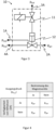
- FIG 3 14 illustrates an embodiment of an emergency brake valve system 10 of a brake control of part of a train according to the invention. It should be noted that in the present embodiment there are several such brake controls and thus emergency brake valve systems in a train.
- the emergency brake valve system according to the invention also has a pressure outlet 4A, at which the outlet pressure p Aus is made available.
- the emergency brake valve system according to the invention also contains a solenoid valve 11 and a piston valve 12 as well as three pressure inputs 1A, 2A and 3A. However, compared to the prior art, the inputs are subjected to reversed pressures.
- the static pressure p stat is present at the pressure inlet 1A and the regulated pressure p ger is present at the pressure inlet 2A.
- the static pressure p stat and the regulated pressure p ger at the respective pressure inputs have been interchanged.
- the solenoid valve 11 is configured in the emergency brake valve system according to the invention in such a way that it isolates the auxiliary pressure p ange from the piston valve 12 when energized.
- the piston valve 12 is therefore not actuated and the regulated pressure p ger is routed from the pressure inlet 2A to the pressure outlet 4A and is made available as the outlet pressure p Aus .
- the auxiliary pressure p o is routed to the piston valve 12, whereby the regulated pressure p ger is isolated and instead the static pressure p stat is routed to the pressure outlet 4A and made available as the outlet pressure p Aus .
- the regulated pressure p ger still represents the outlet pressure p Aus . It should be mentioned that the loss of the auxiliary pressure occurs only locally, i.e. in one of several brake controls of the train at the same time. since the auxiliary pressure is not made available to all brake systems via a central main air line. In this case, the train can be braked by the braking systems in the other wagons, which means that no emergency braking has to be initiated if the auxiliary pressure fails.
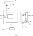
- FIG 5 shows part of a system architecture in which the emergency brake valve system 10 is integrated.
- the static pressure p stat is available through a pressure vessel 30 provided and passed to a pressure regulator 20 and via the pressure inputs 1A and 3A to the emergency brake valve system 10.
- the auxiliary pressure p help (in 3 ) is therefore with the static pressure p stat ( 3 ) identical.
- the regulated pressure p ger is made available as the outlet pressure p out and forwarded to the pressure regulator 20 .
- a control circuit 21 which controls the static pressure p stat from the pressure vessel 30 is located within the pressure regulator.
- both the pressure regulated by the control circuit 21 and the output pressure p Aus of the emergency brake valve can be forwarded to the brake cylinders 40 (not shown) as the brake pressure p br .
- the two pressures are superimposed and the respectively higher pressure is forwarded to the brake cylinder 40.
- an isolating valve 31 is provided on the pressure vessel 30, via which the supply of the brake system with static pressure p stat is prevented and the pressure in the lines between the isolating valve 31 and the pressure regulator 20 or the emergency brake valve 10 can be vented.
- the regulated pressure p ger can still be routed to the pressure outlet 4A by isolating and venting the static pressure p stat in the lines between the isolating cock 31 and the emergency brake valve 10 through the isolating cock 31.
- the piston valve 12 is actuated and the regulated pressure is present as the outlet pressure p Aus at the pressure outlet 4A.
- An adjustable brake pressure p br can thus be provided by the pressure regulator, via which controlled braking is possible, for example in the event of towing after emergency braking. This is realized by venting the static pressure and isolating the static pressure from the emergency brake valve so that due to the emergency brake valve according to the invention, the regulated pressure is available again as braking pressure.
Landscapes
- Engineering & Computer Science (AREA)
- Mechanical Engineering (AREA)
- Transportation (AREA)
- Physics & Mathematics (AREA)
- Electromagnetism (AREA)
- Fluid Mechanics (AREA)
- Valves And Accessory Devices For Braking Systems (AREA)
- Braking Systems And Boosters (AREA)
Applications Claiming Priority (2)
| Application Number | Priority Date | Filing Date | Title |
|---|---|---|---|
| DE102019113753.5A DE102019113753A1 (de) | 2019-05-23 | 2019-05-23 | Notbremsventilsystem für ein pneumatisches Bremssystem |
| PCT/EP2020/063460 WO2020234109A1 (de) | 2019-05-23 | 2020-05-14 | Notbremsventilsystem für ein pneumatisches bremssystem |
Publications (2)
| Publication Number | Publication Date |
|---|---|
| EP3972879A1 EP3972879A1 (de) | 2022-03-30 |
| EP3972879B1 true EP3972879B1 (de) | 2023-07-12 |
Family
ID=71016478
Family Applications (1)
| Application Number | Title | Priority Date | Filing Date |
|---|---|---|---|
| EP20730977.4A Active EP3972879B1 (de) | 2019-05-23 | 2020-05-14 | Notbremsventilsystem für ein pneumatisches bremssystem |
Country Status (11)
| Country | Link |
|---|---|
| US (1) | US20220227339A1 (pl) |
| EP (1) | EP3972879B1 (pl) |
| JP (1) | JP7469333B2 (pl) |
| KR (1) | KR102643561B1 (pl) |
| CN (1) | CN113853326B (pl) |
| AU (1) | AU2020280767B2 (pl) |
| BR (1) | BR112021021456A2 (pl) |
| DE (1) | DE102019113753A1 (pl) |
| ES (1) | ES2960042T3 (pl) |
| PL (1) | PL3972879T3 (pl) |
| WO (1) | WO2020234109A1 (pl) |
Families Citing this family (1)
| Publication number | Priority date | Publication date | Assignee | Title |
|---|---|---|---|---|
| EP4263304A1 (en) * | 2020-12-21 | 2023-10-25 | ZF CV Systems Europe BV | Electro-pneumatic hand brake system |
Family Cites Families (17)
| Publication number | Priority date | Publication date | Assignee | Title |
|---|---|---|---|---|
| KR930001020B1 (ko) * | 1987-06-16 | 1993-02-12 | 스미도모 덴기 고오교오 가부시기가이샤 | 액압 제어장치 및 이것을 사용한 브레이크장치 |
| JPH0367760A (ja) * | 1989-08-07 | 1991-03-22 | Sumitomo Electric Ind Ltd | ブレーキ装置 |
| DE3941408C1 (pl) * | 1989-12-15 | 1991-04-18 | Mercedes-Benz Aktiengesellschaft, 7000 Stuttgart, De | |
| DE19514603C2 (de) * | 1995-04-20 | 1997-04-03 | Daimler Benz Ag | Druckluft-Bremsanlage für ein Nutzfahrzeug |
| JP2003063366A (ja) * | 2001-08-30 | 2003-03-05 | Nabco Ltd | 鉄道車両用電気式応荷重弁 |
| DE102006018554B3 (de) * | 2006-04-21 | 2008-01-10 | Knorr-Bremse Systeme für Schienenfahrzeuge GmbH | Direkte Bremsvorrichtung eines Schienenfahrzeugs mit elektronischer Regelung und zusätzlichem pneumatischem Kreis |
| GB0723862D0 (en) * | 2007-12-06 | 2008-01-16 | Knorr Bremse Rail Sys Uk Ltd | Brake system |
| DE102008012700B3 (de) * | 2008-03-05 | 2009-06-04 | Knorr-Bremse Systeme für Schienenfahrzeuge GmbH | Elektropneumatische Bremseinrichtung mit lastkorrigierter Bremsdruckregelung |
| DE102009016986A1 (de) * | 2009-04-08 | 2010-10-14 | Knorr-Bremse Systeme für Schienenfahrzeuge GmbH | Verfahren und Einrichtung zur Bremskraftsteuerung |
| DE102010005091B4 (de) * | 2010-01-18 | 2013-08-08 | Siemens Aktiengesellschaft | Bremsanordnung eines Schienenfahrzeugs |
| JP5535893B2 (ja) | 2010-12-20 | 2014-07-02 | 三菱重工業株式会社 | ブレーキ装置及びこれを備えた軌道系車両 |
| DE102011110047A1 (de) * | 2011-08-12 | 2013-02-14 | Knorr-Bremse Systeme für Schienenfahrzeuge GmbH | Notbremseinrichtung für ein Schienenfahrzeug, Bremsanlage für ein Schienenfahrzeug sowie Schienenfahrzeug |
| EP3129265B1 (de) * | 2014-04-09 | 2018-04-04 | KNORR-BREMSE Systeme für Nutzfahrzeuge GmbH | Elektropneumatische bremssteuereinrichtung zur steuerung einer federspeicherbremse |
| DE102014013756C5 (de) * | 2014-09-22 | 2018-04-26 | Knorr-Bremse Systeme für Nutzfahrzeuge GmbH | Elektrische Ausrüstung eines Fahrzeugs mit einer wenigstens teilweise elektrischen Brems- und Lenkeinrichtung mit hoher Verfügbarkeit |
| DE102017120691A1 (de) * | 2017-09-07 | 2019-03-07 | Knorr-Bremse Systeme für Nutzfahrzeuge GmbH | Elektropneumatische Parkbremssteuereinrichtung |
| CN109318929B (zh) * | 2017-12-20 | 2020-03-06 | 中车长春轨道客车股份有限公司 | 一种列车备用制动控制系统及方法 |
| DE102018200487A1 (de) * | 2018-01-12 | 2019-07-18 | Knorr-Bremse Systeme für Schienenfahrzeuge GmbH | Vorrichtung und Verfahren zur Realisierung kontrollierter Reaktionen bei einer Systemstörung |
-
2019
- 2019-05-23 DE DE102019113753.5A patent/DE102019113753A1/de not_active Ceased
-
2020
- 2020-05-14 AU AU2020280767A patent/AU2020280767B2/en active Active
- 2020-05-14 US US17/613,843 patent/US20220227339A1/en active Pending
- 2020-05-14 CN CN202080037603.2A patent/CN113853326B/zh active Active
- 2020-05-14 EP EP20730977.4A patent/EP3972879B1/de active Active
- 2020-05-14 ES ES20730977T patent/ES2960042T3/es active Active
- 2020-05-14 KR KR1020217039090A patent/KR102643561B1/ko active Active
- 2020-05-14 PL PL20730977.4T patent/PL3972879T3/pl unknown
- 2020-05-14 JP JP2021569535A patent/JP7469333B2/ja active Active
- 2020-05-14 WO PCT/EP2020/063460 patent/WO2020234109A1/de not_active Ceased
- 2020-05-14 BR BR112021021456A patent/BR112021021456A2/pt unknown
Also Published As
| Publication number | Publication date |
|---|---|
| CN113853326A (zh) | 2021-12-28 |
| WO2020234109A1 (de) | 2020-11-26 |
| KR102643561B1 (ko) | 2024-03-05 |
| BR112021021456A2 (pt) | 2021-12-21 |
| JP7469333B2 (ja) | 2024-04-16 |
| PL3972879T3 (pl) | 2023-12-27 |
| AU2020280767B2 (en) | 2023-06-29 |
| JP2022534066A (ja) | 2022-07-27 |
| DE102019113753A1 (de) | 2020-11-26 |
| AU2020280767A1 (en) | 2021-12-09 |
| ES2960042T3 (es) | 2024-02-29 |
| KR20220003059A (ko) | 2022-01-07 |
| US20220227339A1 (en) | 2022-07-21 |
| EP3972879A1 (de) | 2022-03-30 |
| CN113853326B (zh) | 2024-09-13 |
Similar Documents
| Publication | Publication Date | Title |
|---|---|---|
| EP4396049B1 (de) | Verfahren zum betreiben eines elektropneumatischen bremssystems, ausfallsicherheitsventileinheit, elektropneumatisches bremssystem, fahrzeug | |
| EP3600992B1 (de) | Elektronisch steuerbares bremssystem sowie verfahren zum steuern des elektronisch steuerbaren bremssystems | |
| EP3755589B1 (de) | Elektropneumatische ausrüstung eines fahrzeugs | |
| EP4069559B1 (de) | Monostabil und fehlertolerant ausgelegte feststellbremsventilanordnung | |
| EP4061677B1 (de) | Ausfallsicherheitsventileinheit, elektronisch steuerbares pneumatisches bremssystem, verfahren zum betreiben eines bremssystems | |
| EP1847432B1 (de) | Direkte Bremsvorrichtung eines Schienenfahrzeugs mit elektronischer Regelung und zusätzlichem elektro-pneumatischen Kreis | |
| EP4396051B1 (de) | Elektropneumatisches bremssystem, fahrzeug, verfahren zum betreiben eines elektropneumatischen bremssystems mit einer notlöse-ventileinheit, verwendung einer notlöse-ventileinheit in einem elektropneumatischen bremssystem | |
| EP0447750A1 (de) | Bremsanlage mit wenigstens einem Bremskreis | |
| EP3583008B1 (de) | Verfahren und fahrzeugsteuergerät für ein autonomes fahrzeug und fahrzeug | |
| EP0207275B1 (de) | Hilfs- und Feststellbremse für Nutzfahrzeuge | |
| DE102016208966A1 (de) | Elektronisch druckregelbare Fahrzeugbremsanlage und Verfahren zur Steuerung einer elektronisch druckregelbaren Fahrzeugbremsanlage | |
| EP4126609B1 (de) | Elektronisch gesteuertes betriebsbremssystem mit auf der basis eines weiteren druckluftverbraucherkreises erzeugtem backup-steuerdruck | |
| EP0307579A1 (de) | Magnetgesteuerte Ventileinrichtung | |
| DE102021122501A1 (de) | Elektronisch steuerbares pneumatisches Bremssystem mit einer ausfallsicheren Bremsanwendung für einen autonomen Fahrbetrieb mit nur einem Wechselventil | |
| EP3286052B1 (de) | Parkbremseinrichtung für kraftfahrzeuge | |
| DE19848992A1 (de) | Bremssystem für ein Schienenfahrzeug | |
| DE3423944A1 (de) | Fahrzeugbremsanlage | |
| EP1646545B1 (de) | Bremsvorrichtung eines schienenfahrzeugs | |
| EP0234290B1 (de) | Elektropneumatische Bremseinrichtung für Fahrzeuge | |
| EP0345203A2 (de) | Elektronisch geregelte Druckmittel-Bremseinrichtung | |
| EP3972879B1 (de) | Notbremsventilsystem für ein pneumatisches bremssystem | |
| EP4341136B1 (de) | Elektropneumatische baueinheit mit integrierter ausfallsicherheitsventilanordnung für mehrfachfehler, elektronisch steuerbares pneumatisches bremssystem, sowie verfahren zum betreiben eines bremssystems | |
| EP3700790B1 (de) | Anordnung mit einem bremskrafterzeuger und verfahren zum betreiben eines bremskrafterzeugers | |
| EP3996962B1 (de) | Parkbremseinrichtung | |
| DE102023136454A1 (de) | Elektronisch steuerbares pneumatisches Bremssystem mit einem Umkehrrelaisventil zum Be- und Entlüften eines Federspeicherbremszylinders eines Fahrzeugs |
Legal Events
| Date | Code | Title | Description |
|---|---|---|---|
| STAA | Information on the status of an ep patent application or granted ep patent |
Free format text: STATUS: UNKNOWN |
|
| STAA | Information on the status of an ep patent application or granted ep patent |
Free format text: STATUS: THE INTERNATIONAL PUBLICATION HAS BEEN MADE |
|
| PUAI | Public reference made under article 153(3) epc to a published international application that has entered the european phase |
Free format text: ORIGINAL CODE: 0009012 |
|
| STAA | Information on the status of an ep patent application or granted ep patent |
Free format text: STATUS: REQUEST FOR EXAMINATION WAS MADE |
|
| 17P | Request for examination filed |
Effective date: 20211223 |
|
| AK | Designated contracting states |
Kind code of ref document: A1 Designated state(s): AL AT BE BG CH CY CZ DE DK EE ES FI FR GB GR HR HU IE IS IT LI LT LU LV MC MK MT NL NO PL PT RO RS SE SI SK SM TR |
|
| DAV | Request for validation of the european patent (deleted) | ||
| DAX | Request for extension of the european patent (deleted) | ||
| GRAP | Despatch of communication of intention to grant a patent |
Free format text: ORIGINAL CODE: EPIDOSNIGR1 |
|
| STAA | Information on the status of an ep patent application or granted ep patent |
Free format text: STATUS: GRANT OF PATENT IS INTENDED |
|
| INTG | Intention to grant announced |
Effective date: 20230125 |
|
| GRAS | Grant fee paid |
Free format text: ORIGINAL CODE: EPIDOSNIGR3 |
|
| GRAA | (expected) grant |
Free format text: ORIGINAL CODE: 0009210 |
|
| STAA | Information on the status of an ep patent application or granted ep patent |
Free format text: STATUS: THE PATENT HAS BEEN GRANTED |
|
| AK | Designated contracting states |
Kind code of ref document: B1 Designated state(s): AL AT BE BG CH CY CZ DE DK EE ES FI FR GB GR HR HU IE IS IT LI LT LU LV MC MK MT NL NO PL PT RO RS SE SI SK SM TR |
|
| REG | Reference to a national code |
Ref country code: CH Ref legal event code: EP |
|
| REG | Reference to a national code |
Ref country code: DE Ref legal event code: R096 Ref document number: 502020004170 Country of ref document: DE |
|
| REG | Reference to a national code |
Ref country code: IE Ref legal event code: FG4D Free format text: LANGUAGE OF EP DOCUMENT: GERMAN |
|
| REG | Reference to a national code |
Ref country code: SE Ref legal event code: TRGR |
|
| REG | Reference to a national code |
Ref country code: LT Ref legal event code: MG9D |
|
| REG | Reference to a national code |
Ref country code: NL Ref legal event code: MP Effective date: 20230712 |
|
| PG25 | Lapsed in a contracting state [announced via postgrant information from national office to epo] |
Ref country code: NL Free format text: LAPSE BECAUSE OF FAILURE TO SUBMIT A TRANSLATION OF THE DESCRIPTION OR TO PAY THE FEE WITHIN THE PRESCRIBED TIME-LIMIT Effective date: 20230712 |
|
| PG25 | Lapsed in a contracting state [announced via postgrant information from national office to epo] |
Ref country code: GR Free format text: LAPSE BECAUSE OF FAILURE TO SUBMIT A TRANSLATION OF THE DESCRIPTION OR TO PAY THE FEE WITHIN THE PRESCRIBED TIME-LIMIT Effective date: 20231013 |
|
| PG25 | Lapsed in a contracting state [announced via postgrant information from national office to epo] |
Ref country code: IS Free format text: LAPSE BECAUSE OF FAILURE TO SUBMIT A TRANSLATION OF THE DESCRIPTION OR TO PAY THE FEE WITHIN THE PRESCRIBED TIME-LIMIT Effective date: 20231112 |
|
| PG25 | Lapsed in a contracting state [announced via postgrant information from national office to epo] |
Ref country code: RS Free format text: LAPSE BECAUSE OF FAILURE TO SUBMIT A TRANSLATION OF THE DESCRIPTION OR TO PAY THE FEE WITHIN THE PRESCRIBED TIME-LIMIT Effective date: 20230712 Ref country code: PT Free format text: LAPSE BECAUSE OF FAILURE TO SUBMIT A TRANSLATION OF THE DESCRIPTION OR TO PAY THE FEE WITHIN THE PRESCRIBED TIME-LIMIT Effective date: 20231113 Ref country code: NO Free format text: LAPSE BECAUSE OF FAILURE TO SUBMIT A TRANSLATION OF THE DESCRIPTION OR TO PAY THE FEE WITHIN THE PRESCRIBED TIME-LIMIT Effective date: 20231012 Ref country code: LV Free format text: LAPSE BECAUSE OF FAILURE TO SUBMIT A TRANSLATION OF THE DESCRIPTION OR TO PAY THE FEE WITHIN THE PRESCRIBED TIME-LIMIT Effective date: 20230712 Ref country code: LT Free format text: LAPSE BECAUSE OF FAILURE TO SUBMIT A TRANSLATION OF THE DESCRIPTION OR TO PAY THE FEE WITHIN THE PRESCRIBED TIME-LIMIT Effective date: 20230712 Ref country code: IS Free format text: LAPSE BECAUSE OF FAILURE TO SUBMIT A TRANSLATION OF THE DESCRIPTION OR TO PAY THE FEE WITHIN THE PRESCRIBED TIME-LIMIT Effective date: 20231112 Ref country code: HR Free format text: LAPSE BECAUSE OF FAILURE TO SUBMIT A TRANSLATION OF THE DESCRIPTION OR TO PAY THE FEE WITHIN THE PRESCRIBED TIME-LIMIT Effective date: 20230712 Ref country code: GR Free format text: LAPSE BECAUSE OF FAILURE TO SUBMIT A TRANSLATION OF THE DESCRIPTION OR TO PAY THE FEE WITHIN THE PRESCRIBED TIME-LIMIT Effective date: 20231013 Ref country code: FI Free format text: LAPSE BECAUSE OF FAILURE TO SUBMIT A TRANSLATION OF THE DESCRIPTION OR TO PAY THE FEE WITHIN THE PRESCRIBED TIME-LIMIT Effective date: 20230712 |
|
| P01 | Opt-out of the competence of the unified patent court (upc) registered |
Effective date: 20240123 |
|
| REG | Reference to a national code |
Ref country code: ES Ref legal event code: FG2A Ref document number: 2960042 Country of ref document: ES Kind code of ref document: T3 Effective date: 20240229 |
|
| REG | Reference to a national code |
Ref country code: DE Ref legal event code: R097 Ref document number: 502020004170 Country of ref document: DE |
|
| PG25 | Lapsed in a contracting state [announced via postgrant information from national office to epo] |
Ref country code: SM Free format text: LAPSE BECAUSE OF FAILURE TO SUBMIT A TRANSLATION OF THE DESCRIPTION OR TO PAY THE FEE WITHIN THE PRESCRIBED TIME-LIMIT Effective date: 20230712 Ref country code: RO Free format text: LAPSE BECAUSE OF FAILURE TO SUBMIT A TRANSLATION OF THE DESCRIPTION OR TO PAY THE FEE WITHIN THE PRESCRIBED TIME-LIMIT Effective date: 20230712 Ref country code: EE Free format text: LAPSE BECAUSE OF FAILURE TO SUBMIT A TRANSLATION OF THE DESCRIPTION OR TO PAY THE FEE WITHIN THE PRESCRIBED TIME-LIMIT Effective date: 20230712 Ref country code: DK Free format text: LAPSE BECAUSE OF FAILURE TO SUBMIT A TRANSLATION OF THE DESCRIPTION OR TO PAY THE FEE WITHIN THE PRESCRIBED TIME-LIMIT Effective date: 20230712 Ref country code: CZ Free format text: LAPSE BECAUSE OF FAILURE TO SUBMIT A TRANSLATION OF THE DESCRIPTION OR TO PAY THE FEE WITHIN THE PRESCRIBED TIME-LIMIT Effective date: 20230712 Ref country code: SK Free format text: LAPSE BECAUSE OF FAILURE TO SUBMIT A TRANSLATION OF THE DESCRIPTION OR TO PAY THE FEE WITHIN THE PRESCRIBED TIME-LIMIT Effective date: 20230712 |
|
| PLBE | No opposition filed within time limit |
Free format text: ORIGINAL CODE: 0009261 |
|
| STAA | Information on the status of an ep patent application or granted ep patent |
Free format text: STATUS: NO OPPOSITION FILED WITHIN TIME LIMIT |
|
| 26N | No opposition filed |
Effective date: 20240415 |
|
| PG25 | Lapsed in a contracting state [announced via postgrant information from national office to epo] |
Ref country code: SI Free format text: LAPSE BECAUSE OF FAILURE TO SUBMIT A TRANSLATION OF THE DESCRIPTION OR TO PAY THE FEE WITHIN THE PRESCRIBED TIME-LIMIT Effective date: 20230712 |
|
| PG25 | Lapsed in a contracting state [announced via postgrant information from national office to epo] |
Ref country code: BG Free format text: LAPSE BECAUSE OF FAILURE TO SUBMIT A TRANSLATION OF THE DESCRIPTION OR TO PAY THE FEE WITHIN THE PRESCRIBED TIME-LIMIT Effective date: 20230712 |
|
| PG25 | Lapsed in a contracting state [announced via postgrant information from national office to epo] |
Ref country code: BG Free format text: LAPSE BECAUSE OF FAILURE TO SUBMIT A TRANSLATION OF THE DESCRIPTION OR TO PAY THE FEE WITHIN THE PRESCRIBED TIME-LIMIT Effective date: 20230712 |
|
| PG25 | Lapsed in a contracting state [announced via postgrant information from national office to epo] |
Ref country code: MC Free format text: LAPSE BECAUSE OF FAILURE TO SUBMIT A TRANSLATION OF THE DESCRIPTION OR TO PAY THE FEE WITHIN THE PRESCRIBED TIME-LIMIT Effective date: 20230712 |
|
| PG25 | Lapsed in a contracting state [announced via postgrant information from national office to epo] |
Ref country code: LU Free format text: LAPSE BECAUSE OF NON-PAYMENT OF DUE FEES Effective date: 20240514 |
|
| PG25 | Lapsed in a contracting state [announced via postgrant information from national office to epo] |
Ref country code: MC Free format text: LAPSE BECAUSE OF FAILURE TO SUBMIT A TRANSLATION OF THE DESCRIPTION OR TO PAY THE FEE WITHIN THE PRESCRIBED TIME-LIMIT Effective date: 20230712 Ref country code: LU Free format text: LAPSE BECAUSE OF NON-PAYMENT OF DUE FEES Effective date: 20240514 |
|
| REG | Reference to a national code |
Ref country code: BE Ref legal event code: MM Effective date: 20240531 |
|
| PG25 | Lapsed in a contracting state [announced via postgrant information from national office to epo] |
Ref country code: IE Free format text: LAPSE BECAUSE OF NON-PAYMENT OF DUE FEES Effective date: 20240514 |
|
| PG25 | Lapsed in a contracting state [announced via postgrant information from national office to epo] |
Ref country code: BE Free format text: LAPSE BECAUSE OF NON-PAYMENT OF DUE FEES Effective date: 20240531 |
|
| PGFP | Annual fee paid to national office [announced via postgrant information from national office to epo] |
Ref country code: PL Payment date: 20250505 Year of fee payment: 6 Ref country code: DE Payment date: 20250528 Year of fee payment: 6 |
|
| PGFP | Annual fee paid to national office [announced via postgrant information from national office to epo] |
Ref country code: GB Payment date: 20250526 Year of fee payment: 6 Ref country code: ES Payment date: 20250612 Year of fee payment: 6 |
|
| PGFP | Annual fee paid to national office [announced via postgrant information from national office to epo] |
Ref country code: IT Payment date: 20250522 Year of fee payment: 6 |
|
| PGFP | Annual fee paid to national office [announced via postgrant information from national office to epo] |
Ref country code: FR Payment date: 20250526 Year of fee payment: 6 |
|
| PGFP | Annual fee paid to national office [announced via postgrant information from national office to epo] |
Ref country code: CH Payment date: 20250601 Year of fee payment: 6 |
|
| PGFP | Annual fee paid to national office [announced via postgrant information from national office to epo] |
Ref country code: AT Payment date: 20250721 Year of fee payment: 5 |
|
| PGFP | Annual fee paid to national office [announced via postgrant information from national office to epo] |
Ref country code: SE Payment date: 20250526 Year of fee payment: 6 |
|
| PG25 | Lapsed in a contracting state [announced via postgrant information from national office to epo] |
Ref country code: CY Free format text: LAPSE BECAUSE OF FAILURE TO SUBMIT A TRANSLATION OF THE DESCRIPTION OR TO PAY THE FEE WITHIN THE PRESCRIBED TIME-LIMIT; INVALID AB INITIO Effective date: 20200514 |
|
| PG25 | Lapsed in a contracting state [announced via postgrant information from national office to epo] |
Ref country code: HU Free format text: LAPSE BECAUSE OF FAILURE TO SUBMIT A TRANSLATION OF THE DESCRIPTION OR TO PAY THE FEE WITHIN THE PRESCRIBED TIME-LIMIT; INVALID AB INITIO Effective date: 20200514 |