EP3972876B1 - Energieverwaltungssystem - Google Patents
Energieverwaltungssystem Download PDFInfo
- Publication number
- EP3972876B1 EP3972876B1 EP20731765.2A EP20731765A EP3972876B1 EP 3972876 B1 EP3972876 B1 EP 3972876B1 EP 20731765 A EP20731765 A EP 20731765A EP 3972876 B1 EP3972876 B1 EP 3972876B1
- Authority
- EP
- European Patent Office
- Prior art keywords
- mobility device
- tie
- wheeled mobility
- impact
- bumper
- Prior art date
- Legal status (The legal status is an assumption and is not a legal conclusion. Google has not performed a legal analysis and makes no representation as to the accuracy of the status listed.)
- Active
Links
Images


Classifications
-
- B—PERFORMING OPERATIONS; TRANSPORTING
- B60—VEHICLES IN GENERAL
- B60R—VEHICLES, VEHICLE FITTINGS, OR VEHICLE PARTS, NOT OTHERWISE PROVIDED FOR
- B60R21/00—Arrangements or fittings on vehicles for protecting or preventing injuries to occupants or pedestrians in case of accidents or other traffic risks
- B60R21/01—Electrical circuits for triggering passive safety arrangements, e.g. airbags, safety belt tighteners, in case of vehicle accidents or impending vehicle accidents
- B60R21/015—Electrical circuits for triggering passive safety arrangements, e.g. airbags, safety belt tighteners, in case of vehicle accidents or impending vehicle accidents including means for detecting the presence or position of passengers, passenger seats or child seats, and the related safety parameters therefor, e.g. speed or timing of airbag inflation in relation to occupant position or seat belt use
- B60R21/01512—Passenger detection systems
- B60R21/01544—Passenger detection systems detecting seat belt parameters, e.g. length, tension or height-adjustment
-
- A—HUMAN NECESSITIES
- A61—MEDICAL OR VETERINARY SCIENCE; HYGIENE
- A61G—TRANSPORT, PERSONAL CONVEYANCES, OR ACCOMMODATION SPECIALLY ADAPTED FOR PATIENTS OR DISABLED PERSONS; OPERATING TABLES OR CHAIRS; CHAIRS FOR DENTISTRY; FUNERAL DEVICES
- A61G3/00—Ambulance aspects of vehicles; Vehicles with special provisions for transporting patients or disabled persons, or their personal conveyances, e.g. for facilitating access of, or for loading, wheelchairs
- A61G3/006—Means for reducing the influence of acceleration on patients, e.g. suspension systems of platforms
-
- A—HUMAN NECESSITIES
- A61—MEDICAL OR VETERINARY SCIENCE; HYGIENE
- A61G—TRANSPORT, PERSONAL CONVEYANCES, OR ACCOMMODATION SPECIALLY ADAPTED FOR PATIENTS OR DISABLED PERSONS; OPERATING TABLES OR CHAIRS; CHAIRS FOR DENTISTRY; FUNERAL DEVICES
- A61G3/00—Ambulance aspects of vehicles; Vehicles with special provisions for transporting patients or disabled persons, or their personal conveyances, e.g. for facilitating access of, or for loading, wheelchairs
- A61G3/08—Accommodating or securing wheelchairs or stretchers
- A61G3/0808—Accommodating or securing wheelchairs
-
- B—PERFORMING OPERATIONS; TRANSPORTING
- B60—VEHICLES IN GENERAL
- B60R—VEHICLES, VEHICLE FITTINGS, OR VEHICLE PARTS, NOT OTHERWISE PROVIDED FOR
- B60R21/00—Arrangements or fittings on vehicles for protecting or preventing injuries to occupants or pedestrians in case of accidents or other traffic risks
- B60R21/01—Electrical circuits for triggering passive safety arrangements, e.g. airbags, safety belt tighteners, in case of vehicle accidents or impending vehicle accidents
- B60R21/013—Electrical circuits for triggering passive safety arrangements, e.g. airbags, safety belt tighteners, in case of vehicle accidents or impending vehicle accidents including means for detecting collisions, impending collisions or roll-over
- B60R21/0132—Electrical circuits for triggering passive safety arrangements, e.g. airbags, safety belt tighteners, in case of vehicle accidents or impending vehicle accidents including means for detecting collisions, impending collisions or roll-over responsive to vehicle motion parameters, e.g. to vehicle longitudinal or transversal deceleration or speed value
-
- B—PERFORMING OPERATIONS; TRANSPORTING
- B60—VEHICLES IN GENERAL
- B60R—VEHICLES, VEHICLE FITTINGS, OR VEHICLE PARTS, NOT OTHERWISE PROVIDED FOR
- B60R21/00—Arrangements or fittings on vehicles for protecting or preventing injuries to occupants or pedestrians in case of accidents or other traffic risks
- B60R21/02—Occupant safety arrangements or fittings, e.g. crash pads
- B60R21/055—Padded or energy-absorbing fittings, e.g. seat belt anchors
-
- B—PERFORMING OPERATIONS; TRANSPORTING
- B60—VEHICLES IN GENERAL
- B60R—VEHICLES, VEHICLE FITTINGS, OR VEHICLE PARTS, NOT OTHERWISE PROVIDED FOR
- B60R21/00—Arrangements or fittings on vehicles for protecting or preventing injuries to occupants or pedestrians in case of accidents or other traffic risks
- B60R21/02—Occupant safety arrangements or fittings, e.g. crash pads
- B60R21/16—Inflatable occupant restraints or confinements designed to inflate upon impact or impending impact, e.g. air bags
-
- G—PHYSICS
- G06—COMPUTING OR CALCULATING; COUNTING
- G06V—IMAGE OR VIDEO RECOGNITION OR UNDERSTANDING
- G06V20/00—Scenes; Scene-specific elements
- G06V20/50—Context or environment of the image
- G06V20/59—Context or environment of the image inside of a vehicle, e.g. relating to seat occupancy, driver state or inner lighting conditions
-
- A—HUMAN NECESSITIES
- A61—MEDICAL OR VETERINARY SCIENCE; HYGIENE
- A61G—TRANSPORT, PERSONAL CONVEYANCES, OR ACCOMMODATION SPECIALLY ADAPTED FOR PATIENTS OR DISABLED PERSONS; OPERATING TABLES OR CHAIRS; CHAIRS FOR DENTISTRY; FUNERAL DEVICES
- A61G2203/00—General characteristics of devices
- A61G2203/70—General characteristics of devices with special adaptations, e.g. for safety or comfort
- A61G2203/72—General characteristics of devices with special adaptations, e.g. for safety or comfort for collision prevention
- A61G2203/723—Impact absorbing means, e.g. bumpers or airbags
-
- B—PERFORMING OPERATIONS; TRANSPORTING
- B60—VEHICLES IN GENERAL
- B60R—VEHICLES, VEHICLE FITTINGS, OR VEHICLE PARTS, NOT OTHERWISE PROVIDED FOR
- B60R21/00—Arrangements or fittings on vehicles for protecting or preventing injuries to occupants or pedestrians in case of accidents or other traffic risks
- B60R2021/0002—Type of accident
- B60R2021/0004—Frontal collision
-
- B—PERFORMING OPERATIONS; TRANSPORTING
- B60—VEHICLES IN GENERAL
- B60R—VEHICLES, VEHICLE FITTINGS, OR VEHICLE PARTS, NOT OTHERWISE PROVIDED FOR
- B60R21/00—Arrangements or fittings on vehicles for protecting or preventing injuries to occupants or pedestrians in case of accidents or other traffic risks
- B60R2021/0002—Type of accident
- B60R2021/0006—Lateral collision
-
- B—PERFORMING OPERATIONS; TRANSPORTING
- B60—VEHICLES IN GENERAL
- B60R—VEHICLES, VEHICLE FITTINGS, OR VEHICLE PARTS, NOT OTHERWISE PROVIDED FOR
- B60R21/00—Arrangements or fittings on vehicles for protecting or preventing injuries to occupants or pedestrians in case of accidents or other traffic risks
- B60R2021/0002—Type of accident
- B60R2021/0018—Roll-over
-
- B—PERFORMING OPERATIONS; TRANSPORTING
- B60—VEHICLES IN GENERAL
- B60R—VEHICLES, VEHICLE FITTINGS, OR VEHICLE PARTS, NOT OTHERWISE PROVIDED FOR
- B60R21/00—Arrangements or fittings on vehicles for protecting or preventing injuries to occupants or pedestrians in case of accidents or other traffic risks
- B60R2021/003—Arrangements or fittings on vehicles for protecting or preventing injuries to occupants or pedestrians in case of accidents or other traffic risks characterised by occupant or pedestian
- B60R2021/0039—Body parts of the occupant or pedestrian affected by the accident
- B60R2021/0048—Head
-
- B—PERFORMING OPERATIONS; TRANSPORTING
- B60—VEHICLES IN GENERAL
- B60R—VEHICLES, VEHICLE FITTINGS, OR VEHICLE PARTS, NOT OTHERWISE PROVIDED FOR
- B60R21/00—Arrangements or fittings on vehicles for protecting or preventing injuries to occupants or pedestrians in case of accidents or other traffic risks
- B60R2021/003—Arrangements or fittings on vehicles for protecting or preventing injuries to occupants or pedestrians in case of accidents or other traffic risks characterised by occupant or pedestian
- B60R2021/006—Type of passenger
-
- B—PERFORMING OPERATIONS; TRANSPORTING
- B60—VEHICLES IN GENERAL
- B60R—VEHICLES, VEHICLE FITTINGS, OR VEHICLE PARTS, NOT OTHERWISE PROVIDED FOR
- B60R21/00—Arrangements or fittings on vehicles for protecting or preventing injuries to occupants or pedestrians in case of accidents or other traffic risks
- B60R21/01—Electrical circuits for triggering passive safety arrangements, e.g. airbags, safety belt tighteners, in case of vehicle accidents or impending vehicle accidents
- B60R2021/01204—Actuation parameters of safety arrangents
- B60R2021/01211—Expansion of air bags
- B60R2021/01231—Expansion of air bags control of expansion timing or sequence
-
- B—PERFORMING OPERATIONS; TRANSPORTING
- B60—VEHICLES IN GENERAL
- B60Y—INDEXING SCHEME RELATING TO ASPECTS CROSS-CUTTING VEHICLE TECHNOLOGY
- B60Y2200/00—Type of vehicle
- B60Y2200/80—Other vehicles not covered by groups B60Y2200/10 - B60Y2200/60
- B60Y2200/84—Wheelchairs
-
- B—PERFORMING OPERATIONS; TRANSPORTING
- B60—VEHICLES IN GENERAL
- B60Y—INDEXING SCHEME RELATING TO ASPECTS CROSS-CUTTING VEHICLE TECHNOLOGY
- B60Y2400/00—Special features of vehicle units
- B60Y2400/30—Sensors
Definitions
- the embodiments described and claimed herein relate generally to securement systems for mobility devices, and more particularly to a comprehensive energy management system for controlling excursion of a wheeled mobility device and its occupant during various adverse driving scenarios and modes, such as vehicle impacts and aggressive maneuvers.
- the seat for an ambulatory passenger is integral with the vehicle and can be considered to be fixed rigidly in place to the vehicle during adverse driving conditions.
- the shape of the seat is designed for crash support of the occupant, and the seat is designed to not move during a crash. In that respect, seats for ambulatory passengers will not contribute to additional passenger movement nor will it interfere with the forward excursions of the occupant during impact.
- seats for ambulatory passengers will support rear excursions of the occupant ( i.e. , will block and load limits the ambulatory passenger's rear movement) and will significantly reduce the associated rear excursion. Therefore, in the current state of technology for ambulatory passengers, the seating system does not exacerbate excursions and only supports the passenger during excursions.
- a wheeled mobility device where the passenger's seating system is not integral to the vehicle. Rather, the wheeled mobility device is temporarily fixed to the vehicle, in some cases with securements systems that can be "elastic" in nature and can give and stretch and be significantly affected by an adverse driving condition.
- a typical system will include tie-downs formed of webbing that not only will stretch and allow movement of the wheeled mobility device during transit, but also may unspool ( i.e., even when the spool is locked, loosely wrapped webbing can spool out).
- both the wheeled mobility device (i.e., the seat) and the passenger commence to move forward ( i.e.
- both the mobility device and the passenger commence to move rearward (i.e. , rearward excursion), again, at different times and different rates.
- the mobility device and the passenger can also both experience side excursions in the case of side impacts, roll overs, or in front/rear impacts that involve rotational forces ( i.e., mobility device and passenger can move along any axis, including vertical and horizontal axes), again, at different times and different rates.
- forward refers to the "forward" direction of the vehicle, not the direction of the wheeled mobility device which can be installed in forward-facing, rear-facing, and side-facing orientations.
- Forward, rearward, sideward, and vertical excursions of the wheeled mobility device are limited by tie-downs, bumpers and/or other securement members, whereas the excursion of the passenger is separately limited by the combination of the occupant restraints and the chair ( e.g.
- the occupant restraints limit movement of the passenger in the case of a forward excursion
- the seat back limits movement of the passenger in the case of a rear excursion
- the seat bottom limits movement of the passenger in the case of a downward excursion
- the occupant restraints limit movement of the passenger in the case of an upward excursion
- occupant restraints and armrests limit movement of the passenger in the case of a side excursion
- both objects i.e. , the passenger and the chair
- the wheeled mobility device can compress the occupant against the occupant restraints (thereby exposing the occupant restraints to the combined weight of the occupant and the chair) and/or exacerbate or reduce the occupant's excursion ( e . g ., in a forward facing system, the wheeled mobility device can propel the occupant in a forward excursion and slow down the occupant a rearward excursion).
- the occupant can similarly impact the wheeled mobility device's excursion ( e . g ., the occupant can push the wheeled mobility device and expose the tie-downs to the combined weight of the chair and the occupant).
- the fastening or tie-down methods for an ambulatory seat and a wheelchair are drastically different.
- the method of securement does not contribute to any additional forward excursion of the seat.
- the bolts do not allow the seat to move in impact and do not exacerbate a rebound event.
- the method of securement usually allows for and exacerbates excursions.
- webbing stretch along with spooling-out can contribute to an increase in excursions (i.e.
- the energy stored in the webbing due to stretching can be released at the end of an initial excursion and exacerbate a rebound event ( i.e. , a secondary excursion in an opposite direction) and cause oscillations of both the wheeled mobility device and passenger.
- a rebound event i.e. , a secondary excursion in an opposite direction
- certain retractors can experience undesirable slack in its webbing, whereby the retractor will be unable to prevent or minimize a rebound event.
- the separate securement of the occupant and wheeled mobility device allows for independent and dynamic movement (or reactions) and interactions for both the occupant and the chair. Because they do not take into account a moving seat, existing vehicle safety systems for ambulatory passengers are inadequate and cannot be utilized to secure a wheeled mobility device and its occupant in a vehicle. Existing vehicle safety systems also do not take into account the separate nature of the secondary and tertiary events ( i.e., occurring at different times) for the seat and occupant, such as rebounds, oscillations, or whiplash.
- a system may be configured to use tensioning and/or load-limiting technology in a way that takes into account the excursion of the wheelchair and the resultant secondary excursion (i.e. , whiplash/rebound) or tertiary movements (oscillations) of that wheeled mobility device ( i.e. , after whiplash).
- tensioning and/or load-limiting technology in a way that takes into account the excursion of the wheelchair and the resultant secondary excursion (i.e. , whiplash/rebound) or tertiary movements (oscillations) of that wheeled mobility device (i.e. , after whiplash).
- the wheeled mobility device and passenger will exhibit independent excursions and may dynamically interact in other adverse driving conditions, such as impacts on other sides of the vehicle, angled impacts, offset impacts, rollovers, heavy braking, sharp turns, and long duration turns. Accordingly, there is a need for an energy management system that can interact with various safety systems to control the energy associated with the various excursions of the wheeled mobility device and passenger during such adverse driving conditions.
- the computing device 110 may also communicate with other computing devices, computers, workstations, etc. or networks thereof through a communications adapter 150, such as a telephone, cable, or wireless modem, ISDN Adapter, DSL adapter, Local Area Network (LAN) adapter, or other communications channel.
- a communications adapter 150 such as a telephone, cable, or wireless modem, ISDN Adapter, DSL adapter, Local Area Network (LAN) adapter, or other communications channel.
- the computing device 110 may use multiple communication adapters for making the necessary communication connections (e . g ., a telephone modem card and a LAN adapter).
- the computing device 110 may be associated with other computing devices in a LAN or WAN. All these configurations, as well as the appropriate communications hardware and software, are known in the art.
- the computing device 110 provides the facility for running software, such as Operating System software and Application software. Note that such software executes tasks and may communicate with various software components on this and other computing devices.
- software such as Operating System software and Application software.
- computer programs such as that described herein are typically distributed as part of a computer program product that has a computer useable media or medium containing or storing the program code.
- Such media may include a computer memory (RAM and/or ROM), a diskette, a tape, a compact disc, a DVD, an integrated circuit, a programmable logic array (PLA), a remote transmission over a communications circuit, a remote transmission over a wireless network such as a cellular network, or any other medium useable by computers with or without proper adapter interfaces
- the computing device 110 may be located onboard a wheeled mobility device securement system, or may be located remotely in the vehicle or elsewhere.
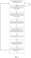
- the computing device 110 may be programmed to or includes a computer program product that may be configured to: monitor or ascertain various characteristics of one or more of the vehicle, the wheeled mobility device securement system (including but not limited to the types of securement systems described herein), the wheeled mobility device, and the passenger; determine or approximate or ascertain the timing for various phases of an adverse driving condition, select an appropriate safety system or systems to trigger in any given phase; and trigger the appropriate safety system(s) at the ideal time(s).
- the processor 120 may be configured to communicate with the vehicle operator and/or the wheelchair passenger through one or more optional interface panels 190.
- the panels 190 may contain command switches or buttons that produce signals, as well as indicator lights, audible alarms, and voice, with optional text or full graphic displays with touch-sensing capabilities.
- the panels 190 may be a wall-mounted unit, a wired or wireless remote control, or even an application running on a tablet or mobile device, such as an iPhone.
- the computing device 110 may be configured to receive signals from the vehicle 195 representative of the status and/or various dynamic conditions of the vehicle, including but not limited to: the location, direction of travel, velocity, and acceleration/deceleration of the vehicle along one or more of the x-, y-, and z-axes; the time an impact occurs; the magnitude, direction and/or type of the impact; the location, distance, direction, velocity, and/or approaching velocity of other vehicles or obstructions; the probability of a collision occurring; estimated time of collision; vehicle stopped; vehicle neutralized, in gear, out of gear, in park, powered down, etc.; vehicle brake applied; vehicle accelerator applied; steering wheel position; vehicle door status; and any other information that may be accessible from the vehicle systems.
- any such information that can be obtained from the vehicle may also be ascertained or calculated independently by the computing device 110 and associated sensors and other technology, including accelerometers, GPS receivers, sonar, and the like.
- the computing device 110 may be configured to communicate with external sources 160 to receive information concerning the vehicle.
- a video-based analytic system could be used to confirm which tie-downs and occupant restraints are being used, and to detect the length of webbing/strap that has been withdrawn from the retractor and the vertical and horizontal angles of the webbing/strap.
- sensors e . g ., proximity sensors, motor current sensors, etc.
- sensors may be used to detect the position of bumper and the amount of force being exerted on the wheeled mobility device by the bumper.
- sensors e . g ., proximity sensors, motor current sensors, etc.
- Those sensors or devices 160 may include one or more of a floor pressure sensor, proximity sensors, accelerometers mounted to the passenger or the occupant restraint, an array of IR beams, a WMD-mounted or occupant-retained RFID tag, WMD-mounted or occupant-retained QR code, and/or a camera and image recognition software (i.e., a video-based analytic system). See, for example, the various sensors disclosed in U.S. Provisional Patent Application No. 62/825,325, filed on March 28, 2019 , which is incorporated herein by reference.
- the computing device 110 could additionally or alternatively ascertain that an adverse driving condition has occurred by monitoring one or more signals concerning the status and/or dynamic characteristics of the vehicle, the securement system, the wheeled mobility device, and/or the passenger.
- the computing device 110 may receive a signal indicative of the vehicle acceleration, and subsequently determine if that acceleration (for example, a spike in acceleration and/or the direction and/or the magnitude) is indicative of an adverse driving condition.
- the computing device 110 may receive input indicative of the tension on the wheelchair tie-downs and/or occupant restraints, and subsequently determine if the tension seen by the respective device (for example, a spike in tension and/or the magnitude) is indicative of an adverse driving condition.
- the computing device 110 could additionally or alternatively ascertain one or more characteristics of the adverse driving condition by monitoring one or more signals concerning the status and/or dynamic characteristics of the vehicle, the securement system, the wheeled mobility device, and/or the passenger (i.e., how any one or more of the vehicle, securement system, wheeled mobility device, and passenger are responding to the adverse driving event).
- This information could be used directly as indicative of the characteristic of the adverse driving condition.
- the computing device could use such information as a basis for characterizing the nature and magnitude of the adverse driving event for use in one or more of the following steps.
- the computing device 110 could skip to the fourth step 240 through the sixth step 260, or proceed directly to the third step 230.
- the computing device 110 may be programmed to ascertain one or more characteristics of the wheeled mobility device's dynamic response to the adverse driving condition.
- the computing device 110 may receive inputs that are indicative of the actual dynamic response of the wheeled mobility device. Additionally or alternatively, the computing device 110 may ascertain computationally or through table look-ups the anticipated dynamic response of the wheeled mobility device using the characteristic(s) of adverse driving condition from the second step 220 ( e.g. , the dynamic characteristics of the vehicle) as an input.
- the computing device 110 could skip to the fifth step 250 or the sixth step 260, or proceed directly to the fourth step 240.
- the computing device 110 may be programmed to ascertain one or more characteristics of the passenger's dynamic response to the adverse driving condition.
- the computing device 110 may receive inputs that are indicative of the actual dynamic response of the passenger. Additionally or alternatively, the computing device 110 may ascertain computationally or through table look-ups the anticipated dynamic response of the passenger using the characteristic(s) of adverse driving condition from the second step 220 ( e.g., the dynamic characteristics of the vehicle) as an input.
- the computing device will ascertain which safety devices are appropriate to use under the circumstances, using the information ascertained from one or more of the first through fifth steps 210, 220, 230, 240, 250 as an input. For example, during a forward collision or heavy braking event, it may be desirable to trigger a safety device that draws up slack in the forward restraints.
- the computing device 110 could be programmed to ascertain or calculate the rebound times based on one or more of the direction of vehicle travel, the orientation of the passenger (i.e., rearward or forward or side facing), the direction of crash ( i . e ., forward impact, side impact, rear impact, angled impact, offset impact, rollover, etc.), the severity of the crash.
- the computing device 110 could also rely on the maximum excursions allowed within the vehicle or by legislation (i.e., is programmed to know the vehicle environment or was preprogrammed with the wheelchair compartment dimensions, etc.), visual means of seeing the position and/or change in velocity of the wheeled mobility device and occupant ( i.e., camera detects forward movement into multiple zones, once the next 'zone' is not crossed this is the maximum forward excursion), or sensors ( e .
- the vehicle e.g., accelerometers
- the computing device 110 will trigger the appropriate safety device at the appropriate time.
- the computing device 110 may be programmed to repeat any one or more of the first through eighth steps 210, 220, 230, 240, 250, 260, 270, 280 to address subsequent or secondary adverse driving conditions or rebounds and oscillations. In some instances, it may be desirable to activate the same safety device more than once, which can be accomplished through the use of a multi-use safety device, or multiple single-use safety devices.
- the two front-side tie-downs 320, 325 are ideally spaced apart a distance equal to or wider than the width of the wheeled mobility device 310, whereby the straps are angled toward each other as they extend from the vehicle attachment points to the wheeled mobility device attachment points, as shown.
- This configuration increases the chance that the front-side straps will have a direct path from the vehicle attachment points to the wheeled mobility device attachment points, without significantly interfering with the passenger's legs or feet.
- the two rear-side tie downs 330, 335 are ideally spaced apart a distance equal to or narrower than the width of the wheeled mobility device 310, whereby the straps are angled away from each other as they extend from the vehicle attachment point to the wheeled mobility device attachment points, as shown.
- This configuration increases the chance that the rear-side straps will have a direct path from the vehicle attachment points to the wheeled mobility device attachment points, without having to pass through the rear wheels of the wheeled mobility device.
- the respective angles of the tie-downs are not necessarily important for the example of a frontal impact in FIGS. 4-8 , the angles may impact how the energy management system is implemented in other aggressive driving maneuvers, such as a right-side or left-side collision, or a long duration turn, as explained in more detail below with reference to Figs. 14-18 .
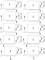
- FIG. 4 shows the four-point tie-down securement system at T 0 , at the moment of a front-side accident.
- the computing device 110 will ascertain that an adverse driving condition has occurred and will prepare to deploy one or more safety devices.
- the computing device 110 may receive data indicating that the vehicle has experienced a large acceleration in the rearward direction, and will conclude that the adverse driving condition is a front-side impact.
- the computing device 110 will then know to trigger fast-acting tensioners for the front-side tie-downs after a first pre-determined time delay has elapsed, where the first pre-determined time delay corresponds to the rebound time for the wheeled mobility device.
- the computing device 110 will then know to trigger fast-acting tensioners for the rear-side tie-downs after a second pre-determined time delay has elapsed, where the second pre-determined time delay corresponds to the secondary rebound time for the wheeled mobility device.
- FIG. 5 shows the four-point tie-down securement system after the front-side collision, at about T 2c , when the wheeled mobility device has completed its initial, forward excursion ( i.e., approximately when the first pre-determined time delay has elapsed).
- wheeled mobility device 310 has moved forward a distance, the rear-side tie-downs 330, 335 have stretched, and the front-side tie-downs 320, 325 have slack in the webbing.
- FIG. 6 shows the four-point tie-down securement system immediately after the computing device 110 has triggered the first safety device ( i.e., after the first pre-determined time delay has elapsed).
- FIG. 7 shows the four-point tie-down securement system at about T 3c , when the wheeled mobility device has completed its secondary, rear excursion ( i . e ., approximately when the second pre-determined time delay has elapsed).
- T 3c the wheeled mobility device 310 has moved rearward a distance, although not as far as it otherwise would if the computing device 110 did not trigger safety devices for the front-side tie-downs 320, 325.
- FIGS. 4-8 demonstrate how an energy management system could be implemented for a wheeled mobility device secured in a forward-facing orientation in a four-point tie-down system while experiencing a front-side collision
- the concepts described above may be applied during a heavy braking event.
- the concepts describe above may be applied in a rear-side collision or heavy acceleration event (except that the safety devices for the rear-side tie-downs would be triggered first).
- the concepts described above may be applied with a rear-facing wheeled mobility device that is experiencing a front-side or rear-side collision, a heavy braking event, or a heavy acceleration event.
- the concepts described above may be applied with a side-facing wheeled mobility device that is experiencing a right- or left-side collision, a long duration turn, or a sharp turn. Even further yet, the concepts described above may be applied in a 3-point tie-down system, where there is a single tie-down for the front-side of the wheeled mobility device.
- FIGS. 9-13 an exemplary implementation of an energy management system is shown to control oscillating excursions in a forward-facing, four-point tie-down securement system during a left-side impact.
- the front-side tie-downs 320, 325 are angled toward each other as they extend from the vehicle attachment points to the wheeled mobility device attachment points
- the rear-side tie-downs 330, 335 are angled away from each other as they extend from the vehicle attachment points to the wheeled mobility device attachment points.
- FIG. 9 shows the four-point tie-down securement system at T 0 , at the moment of a left-side accident.
- the computing device 110 will ascertain that an adverse driving condition has occurred and will prepare to deploy one or more safety devices.
- the computing device 110 may receive data indicating that the vehicle has experienced a large acceleration in the rightward direction, and will conclude that the adverse driving condition is a left-side impact.
- the computing device 110 will then know to trigger fast-acting tensioners for one of the front-side tie-downs and one of the rear-side tie-downs after a first pre-determined time delay has elapsed, where the first pre-determined time delay corresponds to the rebound time for the wheeled mobility device.
- the wheeled mobility device 310 has moved rightward a distance, although not as far as it otherwise would if the computing device 110 did not trigger safety devices for one each of the front-side tie-downs 320, 325 and rear-side tie-downs 330, 335.
- the left-front-side and right-rear-side tie-downs 320, 335 have stretched, and the right-front-side and left-rear-side tie-downs 325, 330 may have slack in the webbing.
- FIG. 12 (as compared to FIG. 11 )
- the left-front-side and right-rear-side tie-downs 320, 335 have stretched, and the right-front-side and left-rear-side tie-downs 325, 330 may have slack in the webbing.
- FIG. 13 shows the four-point tie-down securement system immediately after the computing device 110 has triggered the second safety device ( i.e., after the second pre-determined time delay has elapsed).
- fast-acting tensioners have removed the slack from the webbing in and the right-front-side and left-rear-side tie-downs 325, 330, ideally prior, at or about the time the wheeled mobility device begins its tertiary, leftward excursion. Additional tensioning events may be necessary or desirable in more severe events to address additional oscillations.
- FIGS. 14-18 an exemplary implementation of an energy management system is shown to control oscillating excursions in a forward-facing, four-point tie-down securement system during a left-side impact, when the rear-side tie-downs are installed at non-ideal angles.
- the rear-side tie-downs 330, 335 are angled toward each other as they extend from the vehicle attachment points to the wheeled mobility device attachment points.
- the computing device 110 could be programmed to receive input from external devices 160 that are indicative of the non-ideal angles, other non-ideal securement conditions, and to adapt the computing device's 110 response to an adverse driving condition based on that input.
- the computing device 110 will understand that the left-front-side and left-rear-side tie-downs 320, 330 will experience webbing slack during the initial leftward excursion (see FIG. 15 , as compared to FIG. 10 with ideal angles) and will trigger safety devices for the two left-side tie-downs at about T 2c (see FIG. 16 ).
- the computing device 110 will understand that the right-front-side and right-rear-side tie-downs 325, 335 will experience webbing slack during the secondary rightward excursion (see FIG. 17 , as compared to FIG. 12 with ideal angles) and will trigger safety devices for the two right-side tie-downs at about T 3c (see FIG. 18 ).
- FIG. 23 shows the three-point tie-down securement system immediately after the computing device 110 has triggered the second safety device ( i.e. , after the second pre-determined time delay has elapsed).
- the second safety device i.e. , after the second pre-determined time delay has elapsed.
- fast-acting tensioners have removed the slack from the webbing in the rear-side tie-downs 330, 335, ideally prior, at or about the time the wheeled mobility device begins its tertiary, forward excursion.
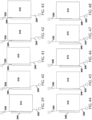
- FIGS. 19-23 demonstrate how an energy management system could be implemented for a wheeled mobility device secured in a forward-facing orientation in a three-point tie-down system while experiencing a front-side collision
- the concepts described above may be applied during a heavy braking event.
- the concepts describe above may be applied in a rear-side collision or heavy acceleration event (except that the safety devices for the rear-side tie-downs would be triggered first).
- the concepts described above may be applied with a rear-facing wheeled mobility device that is experiencing a front-side or rear-side collision, a heavy braking event, or a heavy acceleration event (since the two tie-downs would always be disposed toward the rear of the vehicle, for added strength in front-side collisions).
- FIG. 24 shows the three-point tie-down securement system at T 0 , at the moment of a left-side accident.
- the wheeled mobility device is spaced from the bumper 340, but it could be touching, exerting pressure on, or compressing the bumper 340.
- the computing device 110 will ascertain that an adverse driving condition has occurred and will prepare to deploy one or more safety devices.
- the computing device 110 may receive data indicating that the vehicle has experienced a large acceleration in the rightward direction, and will conclude that the adverse driving condition is a left-side impact.
- the computing device 110 will then know to trigger fast-acting tensioners for the left-front-side tie-down and one of the rear-side tie-downs after a first pre-determined time delay has elapsed, where the first pre-determined time delay corresponds to the rebound time for the wheeled mobility device.
- the computing device 110 will then know to trigger a fast-acting tensioner for the other rear-side tie-down and a fast-acting safety device for moving the bumper 340 toward the wheeled mobility device after a second pre-determined time delay has elapsed, where the second pre-determined time delay corresponds to the secondary rebound time for the wheeled mobility device.
- the wheeled mobility device 310 has moved rightward a distance, although not as far as it otherwise would if the computing device 110 did not trigger safety devices for the left-front-side and right-rear-side tie-downs 320, 335.
- the left-front-side and right-rear-side tie-downs 320, 335 have stretched, there is slack in the strap of the left-rear-side tie down 330, and the wheeled mobility device 310 has moved away from the bumper 340, where there is a space between the two, and a fast-acting tensioner has removed slack from the strap of the left-rear-side tie-down 330.
- FIG. 29 shows the securement system at T 0 , at the moment of a front-side accident.
- the computing device 110 will ascertain that an adverse driving condition has occurred and will prepare to deploy one or more safety devices.
- the computing device 110 may receive data indicating that the vehicle has experienced a large acceleration in the rearward direction, and will conclude that the adverse driving condition is a front-side impact.
- the computing device 110 will then know to trigger a fast-acting device for moving the bumper 340 after a first pre-determined time delay has elapsed, where the first pre-determined time delay corresponds to the rebound time for the wheeled mobility device.
- the computing device 110 will then know to trigger fast-acting tensioners for the rear-side tie-downs after a second pre-determined time delay has elapsed, where the second pre-determined time delay corresponds to the secondary rebound time for the wheeled mobility device.
- FIG. 30 shows the two-point tie-down securement system after the front-side collision, at about T 2c , when the wheeled mobility device has completed its initial, forward excursion ( i.e., approximately when the first pre-determined time delay has elapsed).
- wheeled mobility device 310 has moved forward a distance, the rear-side tie-downs 330, 335 have stretched, and a space or gap has formed between the bumper 340 and the wheeled mobility device 310.
- FIG. 31 shows the two-point tie-down securement system immediately after the computing device 110 has triggered the first safety device ( i.e. , after the first pre-determined time delay has elapsed).
- FIG. 32 shows the two-point tie-down securement system at about T 3c , when the wheeled mobility device has completed its secondary, rear excursion ( i . e ., approximately when the second pre-determined time delay has elapsed).
- FIG. 32 shows the two-point tie-down securement system immediately after the computing device 110 has triggered the second safety device ( i.e., after the second pre-determined time delay has elapsed).
- FIG. 33 shows the two-point tie-down securement system immediately after the computing device 110 has triggered the second safety device ( i.e., after the second pre-determined time delay has elapsed).
- fast-acting tensioners have removed the slack from the webbing in the rear-side tie-downs 330, 335, ideally prior, at or about the time the wheeled mobility device begins its tertiary, forward excursion. Additional bumper movement and tensioning events may be necessary or desirable in more severe vents to address additional oscillations.
- FIGS. 29-33 demonstrate how an energy management system could be implemented for a wheeled mobility device secured in a forward-facing orientation in a two-point tie-down system while experiencing a front-side collision
- the concepts described above may be applied during a heavy braking event.
- the concepts describe above may be applied in a rear-side collision or heavy acceleration event (except that the safety devices for the rear-side tie-downs would be triggered first).
- the concepts described above may be applied with a rear-facing wheeled mobility device that is experiencing a front-side or rear-side collision, a heavy braking event, or a heavy acceleration event.
- the concepts described above may be applied with a side-facing wheeled mobility device that is experiencing a right-side or left-side collision, or a long duration or sharp turn. Even further yet, the concepts described above for the moveable bumper 340 may be applied to the use of a bumper in a four-point system or for a compression-based bumper system, like the Q' Straint Quantum.
- FIG. 34 shows the two-point tie-down securement system at T 0 , at the moment of a left-side accident.
- the computing device 110 will ascertain that an adverse driving condition has occurred and will prepare to deploy one or more safety devices.
- the computing device 110 may receive data indicating that the vehicle has experienced a large acceleration in the rightward direction, and will conclude that the adverse driving condition is a left-side impact.
- the computing device 110 will then know to trigger fast-acting tensioners for one of the rear-side tie-downs after a first pre-determined time delay has elapsed, where the first pre-determined time delay corresponds to the rebound time for the wheeled mobility device.
- the computing device 110 will then know to trigger a fast-acting tensioner for the other rear-side tie-down after a second pre-determined time delay has elapsed, where the second pre-determined time delay corresponds to the secondary rebound time for the wheeled mobility device.
- FIG. 37 shows the two-point tie-down securement system at about T 3c , when the wheeled mobility device has completed its secondary, rightward excursion ( i.e. , approximately when the second pre-determined time delay has elapsed).
- T 3c the wheeled mobility device 310 has moved rightward a distance, although not as far as it otherwise would if the computing device 110 did not trigger the safety device for the right-rear-side tie-down 335.
- FIG. 37 shows the three-point tie-down securement system immediately after the computing device 110 has triggered the second safety device (i.e. , after the second pre-determined time delay has elapsed).
- FIG. 37 it can be seen that a fast-acting tensioner has removed the slack from the webbing in the left-rear-side tie-down 330, ideally prior, at or about the time the wheeled mobility device begins its tertiary, leftward excursion. Additional tensioning events may be necessary or desirable in more severe vents to address additional oscillations.
- FIGS. 34-38 demonstrate how an energy management system could be implemented for a wheeled mobility device secured in a forward-facing orientation in a two-point tie-down system while experiencing a left-side collision
- the concepts described above may be applied during a right-side collision, a long duration turn, or a sharp turn event.
- the concepts described above may be applied with a side-facing wheeled mobility device that is experiencing a front- or rear-side collision.
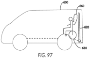
- FIGS. 39-43 an exemplary implementation of an energy management system is shown to control oscillating excursions in a forward-facing, two-point tie-down and bumper securement system during a front-side impact, with the tie-downs and bumper located at the left side of the wheeled mobility device.
- a wheeled mobility device 310 being secured by a left-front-side tie-down 320, a left-rear-side tie-down 330, and a bumper 340 located at the left side of the wheeled mobility device.
- the bumper 340 may be stationary, may be moveable between a retracted and extended position (where by bumper will be close to, touching, or pushing the wheeled mobility device), or may be biased outward using springs or the like.
- FIG. 39 shows the securement system at T 0 , at the moment of a front-side accident.
- the computing device 110 will ascertain that an adverse driving condition has occurred and will prepare to deploy one or more safety devices.
- the computing device 110 may receive data indicating that the vehicle has experienced a large acceleration in the rearward direction, and will conclude that the adverse driving condition is a front-side impact.
- the computing device 110 will then know to trigger a fast-acting tensioner for the front-left-side tie-down 320 after a first pre-determined time delay has elapsed, where the first pre-determined time delay corresponds to the rebound time for the wheeled mobility device.
- the computing device 110 will then know to trigger fast-acting tensioners for the left-rear-side tie-down 330 after a second pre-determined time delay has elapsed, where the second pre-determined time delay corresponds to the secondary rebound time for the wheeled mobility device.
- FIG. 40 shows the two-point tie-down securement system after the front-side collision, at about T 2c , when the wheeled mobility device has completed its initial, forward excursion ( i.e., approximately when the first pre-determined time delay has elapsed).
- wheeled mobility device 310 has moved forward a distance, the left-rear-side tie-down 330 has stretched, and slack has formed in the webbing of the front-left-side tie-down 320.
- FIG. 41 shows the two-point tie-down securement system immediately after the computing device 110 has triggered the first safety device ( i.e., after the first pre-determined time delay has elapsed).
- FIG. 42 shows the two-point tie-down securement system at about T 3c , when the wheeled mobility device has completed its secondary, rear excursion ( i . e ., approximately when the second pre-determined time delay has elapsed).
- T 3c the wheeled mobility device 310 has moved rearward a distance, although not as far as it otherwise would if the computing device 110 did not trigger a safety device for the front-left-side tie-down 320.
- FIG. 43 shows the two-point tie-down securement system immediately after the computing device 110 has triggered the second safety device (i.e., after the second pre-determined time delay has elapsed).
- fast-acting tensioners have removed the slack from the webbing in the left-rear-side tie-down 330, ideally prior, at or about the time the wheeled mobility device begins its tertiary, forward excursion. Additional tensioning events may be necessary or desirable in more severe vents to address additional oscillations.
- FIGS. 39-43 demonstrate how an energy management system could be implemented for a wheeled mobility device secured in a forward-facing orientation in a two-point tie-down system while experiencing a front-side collision
- the concepts described above may be applied during a heavy braking event.
- the concepts describe above may be applied in a rear-side collision or heavy acceleration event (except that the safety devices for the rear-side tie-downs would be triggered first).
- the concepts described above may be applied with a rear-facing wheeled mobility device that is experiencing a front-side or rear-side collision, a heavy braking event, or a heavy acceleration event.
- the concepts described above may be applied with a side-facing wheeled mobility device that is experiencing a right-side or left-side collision, or a long duration or sharp turn.
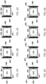
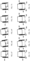
- FIGS. 44-48 an exemplary implementation of an energy management system is shown to control oscillating excursions in a forward-facing, two-point tie-down and bumper securement system during a left-side impact, with the tie-downs and bumper located at the left side of the wheeled mobility device.
- the bumper 340 as shown is moveable both left and right in the event of an adverse driving condition, but may be stationary or biased using springs or the like.
- FIG. 44 shows the two-point tie-down securement system at T 0 , at the moment of a left-side accident. As shown, the wheeled mobility device is touching the bumper 340, but it could be spaced the bumper 340. At about this time, the computing device 110 will ascertain that an adverse driving condition has occurred and will prepare to deploy one or more safety devices. In one embodiment, the computing device 110 may receive data indicating that the vehicle has experienced a large acceleration in the rightward direction, and will conclude that the adverse driving condition is a left-side impact.
- the computing device 110 will then know to trigger a fast-acting tensioner for the front-left-side tie-down after a first pre-determined time delay has elapsed, where the first pre-determined time delay corresponds to the rebound time for the wheeled mobility device.
- the computing device 110 will then know to trigger a fast-acting tensioner for the right-rear-side tie-down and a fast-acting safety device for moving the bumper 340 toward the wheeled mobility device after a second pre-determined time delay has elapsed, where the second pre-determined time delay corresponds to the secondary rebound time for the wheeled mobility device.
- FIG. 45 shows the two-point tie-down securement system after the left-side collision, at about T 2c , when the wheeled mobility device has completed its initial, leftward excursion ( i.e., approximately when the first pre-determined time delay has elapsed).
- the wheeled mobility device has compressed the bumper 340, although depending on the severity of the accident, it may be spaced from or just touching the bumper 340.
- wheeled mobility device 310 has moved left a distance, the left-rear-side tie-down 330 has stretched, and the left-front-side tie-down 320 has slack in the webbing.
- FIG. 45 shows the two-point tie-down securement system after the left-side collision, at about T 2c , when the wheeled mobility device has completed its initial, leftward excursion ( i.e., approximately when the first pre-determined time delay has elapsed).
- the wheeled mobility device has compressed the bumper 340, although depending on the severity of the accident, it may be spaced
- FIG. 46 shows the two-point tie-down securement system immediately after the computing device 110 has triggered the first safety device ( i.e., after the first pre-determined time delay has elapsed).
- FIG. 46 it can be seen that fast-acting tensioners have removed the slack from the webbing in the left-front-side tie-downs 320, ideally prior, at or about the time the wheeled mobility device begins its rightward excursion.
- FIG. 47 shows the two-point tie-down securement system at about T 3c , when the wheeled mobility device has completed its secondary, rightward excursion ( i.e., approximately when the second pre-determined time delay has elapsed).
- the wheeled mobility device 310 has moved rightward a distance, although not as far as it otherwise would if the computing device 110 did not trigger a safety device for the left-front-side tie-downs 320.
- FIG. 47 (as compared to FIG. 46 ), the left-front-side tie-down 320 has stretched, the left-rear-side tie-down 330 has slack in the strap, and the wheeled mobility device 310 has moved away from the bumper 340, where there is a space between the two.
- FIG. 48 shows the two-point tie-down securement system immediately after the computing device 110 has triggered the second safety device ( i.e., after the second pre-determined time delay has elapsed).
- the second safety device i.e., after the second pre-determined time delay has elapsed.
- the safety device (such as an airbag, or fast-acting movement mechanism, or other movement devices) has moved the bumper 340 rightward toward the wheeled mobility device to eliminate (as shown) or lessen the space between the two, and a fast-acting tensioner has removed slack in the strap of the left-rear-side tie-down 330.
- the computing device 110 moves the bumper 340 toward the wheeled mobility device and the fast-acting tensioner has removed the slack ideally prior, at or about the time the wheeled mobility device begins its tertiary, leftward excursion. Additional bumper movement and tensioning events may be necessary or desirable in more severe vents to address additional oscillations.
- FIGS. 44-48 demonstrate how an energy management system could be implemented for a wheeled mobility device secured in a forward-facing orientation in a two-point tie-down system while experiencing a left-side collision
- the concepts described above may be applied during a right-side collision, a long duration turn, or a sharp turn event.
- the concepts described above may be applied with a side-facing wheeled mobility device that is experiencing a front- or rear-side collision.
- the concepts described above for the moveable bumper 340 may be applied to the use of a bumper in a four-point system or for a compression-based bumper system, like the Q'Straint Quantum.
- FIGS. 49-53 an exemplary implementation of an energy management system is shown to control oscillating excursions in a forward-facing, two-point tie-down and bumper securement system during a front-side impact, with the tie-downs located at opposite corners and the bumper located at the left side of the wheeled mobility device.
- a wheeled mobility device 310 being secured by a right-front-side tie-down 325, a left-rear-side tie-down 330, and a bumper 340 located at the left side of the wheeled mobility device.
- the bumper 340 may be stationary, may be moveable between a retracted and extended position (where by bumper will be close to, touching, or pushing the wheeled mobility device), or may be biased outward using springs or the like.
- FIG. 49 shows the securement system at T 0 , at the moment of a front-side accident.
- the computing device 110 will ascertain that an adverse driving condition has occurred and will prepare to deploy one or more safety devices.
- the computing device 110 may receive data indicating that the vehicle has experienced a large acceleration in the rearward direction, and will conclude that the adverse driving condition is a front-side impact.
- the computing device 110 will then know to trigger a fast-acting tensioner for the right-front-side tie-down 325 after a first pre-determined time delay has elapsed, where the first pre-determined time delay corresponds to the rebound time for the wheeled mobility device.
- FIG. 50 shows the two-point tie-down securement system after the front-side collision, at about T 2c , when the wheeled mobility device has completed its initial, forward excursion ( i.e., approximately when the first pre-determined time delay has elapsed).
- wheeled mobility device 310 has moved forward a distance, the left-rear-side tie-down 330 has stretched, and slack has formed in the webbing of the right-front-side tie-down 325.
- FIG. 51 shows the two-point tie-down securement system immediately after the computing device 110 has triggered the first safety device ( i.e., after the first pre-determined time delay has elapsed).
- FIG. 52 shows the two-point tie-down securement system at about T 3c , when the wheeled mobility device has completed its secondary, rear excursion ( i . e ., approximately when the second pre-determined time delay has elapsed).
- T 3c the wheeled mobility device 310 has moved rearward a distance, although not as far as it otherwise would if the computing device 110 did not trigger a safety device for the right-front-side tie-down 325.
- FIG. 53 shows the two-point tie-down securement system immediately after the computing device 110 has triggered the second safety device ( i.e., after the second pre-determined time delay has elapsed).
- a fast-acting tensioner has removed the slack from the webbing in the left-rear-side tie-down 330, ideally prior, at or about the time the wheeled mobility device begins its tertiary, forward excursion. Additional tensioning events may be necessary or desirable in more severe vents to address additional oscillations.
- FIGS. 49-53 demonstrate how an energy management system could be implemented for a wheeled mobility device secured in a forward-facing orientation in a two-point tie-down system while experiencing a front-side collision
- the concepts described above may be applied during a heavy braking event.
- the concepts describe above may be applied in a rear-side collision or heavy acceleration event (except that the safety devices for the rear-side tie-downs would be triggered first).
- the concepts described above may be applied with a rear-facing wheeled mobility device that is experiencing a front-side or rear-side collision, a heavy braking event, or a heavy acceleration event.
- the concepts described above may be applied with a side-facing wheeled mobility device that is experiencing a right-side or left-side collision, or a long duration or sharp turn.
- FIGS. 54-58 an exemplary implementation of an energy management system is shown to control oscillating excursions in a forward-facing, two-point tie-down and bumper securement system during a left-side impact, with the tie-downs located at opposite corners and bumper located at the left side of the wheeled mobility device.
- the bumper 340 as shown is moveable both left and right in the event of an adverse driving condition, but may be stationary or biased using springs or the like.
- FIG. 54 shows the two-point tie-down securement system at T 0 , at the moment of a left-side accident. As shown, the wheeled mobility device is touching the bumper 340, but it could be spaced the bumper 340. At about this time, the computing device 110 will ascertain that an adverse driving condition has occurred and will prepare to deploy one or more safety devices. In one embodiment, the computing device 110 may receive data indicating that the vehicle has experienced a large acceleration in the rightward direction, and will conclude that the adverse driving condition is a left-side impact.
- the computing device 110 will then know to trigger a fast-acting tensioner for the left-rear-side tie-down after a first pre-determined time delay has elapsed, where the first pre-determined time delay corresponds to the rebound time for the wheeled mobility device.
- the computing device 110 will then know to trigger a fast-acting tensioner for the right-front-side tie-down and a fast-acting safety device for moving the bumper 340 toward the wheeled mobility device after a second pre-determined time delay has elapsed, where the second pre-determined time delay corresponds to the secondary rebound time for the wheeled mobility device.
- FIG. 55 shows the two-point tie-down securement system after the left-side collision, at about T 2c , when the wheeled mobility device has completed its initial, leftward excursion ( i.e., approximately when the first pre-determined time delay has elapsed).
- the wheeled mobility device has compressed the bumper 340, although depending on the severity of the accident, it may be spaced from or just touching the bumper 340.
- wheeled mobility device 310 has moved left a distance and the left-rear-side tie-down 330 has slack in the webbing.
- FIG. 56 shows the two-point tie-down securement system immediately after the computing device 110 has triggered the first safety device ( i.e., after the first pre-determined time delay has elapsed).
- FIG. 46 it can be seen that fast-acting tensioners have removed the slack from the webbing in the left-rear-side tie-downs 330, ideally prior, at or about the time the wheeled mobility device begins its rightward excursion.
- FIG. 57 shows the two-point tie-down securement system at about T 3c , when the wheeled mobility device has completed its secondary, rightward excursion ( i.e., approximately when the second pre-determined time delay has elapsed).
- the wheeled mobility device 310 has moved rightward a distance, although not as far as it otherwise would if the computing device 110 did not trigger a safety device for the left-rear-side tie-down 330.
- FIG. 57 (as compared to FIG. 56 ), the left-rear-side tie-down 330 has stretched, the right-front-side tie-down 325 has slack in the webbing, and the wheeled mobility device 310 has moved away from the bumper 340, where there is a space between the two.
- FIG. 58 shows the two-point tie-down securement system immediately after the computing device 110 has triggered the second safety device ( i.e., after the second pre-determined time delay has elapsed).
- FIG. 57 it can be seen that a fast-acting tensioner has removed the slack from the webbing in the right-front-side tie-down 325 and the safety device (such as an airbag, or fast-acting movement mechanism, or other movement devices) has moved the bumper 340 rightward toward the wheeled mobility device to eliminate (as shown) or lessen the space between the two.
- the computing device 110 removes the webbing slack and moves the bumper 340 toward the wheeled mobility device ideally prior, at or about the time the wheeled mobility device begins its tertiary, leftward excursion. Additional bumper movements and tensioning events may be necessary or desirable in more severe vents to address additional oscillations.
- FIGS. 54-58 demonstrate how an energy management system could be implemented for a wheeled mobility device secured in a forward-facing orientation in a two-point tie-down system while experiencing a left-side collision
- the concepts described above may be applied during a right-side collision, a long duration turn, or a sharp turn event.
- the concepts described above may be applied with a side-facing wheeled mobility device that is experiencing a front- or rear-side collision.
- the concepts described above for the moveable bumper 340 may be applied to the use of a bumper in a four-point system or for a compression-based bumper system, like the Q'Straint Quantum.
- FIGS. 59-62 an exemplary implementation of an energy management system is shown to control oscillating excursions in a forward-facing, compression-based securement system during a front-side impact.
- FIGS. 59-62 show a wheeled mobility device 310 being secured by a left-side bumper 350, a right-side bumper 360, and a rear-side bumper 370, securing the left, right, and rear side of the wheeled mobility device 310, respectively.
- any one or more of the bumpers may be stationary or may be biased outward (toward the wheeled mobility device 310) using springs or the like, although in this example the bumpers 350, 360, 370 are each moveable between a retracted and extended position (whereby the respective bumper will be close to, touching, or exerting pressure on/pushing the wheeled mobility device).
- the left-side and right-side bumpers 350, 360 are designed to squeeze the wheeled mobility device 310 to prevent unwanted movement during transit. It is obviously desirable to keep the squeezing pressure relatively low during normal transit conditions to avoid damaging the wheeled mobility device.
- the bumpers 350, 360, 370 can each be provided with safety devices that cause the bumpers to quickly exert large squeezing and/or downward forces on the wheeled mobility device 310 in the event of an adverse driving condition.
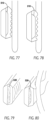
- the left-side and right-side bumpers 350, 360 may optionally include secondary gripping members 355, 365 that are configured to pivot about pivot points 352, 362 from a retracted position ( FIG. 59 ) to an extended position ( FIG. 60 ), whereby the secondary gripping members 355, 365 will be positioned to engage with a forward facing surface or structure of the wheeled mobility device 310, such as the front surface of a wheel.
- the secondary gripping members 355, 365 serve as a secondary safety device that can be deployed in the event of an adverse driving condition.
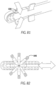
- Other secondary safety devices can optionally be used in the alternative or in combination with the secondary gripping members 355, 365, including but not limited to those disclosed in U.S. Provisional Patent Application No. 62/825,325, filed on March 28, 2019 , such as: pressure bladders 510 built into one or more of the bumpers 350, 360, 370 that are capable of quickly inflating through pneumatics, hydraulics, pyrotechnics, compressed gas containers, or other motive forces to enhance the engagement between contours on the engaging faces of the bumpers with various details on the wheeled mobility device 310 (see FIGS.
- magnetorheological fluid-filled bladders 520 built into one or more of the bumpers 350, 360, 370 that can be energized to create a rigid topography that interlocks with details on the wheeled mobility device 310 surfaces (see FIGS. 79-80 ); various contours, knobs, paddles, fingers, grippers, contour-conforming members, or other extremities 530 that can be quickly deployed to interlock with details on the wheeled mobility device 310 surfaces (see FIG. 81 ); an engaging member 540 that is configured to quickly grab a portion of the wheeled mobility device, such as the wheel hub (see FIG.
- any embodiment, including the tie-down systems described above, could embody and trigger any one or more of these secondary safety devices at an appropriate phase of an adverse driving condition.
- FIG. 59 shows the securement system at T 0 , at the moment of a front-side accident.
- the computing device 110 will ascertain that an adverse driving condition has occurred and will prepare to deploy one or more safety devices.
- the computing device 110 may receive data indicating that the vehicle has experienced a large acceleration in the rearward direction, and will conclude that the adverse driving condition is a front-side impact.
- the computing device 110 will know to trigger one or more of the following safety devices, preferably before T 1c , when the wheeled mobility device begins its forward excursion: (1) a safety device that urges the bumpers 350, 360 toward each other to increase the squeezing force on the wheeled mobility device; (2) a safety device that urges or pivots the bumpers 350, 360 downward to push the wheeled mobility device 310 downward against the floor; and/or (3) one or more secondary safety devices, such as the safety device described above that quickly moves the secondary gripping members 355, 365 into its extended position.
- the computing device will then know to trigger a fast-acting safety device that moves the rear-side bumper 370 after a pre-determined time delay has elapsed, where the pre-determined time delay corresponds to the rebound time for the wheeled mobility device.
- the computing device 110 could be programmed to deploy additional safety devices to control further oscillations.
- FIG. 60 shows the securement system after the front-side collision, at about T 1c , before or approximately when the wheeled mobility device has begun its initial, forward excursion.
- the secondary gripping members 355, 365 have been deployed, and downward force and additional squeezing force have been applied via bumpers 350, 360.
- FIG. 61 shows the securement system at about T 2c , when the wheeled mobility device has completed its initial, forward excursion (i.e., approximately when the pre-determined time delay has elapsed).
- wheeled mobility device 310 has moved forward a distance, the front surfaces of the wheels are pressed against the secondary gripping members 355, 365, and a gap or space has formed between the rear-side bumper 370 and the wheeled mobility device.
- FIG. 62 shows the securement system immediately after the computing device 110 has triggered the safety device for the rear-side bumper 370 ( i.e., after the pre-determined time delay has elapsed). It can be seen that a fast-acting device has moved the rear-side bumper 370 forward to close the gap, ideally prior, at or about the time the wheeled mobility device begins its secondary, rearward excursion.
- FIGS. 59-62 demonstrate how an energy management system could be implemented for a wheeled mobility device secured in a forward-facing orientation in a compression-based system while experiencing a front-side collision
- the concepts described above may be applied during a heavy braking event.
- the concepts describe above may be applied in a rear-side collision or heavy acceleration event.
- the concepts described above may be applied with a rear-facing wheeled mobility device that is experiencing a front-side or rear-side collision, a heavy braking event, or a heavy acceleration event.
- the concepts described above may be applied with a side-facing wheeled mobility device that is experiencing a right-side or left-side collision, or a long duration or sharp turn.
- the concepts described above for the moveable bumpers and secondary safety devices may be applied to the use of a bumper in a tie-down system or other type of securement system.
- FIGS. 63-66 an exemplary implementation of an energy management system is shown to control oscillating excursions in a forward-facing, compression-based securement system during a left-side impact.
- the securement system may optionally include secondary safety devices, such as those in the form of bumpers 380, 390 that are recessed in the floor and configured to deploy upward and outward to make contact with inner-facing surfaces of the wheeled mobility device, such as the inner surfaces of the wheels.
- FIG. 63 shows the securement system at T 0 , at the moment of a left-side accident.
- the computing device 110 will ascertain that an adverse driving condition has occurred and will prepare to deploy one or more safety devices.
- the computing device 110 may receive data indicating that the vehicle has experienced a large acceleration in the rightward direction, and will conclude that the adverse driving condition is a left-side impact.
- the computing device 110 will know to trigger one or more of the following safety devices, preferably before T 1c , when the wheeled mobility device begins its forward excursion: (1) a safety device that urges the bumpers 350, 360 toward each other to increase the squeezing force on the wheeled mobility device; (2) a safety device that urges or pivots the bumpers 350, 360 downward to push the wheeled mobility device 310 downward against the floor; and/or (3) one or more secondary safety devices, such as the safety device described above that quickly moves the in-floor bumpers 380, 390 upward and outward into engagement with inward facing surfaces of the wheeled mobility device 310.
- the computing device will then know to trigger a fast-acting safety device that moves the right-side bumper 360 into contact with the wheeled mobility device 310 after a pre-determined time delay has elapsed, where the pre-determined time delay corresponds to the rebound time for the wheeled mobility device.
- the computing device 110 could be programmed to deploy additional safety devices to control further oscillations, for example quickly moving the left-side bumper 360 into contact with the wheeled mobility device 310 after a secondary rebound.
- FIG. 65 shows the securement system at about T 2c , when the wheeled mobility device has completed its initial, leftward excursion (i.e., approximately when the pre-determined time delay has elapsed). At this point, the wheeled mobility device has moved left a distance and compressed the bumpers 350, 390, and gaps or spaces have formed between the wheeled mobility device and bumpers 360, 380.
- FIG. 66 shows the securement system immediately after the computing device 110 has triggered the safety devices for the bumpers 360, 380 ( i.e., after the first pre-determined time delay has elapsed). It can be seen that a fast-acting device has moved the bumpers 360, 380 to the left to close the gaps, ideally prior, at or about the time the wheeled mobility device begins its secondary, rearward excursion.
- FIGS. 63-66 demonstrate how an energy management system could be implemented for a wheeled mobility device secured in a forward-facing orientation in a compression-based system while experiencing a left-side collision
- the concepts described above may be applied during a right-side collision, a long duration turn, or a sharp turn event.
- the concepts described above may be applied with a side-facing wheeled mobility device that is experiencing a front- or rear-side collision.
- the concepts described above for the moveable bumpers and secondary safety devices may be applied to the use of a bumper in a tie-down system or other type of securement system.
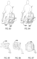
- FIGS. 67-71 an exemplary implementation of an energy management system is shown to control excursions in a forward-facing, tie-down securement system during a vehicle roll-over to the right side.
- the wheeled mobility device 310 is shown in rear plan view with a left-side tie-down 322 and a right-side tie-down 332, each of which could be representative of either or both of a front restraint and a rear restraint, and a bumper 340, which may or may not be present.
- the accompanying description below is applicable in any tie-down based system, whether a four-point, three-point, or two-point system, and whether or not a bumper is present.
- FIG. 67 shows the tie-down securement system at T 0 , at the moment of the rollover to the right side.
- the computing device 110 will ascertain that an adverse driving condition has occurred and will prepare to deploy one or more safety devices.
- the computing device 110 may receive data indicating that the vehicle has experienced a rotation in the clockwise direction, and will conclude that the adverse driving condition is a rollover to the right side.
- the computing device 110 will then know to trigger a fast-acting tensioner for the left-side tie-down(s) 322 after a first pre-determined time delay has elapsed, where the first pre-determined time delay corresponds to the rebound time for the wheeled mobility device.
- the computing device 110 will then know to trigger a fast-acting tensioner for the right-side tie-down 332 and a safety device for moving the bumper 340 into contact with the wheeled mobility device 310 after a second pre-determined time delay has elapsed, where the second pre-determined time delay corresponds to the secondary rebound time for the wheeled mobility device.
- FIG. 68 shows the tie-down securement system after the rollover to the right side of the vehicle, at about T 2c , when the wheeled mobility device 310 has completed its initial excursion in a counterclockwise direction relative to the vehicle ( i.e., approximately when the first pre-determined time delay has elapsed).
- wheeled mobility device 310 has rotated counterclockwise and pushed into the bumper 340, the right-side tie-down 332 has stretched, and the left-side tie-down 322 has slack in the webbing.
- FIG. 70 shows the tie-down securement system at about T 3c , when the wheeled mobility device has completed its secondary, clockwise excursion ( i.e., approximately when the second pre-determined time delay has elapsed).
- FIG. 70 shows the tie-down securement system immediately after the computing device 110 has triggered the second safety devices (i.e., after the second pre-determined time delay has elapsed).
- a fast-acting tensioner has removed the slack from the webbing in the right-side tie-down 322 and the bumper 340 has moved to close the gap, ideally prior, at or about the time the wheeled mobility device begins its tertiary, counterclockwise excursion. Additional bumper movement and tensioning events may be necessary or desirable in more severe events to address additional oscillations.
- FIGS. 67-71 demonstrate how an energy management system could be implemented for a wheeled mobility device secured in a forward-facing, tie-down securement system while experiencing a right-side rollover
- the concepts described above may be applied during a left-side roll-over, a long duration turn, or a sharp turn event.
- the concepts described above may be applied with a rear-facing wheeled mobility device that is experiencing a rollover, or a side-facing wheeled mobility device that is experiencing a front- or rear-side collision.
- the concepts described above may be applicable to control excursions during a right-side or left-side impact for a wheeled mobility device and occupant having a high center of gravity.
- FIGS. 72-76 an exemplary implementation of an energy management system is shown to control oscillating excursions in a forward-facing, compression-based securement system during a right-side rollover.
- the securement system may optionally include secondary safety devices, such as those in the form of bumpers 380, 390 that are recessed in the floor and configured to deploy upward and outward to make contact with inner-facing surfaces of the wheeled mobility device, such as the inner surfaces of the wheels.
- FIG. 72 shows the securement system at T 0 , at the moment of a rollover to the right-side.
- the computing device 110 will ascertain that an adverse driving condition has occurred and will prepare to deploy one or more safety devices.
- the computing device 110 may receive data indicating that the vehicle has experienced a rotation in the clockwise direction, and will conclude that the adverse driving condition is a rollover to the right side.
- the computing device 110 may be programmed to trigger one or more of the following safety devices before T 1c , when the wheeled mobility device begins its forward excursion: (1) a safety device that urges the bumpers 350, 360 toward each other to increase the squeezing force on the wheeled mobility device; (2) a safety device that urges or pivots the bumpers 350, 360 downward to push the wheeled mobility device 310 downward against the floor; and/or (3) one or more secondary safety devices, such as the safety device described above that quickly moves the in-floor bumpers 380, 390 upward and outward into engagement with inward facing surfaces of the wheeled mobility device 310. Additionally or alternatively (the alternative scenario being shown in FIGS.
- the computing device may be programmed to trigger a fast-acting safety device that moves the right-side bumpers 360, 390 into contact with the wheeled mobility device 310 after a first pre-determined time delay has elapsed, where the first pre-determined time delay corresponds to the rebound time for the wheeled mobility device.
- the computing device may also be programmed to trigger a fast-acting safety device that moves the left-side bumpers 350, 380 into contact with the wheeled mobility device 310 after a second pre-determined time delay has elapsed, where the second pre-determined time delay corresponds to the secondary rebound time for the wheeled mobility device.
- FIG. 73 shows the securement system after the rollover to the right side of the vehicle, at about T 2c , when the wheeled mobility device has completed its initial excursion in a counterclockwise direction relative to the vehicle ( i.e., approximately when the first pre-determined time delay has elapsed).
- the wheeled mobility device has rotated counterclockwise (relative to the vehicle) and pushed into the bumper 350, and a gap or space has formed between the wheeled mobility device and bumper 360.
- FIG. 74 shows the securement system immediately after the computing device 110 has triggered the safety devices for the bumpers 360, 390 ( i.e., after the first pre-determined time delay has elapsed). It can be seen that a fast-acting device has moved the bumpers 360, 390 toward the wheeled mobility device to close the gap, ideally prior, at or about the time the wheeled mobility device begins its secondary excursion in the clockwise direction.
- FIG. 75 shows the securement system at about T 3c , when the wheeled mobility device has completed its secondary, clockwise excursion ( i.e., approximately when the second pre-determined time delay has elapsed).
- the wheeled mobility device 310 has rotated clockwise relative to the vehicle, although not as far as it otherwise would if the computing device 110 did not trigger safety devices for the bumpers 360, 290.
- FIG. 75 (as compared to FIG. 74 ), the wheeled mobility device has pushed into both bumpers 360, 390, and a gap or space may have formed between bumper 350 and the wheeled mobility device 310.
- FIG. 76 shows the securement system immediately after the computing device 110 has triggered the second safety devices ( i.e ., after the second pre-determined time delay has elapsed).
- the second safety devices i.e ., after the second pre-determined time delay has elapsed.
- a fast-acting safety device has moved bumpers 350, 380 toward the wheeled mobility device to close the gap, ideally prior, at or about the time the wheeled mobility device begins its tertiary, counterclockwise excursion. Additional bumper movement events may be necessary or desirable in more severe events to address additional oscillations.
- FIGS. 72-76 demonstrate how an energy management system could be implemented for a wheeled mobility device secured in a forward-facing, compression-based securement system while experiencing a right-side rollover
- the concepts described above may be applied during a left-side roll-over, a long duration turn, or a sharp turn event.
- the concepts described above may be applied with a rear-facing wheeled mobility device that is experiencing a rollover, or a side-facing wheeled mobility device that is experiencing a front- or rear-side collision.
- the concepts described above may be applicable to control excursions during a right-side or left-side impact for a wheeled mobility device and occupant having a high center of gravity.
- FIGS. 4-76 for purposes of simplicity, were described as having a computing device that was programmed to assume how the various belts and/or bumpers would react in an accident, and to trigger safety devices based on that assumption.
- the computing device can monitor the dynamic characteristics of the vehicle and/or the wheeled mobility device and/or the securement system and to trigger safety devices based on the actual response of the system.
- the computing device can monitor the status of the securement system through various sensors, such as tension sensors for tie downs and pressure or proximity sensors for bumpers.
- the computing device will be able to detect where slack or gaps are forming (e.g ., based on sensing a fast reduction in tension or pressure, a proximity sensor or switch, etc.) and to trigger one or more safety devices to remove such slack or gaps at the appropriate time.
- Tightening the rear-side tie-downs 330, 335 may prevent or minimize the slack created in the front-side tie-downs 320, 325.
- the tension on the rear-side tie-downs 330, 335 can be released and/or tensioning devices for the front-side tie-downs 320, 325 can be triggered.
- a similar procedure can be followed for subsequent oscillations, and for scenarios where the vehicle experiences a forward acceleration.
- the forward-facing four-point tie-down system shown in FIG. 9 in a sharp right turning event or other scenario whether the vehicle experiences a rightward acceleration, it may be preferable to trigger tensioning devices for the right-front-side tie-down 325 and left-rear-side tie-down 330 to prevent or minimize leftward movement of the wheeled mobility device, preferably at the same time or shortly after the computing system detects a rightward acceleration.
- the amount of tension applied can be selected or adjusted over time based on the magnitude of the acceleration experienced by the vehicle.
- Tightening the right-front-side tie-down 325 and left-rear-side tie-down 330 may prevent or minimize the slack created in the left-front-side tie-down 320 and right-rear-side tie-down 335.
- the tension on the right-front-side tie-down 325 and left-rear-side tie-down 330 can be released and/or tensioning devices for the left-front-side tie-down 320 and right-rear-side tie-down 335 can be triggered.
- a similar procedure can be followed for subsequent oscillations, and for scenarios where the vehicle experiences a leftward acceleration.
- a tensioning device for the left-rear-side tie-down 330 and a safety device to move the bumper 340 into contact with the wheeled mobility device to prevent or minimize leftward movement of the wheeled mobility device, preferably at the same time or shortly after the computing system detects a rightward acceleration.
- the amount of tension applied by the tie-down and/or pressure applied by the bumper can be selected or adjusted over time based on the magnitude of the acceleration experienced by the vehicle.
- Tightening the left-rear-side tie-down 330 and moving the bumper 340 into contact with the wheeled mobility device may prevent or minimize the slack created in the left-front-side tie-down 320 and right-rear-side tie-down 335.
- the tension on the left-rear-side tie-down 330 and the pressure exerted by the bumper 340 can be released and/or tensioning devices for the left-front-side tie-down 320 and right-rear-side tie-down 335 can be triggered.
- a similar procedure can be followed for subsequent oscillations, and for scenarios where the vehicle experiences a leftward acceleration.
- the forward-facing compression-based securement system shown in FIG. 59 in a heavy acceleration event or other scenario whether the vehicle experiences a forward acceleration, it may be preferable to trigger safety devices to apply additional squeezing force on the wheeled mobility device 310 with the bumpers 350, 360, and forward force on the wheeled mobility device 310 with bumper 370 to prevent or minimize rearward movement of the wheeled mobility device, preferably at the same time or shortly after the computing system detects a forward acceleration of the vehicle.
- the amount of pressure applied by the bumper can be selected or adjusted over time based on the magnitude of the acceleration experienced by the vehicle. These actions may prevent or minimize the gap or space created between the wheeled mobility device 310 and the bumper 370. At or about the time of the anticipated or actual rebound, the pressure exerted by the bumper 370 can be released.
- a similar procedure can be followed for subsequent oscillations, and for scenarios where the vehicle experiences a rearward acceleration.
- a safety device to move the bumpers 350 and/or 390 into contact with the wheeled mobility device to prevent or minimize leftward movement of the wheeled mobility device, preferably at the same time or shortly after the computing system detects a rightward acceleration.
- the amount of pressure applied by the bumpers can be selected or adjusted over time based on the magnitude of the acceleration experienced by the vehicle. Moving the bumpers 350 and/or 390 into contact with the wheeled mobility device may prevent or minimize the gap or space created between the wheeled mobility device 310 and the bumper 360.
- the pressure exerted by the bumper 350 and/or 390 can be released and/or safety devices for the bumpers 360 and/or 380 can be triggered to move them into contact with the wheeled mobility device 310.
- a similar procedure can be followed for subsequent oscillations, and for scenarios where the vehicle experiences a leftward acceleration.
- a tensioning device for the right-side tie-down 332 and/or a safety device for the bumper 340 to move it into contact with the wheeled mobility device 310, to prevent or minimize tipping (counterclockwise rotation) of the wheeled mobility device, preferably at the same time or shortly after the computing system detects a rightward acceleration or clockwise rotation of the vehicle.
- the amount of tension applied by the tie-down and/or pressure applied by the bumper can be selected or adjusted over time based on the magnitude of the acceleration experienced by the vehicle.
- Tightening the right-side tie-down 332 and/or moving the bumper 340 may prevent or minimize the slack created in the left- side tie-down 322.
- the tension on the right-side tie-down 332 and the pressure applied by the bumper 340 can be released and/or a tensioning device for the left-side tie-down 322 can be triggered.
- a similar procedure can be followed for subsequent oscillations, and for scenarios where the vehicle experiences a leftward acceleration or counterclockwise rotation.
- a safety device for bumper 350 to apply inward pressure to the wheeled mobility device 310 and/or
- a safety device for bumper 360 to apply downward pressure to the wheeled mobility device 310 and/or
- a safety device for bumper 390 to move bumper 390 into contact with the wheeled mobility device 310, preferably at the same time or shortly after the computing system detects a rightward acceleration or clockwise rotation of the vehicle.
- the amount of pressure applied by the bumpers can be selected or adjusted over time based on the magnitude of the acceleration experienced by the vehicle.
- the pressure applied by the bumpers 350 and/or 360 and/or 390 can be released and/or the computing device can trigger (a) a safety device for bumper 360 to apply inward pressure to the wheeled mobility device 310 and/or (b) a safety device for bumper 350 to apply downward pressure to the wheeled mobility device 310 and/or (c) a safety device for bumper 380 to move bumper 380 into contact with the wheeled mobility device 310.
- a similar procedure can be followed for subsequent oscillations, and for scenarios where the vehicle experiences a leftward acceleration or counterclockwise rotation.
- the computing device can trigger safety devices that (a) create or close a gap between the wheeled mobility device; (b) reduce or increase the pressure exerted by the wheeled mobility device on the passenger; and/or (c) reduce or increase the pressure exerted by the occupant belts on the passenger.
- the computing device can trigger safety devices designed to minimize the change in distance between the wheeled mobility device 10 and the passenger 5.
- the computing device can trigger a tensioning device for the rear tie-downs 20 before, at, or about T 1c to delay or slow the forward excursion to prevent a gap between the wheeled mobility device 10 and passenger 5 from closing.
- the amount of tension applied can be selected or adjusted over time based on the gap between the wheeled mobility device or the rate of change in the gap.
- the computing device can trigger a safety device for the occupant restraint retractors to allow some webbing to slowly release over time, thereby allowing the passenger to move at or about the same pace as the wheeled mobility device.
- the rate of release can be selected or adjusted over time based on the gap between the wheeled mobility device or the rate of change in the gap.
- the computing device can trigger a tensioning device for the front tie-downs 30 to cause the wheeled mobility device 10 (a) to continue its forward excursion, thereby allowing the wheeled mobility device to continue its forward excursion at or about the same pace as the passenger, and/or (b) to delay or slow the rearward excursion of the wheeled mobility device to prevent a gap between the wheeled mobility device 10 and passenger 5 from increasing.
- the amount of tension applied can be selected or adjusted over time based on the gap between the wheeled mobility device or the rate of change in the gap.
- the computing device can trigger a tensioning device for the rear tie-downs 20 to cause the wheeled mobility device 10 (a) to continue its rearward excursion, thereby allowing the wheeled mobility device to continue its forward excursion at or about the same pace as the passenger, and/or (b) to delay or slow the forward excursion of the wheeled mobility device to prevent a gap between the wheeled mobility device 10 and passenger 5 from closing.
- the amount of tension applied can be selected or adjusted over time based on the gap between the wheeled mobility device or the rate of change in the gap.
- the computing device can track the anticipated or actual position of the wheeled mobility device and the passenger, and make continuous adjustments during the entire adverse driving scenario to: (a) keep the space between the two relatively constant, (b) keep the space between the two above a lower threshold, or between an upper and lower threshold, (c) keep the force exerted on the passenger by one or both of the wheeled mobility device and occupant restraints below a threshold, or between upper and lower thresholds, and/or (d) keep the squeezing force below a threshold or between an upper and lower threshold.
- the computing device will monitor the force being exerted on the passenger 5 by the occupant restraints, and cause a slow release of webbing from the occupant restraint retractors when the force exceeds a certain threshold.
- the rate of release can be increased if the force continues to increase above a second threshold, in proportion to the rate of increase in force, or based on the rate of increase in force.
- the computing device will monitor the squeezing force being exerted on the passenger 5 by the wheeled mobility device 10 and the occupant restraints, and if the squeezing force exceeds a certain threshold, trigger safety devices that allow webbing to be released from the occupant restraint retractors and/or slow the forward excursion of the wheeled mobility device and/or allow or cause the wheeled mobility device to accelerate rearward.
- one or more airbags 401, 402, 403, 404 can placed on one or more, or each, of the front-side, rear-side, left-side, and right-side of the wheeled mobility device 410, and can be used to control excursions of the wheeled mobility device 410.
- the front-side airbag 401 can be triggered to control the forward excursion of the wheeled mobility device 410.
- the rear-side airbag 402 can be triggered to control the rearward excursion.
- Additional airbags could be triggered to control subsequent rebounds and oscillations. The opposite would occur in a rear-side impact.
- the left-side airbag 403 can be triggered to control the leftward excursion of the wheeled mobility device 410.
- the right-side airbag 404 can be triggered to control the rightward excursion. Additional airbags could be triggered to control subsequent rebounds and oscillations. The opposite would occur in a right-side impact.
- the airbag 640 deploys from the ramp 620.
- the airbag 650 deploys from a surface or structure of the vehicle 600, such as the ceiling, wall, or pillar.
- the airbag 660 may be integrated into and deploy from the wheeled mobility device 610.
- the airbags 640, 650, 660 can be triggered at, about, or after the passenger begins its rebound in the rear direction. In a rear-side impact, the airbags 640, 650, 660 can be triggered when the accident is detected, or at, about, or after the passenger begins its rearward excursion.
- the computing system can monitor the dynamic status of the passenger and deploy the airbags 640, 650, 660 when rearward movement of the passenger or the passenger's head is detected.
- the airbag can be large, and/or control rearward excursion of one or more of the passenger's head, passenger's back, the seat back of the wheeled mobility device, and the wheeled mobility device.
- wheeled mobility device securement systems are shown in the Figures and described above, it is contemplated that the principles described above can be modified for use in any wheeled mobility device securement system, and any configuration (forward-facing, rearward facing, etc.).
- any wheeled mobility device securement system and any configuration (forward-facing, rearward facing, etc.).
- adverse driving scenarios are shown and described above, it is contemplated that the principles described above can be modified to be appropriate for other adverse driving scenarios.
- the principles described above can be used for securement of other types of mobility devices, including walkers, strollers, buggies, infant and toddler car seat and boosters, etc.
- wheeled mobility device and wheelchair are used interchangeably herein, and are intended to broadly encompass all types of wheeled mobility devices including manual and powered wheelchairs and scooters.
- tie-downs comprising webbing
- tie-downs can take many forms, including for example cords and cables, and the principles described herein are applicable to securement systems using any form of tie-down.
- the concepts described above may be applied in mirror image securement systems.
- the three point system shown in FIGS. 19-28 may have a right-front-side tie down, rather than the left-front-side tie down 320, and may also have the bumper 340 located on the right side, rather than the left.
- any securement system may incorporate one or more bumpers located on any one or more of the four sides of the wheeled mobility device, which may be controlled to reduce excursions in the manners described herein.
Landscapes
- Public Health (AREA)
- Health & Medical Sciences (AREA)
- Engineering & Computer Science (AREA)
- Mechanical Engineering (AREA)
- Animal Behavior & Ethology (AREA)
- Life Sciences & Earth Sciences (AREA)
- General Health & Medical Sciences (AREA)
- Veterinary Medicine (AREA)
- Theoretical Computer Science (AREA)
- Multimedia (AREA)
- General Physics & Mathematics (AREA)
- Physics & Mathematics (AREA)
- Automotive Seat Belt Assembly (AREA)
- Electric Propulsion And Braking For Vehicles (AREA)
Claims (15)
- System zum Steuern der Energie in einem Sicherungssystem für eine Mobilitätsvorrichtung (10, 310, 410, 610), die vorübergehend an einem Fahrzeug (195, 600) befestigt wird, während einer widrigen Fahrbedingung, wobei das System ein Rechensystem (110) umfasst, das einen Prozessor (120) enthält, der konfiguriert ist zum:Feststellen, dass die widrige Fahrbedingung aufgetreten ist;Feststellen mindestens einer Eigenschaft der widrigen Fahrbedingung; undAuslösen einer ersten Sicherheitsvorrichtung (180) zum Verringern einer Auslenkung der Mobilitätsvorrichtung, wobei die erste Sicherheitsvorrichtung basierend auf der mindestens einen Eigenschaft der widrigen Fahrbedingung aus mehreren Sicherheitsvorrichtungen (180) ausgewählt wird.
- System nach Anspruch 1, wobei der Prozessor (120) ferner konfiguriert ist, die erste Sicherheitsvorrichtung (180) nach einer ersten Zeitspanne auszulösen.
- System nach Anspruch 2, wobei die erste Zeitspanne im Allgemeinen mit einer ersten Rückprallzeit übereinstimmt, wobei die erste Rückprallzeit im Allgemeinen dem Zeitpunkt entspricht, an dem die Mobilitätsvorrichtung (10, 310, 410, 610) einen Rückprall erfahren wird.
- System nach Anspruch 2, wobei die erste Zeitspanne vorgegeben ist.
- System nach Anspruch 2, wobei der Prozessor (120) ferner konfiguriert ist, nach einer zweiten Zeitspanne eine zweite Sicherheitsvorrichtung (180) auszulösen.
- System nach Anspruch 5, wobei die erste Zeitspanne im Allgemeinen mit einer ersten Rückprallzeit übereinstimmt, wobei die erste Rückprallzeit im Allgemeinen dem Zeitpunkt entspricht, zu dem die Mobilitätsvorrichtung (10, 310, 410, 610) einen Rückprall erfahren wird, und die zweite Zeitspanne einer sekundären Rückprallzeit entspricht, wobei die sekundäre Rückprallzeit im Allgemeinen dem Zeitpunkt entspricht, zu dem die Mobilitätsvorrichtung (10, 310, 410, 610) einen sekundären Rückprall erfahren wird.
- System nach Anspruch 1, wobei der Prozessor (120) ferner konfiguriert ist, eine erste Rückprallzeit festzustellen, wobei die erste Rückprallzeit im Allgemeinen einem Zeitpunkt entspricht, zu dem die Mobilitätsvorrichtung (10, 310, 410, 610) einen Rückprall erfahren wird, wobei die erste Sicherheitsvorrichtung (180) ungefähr zu der ersten Rückprallzeit ausgelöst wird.
- System nach Anspruch 3, wobei:das Sicherungssystem einen ersten Spanngurt (320, 325, 330 oder 335) zum Sichern einer ersten Seite der Mobilitätsvorrichtung (310) umfasst, wobei die erste Seite einer zweiten Seite gegenüberliegt; undder Prozessor (120) ferner konfiguriert ist, eine erste Spannvorrichtung für den ersten Spanngurt (320, 325, 330 oder 335) als die erste Sicherungsvorrichtung (180) auszuwählen, wenn die widrige Fahrbedingung ein Aufprall auf der ersten Seite ist.
- System nach Anspruch 6, wobei:das Sicherungssystem einen ersten Spanngurt (320, 325, 330 oder 335) zum Sichern einer ersten Seite der Mobilitätsvorrichtung (310) und einen zweiten Spanngurt (320, 325, 330 oder 335) zum Sichern eine zweiten Seite der Mobilitätsvorrichtung (310) umfasst, wobei die erste Seite der zweiten Seite gegenüberliegt;der Prozessor (120) ferner konfiguriert ist, eine erste Spannvorrichtung für den ersten Spanngurt (320, 325, 330 oder 335) als die erste Sicherungsvorrichtung auszuwählen und eine zweite Spannvorrichtung für den zweiten Spanngurt (320, 325, 330 oder 335) als die zweite Sicherungsvorrichtung auszuwählen, wenn die widrige Fahrbedingung ein Aufprall auf der ersten Seite ist.
- System nach Anspruch 8, wobei:dann, wenn der Aufprall ein Frontalaufprall ist, die erste Seite eine Vorderseite ist und die zweite Seite eine Rückseite ist;dann, wenn der Aufprall ein Heckaufprall, die erste Seite eine Rückseite ist und die zweite Seite eine Vorderseite ist;dann, wenn der Aufprall ein rechter Seitenaufprall ist, die erste Seite eine rechte Seite ist und die zweite Seite eine linke Seite ist; unddann, wenn der Aufprall ein linker Seitenaufprall ist, die erste Seite eine linke Seite ist und die zweite Seite eine rechte Seite ist.
- System nach Anspruch 9, wobei:dann, wenn der Aufprall ein Frontalaufprall ist, die erste Seite eine Vorderseite ist und die zweite Seite eine Rückseite ist;dann, wenn der Aufprall ein Heckaufprall, die erste Seite eine Rückseite ist und die zweite Seite eine Vorderseite ist;dann, wenn der Aufprall ein rechter Seitenaufprall ist, die erste Seite eine rechte Seite ist und die zweite Seite eine linke Seite ist; unddann, wenn der Aufprall ein linker Seitenaufprall ist, die erste Seite eine linke Seite ist und die zweite Seite eine rechte Seite ist.
- System nach Anspruch 3, wobei:das Sicherungssystem einen ersten Stoßfänger (340, 350, 360, 380 oder 390) neben einer ersten Seite der Mobilitätsvorrichtung (310) umfasst, wobei die erste Seite einer zweiten Seite gegenüberliegt; undder Prozessor ferner konfiguriert ist, eine erste Drängvorrichtung für den ersten Stoßfänger (340, 350, 360, 380 oder 390) als die erste Sicherheitsvorrichtung auszuwählen, wenn die widrige Fahrbedingung ein Aufprall auf der zweiten Seite ist, wobei die erste Drängvorrichtung konfiguriert ist, den ersten Stoßfänger (340, 350, 360, 380 oder 390) in Richtung der Mobilitätsvorrichtung zu drängen.
- System nach Anspruch 6, wobei:das Sicherungssystem einen ersten Stoßfänger (340, 350, 360, 380 oder 390) neben einer ersten Seite der Mobilitätsvorrichtung (310) und einen zweiten Stoßfänger (340, 350, 360, 380 oder 390) neben einer zweiten Seite der Mobilitätsvorrichtung (310) umfasst, wobei die erste Seite der zweiten Seite gegenüberliegt;der Prozessor ferner konfiguriert ist, eine erste Drängvorrichtung für den ersten Stoßfänger (340, 350, 360, 380 oder 390) als die erste Sicherheitsvorrichtung auszuwählen und eine zweite Drängvorrichtung für den zweiten Stoßfänger (340, 350, 360, 380 oder 390) als die zweite Sicherheitsvorrichtung auszuwählen, wenn die widrige Fahrbedingung ein Aufprall auf der zweiten Seite ist, wobei die erste Drängvorrichtung konfiguriert ist, den ersten Stoßfänger (340, 350, 360, 380 oder 390) in Richtung der Mobilitätsvorrichtung zu drängen und die zweite Drängvorrichtung konfiguriert ist, den zweiten Stoßfänger (340, 350, 360, 380 oder 390) in Richtung der Mobilitätsvorrichtung zu drängen.
- System nach Anspruch 1, wobei die erste Sicherheitsvorrichtung konfiguriert ist, mindestens eine Funktion durchzuführen, die aus einer Gruppe ausgewählt wird, die Folgendes enthält: Aufblasen einer Blase in einem Stoßfänger, der neben der Mobilitätsvorrichtung positioniert ist; Zuführen von Energie zu einem magnetorheologischen Fluid; Bewegen mehrerer Rollstuhl-Eingriffelemente, die mit einer Form der Mobilitätsvorrichtung übereinstimmen; Veranlassen eines Greifelements, eine Struktur auf der Mobilitätsvorrichtung zu ergreifen; und Entfalten mindestens eines am Boden montierten Stoßfängers, der mit einer nach innen gerichteten Oberfläche der Mobilitätsvorrichtung in Eingriff gelangt; und Auslösen eines Prallkissens, das derart positioniert ist, dass es mit der Mobilitätsvorrichtung in Eingriff gelangt und deren Auslenkung steuert.
- System nach Anspruch 1, wobei die erste Sicherheitsvorrichtung konfiguriert ist, ein Prallkissen auszulösen, das derart positioniert ist, dass es mit einem Kopf des Insassen in Eingriff gelangt und dessen Rückwärtsauslenkung steuert, wobei das Prallkissen während eines Vorderseitenaufpralls oder eines Heckseitenaufpralls zu der Zeit oder ungefähr zu der Zeit des Rückpralls ausgelöst wird.
Priority Applications (1)
| Application Number | Priority Date | Filing Date | Title |
|---|---|---|---|
| EP25153187.7A EP4520306A3 (de) | 2019-05-22 | 2020-05-22 | Energieverwaltungssystem |
Applications Claiming Priority (2)
| Application Number | Priority Date | Filing Date | Title |
|---|---|---|---|
| US201962851466P | 2019-05-22 | 2019-05-22 | |
| PCT/US2020/034186 WO2020237137A1 (en) | 2019-05-22 | 2020-05-22 | Energy management system |
Related Child Applications (1)
| Application Number | Title | Priority Date | Filing Date |
|---|---|---|---|
| EP25153187.7A Division EP4520306A3 (de) | 2019-05-22 | 2020-05-22 | Energieverwaltungssystem |
Publications (3)
| Publication Number | Publication Date |
|---|---|
| EP3972876A1 EP3972876A1 (de) | 2022-03-30 |
| EP3972876C0 EP3972876C0 (de) | 2025-01-22 |
| EP3972876B1 true EP3972876B1 (de) | 2025-01-22 |
Family
ID=71070068
Family Applications (2)
| Application Number | Title | Priority Date | Filing Date |
|---|---|---|---|
| EP25153187.7A Pending EP4520306A3 (de) | 2019-05-22 | 2020-05-22 | Energieverwaltungssystem |
| EP20731765.2A Active EP3972876B1 (de) | 2019-05-22 | 2020-05-22 | Energieverwaltungssystem |
Family Applications Before (1)
| Application Number | Title | Priority Date | Filing Date |
|---|---|---|---|
| EP25153187.7A Pending EP4520306A3 (de) | 2019-05-22 | 2020-05-22 | Energieverwaltungssystem |
Country Status (8)
| Country | Link |
|---|---|
| US (3) | US11999311B2 (de) |
| EP (2) | EP4520306A3 (de) |
| JP (1) | JP2022533330A (de) |
| KR (2) | KR102865879B1 (de) |
| CN (1) | CN113825677B (de) |
| AU (1) | AU2020280085B2 (de) |
| CA (1) | CA3139952A1 (de) |
| WO (1) | WO2020237137A1 (de) |
Families Citing this family (2)
| Publication number | Priority date | Publication date | Assignee | Title |
|---|---|---|---|---|
| CN113825677B (zh) | 2019-05-22 | 2024-09-20 | 威乐达有限责任公司 | 能量管理系统 |
| WO2025245308A1 (en) | 2024-05-23 | 2025-11-27 | Valeda Company, Llc | Mobility device type detection for a mobility device securement system |
Family Cites Families (24)
| Publication number | Priority date | Publication date | Assignee | Title |
|---|---|---|---|---|
| US4511171A (en) * | 1982-06-15 | 1985-04-16 | Petersen Lee B | Wheelchair restraint |
| DE29706258U1 (de) * | 1997-04-09 | 1997-06-26 | Ancra Jungfalk GmbH, 78234 Engen | Vorrichtung zum zeitweiligen Verbinden eines Zurrgurtes mit einer Halteschiene |
| ES1062000Y (es) * | 2004-09-30 | 2006-08-01 | Esgleas Guillermo Runde | Dispositivo para la fijacion de sillas de ruedas en vehiculos. |
| JP4513094B2 (ja) * | 2004-10-29 | 2010-07-28 | タカタ株式会社 | 車椅子固定装置 |
| US7425110B2 (en) * | 2005-01-18 | 2008-09-16 | M & M, Inc. | Vehicular wheelchair docking and capture apparatus |
| US8463500B2 (en) * | 2006-03-30 | 2013-06-11 | Ford Global Technologies | Method for operating a pre-crash sensing system to deploy airbags using inflation control |
| US7822522B2 (en) * | 2006-05-31 | 2010-10-26 | Techno-Sciences, Inc. (corporation) | Adaptive energy absorption system for a vehicle seat |
| US7717655B2 (en) * | 2006-09-26 | 2010-05-18 | Sure-Lok, Inc. | Compact wheelchair restraint system with housing and release |
| EP2016925B1 (de) * | 2007-07-18 | 2011-01-12 | Rodney John Brotherwood | Rollstuhlrückhaltungen |
| US10350120B2 (en) * | 2008-10-05 | 2019-07-16 | Valeda Company, Llc | Wheelchair passenger securement system with movable bumper |
| DE102009012407B8 (de) * | 2009-03-10 | 2011-02-24 | Technische Universität Graz | Rückhaltesystem-Steuerung basierend auf berechneten Beschleunigungsdaten |
| US8651782B2 (en) * | 2009-05-20 | 2014-02-18 | University of Pittsburgh—of the Commonwealth System of Higher Education | Wheeled mobility device containment systems and occupant retention systems and methods of containing wheeled mobility devices and retaining occupants thereof |
| JP5282696B2 (ja) * | 2009-07-29 | 2013-09-04 | トヨタ車体株式会社 | 回転装置 |
| NL1039041C2 (en) * | 2011-09-15 | 2013-03-28 | Verbu B V B A | Improved methods for ensuring the safety of a wheelchair passenger in a transport vehicle. |
| US8770645B2 (en) * | 2012-06-08 | 2014-07-08 | Amf-Bruns Gmbh & Co. Kg | Back assembly for wheelchair users for installation in motor vehicles |
| WO2014185962A2 (en) * | 2013-05-14 | 2014-11-20 | The Braun Corporation | Securement system |
| US9504617B2 (en) * | 2014-07-15 | 2016-11-29 | 4One, Llc | Mobility securement system |
| US9994180B2 (en) * | 2015-09-17 | 2018-06-12 | Pratt & Miller Engineering and Fabrication, Inc. | Restraint system, optionally hands free |
| JP2017144747A (ja) * | 2016-02-15 | 2017-08-24 | トヨタ自動車株式会社 | 乗員保護装置の起動制御装置 |
| US10130529B2 (en) * | 2016-02-16 | 2018-11-20 | Indiana Mills & Manufacturing, Inc. | Apparatus for mounting wheelchair securement devices to existing vehicle seat mounting structures |
| JP6643781B2 (ja) * | 2016-02-23 | 2020-02-12 | ダイハツ工業株式会社 | 車両構造 |
| JP6762862B2 (ja) * | 2016-12-06 | 2020-09-30 | トヨタ紡織株式会社 | シートベルトの配索構造及びそれを備えた乗物用シート |
| DE102017218024A1 (de) * | 2017-10-10 | 2019-04-11 | Volkswagen Aktiengesellschaft | Fahrzeug mit einem Insassenschutzsystem mit einem im Fahrzeuginnenraum zur Verfügung stehenden vergrößerten Freiraum |
| CN113825677B (zh) | 2019-05-22 | 2024-09-20 | 威乐达有限责任公司 | 能量管理系统 |
-
2020
- 2020-05-22 CN CN202080037844.7A patent/CN113825677B/zh active Active
- 2020-05-22 WO PCT/US2020/034186 patent/WO2020237137A1/en not_active Ceased
- 2020-05-22 KR KR1020217036526A patent/KR102865879B1/ko active Active
- 2020-05-22 JP JP2021566460A patent/JP2022533330A/ja active Pending
- 2020-05-22 CA CA3139952A patent/CA3139952A1/en active Pending
- 2020-05-22 KR KR1020257032033A patent/KR20250145131A/ko active Pending
- 2020-05-22 EP EP25153187.7A patent/EP4520306A3/de active Pending
- 2020-05-22 AU AU2020280085A patent/AU2020280085B2/en active Active
- 2020-05-22 US US17/611,692 patent/US11999311B2/en active Active
- 2020-05-22 EP EP20731765.2A patent/EP3972876B1/de active Active
-
2023
- 2023-04-10 US US18/298,156 patent/US11970123B2/en active Active
-
2024
- 2024-04-25 US US18/645,566 patent/US12420734B2/en active Active
Also Published As
| Publication number | Publication date |
|---|---|
| KR20250145131A (ko) | 2025-10-13 |
| KR20220012234A (ko) | 2022-02-03 |
| JP2022533330A (ja) | 2022-07-22 |
| US12420734B2 (en) | 2025-09-23 |
| EP4520306A8 (de) | 2025-06-04 |
| EP3972876A1 (de) | 2022-03-30 |
| AU2020280085B2 (en) | 2025-09-25 |
| US11999311B2 (en) | 2024-06-04 |
| EP3972876C0 (de) | 2025-01-22 |
| CN113825677A (zh) | 2021-12-21 |
| US20230242059A1 (en) | 2023-08-03 |
| US20240294133A1 (en) | 2024-09-05 |
| EP4520306A2 (de) | 2025-03-12 |
| AU2020280085A1 (en) | 2021-11-18 |
| CN113825677B (zh) | 2024-09-20 |
| WO2020237137A1 (en) | 2020-11-26 |
| CA3139952A1 (en) | 2020-11-26 |
| WO2020237137A9 (en) | 2024-08-15 |
| EP4520306A3 (de) | 2025-06-25 |
| US11970123B2 (en) | 2024-04-30 |
| US20220234533A1 (en) | 2022-07-28 |
| KR102865879B1 (ko) | 2025-09-30 |
Similar Documents
| Publication | Publication Date | Title |
|---|---|---|
| US12420734B2 (en) | Energy management system | |
| US6758495B2 (en) | Method and safety restraint device for restraining an occupant on a vehicle seat | |
| US20160304004A1 (en) | Child restraint system | |
| JP2002019555A (ja) | 乗員保護装置 | |
| JP6364436B2 (ja) | 車両の乗員保護装置 | |
| US10752199B2 (en) | Vehicle airbags for occupants in rear facing seats | |
| JP6542590B2 (ja) | 乗員移動制御装置 | |
| KR20140011833A (ko) | 차량의 후석 승객 보호 장치 및 그 제어 방법 | |
| US9592791B2 (en) | Advanced seatbelt apparatus | |
| US20130190990A1 (en) | Safety integrated seating systems | |
| US10457162B2 (en) | Vehicular occupant determination apparatus | |
| US11091120B2 (en) | Vehicle seatbelt arrangement | |
| KR102322300B1 (ko) | 차량의 안전장치 지원 장치 | |
| JP6520653B2 (ja) | 車両用エアバッグシステム | |
| JP2018043645A (ja) | 車両用乗員拘束装置 | |
| JP6718268B2 (ja) | 車両の乗員保護装置 | |
| KR102208926B1 (ko) | 차량의 안전장치 지원 장치 | |
| CN118928281A (zh) | 一种保障乘员安全的方法、系统、存储介质及车辆 | |
| AU2012283846A1 (en) | Safety integrated seating systems |
Legal Events
| Date | Code | Title | Description |
|---|---|---|---|
| STAA | Information on the status of an ep patent application or granted ep patent |
Free format text: STATUS: UNKNOWN |
|
| STAA | Information on the status of an ep patent application or granted ep patent |
Free format text: STATUS: THE INTERNATIONAL PUBLICATION HAS BEEN MADE |
|
| PUAI | Public reference made under article 153(3) epc to a published international application that has entered the european phase |
Free format text: ORIGINAL CODE: 0009012 |
|
| STAA | Information on the status of an ep patent application or granted ep patent |
Free format text: STATUS: REQUEST FOR EXAMINATION WAS MADE |
|
| 17P | Request for examination filed |
Effective date: 20211110 |
|
| AK | Designated contracting states |
Kind code of ref document: A1 Designated state(s): AL AT BE BG CH CY CZ DE DK EE ES FI FR GB GR HR HU IE IS IT LI LT LU LV MC MK MT NL NO PL PT RO RS SE SI SK SM TR |
|
| DAV | Request for validation of the european patent (deleted) | ||
| DAX | Request for extension of the european patent (deleted) | ||
| GRAP | Despatch of communication of intention to grant a patent |
Free format text: ORIGINAL CODE: EPIDOSNIGR1 |
|
| STAA | Information on the status of an ep patent application or granted ep patent |
Free format text: STATUS: GRANT OF PATENT IS INTENDED |
|
| INTG | Intention to grant announced |
Effective date: 20240919 |
|
| GRAS | Grant fee paid |
Free format text: ORIGINAL CODE: EPIDOSNIGR3 |
|
| GRAA | (expected) grant |
Free format text: ORIGINAL CODE: 0009210 |
|
| STAA | Information on the status of an ep patent application or granted ep patent |
Free format text: STATUS: THE PATENT HAS BEEN GRANTED |
|
| AK | Designated contracting states |
Kind code of ref document: B1 Designated state(s): AL AT BE BG CH CY CZ DE DK EE ES FI FR GB GR HR HU IE IS IT LI LT LU LV MC MK MT NL NO PL PT RO RS SE SI SK SM TR |
|
| REG | Reference to a national code |
Ref country code: GB Ref legal event code: FG4D |
|
| REG | Reference to a national code |
Ref country code: CH Ref legal event code: EP |
|
| REG | Reference to a national code |
Ref country code: IE Ref legal event code: FG4D |
|
| REG | Reference to a national code |
Ref country code: DE Ref legal event code: R096 Ref document number: 602020045133 Country of ref document: DE |
|
| U01 | Request for unitary effect filed |
Effective date: 20250220 |
|
| U07 | Unitary effect registered |
Designated state(s): AT BE BG DE DK EE FI FR IT LT LU LV MT NL PT RO SE SI Effective date: 20250227 |
|
| U20 | Renewal fee for the european patent with unitary effect paid |
Year of fee payment: 6 Effective date: 20250527 |
|
| PG25 | Lapsed in a contracting state [announced via postgrant information from national office to epo] |
Ref country code: RS Free format text: LAPSE BECAUSE OF FAILURE TO SUBMIT A TRANSLATION OF THE DESCRIPTION OR TO PAY THE FEE WITHIN THE PRESCRIBED TIME-LIMIT Effective date: 20250422 |
|
| PG25 | Lapsed in a contracting state [announced via postgrant information from national office to epo] |
Ref country code: PL Free format text: LAPSE BECAUSE OF FAILURE TO SUBMIT A TRANSLATION OF THE DESCRIPTION OR TO PAY THE FEE WITHIN THE PRESCRIBED TIME-LIMIT Effective date: 20250122 |
|
| PG25 | Lapsed in a contracting state [announced via postgrant information from national office to epo] |
Ref country code: ES Free format text: LAPSE BECAUSE OF FAILURE TO SUBMIT A TRANSLATION OF THE DESCRIPTION OR TO PAY THE FEE WITHIN THE PRESCRIBED TIME-LIMIT Effective date: 20250122 |
|
| PGFP | Annual fee paid to national office [announced via postgrant information from national office to epo] |
Ref country code: GB Payment date: 20250527 Year of fee payment: 6 |
|
| PG25 | Lapsed in a contracting state [announced via postgrant information from national office to epo] |
Ref country code: NO Free format text: LAPSE BECAUSE OF FAILURE TO SUBMIT A TRANSLATION OF THE DESCRIPTION OR TO PAY THE FEE WITHIN THE PRESCRIBED TIME-LIMIT Effective date: 20250422 Ref country code: IS Free format text: LAPSE BECAUSE OF FAILURE TO SUBMIT A TRANSLATION OF THE DESCRIPTION OR TO PAY THE FEE WITHIN THE PRESCRIBED TIME-LIMIT Effective date: 20250522 |
|
| PG25 | Lapsed in a contracting state [announced via postgrant information from national office to epo] |
Ref country code: HR Free format text: LAPSE BECAUSE OF FAILURE TO SUBMIT A TRANSLATION OF THE DESCRIPTION OR TO PAY THE FEE WITHIN THE PRESCRIBED TIME-LIMIT Effective date: 20250122 |
|
| PG25 | Lapsed in a contracting state [announced via postgrant information from national office to epo] |
Ref country code: GR Free format text: LAPSE BECAUSE OF FAILURE TO SUBMIT A TRANSLATION OF THE DESCRIPTION OR TO PAY THE FEE WITHIN THE PRESCRIBED TIME-LIMIT Effective date: 20250423 |
|
| PG25 | Lapsed in a contracting state [announced via postgrant information from national office to epo] |
Ref country code: SM Free format text: LAPSE BECAUSE OF FAILURE TO SUBMIT A TRANSLATION OF THE DESCRIPTION OR TO PAY THE FEE WITHIN THE PRESCRIBED TIME-LIMIT Effective date: 20250122 |
|
| PG25 | Lapsed in a contracting state [announced via postgrant information from national office to epo] |
Ref country code: CZ Free format text: LAPSE BECAUSE OF FAILURE TO SUBMIT A TRANSLATION OF THE DESCRIPTION OR TO PAY THE FEE WITHIN THE PRESCRIBED TIME-LIMIT Effective date: 20250122 |
|
| PG25 | Lapsed in a contracting state [announced via postgrant information from national office to epo] |
Ref country code: SK Free format text: LAPSE BECAUSE OF FAILURE TO SUBMIT A TRANSLATION OF THE DESCRIPTION OR TO PAY THE FEE WITHIN THE PRESCRIBED TIME-LIMIT Effective date: 20250122 |
|
| PLBE | No opposition filed within time limit |
Free format text: ORIGINAL CODE: 0009261 |
|
| STAA | Information on the status of an ep patent application or granted ep patent |
Free format text: STATUS: NO OPPOSITION FILED WITHIN TIME LIMIT |