EP3972771B1 - Electron beam welding apparatus - Google Patents
Electron beam welding apparatus Download PDFInfo
- Publication number
- EP3972771B1 EP3972771B1 EP20728692.3A EP20728692A EP3972771B1 EP 3972771 B1 EP3972771 B1 EP 3972771B1 EP 20728692 A EP20728692 A EP 20728692A EP 3972771 B1 EP3972771 B1 EP 3972771B1
- Authority
- EP
- European Patent Office
- Prior art keywords
- electron beam
- axis
- electrode
- welding
- welding apparatus
- Prior art date
- Legal status (The legal status is an assumption and is not a legal conclusion. Google has not performed a legal analysis and makes no representation as to the accuracy of the status listed.)
- Active
Links
- 238000010894 electron beam technology Methods 0.000 title claims description 270
- 238000003466 welding Methods 0.000 title claims description 157
- 230000009466 transformation Effects 0.000 claims description 54
- 238000009826 distribution Methods 0.000 claims description 42
- 238000000034 method Methods 0.000 claims description 31
- 239000011324 bead Substances 0.000 claims description 24
- 229910052751 metal Inorganic materials 0.000 claims description 18
- 239000002184 metal Substances 0.000 claims description 18
- 238000001514 detection method Methods 0.000 claims description 17
- 230000001681 protective effect Effects 0.000 claims description 14
- 238000011144 upstream manufacturing Methods 0.000 claims description 14
- 230000010355 oscillation Effects 0.000 claims description 11
- 230000000903 blocking effect Effects 0.000 claims description 6
- 238000009499 grossing Methods 0.000 claims description 6
- 230000001131 transforming effect Effects 0.000 claims description 6
- 238000009827 uniform distribution Methods 0.000 claims description 6
- 238000001816 cooling Methods 0.000 claims description 4
- 230000008569 process Effects 0.000 description 10
- 239000000463 material Substances 0.000 description 8
- 239000002245 particle Substances 0.000 description 7
- 230000000694 effects Effects 0.000 description 6
- 230000004048 modification Effects 0.000 description 6
- 238000012986 modification Methods 0.000 description 6
- 230000007547 defect Effects 0.000 description 5
- 229910052758 niobium Inorganic materials 0.000 description 4
- 239000010955 niobium Substances 0.000 description 4
- GUCVJGMIXFAOAE-UHFFFAOYSA-N niobium atom Chemical compound [Nb] GUCVJGMIXFAOAE-UHFFFAOYSA-N 0.000 description 4
- 238000010438 heat treatment Methods 0.000 description 3
- 230000003287 optical effect Effects 0.000 description 3
- 230000008439 repair process Effects 0.000 description 3
- 239000007787 solid Substances 0.000 description 3
- 229910052782 aluminium Inorganic materials 0.000 description 2
- XAGFODPZIPBFFR-UHFFFAOYSA-N aluminium Chemical compound [Al] XAGFODPZIPBFFR-UHFFFAOYSA-N 0.000 description 2
- 235000012830 plain croissants Nutrition 0.000 description 2
- 230000004224 protection Effects 0.000 description 2
- 238000005476 soldering Methods 0.000 description 2
- RYGMFSIKBFXOCR-UHFFFAOYSA-N Copper Chemical compound [Cu] RYGMFSIKBFXOCR-UHFFFAOYSA-N 0.000 description 1
- 230000004075 alteration Effects 0.000 description 1
- 230000000712 assembly Effects 0.000 description 1
- 238000000429 assembly Methods 0.000 description 1
- 230000015572 biosynthetic process Effects 0.000 description 1
- 230000008859 change Effects 0.000 description 1
- 230000000295 complement effect Effects 0.000 description 1
- 239000012141 concentrate Substances 0.000 description 1
- 230000008094 contradictory effect Effects 0.000 description 1
- 229910052802 copper Inorganic materials 0.000 description 1
- 239000010949 copper Substances 0.000 description 1
- 230000001627 detrimental effect Effects 0.000 description 1
- 230000005611 electricity Effects 0.000 description 1
- 230000005484 gravity Effects 0.000 description 1
- 230000003116 impacting effect Effects 0.000 description 1
- 230000010354 integration Effects 0.000 description 1
- 230000003993 interaction Effects 0.000 description 1
- 239000007788 liquid Substances 0.000 description 1
- 238000002844 melting Methods 0.000 description 1
- 230000008018 melting Effects 0.000 description 1
- 239000002923 metal particle Substances 0.000 description 1
- 150000002739 metals Chemical class 0.000 description 1
- 239000012768 molten material Substances 0.000 description 1
- 238000012545 processing Methods 0.000 description 1
- 230000001902 propagating effect Effects 0.000 description 1
- 230000009467 reduction Effects 0.000 description 1
- 238000005507 spraying Methods 0.000 description 1
- 238000003756 stirring Methods 0.000 description 1
- 238000012360 testing method Methods 0.000 description 1
- 238000013519 translation Methods 0.000 description 1
- 230000002747 voluntary effect Effects 0.000 description 1
- 238000004804 winding Methods 0.000 description 1
Images


Classifications
-
- B—PERFORMING OPERATIONS; TRANSPORTING
- B23—MACHINE TOOLS; METAL-WORKING NOT OTHERWISE PROVIDED FOR
- B23K—SOLDERING OR UNSOLDERING; WELDING; CLADDING OR PLATING BY SOLDERING OR WELDING; CUTTING BY APPLYING HEAT LOCALLY, e.g. FLAME CUTTING; WORKING BY LASER BEAM
- B23K15/00—Electron-beam welding or cutting
- B23K15/06—Electron-beam welding or cutting within a vacuum chamber
-
- B—PERFORMING OPERATIONS; TRANSPORTING
- B23—MACHINE TOOLS; METAL-WORKING NOT OTHERWISE PROVIDED FOR
- B23K—SOLDERING OR UNSOLDERING; WELDING; CLADDING OR PLATING BY SOLDERING OR WELDING; CUTTING BY APPLYING HEAT LOCALLY, e.g. FLAME CUTTING; WORKING BY LASER BEAM
- B23K15/00—Electron-beam welding or cutting
- B23K15/0046—Welding
- B23K15/0053—Seam welding
-
- B—PERFORMING OPERATIONS; TRANSPORTING
- B23—MACHINE TOOLS; METAL-WORKING NOT OTHERWISE PROVIDED FOR
- B23K—SOLDERING OR UNSOLDERING; WELDING; CLADDING OR PLATING BY SOLDERING OR WELDING; CUTTING BY APPLYING HEAT LOCALLY, e.g. FLAME CUTTING; WORKING BY LASER BEAM
- B23K15/00—Electron-beam welding or cutting
- B23K15/0006—Electron-beam welding or cutting specially adapted for particular articles
-
- B—PERFORMING OPERATIONS; TRANSPORTING
- B23—MACHINE TOOLS; METAL-WORKING NOT OTHERWISE PROVIDED FOR
- B23K—SOLDERING OR UNSOLDERING; WELDING; CLADDING OR PLATING BY SOLDERING OR WELDING; CUTTING BY APPLYING HEAT LOCALLY, e.g. FLAME CUTTING; WORKING BY LASER BEAM
- B23K15/00—Electron-beam welding or cutting
- B23K15/0013—Positioning or observing workpieces, e.g. with respect to the impact; Aligning, aiming or focusing electronbeams
-
- B—PERFORMING OPERATIONS; TRANSPORTING
- B23—MACHINE TOOLS; METAL-WORKING NOT OTHERWISE PROVIDED FOR
- B23K—SOLDERING OR UNSOLDERING; WELDING; CLADDING OR PLATING BY SOLDERING OR WELDING; CUTTING BY APPLYING HEAT LOCALLY, e.g. FLAME CUTTING; WORKING BY LASER BEAM
- B23K15/00—Electron-beam welding or cutting
- B23K15/002—Devices involving relative movement between electronbeam and workpiece
-
- B—PERFORMING OPERATIONS; TRANSPORTING
- B23—MACHINE TOOLS; METAL-WORKING NOT OTHERWISE PROVIDED FOR
- B23K—SOLDERING OR UNSOLDERING; WELDING; CLADDING OR PLATING BY SOLDERING OR WELDING; CUTTING BY APPLYING HEAT LOCALLY, e.g. FLAME CUTTING; WORKING BY LASER BEAM
- B23K15/00—Electron-beam welding or cutting
- B23K15/0026—Auxiliary equipment
-
- B—PERFORMING OPERATIONS; TRANSPORTING
- B23—MACHINE TOOLS; METAL-WORKING NOT OTHERWISE PROVIDED FOR
- B23K—SOLDERING OR UNSOLDERING; WELDING; CLADDING OR PLATING BY SOLDERING OR WELDING; CUTTING BY APPLYING HEAT LOCALLY, e.g. FLAME CUTTING; WORKING BY LASER BEAM
- B23K15/00—Electron-beam welding or cutting
- B23K15/04—Electron-beam welding or cutting for welding annular seams
-
- H—ELECTRICITY
- H01—ELECTRIC ELEMENTS
- H01J—ELECTRIC DISCHARGE TUBES OR DISCHARGE LAMPS
- H01J29/00—Details of cathode-ray tubes or of electron-beam tubes of the types covered by group H01J31/00
- H01J29/46—Arrangements of electrodes and associated parts for generating or controlling the ray or beam, e.g. electron-optical arrangement
- H01J29/48—Electron guns
-
- H—ELECTRICITY
- H01—ELECTRIC ELEMENTS
- H01J—ELECTRIC DISCHARGE TUBES OR DISCHARGE LAMPS
- H01J29/00—Details of cathode-ray tubes or of electron-beam tubes of the types covered by group H01J31/00
- H01J29/46—Arrangements of electrodes and associated parts for generating or controlling the ray or beam, e.g. electron-optical arrangement
- H01J29/58—Arrangements for focusing or reflecting ray or beam
-
- H—ELECTRICITY
- H01—ELECTRIC ELEMENTS
- H01J—ELECTRIC DISCHARGE TUBES OR DISCHARGE LAMPS
- H01J29/00—Details of cathode-ray tubes or of electron-beam tubes of the types covered by group H01J31/00
- H01J29/46—Arrangements of electrodes and associated parts for generating or controlling the ray or beam, e.g. electron-optical arrangement
- H01J29/70—Arrangements for deflecting ray or beam
- H01J29/72—Arrangements for deflecting ray or beam along one straight line or along two perpendicular straight lines
- H01J29/76—Deflecting by magnetic fields only
-
- B—PERFORMING OPERATIONS; TRANSPORTING
- B23—MACHINE TOOLS; METAL-WORKING NOT OTHERWISE PROVIDED FOR
- B23K—SOLDERING OR UNSOLDERING; WELDING; CLADDING OR PLATING BY SOLDERING OR WELDING; CUTTING BY APPLYING HEAT LOCALLY, e.g. FLAME CUTTING; WORKING BY LASER BEAM
- B23K2101/00—Articles made by soldering, welding or cutting
- B23K2101/04—Tubular or hollow articles
- B23K2101/06—Tubes
-
- H—ELECTRICITY
- H01—ELECTRIC ELEMENTS
- H01J—ELECTRIC DISCHARGE TUBES OR DISCHARGE LAMPS
- H01J2229/00—Details of cathode ray tubes or electron beam tubes
- H01J2229/48—Electron guns
-
- H—ELECTRICITY
- H01—ELECTRIC ELEMENTS
- H01J—ELECTRIC DISCHARGE TUBES OR DISCHARGE LAMPS
- H01J2229/00—Details of cathode ray tubes or electron beam tubes
- H01J2229/70—Electron beam control outside the vessel
- H01J2229/703—Electron beam control outside the vessel by magnetic fields
Definitions
- the invention relates to an apparatus for welding by electron beam as defined in the preamble of claim 1 (see, for example, EP2571337A1 ).
- the invention also relates to welding equipment comprising such welding apparatus.
- the invention also relates to a method of welding two parts having a central opening by means of such a welding device or by means of such welding equipment.
- electron beam welding is a welding process using the interaction of an electron beam with the parts to be assembled. Electrons launched at high speed into the vacuum impact the two parts at their interface. The high kinetic energy of the electrons is then transformed into heat at the moment of impact, which causes the materials to melt and then weld. The possibility of concentrating the electron beam on a narrow zone makes it possible to obtain an assembly presenting little deformation and in which the heat-affected zone is restricted. This technique is therefore preferred for assemblies requiring high precision and high quality.
- the assembly by soldering of niobium cells constituting a particle accelerating cavity must be carried out with the greatest care so as to avoid any defect in the interior surface of the cells. Indeed, such defects could considerably decrease the performance of the particle accelerator.
- the cells constituting a particle accelerating cavity are parts of revolution having a through central opening.
- the welding must preferably be carried out from the inside, that is to say that the welding line must preferably be established along an inner perimeter of the cells to be assembled.
- the soldering device required for this operation must therefore be able to be introduced through the central opening inside the cells to be welded.
- a welding device comprising an arm intended to be introduced inside the cells is known. The arm extends parallel to the axis of revolution of the cells to be welded and it ends with an elbow making it possible to orient the electron beam parallel to one of the radii of the cells.
- Welding devices known from the state of the art produce a poorly controlled electron beam at the output.
- the density distribution of the electron beam at the output of the device to be welded can be poorly controlled, which results in heating an area that is too wide or too narrow at the level of the interface between the two parts to be welded.
- the temperature reached by the metal can therefore also be poorly controlled.
- the weld bead may then have shape or structure defects. Metal spatter can also occur during welding. These projections can then be redeposited on the two parts to be welded, which damages them.
- the axis of the electron beam can be influenced by many operating parameters.
- the axis of the beam may then be offset with respect to the interface between the two cells to be welded, which also causes a welding defect.
- the arms equipping existing welding devices are often bulky. They therefore cannot be introduced inside parts having a central opening of small diameter.
- the arms can also be long enough to assemble several cells along their axis of revolution.
- a small diameter associated with a large length of the arm causes a drop in rigidity of the arm and, generally, a degraded guidance of the electron beam. Reducing the diameter of the arm and increasing its length therefore appear contradictory to the precision of the electron beam.
- the object of the invention is to provide a welding device remedying the above drawbacks and improving the welding devices known from the prior art.
- a first object of the invention is an electron beam welding device capable of producing electron beams with varied and well-controlled density distributions.
- a second object of the invention is an electron beam welding device capable of producing a perfectly positioned electron beam.
- a third object of the invention is an electron beam welding device that is simple to configure and does not require opening the enclosure in which it is located in order to be adjusted.
- a fourth object of the invention is a particularly compact electron beam welding device, allowing the internal welding of two parts comprising a central opening of small diameter, the two parts also comprising a great length.
- the transformation means may comprise at least two coils, preferably at least four coils, in particular at least six coils, the at least two coils forming a magnetic axis substantially perpendicular to said first axis, the at least two coils being distributed around said first axis so as to produce an alternation of North magnetic poles and South magnetic poles.
- the electron gun, the focusing means, the transforming means and the deflecting means can be arranged in this order following the path of the electron beam, the focusing means comprising a variable focal distance, the focusing means being able to focus the electron beam at a focusing point positioned upstream of the transformation means and the focusing means being able to focus the electron beam at a focusing point positioned downstream of the transformation means.
- the deflection means may comprise a coil capable of producing a magnetic field oriented substantially perpendicular to said first axis when said coil is traversed by an electric current, said coil being positioned substantially in the extension of the first axis, behind said second axis.
- the deflection means may comprise a magnetic core arranged inside said coil, a first metal plate bonded to the magnetic core by a first pole flank, a second metal plate bonded to the magnetic core by a second pole flank, the first plate and the second plate being arranged symmetrically on either side of said first axis, the first plate and the second plate each comprising an entry face and an exit face, the entry face forming with said second axis an angle between 15° and 40° inclusive, the exit face forming with said first axis an angle of between 0° and 15° inclusive.
- the welding apparatus may include a videoscope for observing impact of the electron beam, the videoscope extending substantially along a parallel axis said first axis, the videoscope being positioned at the rear of the deflecting means inside a volume defined by the projection of the deflecting means along said first axis.
- the videoscope can be retractable parallel to the first axis, and it can be adapted to extend between the first plate and the second plate.
- the invention also relates to welding equipment comprising a frame intended to rest on the ground and a welding device as defined above, the welding device being rotatable about said first axis relative to the frame.
- the calibration step can be defined to produce an electron beam whose density is distributed either parallel to an interface formed between the two parts, or perpendicular to an interface formed between the two parts, or in a circular and uniform manner, or according to any intermediate shape between a distribution parallel to the interface and a circular and uniform distribution, or according to any intermediate shape between a distribution perpendicular to the interface and a distribution circular and uniform, and the projection step can be a step of welding the two parts, in particular a weld of the keyhole type, or a step of smoothing a weld, or a step of local repair of a weld, in particular a weld bead end processing step.
- the calibration step can be defined to produce an electron beam whose density is distributed perpendicular to an interface formed between the two parts, and the projection step can be a step of smoothing a weld previously formed between the two pieces.
- the calibration step can be set to produce an electron beam whose density is circularly and evenly distributed, and the projection step can be a local weld repair step or an end treatment step. bead of a weld, in particular the power of the electron beam being gradually reduced to zero when the electron beam reaches the end of the weld bead.
- the electron gun may comprise an anode and a cathode, an electrical voltage between the anode and the cathode being less than or equal to 60 kV, in particular less than or equal to 45 kV during the spraying step.
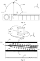
- FIG. 1 schematically illustrates a welding equipment 1 equipped with a welding device 10 according to one embodiment of the invention.
- the welding equipment 1 further comprises an enclosure 2 enveloping the welding device 10 and a frame 3.
- the welding equipment 1 can be installed in a workshop and rest on the ground via its frame 3.
- the welder 10 is an electron beam welder. That is to say, it is capable of projecting a beam of electrons FE onto a part to be welded in order to melt it locally.
- the electron beam is a stream of electrons that is projected onto the part to be welded.
- the energy dissipated by the impact of the electrons on the part to be welded causes heating and therefore the local melting of the material.
- the power of the welding device is particularly suitable for welding metal parts, for example parts made of niobium, copper, aluminum or any other type of metal.
- the welding device 10 is suitable for welding two parts 20A, 20B having a central opening 21 by being introduced inside this central opening.
- the two parts 20A, 20B are welded to each other by means of a weld bead 22 formed at their interface 23.
- the interface 23 designates the joint or in other words the junction line separating the two parts 20A, 20B. This interface 23 corresponds to an inner perimeter of the two parts when this interface is circular.
- Electron beam welding requires the electron beam to propagate in a vacuum.
- the enclosure 2 can therefore close hermetically around the parts to be welded and the device to be welded and a vacuum pump can then create a vacuum in the enclosure.
- An order of magnitude of the depression level reached in the enclosure may for example be between 10 ⁇ 2 mBar and 10 ⁇ 6 mBar.
- the two parts 20A, 20B can be of any kind.
- the two parts can be cells, half cells, or an assembly of cell elements intended to form a particle accelerating cavity. They can be made of niobium.
- the welding of two halves of cells makes it possible to obtain a cell as represented schematically and by way of example on the figure 1 . Such cells can be assembled in series to form a cavity equipping a particle accelerator.
- the assembly formed by the two cell halves 20A, 20B has the shape of an ellipsoid of revolution and the weld bead 22 is established at the height of the largest interior perimeter of the cell.
- the shape of the parts could be different, in particular they could be simply tubular.
- the two parts to be welded could not be parts of revolution or at least the interface 23 between the two parts 20A, 20B could not draw a circle.
- the distance traveled by the electron beam before impacting the two parts to be welded could be variable depending on the orientation of the parts to be welded.
- a part with a variable radius could be welded by modifying the operating parameters of the electron beam.
- the welding device 10 comprises in particular an electron gun 11, a focusing means 12 and an arm 13.
- the arm comprises in particular a means 14 for transforming the electron beam and a means 15 for deflecting the electron beam.
- the electron gun 11, the focusing means 12, the transformation means 14 and the deflection means 15 are arranged in this order following the path of the electron beam FE.
- the electron gun 11 is a means capable of generating the electron beam FE. It may in particular comprise a cathode 111, an anode 112, and optionally a wehnelt 114 interposed between the cathode and the anode.
- the cathode is capable of emitting electrons. It can for example be in the form of a filament or a massive or hollow emitting part. For example, electrons can be extracted from a hot thermal or gaseous cathode.
- the wehnelt makes it possible to regulate the quantity of electrons emitted by the cathode.
- the voltage difference between wehnelt and cathode makes it possible either to block the electrons and to prevent the emission of the electron beam, or to allow part or all of the flow of electrons emitted by the cathode to pass.
- the anode is capable of attracting electrons by virtue of an electrical voltage U applied between the cathode and the anode.
- the electrical voltage U between the anode and the cathode can for example reach a value of the order of several tens of kilovolts.
- the welding equipment therefore comprises an electric power supply means 113 which can be connected to an electricity distribution network.
- the anode, the wehnelt and the cathode can be assembled so as to be mechanically aligned along a first axis Z.
- the electrical voltage is less than or equal to 80 kV, preferably less than or equal to 60 kV, or even less than or equal to 45 kV.
- the welding device therefore requires a relatively low voltage compared to other electron beam welding devices of the state of the art.
- the use of a lower electrical voltage has many advantages, including a lower generation of X-rays, which therefore requires simpler protections for operators working with this welding equipment 1.
- a lower voltage makes the electron beam easier to deflect, which makes it possible to envisage a miniaturization of the elements constituting the welding device 10, in particular a miniaturization of the transformation means 14 and of the deflection means 15.
- the beam electrons could be generated differently, for example by means of a plasma cathode where the electrons are extracted from a plasma.
- the focusing means 12 is clearly visible on the picture 3 . It is able to focus the electron beam from the electron gun 11 along the first axis Z. More particularly the focusing means is capable of transforming a diverging upstream electron beam into a downstream converging electron beam, while maintaining the symmetry of revolution of the beam.
- the focusing means may in particular comprise a coil 121 arranged around the first axis Z.
- a coil is a solenoid, or in other words a set of turns capable of being traversed by an electric current.
- the coil 121 may comprise a magnetic core of annular shape having the Z axis as axis of revolution. When an electric current flows through the coil, a magnetic field appears.
- the field lines can be substantially oriented parallel to the axis of the coil, i.e. to the Z axis.
- the field magnetic produced by the coil exerts a force on the electrons which changes their trajectory.
- the magnetic field generated by the coil 121 can thus focus the electric beam towards a focusing point PF downstream of the focusing means.
- This focal point PF is illustrated in particular on the picture 2 .
- the focal point is positioned on the Z axis.
- the distance from the focal point to the coil 121 depends in particular on the electrical voltage U and the current flowing in the coil 121.
- the focal point PF can thus be adjusted and be positioned upstream of the transformation means 14 or downstream of the transformation means 14 or in any intermediate position.
- the electron gun 11, the focusing means 12 (as well as the deflection means 17 which will be presented later) can be grouped together in a casing 4 (or in other words a casing) integral with the frame 3.
- This casing 4 comprises a face of reference 5, substantially perpendicular to the Z axis and from which the arm 13 extends.
- the arm 13 extends parallel to the first axis Z from the reference face 5. It therefore comprises a first end 131 fixed to the housing 4 and a second end 132 free. By convention, “back” designates the side of the first end and “front” designates the side of the second end.
- the arm 13 comprises a tubular part 19 inside which the electron beam propagates.
- the tubular part 19 separates the welding device into two parts.
- a first part outside the arm 13 and illustrated on the picture 3 notably includes the electron gun 11 and the focusing means 12.
- a second part, integrated into the arm 13 and illustrated on the figure 4 comprises in particular the transformation means 14 and the deflection means 15.
- the arm 13 generally comprises the shape of a cylinder.
- This cylinder can have a diameter (indicated by D1 on the figure 1 ) less than or equal to 80mm, in particular less than or equal to 70mm, preferably less than or equal to 55mm.
- the terms “upstream” and “downstream” are defined in this document by following the direction of propagation of the electrons, the electrons propagating from upstream to downstream.
- a functional length L1 of the arm along the Z axis can be defined as the distance between the reference face 5 and the X axis along which the electron beam is deflected by the deflection means 15.
- the functional length L1 can be greater than or equal to 200 mm, in particular greater than or equal to 400 mm, preferably greater than or equal to 600 mm, or even greater than or equal to 700 mm.
- the arm 13 is intended to be introduced inside the assembly formed by the two parts of revolution 20A, 20B so as to produce the weld bead 22 along an inner perimeter, at the interface between the two parts 20A, 20B.
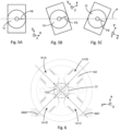
- the orientation of the welding equipment can be chosen so that the X axis is a horizontal or substantially horizontal axis.
- the welding equipment can advantageously comprise a connection in rotation around the axis Z between the device to be welded and the frame 3. This connection in rotation makes it possible to more or less tilt the axis X along which the beam of electrons exit the welder relative to the horizontal.
- the X axis along which the electron beam is emitted from the welding device can thus form a zero angle (as illustrated in the figure 5A ), a positive angle (as shown in the figure 5B ), or a negative angle (as shown in the Fig.
- the Z axis can be horizontal or vertical.
- a horizontal positioning of the Z axis makes it possible to limit the vertical size of the welding equipment 1, which is particularly useful when the arm 13 is long or when it is sought to weld a set of particularly long parts of revolution.
- the means 14 for transforming the electron beam FE is capable of varying (or in other words "modifying” or “changing") the density distribution of the electron beam in a plane perpendicular to the first axis Z.
- the transformation means 14 is capable of varying the density distribution of the electron beam along the second axis X and along the third axis Y.
- the density distribution of the beam can be modified on command.
- the beam can be either very intense or more spread out and of lower energy density.
- Each part of the beam can undergo a different angular deviation along the X axis and/or along the Y axis, which can lead either to an increase in the density or to a decrease in the density of the electron beam. Part of the beam may thus become convergent while another part of the electron beam may become divergent.
- the transformation means 14 could vary the density distribution of the electron beam only along one of these two X or Y axes, or even along any axis, perpendicular to the Z axis, which does not is not necessarily the X axis or the Y axis.
- the transformation means 14 can modify the density distribution of the beam without deviating its overall trajectory.
- the beam remains generally oriented parallel to the Z axis downstream as well as upstream of the transformation means 14.
- the transformation means 14 is not a simple mask which would block part of the electron beam and which could then warm up strongly.
- the overall power of the electron beam is substantially identical upstream and downstream of the transformation means.
- the density distribution of the electron beam designates not only the shape of a section of the beam in a plane perpendicular to the Z axis but also the distribution of the electrons inside this shape.
- the means of transformation 14 can modify a beam of electrons FE of circular section and with a uniform distribution of the electrons crossing the circular section into a beam of electrons of ovoid or elongated section with also a uniform distribution of the electrons crossing the ovoid or elongated section.
- the means of transformation 14 can modify a beam of electrons FE of circular section and with a uniform distribution of the electrons crossing the circular section into a beam of electrons of section also circular but with a distribution or a distribution of non-uniform electrons (for example with a greater proportion of electrons crossing a first half of the section than of electrons crossing the second half, complementary to the first half).
- the transformation means can modify both the orientation of the electrons making up the electron beam, the shape of the section of the electron beam and the distribution of the electrons inside this section.
- the transformation means 14 comprises at least two coils, preferably at least four coils, in particular at least six coils, or even any even number of coils.
- the coils include a magnetic axis substantially perpendicular to the Z axis and are evenly distributed around the Z axis so as to produce alternating North magnetic poles and South magnetic poles.
- the magnetic axes of the various coils are advantageously included in the same plane perpendicular to the axis Z.
- the transformation means therefore comprises a given number of pairs of coils.
- the two coils of the same pair are positioned opposite each other, along an axis perpendicular to the Z axis.
- the two coils of the same pair are therefore not positioned one behind the other along the Z axis.
- the transformation means 14 is a quadrupole. It comprises four coils 141A, 141B, 141C, 141D which are identical and arranged globally according to a rotational symmetry at 90°.
- the magnetic axes of the two coils 141A and 141C are merged into a single axis AM1.
- the magnetic axes of the two coils 141B and 141D coincide in the same axis AM2, perpendicular to the axis AM1.
- the same electric current successively passes through the coils 141A, 141B, 141C and 141D.
- These four coils therefore comprise a single electric wire conducting the current successively in these four coils.
- each coil 141A, 141B, 141C, 141D further comprises a magnetic core 142 which may have at least locally the shape of an arc of a circle or of a hyperbola.
- the magnetic core comprises a body, for example of cylindrical or profiled shape, arranged inside each coil and a head oriented towards the inside of the transformation means.
- An inscribed circle CI can be drawn passing through the top of each head of the four magnetic cores.
- the ratio of a radius of curvature of the head of the magnetic cores to the radius of the inscribed circle CI can be between 1 and 1.3 inclusive.
- the magnetic core makes it possible to guide the magnetic field lines 143 produced by the four coils 141A, 141B, 141C, 141D.
- the magnetic field lines 143 are also shown on the figure 6 . They are in the form of curved lines with an incidence perpendicular to the heads of the magnetic cores. The magnetic field lines start from the two heads of the magnetic cores of the North Poles and are directed towards the two heads of the magnetic cores of the South Poles.
- the AM1 axis or the AM2 axis can be parallel to the X axis or parallel to the Y axis, or, as shown in the figure 6 form an angle substantially equal to 45° with the X axis and with the Y axis.
- the two axes AM1 and AM2 could not be perpendicular.
- the use of a quadrupole makes it possible to vary the density distribution of the electron beam along two distinct axes.
- the transformation means does not understood that two poles one could all the same vary the density distribution according to an axis perpendicular to the axis Z.
- the means of transformation could be carried out by a single coil whose axis would be parallel to the Z axis, the electron beam passing through the center of this single coil. This single coil would therefore act as a second focusing means. This second focusing means would therefore be housed inside the arm (unlike focusing means 12). Such a single coil would also make it possible to vary the density distribution of the electron beam.
- the deflection means 15 is particularly illustrated in the figure 7 and also partially visible on the figures 8 to 11 . It is capable of deflecting the electron beam FE from an orientation parallel to the Z axis upstream of the deflection means to an orientation parallel to the X axis downstream of the deflection means. The electron beam therefore undergoes a deviation substantially equal to 90° between the upstream and the downstream of the deflection means.
- it comprises a single coil 151 whose magnetic axis is substantially parallel to the Y axis. The coil is therefore capable of producing a magnetic field oriented at least locally parallel to the Y axis when it is is carried by an electric current.
- the deflection means can also be qualified as a dipole.
- the coil 151 is positioned substantially at the free end 131 of the arm 13, in the extension of the path of the electron beam along the Z axis and behind the X axis.
- the coil 151 is positioned in the extension of the Z axis, in the half-space defined by the plane perpendicular to the Z axis containing the X axis, this half-space comprising the free end 132 of the arm 13.
- the coil 151 is therefore not crossed by the electron beam.
- the current flowing through the coil 151 can be adjusted as a function of the electric voltage U so as to produce a deflection angle equal to or substantially equal to 90°.
- a 90° deflection of the electron beam makes it possible to orient the electron beam in a direction normal to the surfaces to be welded.
- a normal incidence of the beam makes it possible to obtain the smallest possible surface impact zone.
- the current flowing in the coil 151 it is possible to vary the angle of deviation around the angle of 90°. It is thus possible to generate an oscillation or a vibration of the electron beam on either side of the interface 23 between the two parts to be welded. Such oscillation can sometimes be useful for stirring the weld pool and make the molten part more homogeneous, as well as to obtain the smoothest possible weld bead surface condition.
- the deflection means 15 comprises a magnetic core 152 arranged inside the coil 151, a first metal plate 153 bonded to the magnetic core 152 and a second metal plate 154 bonded to the magnetic core.
- the two plates 153, 154 are connected to the magnetic core 152 via two pole flanks 158. These pole flanks 158 are in contact both with the magnetic core 152 and with the plates 153, 154.
- a field line 157 produced by the coil 151 is notably illustrated on the figure 7 : it successively passes through the magnetic core 152, a first pole flank 158, the first plate 153, the air gap EF, the second plate 154, and the second pole flank 158.
- the first plate 153 and the second plate 154 are arranged symmetrically on either side of the electron beam FE, i.e. on either side of the Z axis. They both extend in a plane parallel to the X and Z axes and are spaced by an air gap EF in which the electron beam passes. They are positioned in front of the coil 51 along the Z axis.
- the two plates 153, 154 have a curved quarter-circle shape that can be distinguished on the figure 4 , 9 and 11 . More specifically, these plates may have the shape of a portion of a ring, but alternatively they could have a different shape.
- the two plates 153, 154 each have an entrance face 155 and an exit face 156.
- the entrance faces are the sides of the two plates 153, 154 which face the incident electron beam.
- the output faces are the sides of the two plates 153, 164 which face the electron beam emerging from the deflection means 15.
- the input and output faces can be defined in the thickness of the two plates 153, 154.
- the input faces 155 of the two plates form an angle A1 with the axis X.
- the angle A1 can be between 15° and 40° inclusive, preferably between 25° and 35° inclusive, or even between 28° and 33° inclusive.
- the exit faces 156 of the two plates form an angle A2 with the Z axis.
- the angle A2 can be between 0° and 15° inclusive, preferably between 5° and 12° inclusive.
- angles A1 and A2 play an important role in the quality of the deflection of the electron beam produced by the deflection means 15. These angle values A1 and A2 make it possible to obtain a deflection substantially at 90° of the beam of electrons FE while minimizing the modifications of its distribution of density. With such values of angles A1 and A2, a good compromise is obtained between, on the one hand, a sufficiently large active surface of the two plates 153, 154 and, on the other hand, a focusing effect of the magnetic field linked to edge effects. of the two plates 153, 154 well mastered.
- the entry face 155 and the exit face have sufficiently large dimensions for the electron beam to be bathed in a regular and homogeneous magnetic field.
- the plates 153, 154 are arranged along the curvature which the electron beam follows when it is deflected by the deflection means. These plates 153, 154 make it possible to guide and concentrate the magnetic field produced by the coil 151 along the path followed by the electron beam. With this arrangement of the deflection means 15, the magnetic field produced by the coil 151 is effectively concentrated in an area useful for deflecting the electron beam.
- the single coil 151 could be replaced by two separate coils, each of these two coils being joined laterally to the two plates 153, 154.
- such an embodiment could lead to magnetic field leakage.
- the welding apparatus also comprises a videoscope 16, or camera, to observe the place of impact of the electron beam FE on the part to be welded.
- the videoscope 16 makes it possible in particular to check the appearance of the weld bead. It can be connected to an observation screen positioned outside the enclosure 2.
- the videoscope extends inside the arm 13 substantially along an axis parallel to the Z axis, i.e. say parallel to the flow of electrons FE before it reaches the deflection means 15. It comprises an optical cell 161 which makes it possible to capture images in a direction parallel to the X axis and a lighting means 162 to observe welding in the best possible light conditions.
- the videoscope is retractable, or in other words telescopic, parallel to the Z axis.
- the videoscope is then located inside a volume defined by the projection of the deflection means 15 along the Z axis.
- X of the deflection means 15 is greater than the size along this same axis of the other elements 14, 18, 31, 32, 33 which equip the arm 13.
- the coil 151 as well as the two plates 153, 154 are the the largest elements of the arm 13 and they condition the value of the diameter D1.
- the videoscope By positioning the videoscope along the elements 14, 18, 31, 32, 33, and behind the two plates 153, 154, it fits into the arm 13 without increasing its diameter.
- the axis along which the electron beam FE is established along the arm 13 is offset by a value D2 with respect to the axis of revolution Z1 of the cylindrical envelope of the arm.
- This arrangement makes it possible to keep a small diameter of the arm D1. Consequently, the arm 13 can be introduced inside parts of revolution whose inside diameter is small.
- the optical cell 161 coincides with an opening through which the electron beam can be emitted out of the welding apparatus. This opening is as small as possible so that the metallic pollution released by the welding process does not reach the magnetic poles or the videoscope.
- the videoscope could not be retractable and in this case, it is the parts welded to each other which could be moved to be in the field of vision of the optical cell 161.
- This variant would nevertheless require a cover or shutter to protect the videoscope during welding.
- the videoscope could be positioned at the front end of the arm.
- the welding equipment is used to weld cells comprising an opening whose diameter is just greater than the diameter of the arm, the videoscope could be protected by positioning itself at the level of this opening, or even beyond this opening, when the electron beam is active. In this configuration, there would be no need for a specific mobile cover to protect the videoscope.
- the videoscope When it is desired to use the videoscope to observe the weld, the videoscope deploys forward between the first plate 153 and the second plate 154 as is visible on the figure 12 .
- the electron beam is then interrupted to not damage the videoscope.
- the videoscope makes it possible to observe the weld bead 22 with the same incidence as the electron beam, that is to say with an incidence normal to the weld bead and without having to move the parts to be welded.
- the forward and backward translational movement of the videoscope can be obtained for example with a cylinder and automatically, without the need to manually intervene on the welding device and therefore without breaking the vacuum. prevailing in the enclosure 2.
- the translation movement of the videoscope can be limited by a stop element, thus ensuring a reproducible positioning of the videoscope and therefore a precise adjustment of the beam on the interface to be welded.
- the welding apparatus further comprises means for centering the electron beam.
- the centering means makes it possible in particular to center the electron beam between the two plates 153, 154 of the deflection means.
- the centering means comprises means 17 for deflecting the electron beam and means 18 for detecting the position of the electron beam.
- the deflection means 17 is positioned directly downstream of the focusing means 12 while the detection means 18 is positioned upstream of the transformation means 14. Between the deflection means and the detection means 18 is the tubular portion 19, clearly visible on the figure 1 , inside which the electron beam passes.
- the deflection means 17 is capable of deflecting the electron beam by a small angle with respect to the Z axis (for example of the order of one or two degrees), and with great precision (for example of the order of 0.01°) to ensure that the electron beam can pass through a passage hole of small diameter (for example 10 mm in diameter), at a high distance from the means of the focusing means (for example of the order of 600mm).
- the electron beam can be deflected along the X axis and along the Y axis.
- the deflection means comprises for this purpose two coils 171, 172 concentric and arranged around the Z axis. These two coils 171, 172 are particularly visible on the picture 3 .
- a first coil 171 is configured to deflect the electron beam along the X axis and the second coil 172 is configured to deflect the electron beam along the Y axis.
- the first coil 171 is arranged so as to produce a field magnetic parallel to the Y axis and the second coil 172 is arranged so as to produce a magnetic field parallel to the X axis.
- these two coils could be arranged differently.
- the first coil 171 could be arranged so as to produce a magnetic field parallel to the X axis and the second coil 172 could be arranged so as to produce a magnetic field parallel to the Y axis.
- the detection means 18 comprises four electrodes 181, 182, 183, 184 arranged on the four sides of a square around the passage channel of the electron beam, that is to say around the axis Z.
- the four electrodes can be substantially identical to each other. They are positioned in rotational symmetry at right angles.
- the first electrode 181 and the second electrode 182 comprise an edge facing each other and parallel to the Y axis.
- the third electrode 183 and the fourth electrode 184 comprise an edge facing each other and parallel to the X axis.
- the arrangement of the four edges of the electrodes could deviate from a square shape, for example rather follow the shape of a rectangle while remaining within the scope of the invention.
- Each electrode is capable of detecting contact with the electron beam.
- each electrode can be connected by an electrical connection to an electronic control unit 185.
- This electronic control unit 185 is also connected to the deflection means 17 and can implement a method for adjusting or centering the electron beam which will be detailed later.
- the electrodes 181, 182, 183, 184 can have a substantially trapezoidal shape and be massive enough to withstand contact with the electron beam, even at full power, without generating excessive heating.
- the mass of the electrodes makes it possible to reduce the rise in temperature as much as possible and therefore makes it possible to preserve these electrodes.
- the trapezoidal shape makes it possible to use the maximum volume available within the limits of the cylindrical envelope of the arm 13.
- the large base of the trapezoidal shape could even have a curved shape marrying the cylindrical envelope of the arm. All four electrodes can be grounded during the welding process.
- the deflection means 17 could be simplified and only be capable of deflecting the electron beam along a single axis perpendicular to the Z axis.
- the detection means could then comprise only two electrodes arranged to detect a deflection of the electron beam. It would thus already be possible to adjust the position along an axis perpendicular to the Z axis, for example along the X axis or along the Y axis.
- the deflection means 17 could be replaced by an articulation, advantageously motorized, of the assembly formed by the electron gun 11 and the focusing means 12. This would avoid deflecting the electron beam via the deflection means 17. Consequently, the aberrations or distortions of the electron beam caused by its deflection would be avoided. Such an assembly could therefore make it possible to further increase the precision of the electron beam but the centering procedure would be slower.
- This articulation could be in the form of a plate mounted in sliding connection along the X axis and/or along the Y axis. Such a plate would make it possible to translate the electron beam parallel to the X axis and/or to the Y axis.
- the focusing means 12, the deflection means 17, the detection means 18, the transformation means 14 and the deflection means 15 are means distinct from each other. They are arranged in the order mentioned following the path of the electron beam. These means are mechanically centered with respect to each other, that is to say that the centers of these various elements or means are aligned and merged with the Z axis. As a variant, certain positions could be inverted.
- the deflection means 17 could be positioned upstream of the focusing means 12.
- the transformation means 14 could be positioned upstream of the detection means 18.
- the welding device may further comprise various elements or equipment interposed between the means 12, 14, 15, 17 and 18.
- the welding device comprises a protective diaphragm 31.
- the protective diaphragm is a solid ring comprising a central opening allowing the electron beam to pass when it is sufficiently well centered.
- the electron beam strikes the solid part of the protective diaphragm designed to withstand high-energy impacts. This prevents the electron beam from striking a more sensitive element of the welding device.
- the protective diaphragm 31 is positioned in front of the detection means 18, just after the tubular portion 19.
- the welding device also comprises a magnetic field blocking element 32 interposed between the transformation means 14 and the deflection means 15.
- the magnetic field blocking element is also in the form of a solid ring having a central opening through which the electron beam passes.
- the dimensions of this element 32 are determined to magnetically insulate the transformation means 14 from the deflection means 15.
- the magnetic field blocking element 32 is surrounded by an aluminum body 33 cooled by a cooling system comprising pipes.
- such a magnetic field blocking element could be located between any two other means of the device to be welded, for example between the focusing means 12 and the deflection means 17, or even not be used to simplify the device. welding.
- the welding device further comprises a heat shield cooled by the cooling system, this heat shield is positioned in front of the coil 151 of the deflection means 15.
- this part hits the heat shield instead of hitting the coil 151 positioned behind the heat shield.
- the welding device also includes a protective cover (not shown).
- the protective cover is positioned in such a way as to collect the metal projections from the parts to be welded. Indeed, under the impact of the electron beam, particles metals from the parts to be welded can evaporate and then attach themselves to the welding device or to other parts of the parts to be welded.
- the protective cover therefore serves to prevent these projections from damaging the deflection means 15 or the parts to be welded. When worn, the protective cover can easily be replaced without having to change the deflection means.
- the protective cover is integrated into the cylindrical profile of the arm, plumb with the two plates 153, 154 along the axis X. Thus, the integration of the protective cover does not increase the diameter of the arm.
- two parts 20A, 20B are positioned in the welding equipment so that the interface 23 between these two parts is opposite the output of the electron beam.
- This interface 23 corresponds to an inner perimeter of the assembly formed by the two parts to be welded. All of the two parts of revolution intended to be welded to each other are inserted around the arm 13 of the welding device.
- the two parts to be welded can be held by a gripping device.
- the gripping device comprises a means of connection in rotation to rotate the assembly of the two parts to be welded during the welding process.
- the assembly obtained is illustrated schematically on the figure 15 .
- the enclosure is then closed again and a vacuum is created in the enclosure.
- the welding apparatus can be energized so as to obtain an FE electron beam.
- the electron beam is not necessarily centered, i.e. the center of the electron beam may not pass through the center of the transformation means 14.
- the electron beam Prior to the actual welding operation, the electron beam can be centered. This operation consists in determining the position of the edges of the electron beam and in deducing therefrom an offset value of the electron beam by following several steps.
- the deflection means 17 is controlled so as to obtain a step of oscillating deflection of increasing amplitude of the electron beam along the X axis, for example a sinusoidal deflection.
- a sinusoidal current of increasing amplitude will be able to flow in the first coil 171.
- the electron beam then oscillates in a first plane, parallel to the axes X and Z, around its original position FE0. This first plane is delimited on either side by the first electrode 181 and the second electrode 182.
- the deflection amplitude increases with time, the electron beam ends up touching one of the two electrodes 181, 182, for example the first electrode 181.
- the contact of the electron beam on the electrode 181 is detected by the electronic control means 185.
- the deflection amplitude is then fixed at the value reached at the moment of contact of the electron beam on the first electrode 181.
- a third step the sinusoidal deflection of the electron beam is continued along the X axis but still maintaining a constant deflection amplitude, that which was fixed in the previous step.
- the electron beam always oscillates in the foreground.
- a first offset increasing with time is then applied to the electron beam to progressively shift it towards the electrode opposite to that which has been touched by the electron beam, that is to say the second electrode 182 in this example.
- the electron beam ends up touching this second electrode 182 with the same amplitude as during the contact on the first electrode 181.
- the contact of the beam of electrons on the electrode 182 is detected by the electronic control means 185.
- the value of the offset OF1 applied to the electron beam is then noted.
- a fifth step the actual centering of the electron beam is carried out. Starting from the initial position of the beam FE0, an offset corresponding to the value of the offset OF1 previously noted is applied to it. divided by two. An electron beam centered along the X axis is thus obtained between the two electrodes 181 and 182.
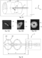
- FIG 14 shows it possible to clearly visualize the centering process.
- the position of the electron beam FE relative to the X axis is observed as a function of time.
- the two electrodes 181 and 182 are schematized by dark bands at the top and bottom of the graph.
- the curve FEmoy represents the average position of the electron beam relative to the axis X around which the sinusoidal deflection is applied .
- OF1 designates the value of the offset recorded during the fourth step.
- X0 designates the shift along the X axis which will be applied to the electron beam to center it between the two electrodes 181 and 182.
- the centering of the electron beam along the Y axis can affect the centering along the axis X carried out previously, in particular in the event of a lack of squareness of the coils 171, 172 of the deflection means.
- the centering along the X axis and along the Y axis can be repeated a second time, or even a greater number of times in order to center the electron beam by successive iterations. This centering process is completely automatic and does not require manual intervention on the welding device, nor breaking the vacuum prevailing in the enclosure 2.
- the electron beam centering operation can be performed at low power so that the electron beam does not risk damaging or marking the two parts to be welded.
- a mask could be used to prevent the electron beam from reaching the parts to be welded during the centering process which has just been described.
- the deflection amplitude of the electron beam could oscillate not in a sinusoidal shape but in a triangular shape, a crenellated shape, or any other form of alternation producing a symmetrical pattern.
- the centering could also be carried out using a martyr target instead of the parts to be welded.
- a voluntary offset or decentering can also be applied to deliberately shift the electron beam but in a controlled and reproducible manner.
- a step of calibrating the transformation means is carried out to produce an electron beam comprising a predefined density distribution at the output of the welding device. Indeed, particular density distributions may be desired to achieve different welding steps.
- the density distribution can be adjusted thanks to the transformation means 14 but also thanks to the focusing means 12. By adjusting the currents flowing through the respective coils of these two means 12, 14, it is possible to modify the density distribution of the beam.
- the focal point PF is located upstream of the transformation means, the incident electron beam in the transformation means 14 is diverging, the current variations through the coils 141A, 141B, 141C and 141D produce a first geometric modification of the density distribution of the electron beam.
- the incident electron beam in the transformation means 14 is converging, the current variations through the coils 141A, 141B, 141C and 141D produce a second geometric modification of the density distribution of the electron beam, different from the first geometric modification.
- the current flowing in the coil 121 and the current flowing in the four coils 141A, 141B, 141C and 141D therefore constitute two adjustment parameters on which an operator can rely to achieve varied density distributions.
- the density distributions obtained can have a symmetry of revolution or be more or less elongated parallel to the interface 23 or perpendicular to the interface 23.
- the density distribution can thus have a circular shape but also an elongated ovoid shape along the Z axis or elongated along the Y axis or even elongated along any axis perpendicular to the X axis.
- the deflection means 15 disturbs the density distribution of the electron beam obtained directly at the output of the transformation means 14. Indeed, the 90° deflection of the electron beam by the deflection means inexorably causes a modification of the distribution density of the electron beam. It is therefore necessary to anticipate, at the transformation means 14, the deformations produced by the deflection means 15 in order to obtain a predefined density distribution at the output of the welding device.
- THE figures 15A, 15B and 15C illustrate different forms of projection of the electron beam on the two parts to be welded. These representations come from test results of the welding device 10. They can in particular be obtained with an electron beam analyzer.
- the calibration step can be defined so as to produce an electron beam whose density is distributed parallel to the interface between the two parts of revolution.
- This shape is particularly suitable for carrying out the actual welding operation. Indeed, too high an energy density could lead to a weld with projection of material, which is detrimental to the quality of the finished part.
- the electron beam can then melt the metal, in this case niobium, on either side of the junction line between the two parts of revolution. The width of the weld bead thus obtained can be very small. Welding is achieved by the keyhole effect.
- the power sent is such that material is evaporated at the interface between the two parts to be welded and a hole of the desired depth is created.
- This (key)hole is then moved (or in other words “pulled") on the part by the rotation of the assembly formed by the two parts to be welded.
- the material forming the two parts to be welded is melted, which forms a liquid pool.
- This bath solidifies when the electron beam moves away from this zone, which is why this bath has a roughly keyhole shape.
- a reduction in power and/or a modification of the focusing of the electron beam make it possible to raise the hole to the surface (i.e. gradually decrease the depth of the hole) of the two parts welded together and to obtain a smooth bead.
- the electron beam can melt the metal to a depth for example of the order of 2mm to 3mm, or even to an even greater depth.
- the metal could be melted over the entire thickness of the two parts to be welded.
- the electron beam does not completely cross the thickness of the two parts to be welded.
- the metal is not melted over the entire thickness of the two parts to be welded.
- the welding equipment can advantageously comprise a motor connected to a means for gripping the parts to be welded, such as for example a chuck.
- the welding device remains stationary during welding.
- the speed of rotation of the assembly formed by the two parts to be welded can be adjusted according in particular to the power of the electron beam and the nature of the parts to be welded.
- the position of the focusing point PF can be adjusted to obtain a more or less distant focusing of the electron beam after deflection. This can in particular be useful for welding two parts whose interface is not a circle centered on the Z axis without having to move the two parts to be welded relative to the welding equipment.
- the calibration step can also be defined to produce an electron beam whose density is distributed perpendicular to the interface formed between the two parts of revolution.
- This beam shape is particularly advantageous for smoothing a weld bead previously formed between the two parts.
- the calibration step can also be defined to produce an electron beam whose density is distributed in a circular and uniform manner.
- an extremely concentrated electron beam making it possible to achieve extremely high powers per unit area.
- U between the anode and the cathode equal to 55kV
- a current flowing from the anode to the cathode equal to 50mA
- a circular or point density distribution can be particularly useful for carrying out a local treatment of a part, such as for example the repair of a defect such as a hole, a lack of material, or surface irregularities.
- the power of the electron beam can then possibly be lowered to avoid material projections.
- the density distribution of the electron beam is adapted to the desired effects for producing the weld bead.
- the great length L1 of the arm 13 makes it possible to envisage welding a set of cells to each other by limiting the number of manipulations and avoiding undoing the vacuum prevailing in the enclosure.
- the cells can be positioned against each other beforehand and held in position by specific tools.
- the welding device can successively weld the interfaces between two adjacent cells.
- the set of cells is translated along the Z axis between each welding operation so as to weld all the interfaces between the cells.
- a sliding carriage housed inside the enclosure makes it possible to automatically move the set of cells.
- the arm 13 can be inserted on one side or the other of the set of cells to be welded, it is possible to weld a set of cells whose total length reaches the length of the arm 13 multiplied by two.
- the welding station can also be equipped with a turning device capable of pivoting all the cells by 180° so as to insert the arm 13 successively through the two opposite openings of the set of cells.
- the 180° pivoting of all the cells can be carried out manually by breaking the vacuum in the enclosure.
- only an interruption of the vacuum prevailing in the enclosure would be necessary to weld all the cavities.
- the use of the welding equipment according to the invention therefore makes it possible to avoid too frequent interruption of the vacuum in the enclosure. In particular, an interruption is not necessary to weld each cell or subset of cells.
- the invention it is therefore possible to weld a set of cells whose length is 1200 mm, or even 1300 mm, or even an even longer length with a minimum of handling and with a very high level of quality of the weld bead.
Landscapes
- Engineering & Computer Science (AREA)
- Mechanical Engineering (AREA)
- Welding Or Cutting Using Electron Beams (AREA)
Description
L'invention concerne un appareil à souder par faisceau d'électrons comme défini dans le préambule de la revendication 1 (voir, par exemple,
Pour l'assemblage par soudure de deux pièces, plusieurs techniques sont aujourd'hui disponibles. Parmi ces techniques, le soudage par faisceau d'électrons est un procédé de soudage utilisant l'interaction d'un faisceau d'électrons avec les pièces à assembler. Des électrons lancés à grande vitesse dans le vide impactent les deux pièces au niveau de leur interface. L'énergie cinétique importante des électrons est alors transformée en chaleur au moment de l'impact, ce qui provoque la fusion puis le soudage des matériaux. La possibilité de concentrer le faisceau d'électrons sur une zone étroite permet d'obtenir un assemblage présentant peu de déformation et dans lequel la zone affectée thermiquement est restreinte. Cette technique est donc privilégiée pour les assemblages requérant une grande précision et une grande qualité.For the assembly by welding of two parts, several techniques are available today. Among these techniques, electron beam welding is a welding process using the interaction of an electron beam with the parts to be assembled. Electrons launched at high speed into the vacuum impact the two parts at their interface. The high kinetic energy of the electrons is then transformed into heat at the moment of impact, which causes the materials to melt and then weld. The possibility of concentrating the electron beam on a narrow zone makes it possible to obtain an assembly presenting little deformation and in which the heat-affected zone is restricted. This technique is therefore preferred for assemblies requiring high precision and high quality.
En particulier, l'assemblage par soudure de cellules en niobium constituant une cavité accélératrice de particules doit être réalisé avec le plus grand soin de manière à éviter tout défaut de la surface intérieure des cellules. En effet, de tels défauts pourraient considérablement diminuer les performances de l'accélérateur de particules.In particular, the assembly by soldering of niobium cells constituting a particle accelerating cavity must be carried out with the greatest care so as to avoid any defect in the interior surface of the cells. Indeed, such defects could considerably decrease the performance of the particle accelerator.
Les cellules constituant une cavité accélératrice de particules sont des pièces de révolution présentant une ouverture centrale traversante. Pour obtenir un état de surface aussi bon que possible pour l'assemblage de deux cellules d'une cavité accélératrice de particules, la soudure doit être réalisée de préférence par l'intérieur, c'est-à-dire que la ligne de soudure doit de préférence être établie le long d'un périmètre intérieur des cellules à assembler. L'appareil à souder nécessaire pour cette opération doit donc pouvoir être introduit par l'ouverture centrale à l'intérieur des cellules à souder. A cet effet, on connait l'usage d'appareil à souder comprenant un bras destiné à être introduit à l'intérieur des cellules. Le bras s'étend parallèlement à l'axe de révolution des cellules à souder et il se termine par un coude permettant d'orienter le faisceau d'électrons parallèlement à l'un des rayons des cellules.The cells constituting a particle accelerating cavity are parts of revolution having a through central opening. To obtain a surface finish that is as good as possible for the assembly of two cells of a particle accelerating cavity, the welding must preferably be carried out from the inside, that is to say that the welding line must preferably be established along an inner perimeter of the cells to be assembled. The soldering device required for this operation must therefore be able to be introduced through the central opening inside the cells to be welded. For this purpose, the use of a welding device comprising an arm intended to be introduced inside the cells is known. The arm extends parallel to the axis of revolution of the cells to be welded and it ends with an elbow making it possible to orient the electron beam parallel to one of the radii of the cells.
Les appareils à souder connus de l'état de la technique produisent en sortie un faisceau d'électrons mal maîtrisé. Notamment, la distribution de densité du faisceau d'électrons en sortie de l'appareil à souder peut être mal maitrisée, ce qui conduit à chauffer une zone trop large ou trop étroite au niveau de l'interface entre les deux pièces à souder. La température atteinte par le métal peut être par conséquent également mal maitrisée. Le cordon de soudure peut alors présenter des défauts de forme ou de structure. Des projections de métal peuvent également se produire lors de la soudure. Ces projections peuvent se redéposer ensuite sur les deux pièces à souder ce qui les endommage.Welding devices known from the state of the art produce a poorly controlled electron beam at the output. In particular, the density distribution of the electron beam at the output of the device to be welded can be poorly controlled, which results in heating an area that is too wide or too narrow at the level of the interface between the two parts to be welded. The temperature reached by the metal can therefore also be poorly controlled. The weld bead may then have shape or structure defects. Metal spatter can also occur during welding. These projections can then be redeposited on the two parts to be welded, which damages them.
De plus, l'axe du faisceau d'électrons peut être influencé par de nombreux paramètres de fonctionnement. L'axe du faisceau peut alors se trouver décalé par rapport à l'interface entre les deux cellules à souder ce qui provoque également un défaut de soudure.Moreover, the axis of the electron beam can be influenced by many operating parameters. The axis of the beam may then be offset with respect to the interface between the two cells to be welded, which also causes a welding defect.
Par ailleurs, les bras équipant les appareils à souder existant sont souvent volumineux. Ils ne peuvent donc pas être introduits à l'intérieur de pièces présentant une ouverture centrale de faible diamètre. Les bras peuvent également être insuffisamment long pour assembler plusieurs cellules le long de leur axe de révolution. Un faible diamètre associé avec une grande longueur du bras provoque une baisse de rigidité du bras et, généralement, un guidage dégradé du faisceau d'électrons. La réduction du diamètre du bras et l'augmentation de sa longueur apparaissent donc antinomiques de la précision du faisceau d'électrons.Furthermore, the arms equipping existing welding devices are often bulky. They therefore cannot be introduced inside parts having a central opening of small diameter. The arms can also be long enough to assemble several cells along their axis of revolution. A small diameter associated with a large length of the arm causes a drop in rigidity of the arm and, generally, a degraded guidance of the electron beam. Reducing the diameter of the arm and increasing its length therefore appear contradictory to the precision of the electron beam.
Enfin, pour le réglage des faisceaux d'électrons, de nombreuses manipulations sont généralement nécessaires. Notamment, il est souvent nécessaire d'ouvrir l'enceinte sous vide dans laquelle est placée l'appareil à souder pour inspecter les pièces ou procéder à des réglages. L'ouverture de l'enceinte détériore le vide qui y est établit. Le vide doit ensuite à nouveau être obtenu pour pouvoir procéder à une opération de soudage. Ces interventions sont donc fastidieuses et non compatibles avec une utilisation industrielle de l'équipement de soudure.Finally, for the adjustment of the electron beams, numerous manipulations are generally necessary. In particular, it is often necessary to open the vacuum enclosure in which the welding device is placed to inspect the parts or make settings. The opening of the enclosure deteriorates the vacuum which is established there. The vacuum must then be obtained again in order to be able to carry out a welding operation. These interventions are therefore tedious and not compatible with industrial use of the welding equipment.
Le but de l'invention est de fournir un appareil à souder remédiant aux inconvénients ci-dessus et améliorant les appareils à souder connus de l'art antérieur.The object of the invention is to provide a welding device remedying the above drawbacks and improving the welding devices known from the prior art.
Plus précisément, un premier objet de l'invention est un appareil à souder par faisceau d'électrons apte à produire des faisceaux d'électrons avec des distributions de densité variées et bien maitrisées.More specifically, a first object of the invention is an electron beam welding device capable of producing electron beams with varied and well-controlled density distributions.
Un second objet de l'invention est un appareil à souder par faisceau d'électrons apte à produire un faisceau d'électrons parfaitement positionné.A second object of the invention is an electron beam welding device capable of producing a perfectly positioned electron beam.
Un troisième objet de l'invention est un appareil à souder par faisceau d'électrons simple à configurer et ne nécessitant pas d'ouvrir l'enceinte dans laquelle il se trouve pour être réglé.A third object of the invention is an electron beam welding device that is simple to configure and does not require opening the enclosure in which it is located in order to be adjusted.
Un quatrième objet de l'invention est un appareil à souder par faisceau d'électrons particulièrement compact, permettant de souder par l'intérieur deux pièces comprenant une ouverture centrale de faible diamètre, les deux pièces comprenant également une grande longueur.A fourth object of the invention is a particularly compact electron beam welding device, allowing the internal welding of two parts comprising a central opening of small diameter, the two parts also comprising a great length.
L'invention se rapporte à un appareil à souder par faisceau d'électrons comprenant :
- un canon à électrons apte à générer un faisceau d'électrons,
- un moyen de focalisation apte à orienter le faisceau d'électrons selon un premier axe,
- un bras s'étendant parallèlement au premier axe, le bras comprenant :
- un moyen de transformation d'une distribution de densité du faisceau d'électrons dans un plan perpendiculaire au premier axe, et
- un moyen de déviation du faisceau d'électrons selon un deuxième axe sensiblement perpendiculaire au premier axe.
- an electron gun capable of generating an electron beam,
- a focusing means capable of directing the electron beam along a first axis,
- an arm extending parallel to the first axis, the arm comprising:
- means for transforming a density distribution of the electron beam in a plane perpendicular to the first axis, and
- means for deflecting the electron beam along a second axis substantially perpendicular to the first axis.
Le moyen de transformation peut comprendre au moins deux bobines, de préférence au moins quatre bobines, notamment au moins six bobines, les au moins deux bobines formant un axe magnétique sensiblement perpendiculaire audit premier axe, les au moins deux bobines étant réparties autour dudit premier axe de sorte à produire une alternance de pôles magnétiques Nord et de pôles magnétiques Sud.The transformation means may comprise at least two coils, preferably at least four coils, in particular at least six coils, the at least two coils forming a magnetic axis substantially perpendicular to said first axis, the at least two coils being distributed around said first axis so as to produce an alternation of North magnetic poles and South magnetic poles.
Le canon à électrons, le moyen de focalisation, le moyen de transformation et le moyen de déviation peuvent être agencés dans cet ordre en suivant le parcours du faisceau d'électrons, le moyen de focalisation comprenant une distance focale variable, le moyen de focalisation étant apte à focaliser le faisceau d'électrons en un point de focalisation positionné en amont du moyen de transformation et le moyen de focalisation étant apte à focaliser le faisceau d'électrons en un point de focalisation positionné en aval du moyen de transformation.The electron gun, the focusing means, the transforming means and the deflecting means can be arranged in this order following the path of the electron beam, the focusing means comprising a variable focal distance, the focusing means being able to focus the electron beam at a focusing point positioned upstream of the transformation means and the focusing means being able to focus the electron beam at a focusing point positioned downstream of the transformation means.
Le moyen de déviation peut comprendre une bobine apte à produire un champ magnétique orienté sensiblement perpendiculairement audit premier axe lorsque ladite bobine est parcourue par un courant électrique, ladite bobine étant positionnée sensiblement dans le prolongement du premier axe, derrière ledit deuxième axe.The deflection means may comprise a coil capable of producing a magnetic field oriented substantially perpendicular to said first axis when said coil is traversed by an electric current, said coil being positioned substantially in the extension of the first axis, behind said second axis.
Le moyen de déviation peut comprendre un noyau magnétique agencé à l'intérieur de ladite bobine, une première plaque métallique liée au noyau magnétique par un premier flanc polaire, une deuxième plaque métallique liée au noyau magnétique par un deuxième flanc polaire, la première plaque et la deuxième plaque étant agencées symétriquement de part et d'autre dudit premier axe, la première plaque et la deuxième plaque comprenant chacune une face d'entrée et une face de sortie, la face d'entrée formant avec ledit deuxième axe un angle compris entre 15° et 40° inclus, la face de sortie formant avec ledit premier axe un angle compris entre 0° et 15° inclus..The deflection means may comprise a magnetic core arranged inside said coil, a first metal plate bonded to the magnetic core by a first pole flank, a second metal plate bonded to the magnetic core by a second pole flank, the first plate and the second plate being arranged symmetrically on either side of said first axis, the first plate and the second plate each comprising an entry face and an exit face, the entry face forming with said second axis an angle between 15° and 40° inclusive, the exit face forming with said first axis an angle of between 0° and 15° inclusive.
L'appareil à souder peut comprendre un vidéoscope pour observer un impact du faisceau d'électrons, le vidéoscope s'étendant sensiblement le long d'un axe parallèle audit premier axe, le vidéoscope étant positionné à l'arrière du moyen de déviation à l'intérieur d'un volume défini par la projection du moyen de déviation selon ledit premier axe.The welding apparatus may include a videoscope for observing impact of the electron beam, the videoscope extending substantially along a parallel axis said first axis, the videoscope being positioned at the rear of the deflecting means inside a volume defined by the projection of the deflecting means along said first axis.
Le vidéoscope peut être rétractable parallèlement au premier axe, et il peut être apte à s'étendre entre la première plaque et la deuxième plaque.The videoscope can be retractable parallel to the first axis, and it can be adapted to extend between the first plate and the second plate.
L'appareil à souder peut comprendre un diaphragme de protection pour protéger un élément de l'appareil à souder du faisceau d'électrons en cas de déviation accidentelle du faisceau d'électrons,
et/ou,
- il peut comprendre un élément bloqueur de champ magnétique interposé entre le moyen de transformation et le moyen de déviation,
et/ou, - il peut comprendre un écran thermique, notamment un écran thermique refroidi par un système de refroidissement,
et/ou, - il peut comprendre un capot de protection positionné de sorte à protéger une pièce à souder et/ou un élément de l'appareil à souder de projections métalliques issues d'une pièce à souder.
and or,
- it may comprise a magnetic field blocking element interposed between the transformation means and the deflection means,
and or, - it may include a heat shield, in particular a heat shield cooled by a cooling system,
and or, - it may comprise a protective cover positioned so as to protect a part to be welded and/or an element of the device to be welded against metal projections from a part to be welded.
Le bras peut comprendre globalement la forme d'un cylindre, ledit cylindre comprenant un axe de révolution décalé d'une valeur non nulle par rapport audit premier axe, et/ou
- ledit cylindre comprenant un diamètre inférieur ou égal à 80mm, notamment inférieur ou égal à 70mm, de préférence inférieur ou égal à 60mm,
et/ou - ledit cylindre comprenant une longueur suivant ledit premier axe supérieure ou égale à 200mm, notamment supérieure ou égale à 400 mm, de préférence supérieure ou égale à 600mm.
- said cylinder comprising a diameter less than or equal to 80mm, in particular less than or equal to 70mm, preferably less than or equal to 60mm,
and or - said cylinder comprising a length along said first axis greater than or equal to 200 mm, in particular greater than or equal to 400 mm, preferably greater than or equal to 600 mm.
L'appareil à souder peut comprendre :
- un moyen de déflection du faisceau d'électrons, et
- un moyen de détection de la position du faisceau d'électrons, le moyen de détection comprenant deux électrodes agencées de part et d'autre du premier axe, chaque électrode étant apte à détecter un contact avec le faisceau d'électrons.
- means for deflecting the electron beam, and
- means for detecting the position of the electron beam, the detection means comprising two electrodes arranged on either side of the first axis, each electrode being capable of detecting contact with the electron beam.
L'appareil à souder peut comprendre :
- un moyen de déflection du faisceau d'électrons, et
- un moyen de détection de la position du faisceau d'électrons, le moyen de détection comprenant quatre électrodes agencées aux quatre côtés d'un carré autour du premier axe, chaque électrode étant apte à détecter un contact avec le faisceau d'électrons.
- means for deflecting the electron beam, and
- means for detecting the position of the electron beam, the detection means comprising four electrodes arranged on the four sides of a square around the first axis, each electrode being able to detect contact with the electron beam.
L'invention se rapporte également à un équipement de soudure comprenant un bâti destiné à reposer sur un sol et un appareil à souder tel que défini précédemment, l'appareil à souder étant mobile en rotation autour dudit premier axe par rapport au bâti.The invention also relates to welding equipment comprising a frame intended to rest on the ground and a welding device as defined above, the welding device being rotatable about said first axis relative to the frame.
L'invention se rapporte également à un procédé de soudage de deux pièces comprenant une ouverture centrale, par un faisceau d'électrons généré par un appareil à souder tel que défini précédemment ou par un équipement de soudure tel que défini précédemment, le procédé de soudage comprenant :
- une étape de positionnement des deux pièces destinées à être soudées l'une à l'autre autour du bras de l'appareil à souder,
- une étape de calibration du moyen de transformation pour produire un faisceau d'électrons comprenant une distribution de densité prédéfinie en sortie de l'appareil à souder,
- une étape de projection d'un faisceau d'électrons sur une interface formée entre les deux pièces.
- a step of positioning the two parts intended to be welded to each other around the arm of the welding device,
- a step of calibrating the transformation means to produce an electron beam comprising a predefined density distribution at the output of the welding device,
- a step of projecting an electron beam onto an interface formed between the two parts.
L'étape de calibration peut être définie pour produire un faisceau d'électrons dont la densité est distribuée soit parallèlement à une interface formée entre les deux pièces, soit perpendiculairement à une interface formée entre les deux pièces, soit de manière circulaire et uniforme, soit selon toute forme intermédiaire entre une distribution parallèle à l'interface et une distribution circulaire et uniforme, soit selon toute forme intermédiaire entre une distribution perpendiculaire à l'interface et une distribution circulaire et uniforme, et l'étape de projection peut être une étape de soudure des deux pièces, notamment une soudure de type trou de serrure, ou une étape de lissage d'une soudure, ou une étape réparation locale d'une soudure, notamment une étape de traitement de fin de cordon d'une soudure.The calibration step can be defined to produce an electron beam whose density is distributed either parallel to an interface formed between the two parts, or perpendicular to an interface formed between the two parts, or in a circular and uniform manner, or according to any intermediate shape between a distribution parallel to the interface and a circular and uniform distribution, or according to any intermediate shape between a distribution perpendicular to the interface and a distribution circular and uniform, and the projection step can be a step of welding the two parts, in particular a weld of the keyhole type, or a step of smoothing a weld, or a step of local repair of a weld, in particular a weld bead end processing step.
L'étape de calibration peut être définie pour produire un faisceau d'électrons dont la densité est distribuée perpendiculairement à une interface formée entre les deux pièces, et l'étape de projection peut être une étape de lissage d'une soudure préalablement formée entre les deux pièces.The calibration step can be defined to produce an electron beam whose density is distributed perpendicular to an interface formed between the two parts, and the projection step can be a step of smoothing a weld previously formed between the two pieces.
L'étape de calibration peut être définie pour produire un faisceau d'électrons dont la densité est distribuée de manière circulaire et uniforme, et l'étape de projection peut être une étape de réparation locale d'une soudure ou une étape de traitement de fin de cordon d'une soudure, notamment la puissance du faisceau d'électrons étant progressivement réduite jusqu'à zéro lorsque le faisceau d'électrons atteint la fin du cordon de soudure.The calibration step can be set to produce an electron beam whose density is circularly and evenly distributed, and the projection step can be a local weld repair step or an end treatment step. bead of a weld, in particular the power of the electron beam being gradually reduced to zero when the electron beam reaches the end of the weld bead.
Le canon à électrons peut comprendre une anode et une cathode, une tension électrique entre l'anode et la cathode étant inférieure ou égale à 60kV, notamment inférieure ou égale à 45kV lors de l'étape de projection.The electron gun may comprise an anode and a cathode, an electrical voltage between the anode and the cathode being less than or equal to 60 kV, in particular less than or equal to 45 kV during the spraying step.
L'invention se rapporte également à un procédé de réglage d'un appareil à souder tel que défini précédemment, le procédé de réglage comprenant :
- une étape de déflection oscillante du faisceau d'électrons, le faisceau d'électrons oscillant dans un premier plan défini entre une première électrode et une deuxième électrode du moyen de détection, la deuxième électrode étant opposée à la première électrode par rapport au faisceau d'électrons, l'amplitude de l'oscillation étant croissante avec le temps, puis
- une étape de détection d'un contact du faisceau d'électrons sur une électrode parmi la première électrode et la deuxième électrode, puis
- une étape de déflection oscillante du faisceau d'électrons, le faisceau d'électrons oscillant dans le premier plan, l'amplitude de la sinusoïde étant maintenue à la valeur atteinte au moment du contact du faisceau d'électrons sur ladite électrode, un premier offset croissant avec le temps étant appliqué sur le faisceau d'électrons pour le décaler progressivement vers l'autre électrode parmi la première électrode et la deuxième électrode, puis
- une étape de détection d'un contact du faisceau d'électrons sur ladite autre électrode, puis
- une étape de centrage du faisceau d'électrons en décalant le faisceau d'électrons vers ladite autre électrode d'une valeur égale au premier offset appliqué sur le faisceau d'électrons au moment de son contact avec ladite autre électrode divisé par deux.
- a step of oscillating deflection of the electron beam, the electron beam oscillating in a first plane defined between a first electrode and a second electrode of the detection means, the second electrode being opposite the first electrode with respect to the beam of electrons, the amplitude of the oscillation being increasing with time, then
- a step of detecting a contact of the electron beam on an electrode among the first electrode and the second electrode, then
- a step of oscillating deflection of the electron beam, the electron beam oscillating in the first plane, the amplitude of the sinusoid being maintained at the value reached at the moment of contact of the electron beam on the said electrode, a first offset increasing with time being applied to the electron beam to gradually shift it towards the other electrode among the first electrode and the second electrode, then
- a step of detecting a contact of the electron beam on said other electrode, then
- a step of centering the electron beam by shifting the electron beam towards said other electrode by a value equal to the first offset applied to the electron beam at the time of its contact with said other electrode divided by two.
Le procédé de réglage peut également comprendre :
- une étape de déflection oscillante du faisceau d'électrons, le faisceau d'électrons oscillant dans un deuxième plan défini entre une troisième électrode et une quatrième électrode du moyen de détection, la quatrième électrode étant opposée à la troisième électrode par rapport au faisceau d'électrons, le deuxième plan étant perpendiculaire au premier plan, l'amplitude de l'oscillation étant croissante avec le temps, puis
- une étape de détection d'un contact du faisceau d'électrons sur une électrode parmi la troisième électrode et la quatrième électrode, puis
- une étape de déflection oscillante du faisceau d'électrons, le faisceau d'électrons oscillant dans le deuxième plan, l'amplitude de l'oscillation étant maintenue à la valeur atteinte au moment du contact du faisceau d'électrons sur ladite électrode, un deuxième offset croissant avec le temps étant appliqué sur le faisceau d'électrons pour le décaler progressivement vers l'autre électrode parmi la troisième électrode et la quatrième électrode, puis
- une étape de détection d'un contact du faisceau d'électrons sur ladite autre électrode, puis
- une étape de centrage du faisceau d'électrons en décalant le faisceau d'électrons vers ladite autre électrode d'une valeur égale à le deuxième offset appliqué sur le faisceau d'électrons au moment de son contact avec ladite autre électrode divisé par deux.
- a step of oscillating deflection of the electron beam, the electron beam oscillating in a second plane defined between a third electrode and a fourth electrode of the detection means, the fourth electrode being opposite the third electrode with respect to the beam of electrons, the second plane being perpendicular to the first plane, the amplitude of the oscillation being increasing with time, then
- a step of detecting a contact of the electron beam on an electrode among the third electrode and the fourth electrode, then
- a step of oscillating deflection of the electron beam, the electron beam oscillating in the second plane, the amplitude of the oscillation being maintained at the value reached at the moment of contact of the electron beam on the said electrode, a second offset increasing with time being applied to the electron beam to gradually shift it towards the other electrode among the third electrode and the fourth electrode, then
- a step of detecting a contact of the electron beam on said other electrode, then
- a step of centering the electron beam by shifting the electron beam towards said other electrode by a value equal to the second offset applied to the electron beam at the time of its contact with said other electrode divided by two.
Ces objets, caractéristiques et avantages de la présente invention seront exposés en détail dans la description suivante d'un mode de réalisation particulier fait à titre non-limitatif en relation avec les figures jointes parmi lesquelles :
- La
figure 1 est une vue en coupe de dessus d'un équipement de soudure selon un mode de réalisation de l'invention. - La
figure 2 est une vue schématique de dessus de l'équipement de soudure. - La
figure 3 est une vue en coupe de dessus d'une première partie d'un appareil à souder selon un mode de de réalisation de l'invention. - La
figure 4 est une vue en coupe de dessus d'une deuxième partie de l'appareil à souder. - La
figure 5A est une vue schématique de face de l'appareil à souder, un faisceau d'électrons issu de l'appareil à souder étant orienté horizontalement. - La
figure 5B est une vue schématique de face de l'appareil à souder, le faisceau d'électrons étant légèrement incliné vers le haut par rapport à l'horizontale. - La
figure 5C est une vue schématique de face de l'appareil à souder, le faisceau d'électrons étant légèrement incliné vers le bas par rapport à l'horizontale. - La
figure 6 est une vue en coupe et de face d'un moyen de transformation de l'appareil à souder. - La
figure 7 est un plan en coupe d'un moyen de déviation de l'appareil à souder - La
figure 8 est une première vue en perspective d'une partie d'un bras de l'appareil à souder. - La
figure 9 est une première vue en perspective du moyen de déviation. - La
figure 10 est une deuxième vue en perspective de ladite partie du bras de l'appareil à souder. - La
figure 11 est une deuxième vue en perspective du moyen de déviation. - La
figure 12 est une vue en coupe de dessus de l'extrémité du bras, le bras comprenant un vidéoscope en position déployée. - La
figure 13 est une vue schématique de face d'un moyen de détection de l'appareil à souder. - La
figure 14 comprend deux graphiques illustrant un procédé de centrage du faisceau d'électrons. - La
figure 15 est une vue schématique de l'équipement de soudure lors d'une opération de soudure. - La
figure 15A est une représentation d'une première projection d'un faisceau d'électrons sur une interface entre deux pièces à souder. - La
figure 15B est une représentation d'une deuxième projection d'un faisceau d'électrons sur l'interface entre les deux pièces à souder. - La
figure 15C est une représentation d'une troisième projection d'un faisceau d'électrons sur l'interface entre les deux pièces à souder. - La
figure 16 est une deuxième vue en coupe de dessus de l'équipement de soudure.
- There
figure 1 is a top sectional view of welding equipment according to one embodiment of the invention. - There
figure 2 is a schematic top view of the welding equipment. - There
picture 3 - There
figure 4 is a top sectional view of a second part of the welding apparatus. - There
figure 5A is a schematic front view of the welding device, an electron beam from the welding device being oriented horizontally. - There
figure 5B is a schematic front view of the welding apparatus, with the electron beam angled slightly upward from the horizontal. - There
Fig. 5C is a schematic front view of the welding apparatus, with the electron beam angled slightly downward from the horizontal. - There
figure 6 is a sectional and front view of a means of transformation of the welding apparatus. - There
figure 7 is a sectional drawing of a deflection means of the welding apparatus - There
figure 8 is a first perspective view of part of a welder arm. - There
figure 9 is a first perspective view of the deflection means. - There
figure 10 is a second perspective view of said part of the arm of the welding device. - There
figure 11 is a second perspective view of the deflection means. - There
figure 12 is a top sectional view of the end of the arm, the arm comprising a videoscope in the deployed position. - There
figure 13 is a schematic front view of a sensing means of the welder. - There
figure 14 includes two graphs illustrating a method of centering the electron beam. - There
figure 15 is a schematic view of the welding equipment during a welding operation. - There
figure 15A is a representation of a first projection of an electron beam on an interface between two parts to be welded. - There
figure 15B is a representation of a second projection of an electron beam on the interface between the two parts to be welded. - There
Fig. 15C is a representation of a third projection of an electron beam on the interface between the two parts to be welded. - There
figure 16 is a second top sectional view of the welding equipment.
La
L'appareil à souder 10 est un appareil à souder par faisceau d'électrons. C'est-à-dire qu'il est apte à projeter un faisceau d'électrons FE sur une pièce à souder afin de la faire fondre localement. Le faisceau d'électrons est un flux d'électrons qui est projeté sur la pièce à souder. L'énergie dissipée par l'impact des électrons sur la pièce à souder provoque un échauffement et donc la fusion locale du matériau. La puissance de l'appareil à souder est notamment adaptée pour souder des pièces métalliques, par exemple des pièces en niobium, en cuivre, en aluminium ou en tout autre type de métal. En particulier, l'appareil à souder 10 est adapté pour souder deux pièces 20A, 20B présentant une ouverture centrale 21 en étant introduit à l'intérieur de cette ouverture centrale. Les deux pièces 20A, 20B sont soudées l'une à l'autre grâce à un cordon de soudure 22 formé au niveau de leur interface 23. L'interface 23 désigne le joint ou autrement dit la ligne de jonction séparant les deux pièces 20A, 20B. Cette interface 23 correspond à un périmètre intérieur des deux pièces lorsque cette interface est circulaire.The
La soudure par faisceau d'électrons requiert que le faisceau d'électrons se propage dans le vide. L'enceinte 2 peut donc se refermer hermétiquement autour des pièces à souder et de l'appareil à souder et une pompe à vide peut alors faire le vide dans l'enceinte. Un ordre de grandeur du niveau de dépression atteint dans l'enceinte peut être par exemple compris entre 10-2 mBar et 10-6 mBar.Electron beam welding requires the electron beam to propagate in a vacuum. The
Les deux pièces 20A, 20B peuvent être de toute nature. Avantageusement, les deux pièces peuvent être des cellules, des moitiés de cellules, ou un assemblage d'éléments de cellules destinées à former une cavité accélératrice de particules. Elles peuvent être fabriquées en niobium. La soudure de deux moitiés de cellules permet d'obtenir une cellule telle que représentée schématiquement et à titre d'exemple sur la
Selon une autre variante, les deux pièces à souder pourraient ne pas être des pièces de révolution ou tout au moins l'interface 23 entre les deux pièces 20A, 20B pourrait ne pas dessiner un cercle. Auquel cas, la distance parcourue par le faisceau d'électrons avant d'impacter les deux pièces à souder pourrait être variable en fonction de l'orientation des pièces à souder. Notamment, une pièce à rayon variable pourrait être soudée en modifiant les paramètres de fonctionnement du faisceau d'électrons.According to another variant, the two parts to be welded could not be parts of revolution or at least the
L'appareil à souder 10 comprend notamment un canon à électrons 11, un moyen de focalisation 12 et un bras 13. Le bras comprend notamment un moyen de transformation 14 du faisceau d'électrons et un moyen de déviation 15 du faisceau d'électrons. Comme cela apparait sur la représentation schématique de l'appareil à souder sur la
Le canon à électrons 11 est un moyen apte à générer le faisceau d'électrons FE. Il peut notamment comprendre une cathode 111, une anode 112, et éventuellement un wehnelt 114 interposé entre la cathode et l'anode. La cathode est apte à émettre des électrons. Elle peut par exemple se trouver sous la forme d'un filament ou d'une pièce émettrice massive ou creuse. Par exemple, les électrons peuvent être extraits d'une cathode chaude thermo-émissive ou gazeuse. Le wehnelt permet de réguler la quantité d'électrons émis par la cathode. En particulier, la différence de tension entre wehnelt et cathode permet soit de bloquer les électrons et d'empêcher l'émission du faisceau d'électrons, soit de laisser passer une partie ou tout le flux d'électrons émis par la cathode. L'anode est apte à attirer les électrons grâce à une tension électrique U appliquée entre la cathode et l'anode. La tension électrique U entre l'anode et la cathode peut atteindre par exemple une valeur de l'ordre de plusieurs dizaines de kilovolts. L'équipement de soudure comprend donc un moyen d'alimentation électrique 113 qui peut être relié à un réseau de distribution d'électricité. L'anode, le wehnelt et la cathode peuvent être assemblés de sorte à être mécaniquement alignés selon un premier axe Z. Ainsi, on peut obtenir en sortie du canon à électrons 11, un faisceau d'électrons avec une symétrie de révolution optimale autour de l'axe Z. Avantageusement, au cours d'un procédé de soudure, la tension électrique est inférieure ou égale à 80kV, de préférence inférieure ou égale à 60kV, voire même inférieure ou égale à 45kV. L'appareil à souder requiert donc une tension relativement faible comparativement aux autres appareils à souder par faisceau d'électrons de l'état de la technique. L'utilisation d'une tension électrique plus basse présente de nombreux avantages parmi lesquels une plus faible génération de rayons X, ce qui requiert donc des protections plus simples pour les opérateurs travaillant avec cet équipement de soudure 1. De plus, une plus faible tension, rend le faisceau d'électrons plus facile à dévier, ce qui permet d'envisager une miniaturisation des éléments constituant l'appareil à souder 10, notamment une miniaturisation du moyen de transformation 14 et du moyen de déviation 15. En variante, le faisceau d'électrons pourrait être généré différemment, par exemple au moyen d'une cathode plasma où les électrons sont extraits d'un plasma.The
Le moyen de focalisation 12 est bien visible sur la
Le canon à électrons 11, le moyen de focalisation 12 (ainsi que le moyen de déflection 17 qui sera présenté ultérieurement) peuvent être regroupé dans un boîtier 4 (ou autrement dit un carter) solidaire du bâti 3. Ce boîtier 4 comprend une face de référence 5, sensiblement perpendiculaire à l'axe Z et depuis laquelle s'étend le bras 13.The
Le bras 13 s'étend parallèlement au premier axe Z depuis la face de référence 5. Il comprend donc une première extrémité 131 fixée au boîtier 4 et une deuxième extrémité 132 libre. Par convention, "l'arrière" désigne le côté de la première extrémité et "l'avant" désigne le côté de la deuxième extrémité. Le bras 13 comprend une partie tubulaire 19 à l'intérieur de laquelle se propage le faisceau d'électrons. La partie tubulaire 19 sépare l'appareil à souder en deux parties. Une première partie hors du bras 13 et illustrée sur la
Le bras 13 comprend globalement la forme d'un cylindre. Ce cylindre peut avoir un diamètre (indiqué par D1 sur la
On peut définir un repère orthogonal formé par le premier axe Z, un deuxième axe X et un troisième axe Y. Les axes X, Y, et Z sont donc perpendiculaires entre eux. L'axe X correspond à l'axe selon lequel les électrons sont projetés en sortie de l'appareil à souder. Le faisceau d'électrons subit donc une déviation à 90°. Cette déviation est réalisée par le moyen de déviation 15 qui sera détaillé par la suite. Par convention, les termes "amont" et "aval" sont définis dans ce document en suivant le sens de propagation des électrons, les électrons se propageant de l'amont vers l'aval.It is possible to define an orthogonal reference frame formed by the first axis Z, a second axis X and a third axis Y. The axes X, Y, and Z are therefore mutually perpendicular. The X axis corresponds to the axis along which the electrons are projected at the output of the welding device. The electron beam therefore undergoes a 90° deflection. This deviation is achieved by the deflection means 15 which will be detailed later. By convention, the terms “upstream” and “downstream” are defined in this document by following the direction of propagation of the electrons, the electrons propagating from upstream to downstream.
On peut définir une longueur fonctionnelle L1 du bras suivant l'axe Z comme la distance entre la face de référence 5 et l'axe X suivant lequel le faisceau d'électrons est dévié par le moyen de déviation 15. La longueur fonctionnelle L1 peut être supérieure ou égale à 200mm, notamment supérieure ou égale à 400 mm, de préférence supérieure ou égale à 600mm, voire encore supérieure ou égale à 700mm. Le bras 13 est destiné à être introduit à l'intérieur de l'ensemble formé par les deux pièces de révolution 20A, 20B de manière à produire le cordon de soudure 22 selon un périmètre intérieur, à l'interface entre les deux pièces 20A, 20B.A functional length L1 of the arm along the Z axis can be defined as the distance between the
L'orientation de l'équipement de soudure peut être choisie de sorte que l'axe X soit un axe horizontal ou sensiblement horizontal. Toutefois, Comme cela est illustré sur les
L'axe Z peut être horizontal ou vertical. Un positionnement horizontal de l'axe Z permet de limiter l'encombrement vertical de l'équipement de soudure 1, ce qui est particulièrement utile lorsque le bras 13 est long ou lorsqu'on cherche à souder un ensemble de pièces de révolution particulièrement long.The Z axis can be horizontal or vertical. A horizontal positioning of the Z axis makes it possible to limit the vertical size of the
Le moyen de transformation 14 du faisceau d'électrons FE est apte à faire varier (ou autrement dit "modifier" ou "changer") la distribution de densité du faisceau d'électrons dans un plan perpendiculaire au premier axe Z. En particulier, le moyen de transformation 14 est apte à faire varier la distribution de densité du faisceau d'électrons selon le deuxième axe X et selon le troisième axe Y. Avec le moyen de transformation 14, la distribution de densité du faisceau peut être modifiée sur commande. Le faisceau peut être soit très intense soit plus étalé et de moindre densité énergétique. Chaque partie du faisceau peut subir une déviation angulaire différente selon l'axe X et/ou selon l'axe Y, ce qui peut conduire soit à une augmentation de la densité soit à une diminution de la densité du faisceau d'électrons. Une partie du faisceau pourra ainsi devenir convergente tandis qu'une autre partie du faisceau d'électrons pourra devenir divergente.The means 14 for transforming the electron beam FE is capable of varying (or in other words "modifying" or "changing") the density distribution of the electron beam in a plane perpendicular to the first axis Z. In particular, the transformation means 14 is capable of varying the density distribution of the electron beam along the second axis X and along the third axis Y. With the transformation means 14, the density distribution of the beam can be modified on command. The beam can be either very intense or more spread out and of lower energy density. Each part of the beam can undergo a different angular deviation along the X axis and/or along the Y axis, which can lead either to an increase in the density or to a decrease in the density of the electron beam. Part of the beam may thus become convergent while another part of the electron beam may become divergent.
En variante le moyen de transformation 14 pourrait ne faire varier la distribution de densité du faisceau d'électrons que selon un seul de ces deux axes X ou Y, ou bien même selon un axe quelconque, perpendiculaire à l'axe Z, qui n'est pas nécessairement l'axe X ou l'axe Y. Le moyen de transformation 14 peut modifier la distribution de densité du faisceau sans dévier sa trajectoire globale. Ainsi, le faisceau demeure globalement orienté parallèlement à l'axe Z en aval comme en amont du moyen de transformation 14. Le moyen de transformation 14 n'est pas un simple masque qui bloquerait une partie du faisceau d'électrons et qui pourrait alors s'échauffer fortement. La puissance globale du faisceau d'électrons est sensiblement identique en amont et en aval du moyen de transformation.As a variant, the transformation means 14 could vary the density distribution of the electron beam only along one of these two X or Y axes, or even along any axis, perpendicular to the Z axis, which does not is not necessarily the X axis or the Y axis. The transformation means 14 can modify the density distribution of the beam without deviating its overall trajectory. Thus, the beam remains generally oriented parallel to the Z axis downstream as well as upstream of the transformation means 14. The transformation means 14 is not a simple mask which would block part of the electron beam and which could then warm up strongly. The overall power of the electron beam is substantially identical upstream and downstream of the transformation means.
La distribution de densité du faisceau d'électrons désigne non seulement la forme d'une section du faisceau dans un plan perpendiculaire à l'axe Z mais également la répartition des électrons à l'intérieur de cette forme. Par exemple, le moyen de transformation 14 peut modifier un faisceau d'électrons FE de section circulaire et avec une répartition uniforme des électrons traversant la section circulaire en un faisceau d'électrons de section ovoïde ou allongée avec également une répartition uniforme des électrons traversant la section ovoïde ou allongée. Selon un autre exemple, le moyen de transformation 14 peut modifier un faisceau d'électrons FE de section circulaire et avec une répartition uniforme des électrons traversant la section circulaire en un faisceau d'électrons de section également circulaire mais avec une répartition ou une distribution des électrons non uniforme (par exemple avec une proportion plus importante d'électrons traversant une première moitié de la section que d'électrons traversant la deuxième moitié, complémentaire de la première moitié). Le moyen de transformation peut modifier à la fois l'orientation des électrons composant le faisceau d'électrons, la forme de la section du faisceau d'électrons et la distribution des électrons à l'intérieur de cette section.The density distribution of the electron beam designates not only the shape of a section of the beam in a plane perpendicular to the Z axis but also the distribution of the electrons inside this shape. For example, the means of
Le moyen de transformation 14 comprend au moins deux bobines, de préférence au moins quatre bobines, notamment au moins six bobines, voire même un nombre pair quelconque de bobines. Les bobines comprennent un axe magnétique sensiblement perpendiculaire à l'axe Z et sont réparties équitablement autour de l'axe Z de sorte à produire une alternance de pôles magnétiques Nord et de pôles magnétiques Sud. Les axes magnétiques des différentes bobines sont avantageusement compris dans un même plan perpendiculaire à l'axe Z. Le moyen de transformation comprend donc un nombre donné de paires de bobines. Les deux bobines d'une même paire sont positionnées l'une en face de l'autre, selon un axe perpendiculaire à l'axe Z. Les deux bobines d'une même paire ne sont donc pas positionnées l'une derrière l'autre suivant l'axe Z.The transformation means 14 comprises at least two coils, preferably at least four coils, in particular at least six coils, or even any even number of coils. The coils include a magnetic axis substantially perpendicular to the Z axis and are evenly distributed around the Z axis so as to produce alternating North magnetic poles and South magnetic poles. The magnetic axes of the various coils are advantageously included in the same plane perpendicular to the axis Z. The transformation means therefore comprises a given number of pairs of coils. The two coils of the same pair are positioned opposite each other, along an axis perpendicular to the Z axis. The two coils of the same pair are therefore not positioned one behind the other along the Z axis.
Selon le mode de réalisation illustré sur la
L'utilisation d'un quadripôle permet de faire varier la distribution de densité du faisceau d'électrons selon deux axes distincts. En variante, si le moyen de transformation ne comprenait que deux pôles on pourrait tout de même faire varier la distribution de densité selon un axe perpendiculaire à l'axe Z. Selon une autre variante, le moyen de transformation pourrait être réalisé par une unique bobine dont l'axe serait parallèle à l'axe Z, le faisceau d'électrons passant au centre de cette unique bobine. Cette unique bobine agirait donc comme un second moyen de focalisation. Ce second moyen de focalisation serait donc logé à l'intérieur du bras (contrairement au moyen de focalisation 12). Une telle unique bobine permettrait également de faire varier la distribution de densité du faisceau d'électrons.The use of a quadrupole makes it possible to vary the density distribution of the electron beam along two distinct axes. Alternatively, if the transformation means does not understood that two poles one could all the same vary the density distribution according to an axis perpendicular to the axis Z. According to another variant, the means of transformation could be carried out by a single coil whose axis would be parallel to the Z axis, the electron beam passing through the center of this single coil. This single coil would therefore act as a second focusing means. This second focusing means would therefore be housed inside the arm (unlike focusing means 12). Such a single coil would also make it possible to vary the density distribution of the electron beam.
Le moyen de déviation 15 est notamment illustré sur la
Le moyen de déviation 15 comprend un noyau magnétique 152 agencé à l'intérieur de la bobine 151, une première plaque 153 métallique liée au noyau magnétique 152 et une deuxième plaque 154 métallique liée au noyau magnétique. Les deux plaques 153, 154 sont reliées au noyau magnétique 152 via deux flancs polaires 158. Ces flancs polaires 158 sont en contact à la fois avec le noyau magnétique 152 et avec les plaques 153, 154. Une ligne de champ 157 produite par la bobine 151 est notamment illustré sur la
Selon une variante de réalisation non représentée, l'unique bobine 151 pourrait être remplacée par deux bobines distinctes, chacune de ces deux bobines étant accolée latéralement au deux plaques 153, 154. Toutefois, une telle réalisation pourrait conduire à des fuites de champ magnétique.According to a variant embodiment not shown, the
En référence aux
Le vidéoscope est rétractable, ou autrement dit télescopique, parallèlement à l'axe Z. Lorsque le vidéoscope est en position de retrait, il occupe une position à l'arrière des deux plaques 153, 154 du moyen de déviation. Cette position est notamment illustrée sur la
En variante, le vidéoscope pourrait ne pas être rétractable et dans ce cas, ce sont les pièces soudées l'une à l'autre qui pourrait être déplacées pour se trouver dans le champ de vision de la cellule optique 161. Cette variante demanderait néanmoins un cache ou un obturateur pour protéger le vidéoscope pendant la soudure. Selon une autre variante, le vidéoscope pourrait être positionné à l'extrémité avant du bras. Lorsque l'équipement de soudure est utilisé pour souder des cellules comprenant une ouverture dont le diamètre est tout juste supérieur au diamètre du bras, le vidéoscope pourrait être protégé en se positionnant au niveau de cette ouverture, voire même au-delà de cette ouverture, lorsque le faisceau d'électrons est actif. Dans cette configuration, il n'y aurait pas besoin d'un cache mobile spécifique pour protéger le vidéoscope.As a variant, the videoscope could not be retractable and in this case, it is the parts welded to each other which could be moved to be in the field of vision of the
Lorsqu'on souhaite utiliser le vidéoscope pour observer la soudure, le vidéoscope se déploie vers l'avant entre la première plaque 153 et la deuxième plaque 154 comme cela est visible sur la
L'appareil à souder comprend par ailleurs un moyen de centrage du faisceau d'électrons. Le moyen de centrage permet notamment de centrer le faisceau d'électrons entre les deux plaques 153, 154 du moyen de déviation. A cet effet, le moyen de centrage comprend un moyen de déflection 17 du faisceau d'électrons et un moyen de détection 18 de la position du faisceau d'électrons. Le moyen de déflection 17 est positionné directement en aval du moyen de focalisation 12 tandis que le moyen de détection 18 est positionné en amont du moyen de transformation 14. Entre le moyen de déflection et le moyen de détection 18 se trouve la portion tubulaire 19, bien visible sur la
Le moyen de déflection 17 est apte à dévier le faisceau d'électrons d'un angle faible par rapport à l'axe Z (par exemple de l'ordre d'un ou de deux degrés), et avec une grande précision (par exemple de l'ordre de 0.01°) pour s'assurer que le faisceau d'électrons puisse passer au travers d'un trou de passage de faible diamètre (par exemple de 10mm de diamètre), à une distance élevée du moyen du moyen de focalisation (par exemple de l'ordre de 600mm). Selon le mode de réalisation présenté, le faisceau d'électrons peut être dévié suivant l'axe X et suivant l'axe Y. Le moyen de déflection comprend à cet effet deux bobines 171, 172 concentriques et agencées autour de l'axe Z. Ces deux bobines 171, 172 sont notamment visibles sur la
Le moyen de détection 18, représenté sur la
En variante, le moyen de déflection 17 pourrait être simplifié et n'être capable de dévier le faisceau d'électrons que suivant un seul axe perpendiculaire à l'axe Z. Le moyen de détection pourrait alors ne comprendre que deux électrodes agencées pour détecter une déflection du faisceau d'électrons. On parviendrait ainsi déjà à faire un réglage de la position selon un axe perpendiculaire à l'axe Z, par exemple selon l'axe X ou selon l'axe Y.As a variant, the deflection means 17 could be simplified and only be capable of deflecting the electron beam along a single axis perpendicular to the Z axis. The detection means could then comprise only two electrodes arranged to detect a deflection of the electron beam. It would thus already be possible to adjust the position along an axis perpendicular to the Z axis, for example along the X axis or along the Y axis.
Selon une autre variante de réalisation, le moyen de déflection 17 pourrait être remplacé par une articulation, avantageusement motorisée, de l'ensemble formé par le canon à électrons 11 et le moyen de focalisation 12. On éviterait ainsi de dévier le faisceau d'électrons via le moyen de déflection 17. On éviterait par conséquent les aberrations ou distorsions du faisceau d'électrons occasionnées par sa déflection. Un tel montage pourrait donc permettre d'accroitre encore la précision du faisceau d'électrons mais la procédure de centrage serait moins rapide. Cette articulation pourrait se trouver sous la forme d'une platine montée en liaison glissière selon l'axe X et/ou selon l'axe Y, Une telle platine permettrait de translater le faisceau d'électron parallèlement à l'axe X et/ou à l'axe Y.According to another variant embodiment, the deflection means 17 could be replaced by an articulation, advantageously motorized, of the assembly formed by the
Le moyen de focalisation 12, le moyen de déflection 17, le moyen de détection 18, le moyen de transformation 14 et le moyen de déviation 15 sont des moyens distincts les uns des autres. Ils sont agencés dans l'ordre mentionné en suivant le parcours du faisceau d'électrons. Ces moyens sont centrés mécaniquement les uns par rapport aux autres, c'est-à-dire que les centres de ces différents éléments ou moyens sont alignés et confondus avec l'axe Z. En variante, certaines positions pourraient être interverties. Par exemple, le moyen de déflection 17 pourrait être positionné en amont du moyen de focalisation 12. Ou encore, le moyen de transformation 14 pourrait être positionné en amont du moyen de détection 18.The focusing means 12, the deflection means 17, the detection means 18, the transformation means 14 and the deflection means 15 are means distinct from each other. They are arranged in the order mentioned following the path of the electron beam. These means are mechanically centered with respect to each other, that is to say that the centers of these various elements or means are aligned and merged with the Z axis. As a variant, certain positions could be inverted. For example, the deflection means 17 could be positioned upstream of the focusing
Comme illustré sur la
L'appareil à souder comprend également un élément bloqueur de champ magnétique 32 interposé entre le moyen de transformation 14 et le moyen de déviation 15. L'élément bloqueur de champ magnétique se présente également sous la forme d'une bague massive présentant une ouverture centrale au travers de laquelle passe le faisceau d'électrons. Les dimensions de cet éléments 32 sont déterminées pour isoler magnétiquement le moyen de transformation 14 du moyen de déviation 15. Ainsi le champ magnétique généré par les bobines du moyen de transformation n'affecte pas le fonctionnement du moyen de déviation et réciproquement. L'élément bloqueur de champ magnétique 32 est entouré par un corps en aluminium 33 refroidi par un système de refroidissement comprenant des canalisations. En option, un tel élément bloqueur de champ magnétique pourrait se trouver entre deux autre moyens quelconque de l'appareil à souder, par exemple entre le moyen de focalisation 12 et le moyen de déflection 17, voire ne pas être utilisé pour simplifier l'appareil à souder.The welding device also comprises a magnetic
L'appareil à souder comprend encore un écran thermique refroidi par le système de refroidissement cet écran thermique est positionné devant la bobine 151 du moyen de déviation 15. Ainsi, si une partie des électrons du faisceau d'électrons n'est pas déviée à 90° par le moyen de déviation, cette partie percute l'écran thermique au lieu de percuter la bobine 151 positionnée derrière l'écran thermique.The welding device further comprises a heat shield cooled by the cooling system, this heat shield is positioned in front of the
L'appareil à souder comprend aussi un capot de protection (non représenté). Le capot de protection est positionné de sorte à récupérer les projections métalliques issues des pièces à souder. En effet, sous l'impact du faisceau d'électrons, des particules métalliques issues des pièces à souder peuvent s'évaporer puis se fixer sur l'appareil à souder ou sur d'autres parties des pièces à souder. Le capot de protection sert donc à empêcher ces projections de dégrader le moyen de déviation 15 ou les pièces à souder. Lorsqu'il est usé, le capot de protection peut facilement être remplacé sans avoir à changer le moyen de déviation. Avantageusement le capot de protection s'intègre dans le profil cylindrique du bras, à l'aplomb des deux plaques 153, 154 suivant l'axe X. Ainsi, l'intégration du capot de protection ne fait pas augmenter le diamètre du bras.The welding device also includes a protective cover (not shown). The protective cover is positioned in such a way as to collect the metal projections from the parts to be welded. Indeed, under the impact of the electron beam, particles metals from the parts to be welded can evaporate and then attach themselves to the welding device or to other parts of the parts to be welded. The protective cover therefore serves to prevent these projections from damaging the deflection means 15 or the parts to be welded. When worn, the protective cover can easily be replaced without having to change the deflection means. Advantageously, the protective cover is integrated into the cylindrical profile of the arm, plumb with the two
Nous allons à présent décrire un procédé de soudage de deux pièces de révolution selon un mode de réalisation de l'invention.We will now describe a method of welding two parts of revolution according to one embodiment of the invention.
Préalablement, on positionne deux pièces 20A, 20B dans l'équipement de soudure de sorte à ce que l'interface 23 entre ces deux pièces soit en vis-à-vis de la sortie du faisceau d'électrons. Cette interface 23 correspond à un périmètre intérieur de l'ensemble formé par les deux pièces à souder. L'ensemble des deux pièces de révolution destinées à être soudées l'une à l'autre sont insérées autour du bras 13 de l'appareil à souder. Les deux pièces à souder peuvent être maintenue par un dispositif de préhension. Le dispositif de préhension comprend un moyen de liaison en rotation pour faire tourner l'ensemble des deux pièces à souder au cours du procédé de soudage. Le montage obtenu est illustré schématiquement sur la
L'enceinte est ensuite refermée et le vide est fait dans l'enceinte. L'appareil à souder peut être mis sous tension de sorte à obtenir un faisceau d'électrons FE. A ce stade le faisceau d'électrons n'est pas nécessairement centré, c'est-à-dire que le centre du faisceau d'électrons peut ne pas passer par le centre du moyen de transformation 14.The enclosure is then closed again and a vacuum is created in the enclosure. The welding apparatus can be energized so as to obtain an FE electron beam. At this stage the electron beam is not necessarily centered, i.e. the center of the electron beam may not pass through the center of the transformation means 14.
Préalablement à l'opération de soudage proprement dite, le faisceau d'électrons peut être centré. Cette opération consiste à déterminer la position des bords du faisceau d'électrons et à en déduire une valeur de décalage du faisceau d'électrons en suivant plusieurs étapes.Prior to the actual welding operation, the electron beam can be centered. This operation consists in determining the position of the edges of the electron beam and in deducing therefrom an offset value of the electron beam by following several steps.
Dans une première étape, on commande le moyen de déflection 17 de manière à obtenir une étape de déflection oscillante d'amplitude croissante du faisceau d'électrons selon l'axe X, par exemple une déflection sinusoïdale. A cet effet, un courant sinusoïdal d'amplitude croissante pourra circuler dans la première bobine 171. Le faisceau d'électrons oscille alors dans un premier plan, parallèle aux axes X et Z, autour de sa position d'origine FE0. Ce premier plan est délimité de part et d'autre par la première électrode 181 et la deuxième électrode 182.In a first step, the deflection means 17 is controlled so as to obtain a step of oscillating deflection of increasing amplitude of the electron beam along the X axis, for example a sinusoidal deflection. To this end, a sinusoidal current of increasing amplitude will be able to flow in the
Comme l'amplitude de déflection est croissante avec le temps, le faisceau d'électrons finit par toucher l'une des deux électrodes 181, 182, par exemple la première électrode 181. Dans une deuxième étape, le contact du faisceau d'électrons sur l'électrode 181 est détecté par le moyen de contrôle électronique 185. L'amplitude de déflection est alors figée à la valeur atteinte au moment du contact du faisceau d'électrons sur la première électrode 181.As the deflection amplitude increases with time, the electron beam ends up touching one of the two
Dans une troisième étape, on poursuit la déflection sinusoïdale du faisceau d'électrons selon l'axe X mais en conservant toujours une amplitude de déflection constante, celle qui a été figée à l'étape précédente. Le faisceau d'électrons oscille toujours dans le premier plan. On applique alors un premier offset croissant avec le temps sur le faisceau d'électrons pour le décaler progressivement vers l'électrode opposée à celle qui a été touchée par le faisceau d'électrons, c'est-à-dire la deuxième électrode 182 dans cet exemple.In a third step, the sinusoidal deflection of the electron beam is continued along the X axis but still maintaining a constant deflection amplitude, that which was fixed in the previous step. The electron beam always oscillates in the foreground. A first offset increasing with time is then applied to the electron beam to progressively shift it towards the electrode opposite to that which has been touched by the electron beam, that is to say the
Comme le faisceau d'électrons est progressivement décalé vers la deuxième électrode 182, le faisceau d'électrons finit par toucher cette deuxième électrode 182 avec la même amplitude que lors du contact sur la première électrode 181. Dans une quatrième étape, le contact du faisceau d'électrons sur l'électrode 182 est détecté par le moyen de contrôle électronique 185. La valeur de l'offset OF1 appliqué sur le faisceau d'électrons est alors relevée.As the electron beam is progressively shifted towards the
Dans une cinquième étape, on procède au centrage du faisceau d'électrons proprement dit. En partant de la position initiale du faisceau FE0, on applique sur celui-ci un décalage correspondant à la valeur de l'offset OF1 précédemment relevée divisée par deux. On obtient ainsi un faisceau d'électrons centré selon l'axe X entre les deux électrodes 181 et 182.In a fifth step, the actual centering of the electron beam is carried out. Starting from the initial position of the beam FE0, an offset corresponding to the value of the offset OF1 previously noted is applied to it. divided by two. An electron beam centered along the X axis is thus obtained between the two
La
Ensuite, on procède de la même façon pour centrer le faisceau relativement à l'axe Y, le faisceau d'électrons oscillant alors entre les électrodes 183 et 184. Le centrage du faisceau d'électrons selon l'axe Y peut affecter le centrage selon l'axe X réalisé auparavant, notamment en cas de défaut d'équerrage des bobines 171, 172 du moyen de déflection. Avantageusement, le centrage selon l'axe X et selon l'axe Y pourra être répété une deuxième fois, voire même un nombre de fois plus important afin de centrer le faisceau d'électrons par itérations successives. Ce procédé de centrage est complètement automatique et ne requiert pas d'intervenir manuellement sur l'appareil à souder, ni de défaire le vide régnant dans l'enceinte 2. Il peut même être répété à l'issue d'une étape de soudure pour s'assurer que le faisceau n'a pas été décentré. L'opération de centrage du faisceau d'électrons peut être réalisée à basse puissance si bien que le faisceau d'électrons ne risque pas d'abîmer ou de marquer les deux pièces à souder. Optionnellement un cache pourrait être utilisé pour éviter que le faisceau d'électrons parvienne jusqu'aux pièces à souder lors du procédé de centrage qui vient d'être décrit. En variante, l'amplitude de déflection du faisceau d'électrons pourrait osciller non pas suivant une forme de sinusoïde mais selon une forme triangulaire, une forme en créneau, ou encore toute autre forme d'alternance produisant un motif symétrique. Optionnellement, le centrage pourrait également être réalisé en utilisant une cible martyr à la place des pièces à souder. En remarque, un offset ou décentrage volontaire peut également être appliqué pour décaler volontairement le faisceau d'électrons mais de manière contrôlée et reproductible.Then, one proceeds in the same way to center the beam relative to the Y axis, the electron beam then oscillating between the
Une fois le faisceau d'électrons centré, on procède à une étape de calibration du moyen de transformation pour produire un faisceau d'électrons comprenant une distribution de densité prédéfinie en sortie de l'appareil à souder. En effet, des distributions de densité particulières peuvent être souhaitées pour réaliser différentes étapes de soudure. La distribution de densité peut être ajustée grâce au moyen de transformation 14 mais également grâce au moyen de focalisation 12. En ajustant les courants parcourant les bobines respectives de ces deux moyens 12, 14, on parvient à modifier la distribution de densité du faisceau. Lorsque le point de focalisation PF se situe en amont du moyen de transformation, le faisceau d'électrons incident dans le moyen de transformation 14 est divergeant, les variations de courants au travers des bobines 141A, 141B, 141C et 141D produisent une première modification géométrique de la distribution de densité du faisceau d'électrons. Lorsque le point de focalisation PF se situe en aval du moyen de transformation, le faisceau d'électrons incident dans le moyen de transformation 14 est convergeant, les variations de courants au travers des bobines 141A, 141B, 141C et 141D produisent une deuxième modification géométrique de la distribution de densité du faisceau d'électrons, différente de la première modification géométrique. Le courant circulant dans la bobine 121 et le courant circulant dans les quatre bobines 141A, 141B, 141C et 141D constituent donc deux paramètres de réglage sur lequel un opérateur peut s'appuyer pour réaliser des distributions de densité variées. Les distributions de densité obtenues peuvent avoir une symétrie de révolution ou être plus ou moins allongées parallèlement à l'interface 23 ou perpendiculairement à l'interface 23.Once the electron beam is centered, a step of calibrating the transformation means is carried out to produce an electron beam comprising a predefined density distribution at the output of the welding device. Indeed, particular density distributions may be desired to achieve different welding steps. The density distribution can be adjusted thanks to the transformation means 14 but also thanks to the focusing
En aval du moyen de transformation 14, la distribution de densité peut ainsi avoir une forme circulaire mais également une forme ovoïde allongée selon l'axe Z ou allongée selon l'axe Y ou encore allongée selon tout axe perpendiculaire à l'axe X. Cependant, le moyen de déviation 15 perturbe la distribution de densité du faisceau d'électrons obtenue directement en sortie du moyen de transformation 14. En effet, la déviation à 90° du faisceau d'électrons par le moyen de déviation provoque inexorablement une modification de la distribution de densité du faisceau d'électrons. Il est donc nécessaire d'anticiper au niveau du moyen de transformation 14 les déformations produites par le moyen de déviation 15 pour parvenir à obtenir une distribution de densité prédéfinie en sortie de l'appareil à souder.Downstream of the transformation means 14, the density distribution can thus have a circular shape but also an elongated ovoid shape along the Z axis or elongated along the Y axis or even elongated along any axis perpendicular to the X axis. However , the deflection means 15 disturbs the density distribution of the electron beam obtained directly at the output of the transformation means 14. Indeed, the 90° deflection of the electron beam by the deflection means inexorably causes a modification of the distribution density of the electron beam. It is therefore necessary to anticipate, at the transformation means 14, the deformations produced by the deflection means 15 in order to obtain a predefined density distribution at the output of the welding device.
Les
Comme illustré sur la
Le faisceau d'électrons peut faire fondre le métal sur une profondeur par exemple de l'ordre de 2mm à 3mm, voire même sur une profondeur plus importante encore. Selon un premier réglage possible de l'appareil à souder, le métal pourrait être fondu sur toute l'épaisseur des deux pièces à souder. Selon un autre réglage de l'appareil à souder, le faisceau d'électrons ne traverse pas complètement l'épaisseur des deux pièces à souder. Ainsi, le métal n'est pas fondu sur toute l'épaisseur des deux pièces à souder. En minimisant la quantité d'énergie transmise dans les matériaux formant les pièces à souder, on limite la taille de la zone fondue ou zone affectée thermiquement et les tensions résiduelles. On minimise ainsi les déformations du cordon de soudure. Ultérieurement, une opération de lissage (par exemple par projection d'un faisceau d'électrons) sur l'extérieur de l'interface entre les deux pièces à souder peut permettre d'équilibrer les tensions au sein du cordon de soudure entre son côté intérieur et son côté extérieur.The electron beam can melt the metal to a depth for example of the order of 2mm to 3mm, or even to an even greater depth. According to a first possible setting of the welding device, the metal could be melted over the entire thickness of the two parts to be welded. According to another setting of the welding device, the electron beam does not completely cross the thickness of the two parts to be welded. Thus, the metal is not melted over the entire thickness of the two parts to be welded. By minimizing the amount of energy transmitted in the materials forming the parts to be welded, the size of the molten zone or heat-affected zone and the residual stresses are limited. This minimizes the deformations of the weld bead. Subsequently, a smoothing operation (for example by projection of an electron beam) on the exterior of the interface between the two parts to be welded can make it possible to balance the tensions within the weld bead between its interior side and its outer side.
Pour souder les deux pièces de révolution ensemble on fait tourner la pièce sur elle-même autour de l'axe Z. A cet effet, l'équipement de soudure peut avantageusement comprendre un moteur relié à un moyen de préhension des pièces à souder, comme par exemple un mandrin. L'appareil à souder reste immobile au cours de la soudure. La vitesse de rotation de l'ensemble formé par les deux pièces à souder peut être ajustée en fonction notamment de la puissance du faisceau d'électrons et de la nature des pièces à souder.To weld the two parts of revolution together, the part is rotated on itself around the Z axis. For this purpose, the welding equipment can advantageously comprise a motor connected to a means for gripping the parts to be welded, such as for example a chuck. The welding device remains stationary during welding. The speed of rotation of the assembly formed by the two parts to be welded can be adjusted according in particular to the power of the electron beam and the nature of the parts to be welded.
En remarque, on peut ajuster la position du point de focalisation PF pour obtenir une focalisation du faisceau d'électrons plus ou moins lointaine après déflection. Ceci peut notamment être utile pour souder deux pièces dont l'interface n'est pas un cercle centré sur l'axe Z sans avoir à déplacer les deux pièces à souder par rapport à l'équipement de soudure.As a side note, the position of the focusing point PF can be adjusted to obtain a more or less distant focusing of the electron beam after deflection. This can in particular be useful for welding two parts whose interface is not a circle centered on the Z axis without having to move the two parts to be welded relative to the welding equipment.
En référence à la
En référence à la
Comme illustré sur la
Comme le faisceau d'électrons est guidé précisément à l'intérieur du bras jusqu'au moyen de déflection, il est possible d'envisager des bras de longueur plus importante que les appareils à souder de l'état de la technique. Cette longueur plus importante peut permettre de positionner quatre cellules et même plus de quatre cellules autour du bras 13, ainsi que des éléments de tube et/ou des flasques associés aux cellules. Ainsi, on facilite le procédé d'assemblage. De plus, avec un bras 13 aussi long, on peut atteindre avec le faisceau d'électrons n'importe quel point de l'intérieur d'une cavité formée par un ensemble de plusieurs cellules déjà assemblées. Par exemple, on peut atteindre n'importe quel point d'un ensemble de neuf cellules déjà assemblées entre elles. Ceci est particulièrement utile pour réparer un défaut détecté après l'assemblage des cellules.As the electron beam is guided precisely inside the arm as far as the deflection means, it is possible to envisage arms of greater length than the welding devices of the state of the art. This greater length can make it possible to position four cells and even more than four cells around the
Grâce à l'invention, on peut donc souder un ensemble de cellules dont la longueur est de 1200mm, voire 1300mm, voire même une longueur plus importante encore avec un minimum de manipulations et avec un très haut niveau de qualité du cordon de soudure.Thanks to the invention, it is therefore possible to weld a set of cells whose length is 1200 mm, or even 1300 mm, or even an even longer length with a minimum of handling and with a very high level of quality of the weld bead.
Claims (19)
- An electron beam welding apparatus (10), comprising:• an electron gun (11) capable of generating an electron beam (FE),• a focusing means (12) capable of orienting the electron beam along a first axis (Z),and characterized in that it comprises:• an arm (13) extending parallel to the first axis, the arm comprising:- a transformation means (14) for transforming a density distribution of the electron beam in a plane perpendicular to the first axis (Z), and- a deflection means (15) for deflecting the electron beam along a second axis (X) substantially perpendicular to the first axis.
- The welding apparatus (10) as claimed in the preceding claim, characterized in that the transformation means (14) comprises at least two coils, preferably at least four coils (141A, 141B, 141C, 141D), in particular at least six coils, the at least two coils forming a magnetic axis (AM1, AM2) substantially perpendicular to said first axis (Z), the at least two coils being distributed about said first axis so as to produce an alternation of North magnetic poles and South magnetic poles.
- The welding apparatus (10) as claimed in either of the preceding claims, characterized in that the electron gun (11), the focusing means (12), the transformation means (14) and the deflection means (15) are arranged in this order along the path of the electron beam (FE), the focusing means comprising a variable focal length, the focusing means being capable of focusing the electron beam at a focal point (PF) positioned upstream of the transformation means and the focusing means being capable of focusing the electron beam at a focal point (PF) positioned downstream of the transformation means.
- The welding apparatus (10) as claimed in one of the preceding claims, characterized in that the deflection means (15) comprises a coil (151) capable of producing a magnetic field oriented substantially perpendicular to said first axis (Z) when said coil is flowed through by an electric current, said coil being positioned substantially in the extension of the first axis (Z), behind said second axis (X).
- The welding apparatus (10) as claimed in the preceding claim, characterized in that the deflection means (15) comprises a magnetic core (152) arranged inside said coil (151), a first metal plate (153) linked to the magnetic core by a first pole flank (158), a second metal plate (154) linked to the magnetic core by a second pole flank (158), the first plate and the second plate being arranged symmetrically on either side of said first axis (Z), the first plate and the second plate each comprising an entrance face (155) and an exit face (156), the entrance face forming an angle (A1) of between 15° and 40° inclusive with said second axis (X), the exit face forming an angle (A2) of between 0° and 15° inclusive with said first axis (Z).
- The welding apparatus (10) as claimed in one of the preceding claims, characterized in that it comprises a video borescope (16) for observing an impact of the electron beam, the video borescope extending substantially along an axis parallel to said first axis (Z), the video borescope being positioned behind the deflection means (15) within a volume defined by the projection of the deflection means along said first axis.
- The welding apparatus (10) as claimed in claim 5 and as claimed in claim 6, characterized in that the video borescope (16) is able to be retracted parallel to the first axis (Z), and in that it is able to extend between the first plate (153) and the second plate (154).
- The welding apparatus (10) as claimed in one of the preceding claims, characterized in that it comprises a protective diaphragm (31) for protecting an element (18) of the welding apparatus from the electron beam (FE) in the event of accidental deflection of the electron beam,
and/or,in that it comprises a magnetic field blocking element (32) interposed between the transformation means (14) and the deflection means (15),
and/or,in that it comprises a heat shield, in particular a heat shield that is cooled by a cooling system,
and/or,in that it comprises a protective cover positioned so as to protect a part to be welded and/or an element of the welding apparatus from metal projections coming from a part to be welded. - The welding apparatus (10) as claimed in one of the preceding claims,
characterized in that the arm (13) comprises the overall shape of a cylinder,said cylinder comprising an axis of revolution (Z1) offset by a non-zero value (D2) with respect to said first axis,
and/orsaid cylinder comprising a diameter (D1) less than or equal to 80 mm, in particular less than or equal to 70 mm, preferably less than or equal to 60 mm,
and/orsaid cylinder comprising a length (L1) along said first axis (Z) greater than or equal to 200 mm, in particular greater than or equal to 400 mm, preferably greater than or equal to 600 mm. - The welding apparatus (10) as claimed in one of the preceding claims, characterized in that it comprises:- a deflecting means (17) for deflecting the electron beam (FE), and- a detection means (18) for detecting the position of the electron beam, the detection means comprising two electrodes (181, 183) arranged on either side of the first axis (Z), each electrode being capable of detecting contact with the electron beam.
- The welding apparatus (10) as claimed in one of the claims 1 to 9, characterized in that it comprises:- a deflecting means (17) for deflecting the electron beam (FE), and- a detection means (18) for detecting the position of the electron beam, the detection means comprising four electrodes (181, 182, 183, 184) arranged on the four sides of a square about the first axis (Z), each electrode being capable of detecting contact with the electron beam.
- A welding device (1), characterized in that it comprises a frame (3) intended to rest on a ground and a welding apparatus (10) as claimed in one of the preceding claims, the welding apparatus being able to move in rotation about said first axis (Z) with respect to the frame (3).
- A method for welding two parts (20A, 20B) comprising a central aperture, by way of an electron beam (FE) generated by a welding apparatus (10) as claimed in one of claims 1 to 11 or by way of a welding device (1) as claimed in claim 12, characterized in that it comprises:- a step of positioning the two parts that are intended to be welded to one another around the arm (13) of the welding apparatus,- a step of calibrating the transformation means (14) so as to produce an electron beam comprising a predefined density distribution at the output of the welding apparatus,- a step of projecting an electron beam onto an interface formed between the two parts.
- The welding method as claimed in the preceding claim, characterized in that the calibration step is defined so as to produce an electron beam (FE) the density of which is distributed either parallel to an interface (23) formed between the two parts (20A, 20B) or perpendicular to an interface (23) formed between the two parts (20A, 20B), or in a circular and uniform manner, or in any intermediate form between a distribution parallel to the interface and a circular and uniform distribution, or in any intermediate form between a distribution perpendicular to the interface and a circular and uniform distribution, and in that the projection step is a step of welding the two parts, in particular a keyhole weld, or a step of smoothing a weld (22), or a step of locally repairing a weld (22), in particular a step of treating the end of the bead of a weld (22).
- The welding method as claimed in either of claims 13 and 14, characterized in that the calibration step is defined so as to produce an electron beam the density of which is distributed perpendicular to an interface (23) formed between the two parts (20A, 20B), and in that the projection step is a step of smoothing a weld formed beforehand between the two parts.
- The welding method as claimed in one of claims 13 to 15, characterized in that the calibration step is defined so as to produce an electron beam the density of which is distributed in a circular and uniform manner, and in that the projection step is a step of locally repairing a weld or a step of treating the end of the bead of a weld (22), the power of the electron beam in particular being gradually reduced to zero when the electron beam reaches the end of the weld bead.
- The welding method as claimed in one of claims 13 to 16, characterized in that the electron gun comprises an anode and a cathode, a voltage (U) between the anode and the cathode being less than or equal to 60 kV, in particular less than or equal to 45 kV during the projection step.
- A method for adjusting a welding apparatus as claimed in claim 10, characterized in that it comprises:- a step of deflecting the electron beam in an oscillating manner, the electron beam oscillating in a first plane defined between a first electrode (181) and a second electrode (182) of the detection means (18), the second electrode being opposite the first electrode with respect to the electron beam (FE), the amplitude of the oscillation increasing over time, and then- a step of detecting contact of the electron beam on an electrode from among the first electrode and the second electrode, and then- a step of deflecting the electron beam in an oscillating manner, the electron beam oscillating in the first plane, the amplitude of the sinusoid being kept at the value reached at the time when the electron beam comes into contact on said electrode, a first offset that increases over time being applied to the electron beam so as to gradually shift it toward the other electrode from among the first electrode and the second electrode, and then- a step of detecting contact of the electron beam on said other electrode, and then- a step of centering the electron beam by shifting the electron beam toward said other electrode by a value equal to the first offset (OF1) applied to the electron beam at the time when it comes into contact with said other electrode divided by two.
- A method for adjusting a welding apparatus as claimed in claim 11, characterized in that it comprises implementing the adjustment method as claimed in the preceding claim, and then- a step of deflecting the electron beam in an oscillating manner, the electron beam oscillating in a second plane defined between a third electrode (183) and a fourth electrode (184) of the detection means, the fourth electrode being opposite the third electrode with respect to the electron beam, the second plane being perpendicular to the first plane, the amplitude of the oscillation increasing over time, and then- a step of detecting contact of the electron beam on an electrode from among the third electrode and the fourth electrode, and then- a step of deflecting the electron beam in an oscillating manner, the electron beam oscillating in the second plane, the amplitude of the oscillation being kept at the value reached at the time when the electron beam comes into contact on said electrode, a second offset that increases over time being applied to the electron beam so as to gradually shift it toward the other electrode from among the third electrode and the fourth electrode, and then- a step of detecting contact of the electron beam on said other electrode, and then- a step of centering the electron beam by shifting the electron beam toward said other electrode by a value equal to the second offset applied to the electron beam at the time when it comes into contact with said other electrode divided by two.
Applications Claiming Priority (2)
| Application Number | Priority Date | Filing Date | Title |
|---|---|---|---|
| FR1905311A FR3085607B1 (en) | 2019-05-21 | 2019-05-21 | Electron beam welding machine |
| PCT/EP2020/064031 WO2020234334A1 (en) | 2019-05-21 | 2020-05-20 | Electron beam welding appliance |
Publications (2)
| Publication Number | Publication Date |
|---|---|
| EP3972771A1 EP3972771A1 (en) | 2022-03-30 |
| EP3972771B1 true EP3972771B1 (en) | 2023-07-12 |
Family
ID=68281543
Family Applications (1)
| Application Number | Title | Priority Date | Filing Date |
|---|---|---|---|
| EP20728692.3A Active EP3972771B1 (en) | 2019-05-21 | 2020-05-20 | Electron beam welding apparatus |
Country Status (8)
| Country | Link |
|---|---|
| US (1) | US20220241888A1 (en) |
| EP (1) | EP3972771B1 (en) |
| JP (1) | JP7439132B2 (en) |
| KR (1) | KR20220008876A (en) |
| CN (1) | CN114072251B (en) |
| CA (1) | CA3141219A1 (en) |
| FR (1) | FR3085607B1 (en) |
| WO (1) | WO2020234334A1 (en) |
Cited By (1)
| Publication number | Priority date | Publication date | Assignee | Title |
|---|---|---|---|---|
| EP3972771B1 (en) | 2019-05-21 | 2023-07-12 | Techmeta Engineering Sas | Electron beam welding apparatus |
Families Citing this family (3)
| Publication number | Priority date | Publication date | Assignee | Title |
|---|---|---|---|---|
| FR3107904B1 (en) * | 2020-03-05 | 2022-11-11 | Matthieu Cavellier | Method and device for treating an accelerating cavity surface by ion implantation |
| CN117245196B (en) * | 2023-11-16 | 2024-01-23 | 中国空气动力研究与发展中心高速空气动力研究所 | Strain balance electron beam welding structure and welding method thereof |
| CN117733305B (en) * | 2024-02-20 | 2024-04-26 | 四川华束科技有限公司 | Sealed-off type electron gun and non-vacuum electron beam welding robot |
Citations (4)
| Publication number | Priority date | Publication date | Assignee | Title |
|---|---|---|---|---|
| EP0013573A1 (en) | 1979-01-12 | 1980-07-23 | Messer Griesheim Gmbh | Method and apparatus for regulating the position of a charged-particles beam in a charged-particles beam machine |
| JPS5691989A (en) | 1979-12-24 | 1981-07-25 | Kawasaki Heavy Ind Ltd | Electron beam welder |
| DE3537559A1 (en) | 1984-10-22 | 1986-04-24 | Alsthom | MACHINE FOR BUTT WELDING TUBES BY MEANS OF COMING ELECTRON BEAM |
| EP3972771B1 (en) | 2019-05-21 | 2023-07-12 | Techmeta Engineering Sas | Electron beam welding apparatus |
Family Cites Families (8)
| Publication number | Priority date | Publication date | Assignee | Title |
|---|---|---|---|---|
| US5239157A (en) * | 1990-10-31 | 1993-08-24 | The Furukawa Electric Co., Ltd. | Superconducting accelerating tube and a method for manufacturing the same |
| JP3959198B2 (en) * | 1999-03-09 | 2007-08-15 | 株式会社東芝 | Superconducting cavity, manufacturing method thereof, and superconducting accelerator |
| JP2004296257A (en) * | 2003-03-27 | 2004-10-21 | Toshiba Corp | Deflection yoke device |
| CN100584132C (en) * | 2008-01-09 | 2010-01-20 | 桂林电子科技大学 | Power device in electronic optical path system of electronic bundle impact furnace |
| JP5610727B2 (en) * | 2009-08-17 | 2014-10-22 | 三菱重工業株式会社 | Electron beam welding equipment |
| JP5595114B2 (en) * | 2010-05-12 | 2014-09-24 | 三菱重工業株式会社 | Manufacturing method of superconducting acceleration cavity |
| CN203863211U (en) * | 2014-05-05 | 2014-10-08 | 咸阳三鑫精密有限责任公司 | Vacuum electron beam welding system |
| US20180147655A1 (en) * | 2016-11-30 | 2018-05-31 | Arcam Ab | Additive manufacturing of three-dimensional articles |
-
2019
- 2019-05-21 FR FR1905311A patent/FR3085607B1/en active Active
-
2020
- 2020-05-20 JP JP2021569361A patent/JP7439132B2/en active Active
- 2020-05-20 WO PCT/EP2020/064031 patent/WO2020234334A1/en unknown
- 2020-05-20 EP EP20728692.3A patent/EP3972771B1/en active Active
- 2020-05-20 KR KR1020217040674A patent/KR20220008876A/en unknown
- 2020-05-20 CA CA3141219A patent/CA3141219A1/en active Pending
- 2020-05-20 CN CN202080047418.1A patent/CN114072251B/en active Active
- 2020-05-20 US US17/612,906 patent/US20220241888A1/en active Pending
Patent Citations (4)
| Publication number | Priority date | Publication date | Assignee | Title |
|---|---|---|---|---|
| EP0013573A1 (en) | 1979-01-12 | 1980-07-23 | Messer Griesheim Gmbh | Method and apparatus for regulating the position of a charged-particles beam in a charged-particles beam machine |
| JPS5691989A (en) | 1979-12-24 | 1981-07-25 | Kawasaki Heavy Ind Ltd | Electron beam welder |
| DE3537559A1 (en) | 1984-10-22 | 1986-04-24 | Alsthom | MACHINE FOR BUTT WELDING TUBES BY MEANS OF COMING ELECTRON BEAM |
| EP3972771B1 (en) | 2019-05-21 | 2023-07-12 | Techmeta Engineering Sas | Electron beam welding apparatus |
Non-Patent Citations (2)
| Title |
|---|
| ANONYMOUS: "Elektronenstrahl-Materialbearbeitung", WIKIPEDIA, 18 December 2018 (2018-12-18), pages 1 - 15, XP093187354, Retrieved from the Internet <URL:https://de.wikipedia.org/w/index.php?title=Elektronenstrahl-Materialbearbeitung&oldid=183808120> [retrieved on 202400718] |
| THOMAS ENGEL NULL: "Das Elektronenstrahlschweißen Grundlagen und Anwendungen Teil 1", SCHWEISSTECHNIK/SOUDURE, July 2011 (2011-07-01) |
Cited By (1)
| Publication number | Priority date | Publication date | Assignee | Title |
|---|---|---|---|---|
| EP3972771B1 (en) | 2019-05-21 | 2023-07-12 | Techmeta Engineering Sas | Electron beam welding apparatus |
Also Published As
| Publication number | Publication date |
|---|---|
| CN114072251B (en) | 2023-09-26 |
| US20220241888A1 (en) | 2022-08-04 |
| FR3085607B1 (en) | 2021-01-08 |
| CA3141219A1 (en) | 2020-11-26 |
| JP7439132B2 (en) | 2024-02-27 |
| EP3972771A1 (en) | 2022-03-30 |
| FR3085607A1 (en) | 2020-03-13 |
| WO2020234334A1 (en) | 2020-11-26 |
| CN114072251A (en) | 2022-02-18 |
| KR20220008876A (en) | 2022-01-21 |
| JP2022534035A (en) | 2022-07-27 |
Similar Documents
| Publication | Publication Date | Title |
|---|---|---|
| EP3972771B1 (en) | Electron beam welding apparatus | |
| EP0600768B1 (en) | Method and device for the repair of a defective zone of a metallic piece and particularly of a tubular piece | |
| EP0018288B1 (en) | Method and device for controlling the impact of a monochromatic light beam emitted by a laser source on a target | |
| EP0481869B1 (en) | Nozzle for laser treatment of surfaces with powder supply | |
| US20160167169A1 (en) | Niobium based superconducting radio frequency(scrf) cavities comprising niobium components joined by laser welding, method and apparatus for manufacturing such cavities | |
| EP1899082B1 (en) | Method and device for laser ablation of a surface coating from a wall, such as a coat of paint in a nuclear plant | |
| FR2482768A1 (en) | EXB MASS SEPARATOR FOR DOMINATED IONIC BEAMS BY SPACE LOADS | |
| EP1591187B1 (en) | Process for welding coated sheet metal by means of an energy beam, such as a laser beam | |
| EP0526371A1 (en) | Process for deep laser beam cutting of a material coating substrate and devices for performing such process | |
| FR2598825A1 (en) | STEREOSCOPIC OPTICAL VISUALIZATION SYSTEM METHOD AND APPLICATION TO AN ELECTRON BEAM WELDING MACHINE. | |
| EP0418170B1 (en) | Apparatus and process for welding work-pieces by means of a laser beam | |
| EP2556913B1 (en) | Arc-welding torch with adjustable fume suction | |
| CA1039057A (en) | Machines for making powders by melting rotating electrodes | |
| CA2630910A1 (en) | Automatic welding device of the mig/mag type | |
| FR2786023A1 (en) | MAGNETIC LENS TO FOCUS A BEAM OF CHARGED PARTICLES | |
| FR2644930A1 (en) | VARIABLE FOCAL COMPOSITE ELECTROMAGNETIC LENS | |
| FR2494905A1 (en) | HIGH POWER LINEAR PULSE BEAM HARVESTING APPARATUS | |
| WO2016024069A1 (en) | Device for laser beam machining a precisely tapered hole with a movable afocal module | |
| FR2884350A1 (en) | PHOTON SOURCE COMPRISING A NCE SOURCE EQUIPPED WITH MIRRORS | |
| EP0338903B1 (en) | Pick-up tube provided with a ghost image suppressing shield | |
| FR3139735A1 (en) | Method and device for depositing a thin layer on a curved surface | |
| FR3142922A1 (en) | Additive manufacturing machine for manufacturing annular parts. | |
| CA2888713C (en) | Method and device for generating a focused strong-current charged-particle beam | |
| FR2819743A1 (en) | METHOD AND DEVICE FOR WELDING EDGE TO EDGE OF TWO SHEET PIECES | |
| FR2793179A1 (en) | Installation for the laser beam welding or cutting of metals with a device for concentrating the flow of gas protecting the laser beam and its utilization for welding and cutting aluminum, aluminum alloy and stainless steel components. |
Legal Events
| Date | Code | Title | Description |
|---|---|---|---|
| STAA | Information on the status of an ep patent application or granted ep patent |
Free format text: STATUS: UNKNOWN |
|
| STAA | Information on the status of an ep patent application or granted ep patent |
Free format text: STATUS: THE INTERNATIONAL PUBLICATION HAS BEEN MADE |
|
| STAA | Information on the status of an ep patent application or granted ep patent |
Free format text: STATUS: THE INTERNATIONAL PUBLICATION HAS BEEN MADE |
|
| PUAI | Public reference made under article 153(3) epc to a published international application that has entered the european phase |
Free format text: ORIGINAL CODE: 0009012 |
|
| STAA | Information on the status of an ep patent application or granted ep patent |
Free format text: STATUS: REQUEST FOR EXAMINATION WAS MADE |
|
| 17P | Request for examination filed |
Effective date: 20211215 |
|
| AK | Designated contracting states |
Kind code of ref document: A1 Designated state(s): AL AT BE BG CH CY CZ DE DK EE ES FI FR GB GR HR HU IE IS IT LI LT LU LV MC MK MT NL NO PL PT RO RS SE SI SK SM TR |
|
| DAV | Request for validation of the european patent (deleted) | ||
| DAX | Request for extension of the european patent (deleted) | ||
| GRAP | Despatch of communication of intention to grant a patent |
Free format text: ORIGINAL CODE: EPIDOSNIGR1 |
|
| STAA | Information on the status of an ep patent application or granted ep patent |
Free format text: STATUS: GRANT OF PATENT IS INTENDED |
|
| INTG | Intention to grant announced |
Effective date: 20230207 |
|
| RIN1 | Information on inventor provided before grant (corrected) |
Inventor name: OVING, PETER |
|
| GRAS | Grant fee paid |
Free format text: ORIGINAL CODE: EPIDOSNIGR3 |
|
| GRAA | (expected) grant |
Free format text: ORIGINAL CODE: 0009210 |
|
| STAA | Information on the status of an ep patent application or granted ep patent |
Free format text: STATUS: THE PATENT HAS BEEN GRANTED |
|
| AK | Designated contracting states |
Kind code of ref document: B1 Designated state(s): AL AT BE BG CH CY CZ DE DK EE ES FI FR GB GR HR HU IE IS IT LI LT LU LV MC MK MT NL NO PL PT RO RS SE SI SK SM TR |
|
| REG | Reference to a national code |
Ref country code: CH Ref legal event code: EP |
|
| REG | Reference to a national code |
Ref country code: IE Ref legal event code: FG4D Free format text: LANGUAGE OF EP DOCUMENT: FRENCH |
|
| REG | Reference to a national code |
Ref country code: DE Ref legal event code: R096 Ref document number: 602020013714 Country of ref document: DE |
|
| REG | Reference to a national code |
Ref country code: LT Ref legal event code: MG9D |
|
| REG | Reference to a national code |
Ref country code: NL Ref legal event code: MP Effective date: 20230712 |
|
| REG | Reference to a national code |
Ref country code: AT Ref legal event code: MK05 Ref document number: 1586592 Country of ref document: AT Kind code of ref document: T Effective date: 20230712 |
|
| PG25 | Lapsed in a contracting state [announced via postgrant information from national office to epo] |
Ref country code: NL Free format text: LAPSE BECAUSE OF FAILURE TO SUBMIT A TRANSLATION OF THE DESCRIPTION OR TO PAY THE FEE WITHIN THE PRESCRIBED TIME-LIMIT Effective date: 20230712 |
|
| PG25 | Lapsed in a contracting state [announced via postgrant information from national office to epo] |
Ref country code: GR Free format text: LAPSE BECAUSE OF FAILURE TO SUBMIT A TRANSLATION OF THE DESCRIPTION OR TO PAY THE FEE WITHIN THE PRESCRIBED TIME-LIMIT Effective date: 20231013 |
|
| PG25 | Lapsed in a contracting state [announced via postgrant information from national office to epo] |
Ref country code: ES Free format text: LAPSE BECAUSE OF FAILURE TO SUBMIT A TRANSLATION OF THE DESCRIPTION OR TO PAY THE FEE WITHIN THE PRESCRIBED TIME-LIMIT Effective date: 20230712 |
|
| PG25 | Lapsed in a contracting state [announced via postgrant information from national office to epo] |
Ref country code: IS Free format text: LAPSE BECAUSE OF FAILURE TO SUBMIT A TRANSLATION OF THE DESCRIPTION OR TO PAY THE FEE WITHIN THE PRESCRIBED TIME-LIMIT Effective date: 20231112 |
|
| PG25 | Lapsed in a contracting state [announced via postgrant information from national office to epo] |
Ref country code: SE Free format text: LAPSE BECAUSE OF FAILURE TO SUBMIT A TRANSLATION OF THE DESCRIPTION OR TO PAY THE FEE WITHIN THE PRESCRIBED TIME-LIMIT Effective date: 20230712 Ref country code: RS Free format text: LAPSE BECAUSE OF FAILURE TO SUBMIT A TRANSLATION OF THE DESCRIPTION OR TO PAY THE FEE WITHIN THE PRESCRIBED TIME-LIMIT Effective date: 20230712 Ref country code: PT Free format text: LAPSE BECAUSE OF FAILURE TO SUBMIT A TRANSLATION OF THE DESCRIPTION OR TO PAY THE FEE WITHIN THE PRESCRIBED TIME-LIMIT Effective date: 20231113 Ref country code: NO Free format text: LAPSE BECAUSE OF FAILURE TO SUBMIT A TRANSLATION OF THE DESCRIPTION OR TO PAY THE FEE WITHIN THE PRESCRIBED TIME-LIMIT Effective date: 20231012 Ref country code: LV Free format text: LAPSE BECAUSE OF FAILURE TO SUBMIT A TRANSLATION OF THE DESCRIPTION OR TO PAY THE FEE WITHIN THE PRESCRIBED TIME-LIMIT Effective date: 20230712 Ref country code: LT Free format text: LAPSE BECAUSE OF FAILURE TO SUBMIT A TRANSLATION OF THE DESCRIPTION OR TO PAY THE FEE WITHIN THE PRESCRIBED TIME-LIMIT Effective date: 20230712 Ref country code: IS Free format text: LAPSE BECAUSE OF FAILURE TO SUBMIT A TRANSLATION OF THE DESCRIPTION OR TO PAY THE FEE WITHIN THE PRESCRIBED TIME-LIMIT Effective date: 20231112 Ref country code: HR Free format text: LAPSE BECAUSE OF FAILURE TO SUBMIT A TRANSLATION OF THE DESCRIPTION OR TO PAY THE FEE WITHIN THE PRESCRIBED TIME-LIMIT Effective date: 20230712 Ref country code: GR Free format text: LAPSE BECAUSE OF FAILURE TO SUBMIT A TRANSLATION OF THE DESCRIPTION OR TO PAY THE FEE WITHIN THE PRESCRIBED TIME-LIMIT Effective date: 20231013 Ref country code: FI Free format text: LAPSE BECAUSE OF FAILURE TO SUBMIT A TRANSLATION OF THE DESCRIPTION OR TO PAY THE FEE WITHIN THE PRESCRIBED TIME-LIMIT Effective date: 20230712 Ref country code: ES Free format text: LAPSE BECAUSE OF FAILURE TO SUBMIT A TRANSLATION OF THE DESCRIPTION OR TO PAY THE FEE WITHIN THE PRESCRIBED TIME-LIMIT Effective date: 20230712 Ref country code: AT Free format text: LAPSE BECAUSE OF FAILURE TO SUBMIT A TRANSLATION OF THE DESCRIPTION OR TO PAY THE FEE WITHIN THE PRESCRIBED TIME-LIMIT Effective date: 20230712 |
|
| PG25 | Lapsed in a contracting state [announced via postgrant information from national office to epo] |
Ref country code: PL Free format text: LAPSE BECAUSE OF FAILURE TO SUBMIT A TRANSLATION OF THE DESCRIPTION OR TO PAY THE FEE WITHIN THE PRESCRIBED TIME-LIMIT Effective date: 20230712 |
|
| REG | Reference to a national code |
Ref country code: DE Ref legal event code: R026 Ref document number: 602020013714 Country of ref document: DE |
|
| PLBI | Opposition filed |
Free format text: ORIGINAL CODE: 0009260 |
|
| PLAX | Notice of opposition and request to file observation + time limit sent |
Free format text: ORIGINAL CODE: EPIDOSNOBS2 |
|
| PG25 | Lapsed in a contracting state [announced via postgrant information from national office to epo] |
Ref country code: SM Free format text: LAPSE BECAUSE OF FAILURE TO SUBMIT A TRANSLATION OF THE DESCRIPTION OR TO PAY THE FEE WITHIN THE PRESCRIBED TIME-LIMIT Effective date: 20230712 Ref country code: RO Free format text: LAPSE BECAUSE OF FAILURE TO SUBMIT A TRANSLATION OF THE DESCRIPTION OR TO PAY THE FEE WITHIN THE PRESCRIBED TIME-LIMIT Effective date: 20230712 Ref country code: EE Free format text: LAPSE BECAUSE OF FAILURE TO SUBMIT A TRANSLATION OF THE DESCRIPTION OR TO PAY THE FEE WITHIN THE PRESCRIBED TIME-LIMIT Effective date: 20230712 Ref country code: DK Free format text: LAPSE BECAUSE OF FAILURE TO SUBMIT A TRANSLATION OF THE DESCRIPTION OR TO PAY THE FEE WITHIN THE PRESCRIBED TIME-LIMIT Effective date: 20230712 Ref country code: CZ Free format text: LAPSE BECAUSE OF FAILURE TO SUBMIT A TRANSLATION OF THE DESCRIPTION OR TO PAY THE FEE WITHIN THE PRESCRIBED TIME-LIMIT Effective date: 20230712 Ref country code: SK Free format text: LAPSE BECAUSE OF FAILURE TO SUBMIT A TRANSLATION OF THE DESCRIPTION OR TO PAY THE FEE WITHIN THE PRESCRIBED TIME-LIMIT Effective date: 20230712 |
|
| 26 | Opposition filed |
Opponent name: GLOBAL BEAM TECHNOLOGIES AG Effective date: 20240412 |
|
| PGFP | Annual fee paid to national office [announced via postgrant information from national office to epo] |
Ref country code: GB Payment date: 20240523 Year of fee payment: 5 |
|
| PGFP | Annual fee paid to national office [announced via postgrant information from national office to epo] |
Ref country code: DE Payment date: 20240513 Year of fee payment: 5 |
|
| PG25 | Lapsed in a contracting state [announced via postgrant information from national office to epo] |
Ref country code: SI Free format text: LAPSE BECAUSE OF FAILURE TO SUBMIT A TRANSLATION OF THE DESCRIPTION OR TO PAY THE FEE WITHIN THE PRESCRIBED TIME-LIMIT Effective date: 20230712 |
|
| PGFP | Annual fee paid to national office [announced via postgrant information from national office to epo] |
Ref country code: IT Payment date: 20240509 Year of fee payment: 5 Ref country code: FR Payment date: 20240524 Year of fee payment: 5 |
|
| PLBB | Reply of patent proprietor to notice(s) of opposition received |
Free format text: ORIGINAL CODE: EPIDOSNOBS3 |