EP0013573A1 - Method and apparatus for regulating the position of a charged-particles beam in a charged-particles beam machine - Google Patents
Method and apparatus for regulating the position of a charged-particles beam in a charged-particles beam machine Download PDFInfo
- Publication number
- EP0013573A1 EP0013573A1 EP80100128A EP80100128A EP0013573A1 EP 0013573 A1 EP0013573 A1 EP 0013573A1 EP 80100128 A EP80100128 A EP 80100128A EP 80100128 A EP80100128 A EP 80100128A EP 0013573 A1 EP0013573 A1 EP 0013573A1
- Authority
- EP
- European Patent Office
- Prior art keywords
- measuring
- measuring range
- measurement
- path
- signal
- Prior art date
- Legal status (The legal status is an assumption and is not a legal conclusion. Google has not performed a legal analysis and makes no representation as to the accuracy of the status listed.)
- Granted
Links
Images


Classifications
-
- B—PERFORMING OPERATIONS; TRANSPORTING
- B23—MACHINE TOOLS; METAL-WORKING NOT OTHERWISE PROVIDED FOR
- B23K—SOLDERING OR UNSOLDERING; WELDING; CLADDING OR PLATING BY SOLDERING OR WELDING; CUTTING BY APPLYING HEAT LOCALLY, e.g. FLAME CUTTING; WORKING BY LASER BEAM
- B23K15/00—Electron-beam welding or cutting
- B23K15/02—Control circuits therefor
Definitions
- the present invention relates to a method and a device for position control of a charge carrier beam, in particular an electron beam, in a charge carrier beam machine tool.
- a preferred field of application of the method according to the invention is position control in charge carrier beam welding, in particular electron beam welding.
- the method according to the invention can also be used with advantage in other charge beam processing methods, e.g. when electron beam milling, cutting, engraving etc.
- Electron beam welding machines are e.g. known from US-PS 2,793,281.
- additional wire The wire or ribbon-shaped additional material (hereinafter referred to as "additional wire” for short) is usually introduced into the welding area at an angle, ie with a non-zero angle with respect to the central axis of the electron beam.
- the distance calculated in the welding direction (x-direction) between the point of impact of the electron beam and the position of the additional wire in the plane of the workpiece surface can be changed by magnetic fields with a perpendicular to the beam direction (z-direction) and to Component directed in the welding direction (component in the y direction) and / or by changing the working distance in the beam direction (z direction), ie changes in the distance between the beam generation system and the workpiece surface.
- FIGS. 11 to 13 it is also known to scan a part of the workpiece surface lying in the welding direction in front of the current welding area with the electron beam in order to measure the position of a joint to be welded and / or its width.
- the electron beam is deflected along a path which essentially has the shape of an equilateral triangle, the corner formed by the two identical sides lying in the welding area and the base side opposite this corner extending essentially perpendicular to the welding direction.
- the present invention has for its object to further develop a method of the latter type so that it can be used to compensate for position errors of the electron beam in the feed or welding direction and transversely thereto, in each case with respect to a fixed machine axis (in particular the axis of the beam generation system) can be caused by interference magnetic fields and / or changes in working distance.
- the position of at least a part of a measuring path traversed by the beam impact spot on the workpiece surface is thus determined with respect to at least one measuring range limit, and at least one signal is generated which can be used to regulate the beam position.
- the method according to the invention can be used to detect and compensate for undesirable deviations in the position of the electron beam in the machining direction and perpendicular to it and to the beam direction, and in particular also when welding with additional material (additional wire) which is in the welding direction keep the calculated distance between the additional wire and the beam constant in the plane of the workpiece surface at a predetermined value, so that perfect welds can be achieved even with uneven workpiece surfaces and the presence of magnetic fields of different intensities.
- additional material additional wire
- a special development of the invention additionally creates the possibility of measuring an offset (height difference) of two workpiece edges, which form a joint to be welded, in the z-direction and, if necessary, of taking compensation measures.
- FIG. 1 shows a workpiece arrangement 10 with two workpiece parts 10a and 10b, which have two mutually opposite edges, which form a joint 12 to be welded.
- the joint 12 is welded by means of an electron beam 14, which is generated by a beam generation system, not shown, of a conventional electron beam welding machine.
- the electron beam 14 is periodically deflected ("wagged") transversely to the joint 12 in the y direction, which is indicated in FIG. 1 by a double arrow 16.
- the Electron beam is moved along the joint 12 by means of a relative movement between the beam generation system and the workpiece arrangement 10 which is effected by means of a support or the like.
- the central beam axis (ie the axis of the beam without deflection or wagging) is generally directed towards the center of the joint 12 and moves along the joint in the welding or x direction. Where the beam wagged (in the y direction) hits the workpiece arrangement, it creates a weld pool 18 which travels along the joint with the beam and leaves a weld seam 20 when it solidifies.
- the central beam axis usually coincides with the axis of the beam generating system.
- the Wedelung 16 causing beam deflection is briefly, for example for a few milliseconds, interrupted and the beam is along a triangular path 22 'of the hereinafter "Meßtriangel" will be referred to as deflected in a known manner.
- the measuring triangle essentially has the shape of an equilateral triangle with two sides 22a and 22b, which run obliquely to the x direction and which meet at a corner approximately in the middle of the weld pool 18, and a base side 22c which is transverse to the welding direction x and joint 12, i.e. essentially in the y direction.
- At least one of the other sides 22a, 22b which are to be referred to below as "side edges" of the measuring triangle, is now used in conjunction with two sensors, preferably X-ray radiation sensors, to measure the different values field boundaries have, for measurement purposes and E rzeu- supply of signals used with which more information about the geometrical relationships obtained in the vicinity of the welding area and / or the beam position can be controlled.
- two X-ray radiation sensors 24 and 26 are used, which respond to the X-ray radiation that the electron beam impinging on the metallic workpiece parts 10a and 10b generates.
- the power of the electron beam can be measured during the measuring period in which it passes through the measuring string 22, e.g. by a corresponding increase in the negative voltage at a Wehnelt electrode of the beam generation system from the welding power to a lower power, which can be, for example, in the order of 10 watts.
- the first sensor 24 has a field of view 28 that extends obliquely to the central beam direction 30 of the electron beam 14 in the xz plane in the manner shown and one that is parallel to the y direction (that is perpendicular to the plane of the drawing in FIG. 2) runs) has running upper limit 28a.
- the X-ray radiation sensor can be used as sensor 24, which is used in the known method according to DE-OS 28 21 028 for y-beam position and joint width measurement (sensor 32 in FIGS. 4 and 8 of the published patent application).
- the first sensor 24 can therefore For example, be arranged in the xz plane and the second sensor 26 in a plane which, viewed in the welding direction, lies at a certain distance, which is smaller than the x dimension of the measuring triangle 22, in front of the yz plane containing the central beam axis 30.
- the measuring triangle 22, which is emitted by the beam 14 in e.g. two milliseconds and with a repetition frequency of e.g. a few hertz to a few hundred hertz can be generated and dimensioned in a known manner.
- the base side 22c, which is essentially parallel to the y direction, can, as before, be used for the y position measurement of the beam with respect to the joint and / or for the joint width measurement.
- FIG. 3 the geometric conditions in the vicinity of the welding point on a scale of 10: 1 are shown enlarged in a section in the xz plane. This figure is mainly referred to in the following explanation of the present method.
- Level 34 again shows the plane which contains the intersection line 35 of the rear visual field boundaries 28a and 32a.
- the central beam direction 30 intersects the plane 34 at a target point of impact 36.
- the central beam direction 30 moves in the x direction.
- An additional wire 38 is fed in the xz plane at an angle ⁇ so that it passes through the plane 34 at a desired distance x behind the central beam direction 30 of the undeflected beam and enters the weld pool (not shown in FIG. 3).
- the beam passes through the M dining triangel 22, wherein the beam spot during the passage of the side edges 22a and 22b (Fig. 1) both in the x-direction moves the y-direction as well as in.
- the beam impact point finally reaches a point 40 (FIG. 1) on the intersection line 35 and thereby simultaneously enters the field of view of the two sensors 24 and 26 (FIG. 2), the output signal of which then increases accordingly.
- a corrective beam deflection of the amount .DELTA.x in the x-direction is therefore required to establish the desired distance x D between the point 42a, where the additional wire 38 reaches the plane 34a, and the actual beam impact point 36a.
- the beam correction ⁇ x is composed of the beam deflection ⁇ SB caused by the interference magnetic field, which can be reversed, and the correction ⁇ SZ ⁇ z ⁇ tg ⁇ caused by the change in the working distance, into which the feed angle ⁇ of the additional wire is included.
- Equation (4) contains the machine constants S tg a and tg ⁇ the measured variables S B and S R.
- the quantity S B can be measured directly with the sensor 2, the measurement quantity S R with the sensor 1, they each correspond to the x component of the beam deflection during a side flank of the measuring triangle, that is to say the Ab measured in the x direction stood between the beginning (point 36a) of the triangular deflection path and the point where the beam impact point exceeds the field of view boundaries 32a or 28a of the second sensor 32 or that of the first sensor 24.
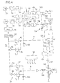
- a device is described below with reference to FIGS. 4 and 5 with which undesired displacements of the beam impact point in the x direction, which were measured in the manner described above, can be compensated for or corrected.
- the output signal from sensor 24 is fed to a pulse shaping circuit 50 (e.g. a Schmitt trigger circuit) which converts the output signal from sensor 24 into a rectangular pulse 52 (FIG. 5C) which has steep leading and trailing edges.
- the leading edge or trailing edge of the rectangular pulse 52 occur when the beam impact spot passes through the viewing area boundary 28a when passing through the measuring triangle and enters or exits the measuring area 28 of the sensor 24.
- a pulse generator circuit 54 which can be triggered by the rising leading edge is connected to the pulse shaping circuit 50 and is e.g. can consist of a monostable multivibrator and, when the leading edge of each pulse 52 occurs, supplies a rectangular pulse 56 (FIG. 5E) which is fed to an input of an AND circuit 58.
- the output of the second sensor 26 is connected to a pulse shaping circuit 60, which supplies rectangular output pulses 62 with steep leading and trailing edges to a pulse generator circuit 64 which, when the leading edge of each rectangular pulse 62 occurs, a short rectangular pulse 66 to an input of a second AND Circuit 68 provides.
- the second inputs of the AND circuits 58 and 68 will a trapezoidal x-deflection signal 70 is supplied by an x-deflection circuit 72, which causes the x-deflection during the measuring periods in which the measuring triangle 22 is passed.
- the y-deflection is effected by a y-deflection circuit 74 during each measurement period an SAE g ezahnsignal generated 76, as shown in Fig. 5B.
- the x deflection circuit 72 may, for example, contain an oscillator 78, the output signal of which is converted by a pulse shaping circuit 80 into a sequence of square-wave pulses having a constant area. These stretching pulses are fed directly to one input of a gate circuit 82 and to one input of a gate circuit 84 via an inverter 86. The outputs of the gate circuits 82 and 84 are connected to one another and to an integrating capacitor 88. Gate 82 is gated by a gate pulse T 1 (FIG. 5G) during the rising edge 70 of the trapezoidal x deflection signal each measurement period so that it then passes the pulses from pulse shaping circuit 80 to integrating capacitor 88 where it produces the rising edge 70a can be integrated. The frequency of the output signal of the oscillator 78 is so high that the rising edge 70a, which in practice is a step function, is sufficiently smooth.
- the gate circuit 84 is switched through during the falling edge 70b of the trapezoidal x deflection signal 70 by a gate pulse T 2 . Since the pulses then passed through the gate circuit 84 due to the inverter 86 have the opposite polarity as the pulses from the gate circuit 82, the charge on the capacitor 88 is reduced again to zero, producing the falling edge 70b.
- the gate pulses T, and T 2 are generated by a clock 90, which can be constructed in a known manner.
- the y deflection circuit 74 is constructed similarly. It contains a gate circuit 92, to which the pulses from the pulse shaping circuit 80 are fed via an inverter 94, and a second gate circuit 96, to which the pulses are fed from the pulse shaping circuit 80 via a non-inverting amplifier circuit 98, which has twice the amplification level as the inverter 94.
- the outputs of the gate circuits 92 and 96 are connected to one another and to an integrating capacitor 100.
- the gate circuit 92 is switched through by the clock generator 90 during the falling edges 76 and 76c of the sawtooth signal 76 by gate pulses T 3 , while the gate circuit 96 is switched through by the clock generator 90 during the rising edge 76b of the sawtooth by a gate pulse T 4 . Since the pulses that are passed through the gate circuit 96 are twice as large as the pulses from the gate circuit 92 because of the difference in the amplification levels of the inverter 94 and the amplifier circuit 98, the rising edge 76b is steeper than the edges 76a and 76c.
- the polarity and amplitude of the control pulses T1 to T 4 shown in FIGS. 5G and 5H are intended to symbolize the polarity and amplitude of the pulses which are passed through by the relevant gate circuits 82, 84, 92 and 96 during the duration of the relevant pulses.
- the x deflection signal which arises at the integrating capacitor 88, is fed to the signal input of the gate circuits 58 and 68.
- the pulses supplied by the pulse generator circuits 54 and 64 to the control inputs of these gate circuits thus cut out a pulse (for example the pulse 102 in FIG. 5F) from the edge 70a of the trapezoidal x deflection signal 70, the amplitude of which corresponds to the amplitude of the trapezoidal x deflection signal 70 corresponds to the moment of occurrence of the leading edge of the pulse 52 or 62.
- Holding circuits 104, 106 are connected to the outputs of the gate circuits 58 and 68, respectively, which hold the sampled signal amplitude until the next sampling during the next measuring period.
- a signal which corresponds to S R is thus available at the output of the holding circuit 104, while a signal which corresponds to S B is available at the output of the holding circuit 106.
- both S R and S B are equal to S 0 .
- differential amplifiers 108 and 112 Two subtraction circuits shown as differential amplifiers 108 and 112 are used to form the differences required to implement equation (4).
- the two inputs of the differential amplifier 108 are connected to the outputs of the holding circuits 104 and 106.
- One input of differential amplifier 112 is connected to the output of holding circuit 106, while at the other input there is a bias voltage corresponding to S o , which is generated by a preferably adjustable bias voltage source 114.
- the output of the differential amplifier 108 is connected to an input of a summing circuit 120 via an amplifier 116, the gain of which is adjustable so that the factor tg ⁇ tg ⁇ can be set.
- the output of the differential amplifier 112 is connected to the other input of the summing circuit.
- a signal is therefore available at the output of summing circuit 120 which is proportional to ⁇ x.
- This signal is preferably fed via an amplitude setting element 122, for example a potentiometer (or a controllable amplifier) to a further summing circuit 124, in which it is combined with the x deflection signal from the integrating capacitor 188.
- the combined x deflection signal is fed via a power amplifier 126 x deflection coils 128 to the electron beam welding machine, which is not shown in any more detail and which can be designed in a known manner.
- SR and SB are both equal to S 0 , so that the output signals of differential amplifiers 108 and 112 are also equal to zero.
- the conditions at the target position of the beam impact point are shown in the left side of FIG. 5.
- the right side of FIG. 5 applies to conditions as have been explained with reference to the lower part of FIG. 3.
- the pulses 56 and 66 no longer occur in the middle of the rising edge 70a of the trapezoidal x-deflection signal (time t 4 ), but at times t ' 4 and t " 4 , as represented by the pulses 56' and 66 ' Accordingly, the output pulses 102 'and 102 "of the gate circuits 58 and 68 also have an amplitude which deviates from the target value (pulse 102; corresponding to SO ), so that a correction signal is produced which compensates for the deviation ⁇ x. Otherwise, the operation of the device should be apparent from the above explanation in connection with FIGS. 4 and 5.
- only one side flank 22a of the measuring triangle was used for measuring purposes and therefore only detected any deviation of the surface of one workpiece part 10a. If desired, however, the other side flank 22b of the measuring triangle can also be used for measuring purposes and the position of the surface of the workpiece part 10b can also be detected. It is only necessary to use additional pulse generator circuits corresponding to the pulse generator circuits 54 and 64, which are responsive to the trailing edge of the pulses 52 and 62, respectively. The gate pulses generated by these pulse generator circuits then control further gate circuits corresponding to the gate circuits 58 and 68, the output signals of which are then processed accordingly to form a further signal ⁇ x ', as was described above for the generation of the signal ⁇ x.
- an average value can be formed and this average value can then be supplied to the adder circuit 124 as a correction signal.
- An additional or alternative use of the signal ⁇ x ' is to form a signal corresponding to the absolute value of the difference (Ax - Ax') and to generate a warning signal if this difference exceeds a predetermined value.
- two differential amplifiers for positive or negative differences
- a connected threshold circuit the outputs of which are connected to an alarm circuit via an OR gate
- a correction signal ⁇ x corresponding to the average height level of the surfaces of the workpiece parts 10a and 10b can also be generated by implementing the following equation:
- An additional pulse generator circuit 54 ' is connected to the output of the pulse shaping circuit 50 and responds to the trailing edges of the output pulses 52 of the pulse shaping circuit 50 .
- the output pulses 56 '(FIG. 5E) of the pulse generator circuit 54' control an additional gate circuit 58 ', the signal input of which is connected to the integrating capacitor 88 and the signal output of which is connected to a holding circuit 104'.
- the output signal of the hold circuit 104 ' is fed together with the output signal of the hold circuit 104 to an averaging circuit 140, in which the output signals of the hold circuits 104 and 104' are summed and adjusted in amplitude so that the Dif Output amplifier 108 supplied output signal of the circuit arrangement 140 corresponds to the right bracket expression in equation (5).
- undesired displacements of the beam impact point in the y direction (or more precisely, displacements of the central beam direction in the y direction at the location of the workpiece surface), which are caused by magnetic interference fields with an x component, can also be detected.
- a further measuring field boundary 150 (FIG. 1) which is parallel to the welding direction (x) and at a distance from the central beam direction 30 (ie at a distance from the joint 12) and in the example according to FIG. 1 is perpendicular to the workpiece surface.
- the measuring field limit 150 can be determined by a separate sensor 152, e.g. an X-ray sensor, but is preferably formed by a sharp lateral measuring field boundary (34d 'in FIGS. 13a and 13c) of a single sensor 27' (FIG. 9), as can be explained with reference to FIGS. 9 to 14.
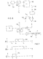
- the circuit arrangement according to FIG. 4 can be supplemented by a circuit arrangement of the type shown in FIG. 6 when the additional sensor is used.
- the additional sensor can be, for example, an X-ray sensor 152 corresponding to sensors 24 and 26.
- a pulse shaping circuit 154 is connected to its output, which corresponds to pulse shaping circuit 50 or 60 and generates an output signal 156 (FIG. 7A) with steep edges.
- the output of the pulse shaping circuit 154 is connected via a gate circuit 158 to a reset input R of a flip-flop 160.
- the pulse-shaped control signal T 4 (FIG. 5H) is fed to the control input of the gate circuit 158, so that the gate circuit 158 is transparent, while the beam is the base side 22c of the measuring triangle 22 (Fig. 1) passes through.
- the control signal T 4 is simultaneously fed to a set input S of the flip-flop 160, which is set by the rising leading edge of the control signal T 4 and, when set, generates an output signal 164 (FIG. 7C) on an output line 162.
- the flip-flop is reset at a variable time t 5 by the leading edge of the shaped output signal 156 of the sensor 152, so that the duration of the output signal 164 of the flip-flop corresponds to the time that the beam has during the measuring period from the beginning of the base side 22c to the limit of the field of view 150 needed. This route is designated y in FIG. 1.
- the output signal 164 of the flip-flop 160 is integrated by an integrating circuit 166 and converted into a DC voltage of corresponding magnitude, which is fed to an input of a subtracting circuit shown as a differential amplifier 168.
- a voltage Vy o is supplied to the other input of the subtracting circuit from an adjustable bias voltage source 170.
- the voltage Vy o corresponds to the setpoint value of y 1 , that is to say the value which the distance between the beginning of the base side 22c and the line of sight limit 150 has if there is no interference magnetic field.
- An error voltage thus occurs at the output of the differential amplifier 168, which represents the magnitudes and signs of the displacements of the beam impingement point in the y direction caused by the interference magnetic field.
- This error voltage is fed via an amplitude adjuster 172 to a summing circuit 174, in which the error voltage is combined with the y deflection voltage 76 (FIG. 5B) or a frond voltage deflecting the beam between the measuring periods in the y direction.
- the frond voltage can be a sinusoidal voltage of, for example, a few 100 or 1000 Hz frequency and is supplied via a line 176.
- the exit of the summing scarf device is coupled to the y deflection coils 130 via a corresponding power amplifier 178.
- the described exemplary embodiments can of course be modified in a wide variety of ways, and the measures explained can in part also be used individually or in other combinations than those described above.
- the height of the measuring triangle calculated in the x direction can be, for example, 6 mm, and the length of the base side 22c can also be 6 mm.
- a measuring period that is to say the time between t 0 and t 3 (FIG. 5A), can be a few milliseconds, for example 2 milliseconds, and the measuring periods can follow one another with a repetition frequency of, for example, 1 Hz to a few hundred Hertz.
- the beam voltage and the beam current are advantageously the same during the measurement period as during welding or machining.
- the speed at which the beam is deflected during the measuring period is expediently so high that there is no undesirable influence on the workpiece.
- An X-ray sensor usually contains a type of counter tube or a scintillation crystal in combination with a photomultiplier. Such sensors deliver an output signal consisting of short pulses, the frequency (number per unit of time) of which depends on the intensity of the X-rays.
- the accuracy of the determination of the point in time at which the beam passes through the sensor measuring range limits depends on a number of parameters, including the beam current strength and the beam focusing (ie the beam diameter on the workpiece surface).
- the rise time of the frequency function for the pulses delivered by the sensor changes, for example in the event of changes in the radiation intensity and thus also the point in time at which a counter value threshold (that is to say a certain number of pulses per unit of time or pulse frequency) is reached by which the exceeding of the measuring range limit is defined.
- the slope of the rise or fall in the frequency function of the sensor output signal decreases, and statistical shifts in time of these rise and fall processes can occur, and thus the point in time at which the count value, which is considered to have exceeded the measuring range limit, is reached , more uncertain. Since the position of this point in time at a reference point in time (for example the beginning of the measuring period) determines the size of the measuring signal, which is then used for position correction, the accuracy of this correction depends on the exactness of the determination of the relevant point in time.
- the preferred embodiment of the invention which is described below with reference to FIGS. 8 to 15, allows a more precise determination of the point in time which is relevant for the derivation of the correction signal, so that a better position correction is possible.
- only a single sensor is required in this embodiment.
- the averaged time therefore allows a much more precise determination of any deviations in the desired distance between the focal spot and because of the spatially fixed, known relationship between the measuring path and the wire feed point (usually both the sensor and the feed mechanism for the additional wire are attached to a common holder with the beam generation system) Wire feed point and thus a correspondingly more precise correction.
- the height of the surface of the workpiece does not change so that the sensor measuring range does not shift on the workpiece surface. But if two sheets to be welded do not match in thickness or if the surfaces are not completely flat, the surface of one sheet is at a different height than that of the other. If the axis of the field of view of the sensor is at an angle to the workpiece surface, then according to the rules of radiation optics, the two parts of the measuring range on the surfaces of the two metal sheets on both sides of the weld joint move relative to each other, so that the area boundaries at the joint no longer merge, but parallel to each other are offset.
- An expedient embodiment of the invention therefore consists in forming a time average from all four different times at which the beam on the measuring path exceeds the measuring range limits, on the basis of which the control signal is then derived and the correction is carried out.
- the position of the measuring range can be determined relatively easily keep constant with respect to the wire immersion point.
- the measuring path is based on the current focal spot, which does not necessarily coincide with the central axis of the jet gun, but must be regulated to compensate for external influences on the desired processing area, the position of the measuring path to the measuring range limits depends on such external influences, and the times when they are exceeded
- the measuring range limits by the beam passing through the measuring path therefore contain information about the positional deviations between the focal spot and the beam gun axis or the machine parts and positions which are related to it in a known spatial relationship, such as the immersion point of the wire supplied as additional material for the weld joint. If the feed direction is again referred to as the x direction, then deviations ⁇ x from the desired distance between the focal spot and the wire immersion point can be determined and corrected in the manner described above.
- the preferred method also allows more precise measurement of deviations of the focal spot from the cannon axis in the y direction running transversely to the feed direction, that is to say lateral emigration ⁇ y of the focal spot with respect to the cannon axis.
- the beam is passed through a measuring path section which crosses the two other measuring range limits running parallel to the weld joint, and the mean value is formed from these two crossing times, which coincides with the y position of the gun axis in the case of symmetrical or undisturbed conditions. This is not the case, then the focal spot has migrated out of this y target position due to interference magnetic fields, ie its y position no longer coincides with that of the cannon or machine axis and must be returned to this target position by an appropriate correction.
- FIG. 8 the welding of two sheets 14 'and 16' with the aid of an electron beam, which is supplied by a beam generation system or a beam gun 30 ', is shown as an illustrative example of a machining process.
- the position of the jet gun is adjusted so that the jet 10 'strikes the weld joint 12' between the sheets 14 'and 16' and generates such a high energy density that a focal spot 18 'is created in which the material melts.
- additional material is carried out e.g. in the form of a wire 20 'from a nozzle 21' behind the focal spot 18 '.
- the focal spot forms the processing point and travels in the feed direction x along the joint 12 '.
- the finished weld is designated 24 '.
- the beam 10 ' can be deflected - conveniently with the help of suitable magnetic fields. Such a case is shown in dash-dot lines in the drawing. Without deflection, the beam 10 "would strike the sheet metal surface next to the joint 12 '. With the help of two magnets 26' and 28 ', magnetic fields of such strength are generated that the beam hits the joint 12' exactly and produces the focal spot 18". Such a focal spot correction may also be necessary if the joint 12 'is straight, if the beam is deflected from its normal course by interference fields or the jet gun 30 'is not exactly positioned.
- the beam 10 ' which in this illustration coincides with the central axis 31' of the beam gun 30 'and runs in the z direction, ends up in the focal spot 18', which is shown here in the sheet metal surface 34 '.
- the beam 10 ' is deflected away from the focal spot 18' along a measuring path, the course of which will be explained in more detail, and then returns to the focal spot 18 'for further processing.
- a measuring area lying in front of the processing point (focal spot 18 ') with pairwise parallel boundary lines or area boundaries is defined on the surface 34', the two of which cross the joint 12 'extending area boundaries 34a' and 34b 'are shown in Fig. 2, while the other two area boundaries are in front of and behind the paper plane.
- the beam 10 'deflected in the x-direction now exceeds the limit 34a' upon entering the measuring range, whereupon the sensor 27 'detects an X-ray radiation resulting from the impingement of the beam 10' on the material surface 34 'and accordingly more pulses per Unit of time provides, i.e. changes the pulse rate from the rest value to a radiation detection value. Ver if the beam 10 'leaves the measuring range beyond the limit 34b', then the sensor 27 'no longer detects any radiation and the pulse rate falls back to the idle value.
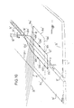
- FIG. 10 shows in perspective the relationships shown in FIG. 9 from the side.
- the three coordinate directions, x for the feed direction of the machining process, y for the transverse direction thereto and z for the perpendicular (direction of the beam gun axis 31 ') are also drawn in here.
- the beam 10 ' is deflected back and forth in the direction of the double arrow W, so that it detects the sheet metal edges on both sides for processing.
- the machining process is interrupted for such a short time that the welding process is not disturbed, and during the measuring period the beam 10 'is guided by a corresponding deflection along a measuring path 22' running through the measuring range, which starts from the focal spot 18 'and returns to it .
- all other parameters of the beam such as beam current and focusing, can advantageously be left constant.
- the output signal of the sensor 27 ' changes since it only perceives the background radiation as long as the beam 10' is outside the measuring range enclosed by the limits 34a 'to 34d'.
- the X-ray radiation which arises from points of the surface 34 ′ lying outside the measuring range when the beam 10 ′ strikes, is not perceived by the sensor. If, on the other hand, the beam impact point enters the measuring range, the X-ray radiation emanating from this point of impact reaches the sensor, which registers it by a sudden increase in its output pulse rate or the frequency function. As long as the beam 10 'strikes the material surface 34' within the measuring range with the limits 34a 'to 34d', the pulse rate of the sensor 27 'is higher than at beam impact points outside the measuring range.
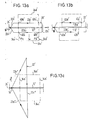
- FIGS. 11 and 12 show the radiation intensity determined in the measuring range, and thus the size of the pulse rate J, over time. 11, when the focus is optimal, a relatively steep jump occurs when the beam, for example, exceeds the limit 34a 'of the measuring range at point 40a' and enters the measuring range. Since the I mpulsrate before and not absolute behind the jump con- s tant runs, the lower and upper mean value in the figure are entered.
- FIG. 11b shows a case with a larger beam diameter (defocusing), which leads to the change in the frequency function taking place more slowly than in FIG. 11a and the time range ⁇ t within which the evaluation circuit responds becomes correspondingly larger, so that the time of exceedance can be determined even less precisely, that is, it becomes less clear.
- a similar effect occurs when the beam current is too small, where the radiation intensity is not so strong and therefore the upper pulse rate is lower, so that the count value at which the evaluation circuit responds is more likely to occur in the flatter upper part of the frequency curve. This also makes the unsharpness range ⁇ t larger than in the case of FIG. 11a.
- Figure 13 illustrates only a few measurement path forms for the derivation of different control signals.
- the rectangular measuring area with the limits 34a 'to 34d' is traversed by a measuring path 22 'elongated in the feed direction x with the sections 22a' to 22e '.
- the measuring path crosses the measuring range limits 34a' and 34b 'at the points 40a' and 40b ', and in the course of this measuring path section the sensor output signal looks approximately as shown in FIG.
- the much more exact temporal mean value T M between the actual switching points in time at points 40a 'and 40b' is thus determined in the method described here defines the exact center of the measurement range along its boundaries 34c 'and 34d'.
- the unsharpness ranges ⁇ t E and ⁇ t A as well as the exact mean time T M are indicated for illustration.
- the situation can be determined the focal spot 18 'with respect to a machine reference point - such as the beam gun axis - in the x direction agree and regulate in a desired manner so that, for example, the distance between the focal spot 18 'and the immersion point of the additional wire 20' in the weld pool in the x-direction can be kept at an optimum value.
- a measuring path as shown in FIG. 13c as a triangle is suitable for determining the position in the y direction, one corner point of which lies in the focal spot 18 'and the opposite side 22c "of which the measuring range limits 34c' and 34d 'and between them the joint 12'
- the return and return sections of the measuring path are designated 22a "and 22e".
- a sensor output signal with a frequency curve of the type illustrated in FIG. 12 is again generated.
- an exact time value is again obtained for the derivation of a control signal for an Ay position control, for example for tracking the wire feed point with respect to the focal spot.
- FIG. 14 An arrangement is schematically illustrated in FIG. 14, with the aid of which the sensor signals can be evaluated to form the desired control signals.
- the sensor 27 On the basis of the X-rays detected in the measuring range, the sensor 27 'emits pulses, the frequency of which corresponds to the radiation intensity. These pulses are fed to a normalization circuit 41 ', in which the pulses are subjected to pulse shaping. It is also determined how many pulses occur per unit of time, and the corresponding count values are then stored in an intermediate memory 42 ', for example in the form of a RAM memory. The count values from the memory locations called are transferred from this buffer into a computer 43 '; a clock circuit 44 'can be used for this purpose, which switches the ON-LINE into the buffer 42' the entered count values can be saved in the computer cycle.
- the computer 43 ' is also connected to the beam deflection circuit 47' and, on the basis of the beam deflection signals determining the measurement path and the count values taken from the buffer 42 ', calculates the relevant points in time, including the mean value T M , and finally also calculates the desired control signals.
- the corresponding output signals of the computer 43 ' are converted with the aid of an information converter 45', which is usually also referred to as an interface, into control signals which, for example, the deflection coils 26 'and 28' (FIG. 8) 46 are fed to the respective actuator 'suitable, which then brings about the desired correction of the position of the beam gun or beam deflection.
- the current in the coils 26 'and 28' can be changed in opposite directions by the control signals so that there is a desired parallel displacement of the beam 10 ".
- the control signals can be supplied to a support controller (not shown) which adjusts the workpiece arrangement in y -Direction. So that the beam is centered with respect to the joint to be welded.
- the beam intensity is reduced during the measuring period.
- the same beam power is preferably used during the measuring period as during the actual machining process, e.g. of welding.
- the beam parameters that are optimal for the machining process are different from the beam parameters that are optimal for the measuring process.
- a typical example of this is the hardening of a workpiece with an electron beam, in which an electron beam of relatively large cross-section is used, which is unfavorable for measuring purposes, as was explained above with reference to FIGS. 11a and 11b. Even when welding, the beam is often not focused as sharply as possible on the workpiece surface.
- a stigmator 144 is now additionally provided, which is preferably arranged between the focusing lens 136 and a workpiece arrangement 146 to be welded.
- the stigmator 144 is connected to a stigmator control unit 148.
- the stigmator 144 and the associated control unit 148 are shown in more detail in FIG. 16.
- the stigmator is a device for generating a multipole field, e.g. a six-pole field.
- the stigmator 144 includes an annular magnetic core 150 with six internally projecting poles and three windings 152a, 152b and 152c.
- Each of the windings is connected to a circuit arrangement in the stigmator control unit 148, for the sake of simplicity only the circuit arrangement 148a for the winding 152a is shown in FIG. 16.
- This circuit arrangement contains two with their emitter-collector paths between a positive (+) and negative (-) terminal of an earth-symmetrical voltage source (not shown) and the one terminal of the winding 152a connected complementary transistors 154 and 156.
- the other terminal of this winding is grounded.
- the base electrodes of the two transistors are coupled to the output of a digital / analog converter 158, the input of which is connected to a corresponding output 159a of a microcomputer 160.
- the circuit arrangement 148a can be controlled by the computer in such a way that a current of the desired amplitude and polarity flows through the winding 152a.
- the windings 152b and 152c can be controlled in a corresponding manner, so that a desired multipole field can be generated in the region of the beam 110, which causes a stigmatic distortion of the beam cross section. This is shown in Fig. 17.
- the round one during welding (Exaggeratedly large) beam cross-section 110a is advantageously deformed during welding by the field of stigmator 144 so that, as shown at 110b, it has a fine tip 110c.
- the measuring range limit e.g. the measuring range limit 34b '(see also 13) so that the sensor only detects the part of the beam impact leak formed by the tip 110c. If the beam is then deflected in the direction of the arrow over the weld joint 12 ', the fine tip results in a very sharp and well-defined sensor output signal.
- FIG. 18 shows, it may also be expedient to "astigmatize" the beam such that it has a tip 110c 'running in the scanning direction (arrow).
- the measuring range limit 34d ' is exceeded, an output signal with a profile as shown in FIG. 19 is obtained.
- This course offers the possibility of using a threshold value circuit to generate a well-defined sensor signal, which occurs in FIG. 19, for example, at time t 0 .
- the computer 160 which is controlled by a clock generator, is programmed in such a way that it initiates a measuring process at specific time intervals or after a predetermined feed distance.
- the measuring program is read from a suitably programmed memory.
- Deflection power supply 142 is supplied with deflection signals from the computer, which result in the desired course of the measurement path (e.g. 22 'in FIG. 13).
- the computer also supplies digital control signals to the stigmator control unit 148, which are converted by the digital / analog converters 158 into control signals for the transistors 154, 156. As a result, the beam cross section is astigmatically distorted in the desired manner. Otherwise, the device works in the manner described above.
- the astigmatic deformation of the beam cross section described and the stigmator 144 which can be controlled as desired in the course of a processing and / or measuring process can also be used advantageously in charge beam processing devices other than those described above.
- a "fast" auxiliary focusing lens 144a is preferably arranged close behind the main focusing lens 136, which e.g. can contain an iron coreless coil with a correspondingly low self-induction, so that the field generated by the auxiliary focusing lens can be switched over quickly.
- the refractive power of the auxiliary focusing lens can e.g. to about 20% of the refractive power of the main focusing lens 136.
- the auxiliary focusing lens can be powered by a control circuit similar to control circuit 148a in FIG. 16.
- auxiliary focusing lens 144a which together with the unchanged field of the main focusing lens 136 ensures a sharp focusing of the electron beam 110 on the surface 146 of the workpiece (Fig. 15) and accordingly gives very accurate measured values.
- the control of the current of the auxiliary focusing lens can be done by the computer 160, as described above in connection with the stigmator.
Abstract
Bei einer Ladungsträgerstrahl -Werkzeugmaschine, wie einer Elektronenstrahl -Schweißmaschine, wird die Position des Fleckes, wo der Ladungsträgerstrahl (14) während der Bearbeitung einer Werkstückanordnung (10) auf deren Oberfläche auftrifft, bezüglich der Achse (30) eines den Strahl liefernden Strahlerzeugungssystems dadurch geregelt, daß der Strahl während kurzer, den Bearbeitungsvorgang unterbrechender Meßperioden längs eines geschlossenen Meßweges (22) abgelenkt wird, der eine zu bearbeitende Zone (12) der Werkstückanordnung (10) in Bearbeitungs- oder Vorschubrichtung (x) vor dem augenblicklichen Bearbeitungsbereich (12) kreuzt, die im Strahlauftreff-Fleck entstehende Röntgenstrahlung durch eine Röntgenstrahlungssensoranordnung erfaßt wird, welche mindestens eine scharfe Meßbereichsgrenze (28a, 150) hat, die im Abstand vom Bearbeitungsbereich (18) verläuft und den Meßweg (22) schneidet, und ein Stellsignal für eine in Vorschubrichtung (x) und/oder eine quer (y) zu dieser wirkende Stellvorrichtung in Abhängigkeit von der mittels der Röntgenstrahlungssensoranordnung bestimmten Größe eines Stückes des Meßweges zwischen einer Meßweg-Referenzposition (18) und der Stelle (40), wo der Meßweg die Meßbereichsgrenze schneidet, erzeugt wird. Zur Erhöhung der Meßgenauigkeit kann der Strahlquerschnitt während der Meßperioden durch eine ladungsträgeroptische Vorrichtung, wie einen Stigmator oder eine Hilfsfokussierungslinse gegenüber dem während des Bearbeitungsvorganges verwendeten Strahlquerschnitt geändert werden.In a charge carrier beam machine tool, such as an electron beam welding machine, the position of the spot where the charge carrier beam (14) strikes its surface during the machining of a workpiece arrangement (10) is thereby regulated with respect to the axis (30) of a beam generating system that supplies the beam that the beam is deflected during a short measuring period interrupting the machining process along a closed measuring path (22) which crosses a zone (12) of the workpiece arrangement (10) to be machined in the machining or feed direction (x) in front of the current machining region (12) , the X-radiation arising in the beam impact spot is detected by an X-ray sensor arrangement which has at least one sharp measuring range limit (28a, 150), which runs at a distance from the processing area (18) and intersects the measuring path (22), and an actuating signal for a in the feed direction (x) and / or an S acting transversely (y) to this tell device is generated depending on the size of a piece of the measuring path determined by means of the X-ray radiation sensor arrangement between a measuring path reference position (18) and the point (40) where the measuring path intersects the measuring range limit. To increase the measuring accuracy, the beam cross section can be changed during the measuring periods by means of a charge carrier optical device, such as a stigmator or an auxiliary focusing lens, compared to the beam cross section used during the machining process.
Description
Die vorliegende Erfindung betrifft ein Verfahren und eine Einrichtung zur Positionsregelung eines Ladungsträgerstrahles, insbesondere Elektronenstrahles, in einer Ladungsträgerstrahl-Werkzeugmaschine.The present invention relates to a method and a device for position control of a charge carrier beam, in particular an electron beam, in a charge carrier beam machine tool.
Ein bevorzugtes Anwendungsgebiet des Verfahrens gemäß der Erfindung ist die Positionsregelung beim Ladungsträgerstrahl-, insbesondere Elektronenstrahlschweißen. Das Verfahren gemäß der Erfindung läßt sich jedoch auch bei anderen Ladungsträgerstrahlbearbeitungsverfahren mit Vorteil verwenden, z.B. beim Elektronenstrahl-Fräsen, -Schneiden, -Gravieren u.a.m. Elektronenstrahl-Schweißmaschinen sind z.B. aus der US-PS 2 793 281 bekannt.A preferred field of application of the method according to the invention is position control in charge carrier beam welding, in particular electron beam welding. However, the method according to the invention can also be used with advantage in other charge beam processing methods, e.g. when electron beam milling, cutting, engraving etc. Electron beam welding machines are e.g. known from US-PS 2,793,281.
Bei der Bearbeitung eines Werkstückes mittels eines Ladungsträgerstrahles ist es oft erforderlich, den Fleck, wo der Strahl auf die Merkstückoberfläche auftrifft, auf einer Maschinenachse (Achse des Strahlerzeugungssystems) zu halten oder allgemeiner die Position des Strahlauftreff-Fleckes bezüglich einer Referenzposition zu regeln, die eine feste Lagebeziehung zum Strahlerzeugungssystem hat. So ist es z.B. beim Elektronenstrahlschweißen mit Zusatzmaterial, das gewöhnlich in Form eines Drahtes, Stabes oder Bandes in den Schweißbereich eingeführt wird, wichtig, einen vorgegebenen, konstanten Abstand zwischen dem Strahlauftreff-Fleck und dem Punkt, bei dem das Zusatzmaterial in den Schweißbereich eintritt, aufrechtzuerhalten, damit die Strömungsverhältnisse innerhalb des Schmelzbades im Schweißbereich durch das Zusatzmaterial nicht ungünstig beeinflußt werden. Ähnliche Verhältnisse liegen vor, wenn der in Bearbeitungs- richtung (Vorschubrichtung, x-Richtung) gemessene Abstand des Strahles zu einer anderen Zusatzvorrichtung konstant gehalten werden soll, z.B. einer mit dem Strahl bewegten Schweißbadunterstützungsvorrichtung, die das Ausfließen der Schmelze aus dem Schweißbereich verhindern soll. Ferner ist eine feste Relation zwischen der Position des Strahlerzeugungssystems und der des Werkstückes erforderlich, wenn der betreffende Elektronenstrahl-Bearbeitungsvorgang bei vorprogrammierter Relativbewegung zwischen Strahlerzeugungssystem und Werkstück mit hoher Präzision durchgeführt werden soll.When machining a workpiece using a charge carrier beam, it is often necessary to keep the spot where the beam hits the surface of the memorandum on a machine axis (axis of the beam generation system) or, more generally, to regulate the position of the beam impact spot with respect to a reference position, the one has a fixed positional relationship to the beam generation system. So it is e.g. When electron beam welding with filler material, which is usually introduced into the welding area in the form of a wire, rod or ribbon, it is important to maintain a predetermined, constant distance between the beam impact spot and the point at which the filler material enters the welding area so that the Flow conditions within the weld pool in the welding area are not adversely affected by the additional material. Similar conditions exist if the distance of the beam from another additional device measured in the machining direction (feed direction, x-direction) is to be kept constant, e.g. a weld pool support device which is moved with the jet and is intended to prevent the melt from flowing out of the welding area. Furthermore, a fixed relationship between the position of the beam generation system and that of the workpiece is required if the electron beam processing operation in question is to be carried out with high precision with a preprogrammed relative movement between the beam generation system and the workpiece.
Das draht- oder bandförmige Zusatzmaterial (im folgenden kurz "Zusatzdraht") wird gewöhnlich schräg, d.h. mit einem von null verschiedenen Winkel bezüglich der mittleren Achse des Elektronenstrahls in den Schweißbereich eingeführt. Der in Schweißrichtung (x-Richtung) gerechnete Abstand zwischen der Auftreffstelle des Elektronenstrahls und der Position des Zusatzdrahtes in der Ebene der Werkstückoberfläche kann sich durch Magnetfelder mit einer senkrecht zur Strahlrichtung (z-Richtung) und zur Schweißrichtung gerichteten Komponente (Komponente in y-Richtung) und/oder durch Änderungen des Arbeitsabstandes in Strahlrichtung (z-Richtung), d.h. Änderungen des Abstandes zwischen dem Strahlerzeugungssystem und der Werkstückoberfläche, ändern.The wire or ribbon-shaped additional material (hereinafter referred to as "additional wire" for short) is usually introduced into the welding area at an angle, ie with a non-zero angle with respect to the central axis of the electron beam. The distance calculated in the welding direction (x-direction) between the point of impact of the electron beam and the position of the additional wire in the plane of the workpiece surface can be changed by magnetic fields with a perpendicular to the beam direction (z-direction) and to Component directed in the welding direction (component in the y direction) and / or by changing the working distance in the beam direction (z direction), ie changes in the distance between the beam generation system and the workpiece surface.
Es ist aus der DE-OS 28 21 028 bekannt, die Position des Elektronenstrahls in x- oder Schweißrichtung in der Nähe der Werkstückoberfläche bezüglich des Strahlerzeugungssystems durch eine nadelförmige Sondenelektrode zu messen, die parallel zur Werkstückoberfläche und in nahem Abstand von dieser rotiert und dabei periodisch durch den Strahl läuft. Die Lage des in der Nähe des Schweißbereiches befindlichen Teiles der Werkstückoberfläche in z-Richtung wurde durch beidseits der Schweißnaht angeordnete mechanische Tastsensoren gemessen. Eine Messung mit bewegten mechanischen Tastsensoren bzw. Sondenelektroden ist jedoch nicht unproblematisch, da in der Nähe des Schweißbereiches einer mit höherer Leistung arbeitenden Elektronenstrahl-Schweißmaschine hohe Temperaturen herrschen und Verunreinigungen durch verspritzendes Material auftreten können. Dies kann sowohl die Meßgenauigkeit als auch die Betriebssicherheit ungünstig beeinflussen.It is known from DE-OS 28 21 028 to measure the position of the electron beam in the x or welding direction in the vicinity of the workpiece surface with respect to the beam generation system by means of a needle-shaped probe electrode which rotates parallel to and at a close distance from the workpiece surface and periodically runs through the beam. The position of the part of the workpiece surface in the vicinity of the welding area in the z-direction was measured by mechanical touch sensors arranged on both sides of the welding seam. A measurement with moving mechanical touch sensors or probe electrodes is not without problems, however, since high temperatures prevail near the welding area of an electron beam welding machine operating at higher power, and contaminants from spraying material can occur. This can adversely affect both the measuring accuracy and the operational reliability.
Aus der oben erwähnten Offenlegungsschrift, insbesondere den Figuren 11 bis 13, ist es ferner bekannt, einen in Schweißrichtung vor dem augenblicklichen Schweißbereich liegenden Teil der Werkstückoberfläche mit dem Elektronenstrahl abzutasten, um die Position einer zu verschweißenden Fuge und/oder deren Breite zu messen. Der Elektronenstrahl wird dabei längs eines Weges abgelenkt, der im wesentlichen die Form eines gleichseitigen Dreiecks hat, dessen durch die beiden gleichen Seiten gebildete Ecke im Schweißbereich liegt und dessen dieser Ecke gegenüberliegende Basisseite im wesentlichen senkrecht zur Schweißrichtung verläuft.From the aforementioned publication, in particular FIGS. 11 to 13, it is also known to scan a part of the workpiece surface lying in the welding direction in front of the current welding area with the electron beam in order to measure the position of a joint to be welded and / or its width. The electron beam is deflected along a path which essentially has the shape of an equilateral triangle, the corner formed by the two identical sides lying in the welding area and the base side opposite this corner extending essentially perpendicular to the welding direction.
Aus der DE-AS 16 15 507 ist ein Verfahren zum Überwachen des Auftreffpunktes eines zum Elektronenstrahlschweißen verwendeten Elektronenstrahles auf einem Werkstück bekannt, bei dem ein in Schweißrichtung vor der augenblicklichen Schweißstelle liegender Teil der Werkstückoberfläche durch den Elektronenstrahl quer zur Schweißrichtung abgetastet wird.From DE-AS 16 15 507 a method for monitoring the point of impact of an electron beam used for electron beam welding on a workpiece is known, in which a part of the workpiece surface lying in the welding direction before the current welding point is scanned by the electron beam transversely to the welding direction.
Der vorliegenden Erfindung liegt die Aufgabe zugrunde, ein Verfahren der letztgenannten Art so weiterzuentwikkeln, daß es zum Kompensieren von Positionsfehlern des Elektronenstrahles in Vorschub- oder Schweißrichtung und quer zu dieser, jeweils bezogen auf eine feste Maschinenachse (insbesondere die Achse des Strahlerzeugungssystems), verwendet werden kann, die durch Störmagnetfelder und/oder Arbeitsabstandsänderungen verursacht werden.The present invention has for its object to further develop a method of the latter type so that it can be used to compensate for position errors of the electron beam in the feed or welding direction and transversely thereto, in each case with respect to a fixed machine axis (in particular the axis of the beam generation system) can be caused by interference magnetic fields and / or changes in working distance.
Diese Aufgabe wird erfindungsgemäß durch das im Patentanspruch 1 gekennzeichnete Verfahren gelöst.This object is achieved by the method characterized in
Vorteilhafte Weiterbildungen und Einrichtungen zur Durchführung des erfindungsgemäßen Verfahrens sind Gegenstand der Unteransprüche.Advantageous further developments and devices for carrying out the method according to the invention are the subject of the dependent claims.
Bei dem Verfahren gemäß der Erfindung wird also die Lage mindestens eines Teiles eines vom Strahlauftreff-Fleck auf der Werkstückoberfläche durchlaufenen Meßweges bezüglich mindestens einer Meßbereichsgrenze bestimmt und dabei mindestens ein Signal erzeugt, das zur Regelung der Strahlposition verwendet werden kann.In the method according to the invention, the position of at least a part of a measuring path traversed by the beam impact spot on the workpiece surface is thus determined with respect to at least one measuring range limit, and at least one signal is generated which can be used to regulate the beam position.
Durch das Verfahren gemäß der Erfindung lassen sich unerwünschte Abweichungen der Position des Elektronenstrahls in Bearbeitungs-Richtung sowie senkrecht zu dieser und zur Strahlrichtung erfassen sowie kompensieren und insbesondere läßt sich auch beim Schweißen mit Zusatzmaterial (Zusatzdraht) der in Schweißrichtung gerechnete Abstand zwischen dem Zusatzdraht und dem Strahl in der Ebene der Werkstückoberfläche auf einem vorgegebenen Wert konstanthalten, sodaß auch bei unebener Werkstückoberfläche und dem Vorhandensein von Störmagnetfeldern unterschiedlicher Intensität einwandfreie Schweißnähte erzielt werden können.The method according to the invention can be used to detect and compensate for undesirable deviations in the position of the electron beam in the machining direction and perpendicular to it and to the beam direction, and in particular also when welding with additional material (additional wire) which is in the welding direction keep the calculated distance between the additional wire and the beam constant in the plane of the workpiece surface at a predetermined value, so that perfect welds can be achieved even with uneven workpiece surfaces and the presence of magnetic fields of different intensities.
Durch eine spezielle Weiterbildung der Erfindung wird zusätzlich die Möglichkeit geschaffen, auch einen Versatz (Höhenunterschied) zweier Werkstückkanten, die eine zu verschweißende Fuge bilden, in z-Richtung meßtechnisch zu erfassen und gegebenenfalls Kompensationsmaßnahmen zu treffen.A special development of the invention additionally creates the possibility of measuring an offset (height difference) of two workpiece edges, which form a joint to be welded, in the z-direction and, if necessary, of taking compensation measures.
Im folgenden werden Ausführungsbeispiele der Erfindung unter Bezugnahme auf die Zeichnung näher erläutert.Exemplary embodiments of the invention are explained in more detail below with reference to the drawing.
Es zeigen:
- Fig. 1 eine schematische perspektivische Ansicht der Oberfläche einer Werkstückanordnung, eines Strahl-Meßweges und der Sichtbereiche zweier Meßstrahlungssensoren, die bei einer Ausführungsform der Erfindung verwendet werden;
- Fig. 2 eine schematische Schnittansicht, die die in Fig. 1 dargestellten Verhältnisse in einer durch die mittlere Strahlachse und die Schweißrichtung definierten x-z-Ebene zeigt;
- Fig. 3 eine schematische Darstellung der Verhältnisse in der x-z-Ebene bei Änderungen des Arbeitsabstandes und der Gegenwart von Störmagnetfeldern mit einer Komponente in y-Richtung (die senkrecht zur Zeichenebene verläuft);
- Fig. 4 ein Blockschaltbild einer Ausführungsform einer erfindungsgemäßen Einrichtung;
- Fig. 5 Diagramme des zeitlichen Verlaufes von Signalen, auf die bei der Erläuterung der Arbeitsweise der Einrichtung gemäß Fig. 4 Bezug genommen wird;
- Fig. 6 ein Blockschaltbild einer Weiterbildung der Einrichtung gemäß Fig. 4;
- Fig. 7 eine graphische Darstellung des zeitlichen Verlaufes von Signalen, auf die bei der Erläuterung der Arbeitsweise der Einrichtung gemäß Fig. 6 Bezug genommen wird;
- Fig. 8 eine schematische Darstellung des Zusammenschweißens zweier Bleche mit Hilfe eines Elektronenstrahls;
- Fig. 9 eine schematische Darstellung eines bevorzugten Meßprinzips, bei dem der Elektronenstrahl während einer Meßperiode die Grenzen des Meßbereiches eines einzigen Röntgenstrahlungssensors überschreitet;
- Fig. 10 eine weitere Darstellung zur Erläuterung dieses Meßprinzips;
- Fig. 11a und b Skizzen zur Erläuterung der Bestimmung des Zeitpunktes der Uberschreitung der Meßbereichtsgrenzen unter verschiedenen auf den Bearbeitungsstrahl einwirkenden Einflußgrößen;
- Fig. 12 eine Darstellung der Häufigkeitsfunktion oder Impulsrate des Sensorausgangssignals zur Veranschaulichung der Verhältnisse beim Eintreten und Verlassen des Meßbereichs durch den Strahl während der Meßperiode;
- Fig. 13a-c Prinzipskizzen zur Erläuterung der Ermittlung verschiedener Meßparameter;
- Fig. 14 eine schematische Darstellung einer bevorzugten, digital arbeitenden Anordnung gemäß der Erfindung zur Ableitung von Fehlersignalen;
- Fig. 15 eine schematische Darstellung eines Ladungsträgerstrahlgerätes gemäß einer weiteren Ausführungsform der Erfindung;
- Fig. 16 ein Schaltbild eines Teiles der Einrichtung gemäß Fig. 15;
- Fig. 17 eine Darstellung der Werkstückoberfläche im Strahlauftreffbereich der Einrichtung gemäß Fig. 15;
- Fig. 18 eine Fig. 17 entsprechende Darstellung für eine etwas andere Situation als sie in Fig.17 dargestellt ist, und
- Fig. 19 eine graphische Darstellung eines Signalverlaufes, wie er bei der Situation gemäß Fig. 18 auftritt.
- 1 shows a schematic perspective view of the surface of a workpiece arrangement, a beam measuring path and the viewing areas of two measuring radiation sensors which are used in one embodiment of the invention;
- Fig. 2 is a schematic sectional view showing the relationships shown in Fig. 1 in an xz plane defined by the central beam axis and the welding direction;
- 3 shows a schematic representation of the relationships in the xz plane when the working distance changes and the presence of interference magnetic fields with a component in the y direction (which runs perpendicular to the plane of the drawing);
- 4 shows a block diagram of an embodiment of a device according to the invention;
- 5 shows diagrams of the time course of signals, to which reference is made in the explanation of the mode of operation of the device according to FIG. 4;
- 6 shows a block diagram of a development of the device according to FIG. 4;
- FIG. 7 shows a graphical representation of the time course of signals, to which reference is made in explaining the mode of operation of the device according to FIG. 6; FIG.
- 8 shows a schematic illustration of the welding of two metal sheets using an electron beam;
- 9 shows a schematic representation of a preferred measuring principle in which the electron beam exceeds the limits of the measuring range of a single X-ray radiation sensor during a measuring period;
- 10 shows a further illustration to explain this measuring principle;
- 11a and b show sketches to explain the determination of the point in time at which the measuring range limits are exceeded under various influencing variables acting on the processing beam;
- 12 shows the frequency function or pulse rate of the sensor output signal to illustrate the conditions when the measuring area enters and leaves the measuring range during the measuring period;
- F ig. 13a-c sketches to explain the determination of various measurement parameters;
- 14 shows a schematic illustration of a preferred, digitally operating arrangement according to the invention for deriving error signals;
- 15 shows a schematic illustration of a charge carrier beam device according to a further embodiment of the invention;
- 16 is a circuit diagram of part of the device according to FIG. 15;
- 17 shows a representation of the workpiece surface in the beam impact area of the device according to FIG. 15;
- FIG. 18 shows a representation corresponding to FIG. 17 for a somewhat different situation than that shown in FIG. 17, and
- FIG. 19 shows a graphical representation of a signal curve as it occurs in the situation according to FIG. 18.
Fig. 1 zeigt eine Werkstückanordnung 10 mit zwei Werkstückteilen 10a und 10b, die zwei einander gegenüberliegende Ränder haben, welche eine zu verschweißende Fuge 12 bilden. Die Fuge 12 wird mittels eines Elektronenstrahls 14 verschweißt, der durch ein nicht dargestelltes Strahlerzeugungssystem einer üblichen Elektronenstrahlschweißmaschine erzeugt wird. Der Elektronenstrahl 14 wird während des Schweißens quer zur Fuge 12 in y-Richtung periodisch abgelenkt ("gewedelt"), was in Fig. 1 durch einen Doppelpfeil 16 angedeutet ist. Ferner wird der Elektronenstrahl durch eine mittels eines Supports oder dergleichen bewirkte Relativbewegung zwischen Strahlerzeugungssystem und Werkstückanordnung 10 längs der Fuge 12 bewegt. Die mittlere Strahlachse (also die Achse des Strahles ohne Ablenkung oder Wedelung) ist dabei im allgemeinen auf die Mitte der Fuge 12 gerichtet und bewegt sich in Schweiß- oder x-Richtung entlang der Fuge. Dort wo der (in y-Richtung) gewedelte Strahl auf die Werkstückanordnung trifft, erzeugt er ein Schmelzbad 18, das mit dem Strahl längs der Fuge wandert und beim Erstarren eine Schweißnaht 20 hinterläßt. Die mittlere Strahlachse fällt gewöhnlich mit der Achse des Strahlerzeugungssystems zusammen.1 shows a
Um eine Messung durchzuführen, wird die die Wedelung 16 bewirkende Strahlablenkung kurzzeitig, z.B. für einige Millisekunden, unterbrochen und der Strahl wird in bekannter Weise längs eines dreieckförmigen Weges 22,' der im folgenden als "Meßtriangel" bezeichnet werden soll, abgelenkt. Der Meßtriangel hat im wesentlichen die Form eines gleichseitigen Dreiecks mit zwei schräg zur x-Richtung verlaufenden, wenigstens annähernd gleichen Seiten 22a und 22b, die sich in einer Ecke etwa in der Mitte des Schweißbades 18 treffen, sowie eine Basisseite 22c, die quer zur Schweißrichtung x und Fuge 12, also im wesentlichen in y-Richtung, verläuft. Bei dem aus der DE-OS 28 21 028 bekannten Verfahren wird lediglich die Basisseite 22c zu Meßzwecken ausgenutzt, um die Breite der Fuge 12 und/oder die Strahlposition in y-Richtung relativ zum Spalt zu bestimmen. Die Geschwindigkeit, mit der der Strahl die Seiten des Meßtriangels durchläuft, ist zweckmäßigerweise konstant.To carry out a measurement, the
Bei dem Verfahren gemäß der Erfindung wird nun mindestens eine der anderen Seiten 22a, 22b, die im folgenden als "Seitenflanken" des Meßtriangels bezeichnet werden sollen, in Verbindung mit zwei Sensoren, vorzugsweise Röntgenstrahlungssensoren, die unterschiedliche Meßfeldbegrenzungen haben, zu Meßzwecken und zur Erzeu- gung von Signalen verwendet, mit denen weitere Information über die geometrischen Verhältnisse in der Umgebung des Schweißbereiches gewonnen und/oder die Strahlposition geregelt werden kann.In the method according to the invention, at least one of the
Bei dem im folgenden beschriebenen Ausführungsbeispiel werden zwei Röntgenstrahlungssensoren 24 und 26 verwendet, welche auf die Röntgenstrahlung ansprechen, die der auf die metallischen Werkstückteile 10a und 10b auftreffende Elektronenstrahl erzeugt. Die Leistung des Elektronenstrahls kann während der Meßperiode, in der er den Meßtriangel 22 durchläuft, z.B. durch eine entsprechende Erhöhung der negativen Spannung an einer Wehnelt-Elektrode des Strahlerzeugungssystems von der Schweiß- le#stung auf eine geringere Leistung herabgesetzt werden, die beispielsweise in der Größenordnung von 10 Watt liegen kann.In the exemplary embodiment described below, two
Wie Fig. 2 zeigt, hat der erste Sensor 24 ein Gesichtsfeld 28, das in der xz-Ebene in der dargestellten Weise schräg zur mittleren Strahlrichtung 30 des Elektronenstrahles 14 verläuft und eine parallel zur y-Richtung (die in Fig. 2 senkrecht zur Zeichenebene verläuft) verlaufende obere Grenze 28a hat. Als Sensor 24 kann z.B. der Röntgenstrahlungssensor verwendet werden, der bei dem bekannten Verfahren gemäß der DE-OS 28 21 028 zur y-Strahlpositions- und Fugenbreitenmessung dient (Sensor 32 in Fig. 4 und 8 der Offenlegungsschrift). Der zusätzliche zweite Sensor 26 ist so angeordnet, daß sein Gesichtsfeld 32 eine dem Strahl 14 zugewandte "hintere" Grenze 32a hat, die parallel zur mittleren Strahlrichtung 30 (z-Richtung) und y-Richtung verläuft und die "hintere" Gesichtsfeldgrenze 28a des Gesichtsfeldes 28 des ersten Sensors 24 in einer Schnittgeraden 35 schneidet, die in einer Ebene 34 verläuft, die durch den dem Soll-Arbeitsabstand entsprechenden Punkt z = 0 geht und senkrecht zur z-Richtung verläuft. Der erste Sensor 24 kann also beispielsweise in der xz-Ebene angeordnet sein und der zweite Sensor 26 in einer Ebene, die in Schweißrichtung gesehen in einem gewissen Abstand, der kleiner als die x-Abmessung des Meßtriangels 22 ist, vor der die mittlere Strahlachse 30 enthaltenden yz-Ebene liegt.As shown in FIG. 2, the
Der Meßtriangel 22, der vom Strahl 14 in z.B. zwei Millisekunden und mit einer Wiederholungsfrequenz von z.B. wenigen Hertz bis einigen hundert Hertz durchlaufen wird, kann in bekannter Weise erzeugt und bemessen werden. Die zur y-Richtung im wesentlichen parallele Basisseite 22c kann wie bisher zur y-Positionsmessung des Strahles bezüglich der Fuge und/oder zur Fugenbreitenmessung verwendet werden.The measuring
In Fig. 3 sind die geometrischen Verhältnisse in der Nähe der Schweißstelle im Maßstab 10:1 vergrößert in einem Schnitt in der xz-Ebene dargestellt. Auf diese Figur wird bei der folgenden Erläuterung des vorliegenden Verfahrens hauptsächlich Bezug genommen.In Fig. 3, the geometric conditions in the vicinity of the welding point on a scale of 10: 1 are shown enlarged in a section in the xz plane. This figure is mainly referred to in the following explanation of the present method.
Mit 34 ist wieder die Ebene dargestellt, die die Schnittlinie 35 der hinteren Gesichtsfeldgrenzen 28a und 32a enthält. Die Ebene 34 stellt gleichzeitig die Soll-Ebene (z = 0) für die Werkstückoberfläche dar. Beim Einrichten der Werkstückanordnung in Vorbereitung des Schweißvorganges wird die Werkstückoberfläche am Anfang der Schweißnaht bzw. Fuge 12 im wesentlichen in diese Ebene gebracht. Wenn keine Störmagnetfelder vorhanden sind, schneidet die mittlere Strahlrichtung 30 die Ebene 34 in einem Soll-Auftreffpunkt 36. Beim Schweißen bewegt sich die mittlere Strahlrichtung 30 in x-Richtung. Ein Zusatzdraht 38 wird in der xz-Ebene unter einem Winkel φ so zugeführt, daß er in einem Soll-Abstand x hinter der mittleren Strahlrichtung 30 des unabgelenkten Strahles die Ebene 34 durchsetzt und in das Schweißbad (in Fig. 3 nicht dargestellt) eintritt.34 again shows the plane which contains the
Während jeder Meßperiode durchläuft der Strahl den Meß- triangel 22, wobei der Strahlauftreffpunkt während des Durchlaufens der Seitenflanken 22a und 22b (Fig. 1) sich sowohl in y-Richtung als auch in x-Richtung bewegt. Infolge der Bewegung in x-Richtung erreicht der Strahlauftreffpunkt schließlich eine Stelle 40 (Fig. 1) auf der Schnittgeraden 35 und tritt dadurch gleichzeitig in das Gesichtsfeld der beiden Sensoren 24 und 26 (Fig. 2) ein, deren Ausgangssignal dann entsprechend ansteigt.During each measurement period, the beam passes through the M
Es sei nun angenommen, daß sich der Arbeitsabstand durch eine Unebenheit der Werkstückoberfläche um Δz vergrößert und gleichzeitig ein Störmagnetfeld auftritt, welches den Strahl um eine Strecke ΔSB in negativer x-Richtung, also in Richtung auf den Zusatzdraht 38 hin, ablenkt. Die Ebene, in der sich die Werkstückoberfläche nun befindet, ist in Fig. 3 mit 34a bezeichnet und die mittlere Richtung des Elektronenstrahls (also die Richtung des durch das Störmagnetfeld abgelenkten Elektronenstrahls ohne Wedelung) schneidet die Ebene 34a im Punkt 36a. Der Punkt 36a stellt also die Ist-Strahlauftreffstelle dar. Der Abstand zwischen der Stelle, wo der Zusatzdraht 38 die Ebene 34a erreicht, und der Ist-Strahlauftreffstelle 36a ist daher nur noch gleich xI. Die zur Herstellung des Soll-Abstandes xD zwischen der Stelle 42a, wo der Zusatzdraht 38 die Ebene 34a erreicht, und der Ist-Strahlauftreffstelle 36a ist also eine korrigierende Strahlablenkung des Betrages Δx in x-Richtung erforderlich. Die Strahlkorrektur Δx setzt sich zusammen aus der durch das Störmagnetfeld verursachten Strahlablenkung ΔSB, die rückgängig zu machen ist, und aus der durch die Änderung des Arbeitsabstandes verursachten Korrektur ΔSZ Δz · tg φ, in die der Zuführungswinkel φ des Zusatzdrahtes eingeht.It is now assumed that the working distance increases due to an unevenness of the workpiece surface by Δz and at the same time an interference magnetic field occurs which deflects the beam by a distance Δ SB in the negative x direction, that is to say in the direction of the
Um den Soll-Abstand xD zwischen der Strahlauftreffstelle und der Stelle, an der der Zusatzdraht die Ebene der Werkstückoberfläche erreicht, wiederherzustellen, ist also die folgende Verschiebung Δx der Strahlauftreffstelle erforderlich:
Aus Fig. 3 ergibt sich ferner die folgende Beziehung:
- SB der in x-Richtung gemessene Abstand zwischen der Sichtbereichsgrenze 32a und dem Ist-Strahlauftreff-
Fleck 36a, - SR der in x-Richtung gerechnete Abstand zwischen der Ist-
Strahlauftreffstelle 36a und einerSchnittgeraden 28b zwischen derEbene 34a und derSichtbereichsgrenze 28a desSensors 1 und - a der Winkel zwischen der
Ebene 34 bzw. 34a und der (ebenen)Sichtbereichsgrenze 28a ist.
- S B is the distance, measured in the x-direction, between the
visual range limit 32a and the actualbeam impact spot 36a, - S R is the distance calculated in the x direction between the actual
beam impact point 36a and a line ofintersection 28b between theplane 34a and thevisual range limit 28a of thesensor 1 and - a is the angle between the
plane visual range boundary 28a.
Aus Fig. 3 ist ferner die folgende Beziehung zu entnehmen:
Durch Einsetzen der Gleichungen (2) und (3) in die Gleichung (1) erhält man:
Die Gleichung (4) enthält den Maschinenkonstanten S tg a und tg φ die Meßgrößen SB und SR. Die Größe SB läßt sich direkt mit dem Sensor 2, die Meßgröße SR mit dem Sensor 1 messen, sie entsprechen jeweils der x-Komponente der Strahlablenkung während einer Seitenflanke des Meßtriangels, also dem in x-Richtung gemessenen Abstand zwischen dem Anfang (Punkt 36a) des dreieckförmigen Ablenkungsweges und dem Punkt, wo der Strahlauftreffpunkt die Gesichtsfeldgrenzen 32a bzw. 28a des zweiten Sensors 32 bzw. die des ersten Sensors 24 überschreitet.Equation (4) contains the machine constants S tg a and tg φ the measured variables S B and S R. The quantity S B can be measured directly with the sensor 2, the measurement quantity S R with the
Im folgenden wird unter Bezugnahme auf die Figuren 4 und 5 eine Einrichtung beschrieben, mit der unerwünschte Verlagerungen des Strahlauftreffpunktes in x-Richung, die in der oben beschriebenen Weise gemessen wurden, kompensiert oder ausgeregelt werden können.A device is described below with reference to FIGS. 4 and 5 with which undesired displacements of the beam impact point in the x direction, which were measured in the manner described above, can be compensated for or corrected.
Das Ausgangssignal des Sensors 24 wird einer Impulsformungsschaltung 50 (z.B. einer Schmitt-Trigger-Schaltung) zugeführt, die das Ausgangssignal des Sensors 24 in einen Rechteckimpuls 52 (Fig. 5C) umformt, der steile Vorder-und Rückflanken hat. Die Vorderflanke bzw. Rückflanke des Rechteckimpulses 52 treten auf, wenn der Strahlauftreff-Fleck beim Durchlaufen des Meßtriangels die Sichtbereichsgrenze 28a durchläuft und in den Meßbereich 28 des Sensors 24 eintritt bzw. aus diesem austritt. An die Impulsformungsschaltung 50 ist eine durch die ansteigende Vorderflanke auslösbare Impulsgeneratorschaltung 54 angeschlossen, die z.B. aus einem monostabilen Multivibrator bestehen kann und beim Auftreten der Vorderflanke jedes Impulses 52 einen Rechteckimpuls 56 (Fig. 5E) liefert, der einem Eingang einer UND-Schaltung 58 zugeführt wird.The output signal from
In entsprechender Weise ist der Ausgang des zweiten Sensors 26 mit einer Impulsformungsschaltung 60 verbunden, die rechteckförmige Ausgangsimpulse 62 mit steiler Vorder- und Rückflanke an eine Impulsgeneratorschaltung 64 liefert, die beim Auftreten der Vorderflanke jedes Rechteckimpulses 62 einen kurzen Rechteckimpuls 66 an einen Eingang einer zweiten UND-Schaltung 68 liefert.Correspondingly, the output of the
Den zweiten Eingängen der UND-Schaltungen 58 und 68 wird ein trapezförmiges x-Ablenksignal 70 von einer x-Ablenkschaltung 72 zugeführt, die die x-Ablenkung während der Meßperioden, in der der Meßtriangel 22 durchlaufen wird, bewirkt. Die y-Ablenkung wird durch eine y-Ablenkschaltung 74 bewirkt, die während jeder Meßperiode ein Sägezahnsignal 76 erzeugt, wie es in Fig. 5B dargestellt ist.The second inputs of the AND
Die x-Ablenkschaltung 72 kann beispielsweise einen Oszillator 78 enthalten, dessen Ausgangssignal durch eine Impulsformungsschaltung 80 in eine Folge von Rechteckimpulsen konstanten Flächeninhalts umgewandelt wird. Diese Reckteckimpulse werden dem einen Eingang einer Torschaltung 82 direkt und einem Eingang einer Torschaltung 84 über einen Inverter 86 zugeführt. Die Ausgänge der Torschaltungen 82 und 84 sind miteinander und mit einem Integrierkondensator 88 verbunden. Die Torschaltung 82 wird während der ansteigenden Flanke 70 des trapezförmigen x-Ablenksignals jeder Meßperiode durch einen Torimpuls T1 (Fig. 5G) durchgeschaltet, so daß sie dann die Impulse von der Impulsformungsschaltung 80 zum Integrierkondensator 88 durchläßt, wo sie unter Erzeugung der ansteigenden Flanke 70a integriert werden. Die Frequenz des Ausgangssignales des Oszillators 78 ist so hoch, daß die ansteigende Flanke 70a, die ja in der Praxis eine Treppenfunktion ist, genügend glatt ist.The
Die Torschaltung 84 wird während der abfallenden Flanke 70b des trapezförmigen x-Ablenksignals 70 durch einen Torimpuls T2 durchgeschaltet. Da die von der Torschaltung 84 dann durchgelassenen Impulse wegen des Inverters 86 die entgegengesetzte Polarität haben wie die Impulse von der Torschaltung 82, wird die Ladung am Kondensator 88 unter Erzeugung der abfallenden Flanke 70b wieder bis auf null verringert. Die Torimpulse T, und T2 werden durch einen Taktgeber 90 erzeugt, der in bekannter Weise aufgebaut sein kann.The
Die y-Ablenkschaltung 74 ist ähnlich aufgebaut. Sie enthält eine Torschaltung 92, der die Impulse von der Impulsformerschaltung 80 über einen Inverter 94 zugeführt werden und eine zweite Torschaltung 96, der die Impulse von der Impulsformungsschaltung 80 über eine nichtinvertierende Verstärkerschaltung 98 zugeführt werden, die den doppelten Verstärkungsgrad hat wie der Inverter 94. Die Ausgänge der Torschaltungen 92 und 96 sind miteinander und einem Integrierkondensator 100 verbunden. Die Torschaltung 92 wird während der abfallenden Flanken 76 und 76c des Sägezahnsignals 76 durch Torimpulse T3 vom Taktgeber 90 durchgeschaltet, während die Torschaltung 96 während der ansteigenden Flanke 76b des Sägezahns durch einen Torimpuls T4 vom Taktgeber 90 durchgeschaltet wird. Da die Impulse, die von der Torschaltung 96 durchgelassen werden, wegen des Unterschiedes der Verstärkungsgrade des Inverters 94 und der Verstärkerschaltung 98 die doppelte Amplitude haben wie die Impulse von der Torschaltung 92, ist die ansteigende Flanke 76b steiler als die Flanken 76a und 76c.The
Die in Fig. 5G und 5H dargestellte Polarität und Amplitude der Steuerimpulse T1bis T4 soll die Polarität bzw. Amplitude der Impulse versinnbildlichen, die von den betreffenden Torschaltungen 82, 84, 92 bzw. 96 während der Dauer der betreffenden Impulse durchgelassen werden.The polarity and amplitude of the control pulses T1 to T 4 shown in FIGS. 5G and 5H are intended to symbolize the polarity and amplitude of the pulses which are passed through by the
Das x-Ablenksignal, das am Integrierkondensator 88 entsteht, wird dem Signaleingang der Torschaltungen 58 und 68 zugeführt. Die den Steuereingängen dieser Torschaltungen zugeführten Impulse von den Impulsgeneratorschaltungen 54 und 64 schneiden also aus der Flanke 70a des trapezförmigen x-Ablenksignals 70 jeweils einen Impuls (z.B. den Impuls 102 in Fig. 5F) aus, dessen Amplitude der Amplitude des trapezförmigen x-Ablenksignals 70 im Augenblick des Auftretens der Vorderflanke des Impulses 52 bzw. 62 entspricht.The x deflection signal, which arises at the integrating
An die Ausgänge der Torschaltungen 58 bzw. 68 sind Halteschaltungen 104, 106 angeschlossen, die die abgetastete Signalamplitude bis zur nächsten Abtastung während der nächsten Meßperiode halten. Am Ausgang der Halteschaltung 104 steht also ein Signal zur Verfügung, das SR entspricht, während am Ausgang der Halteschaltung 106 ein Signal zur Verfügung steht, das SB entspricht. Bei Soll-Lage des Strahlauftreffpunktes sind sowohl SR als auch SB gleich S0.Holding
Zur Bildung der zur Realisierung der Gleichung (4) benötigten Differenzen dienen zwei als Differenzverstärker 108 und 112 dargestellte Subtrahierschaltungen. Die beiden Eingänge des Differenzverstärkers 108 sind mit den Ausgängen der Halteschaltungen 104 und 106 verbunden. Der eine Eingang des Differenzverstärkers 112 ist mit dem Ausgang der Halteschaltung 106 verbunden, während am anderen Eingang eine Vorspannung entsprechend So liegt, die von einer vorzugsweise einstellbaren Vorspannungsquelle 114 erzeugt wird.Two subtraction circuits shown as
Der Ausgang des Differenzverstärkers 108 ist über einen Verstärker 116, dessen Verstärkungsgrad verstellbar ist, so daß der Faktor tg α tg φ eingestellt werden kann, mit einem Eingang einer Summierschaltung 120 verbunden. Mit dem anderen Eingang der Summierschaltung ist der Ausgang des Differenzverstärkers 112 verbunden. Am Ausgang der Summierschaltung 120 steht also ein Signal zur Verfügung, das proportional Δx ist. Dieses Signal wird vorzugsweise über ein Amplitudeneinstellglied 122, z.B. ein Potentiometer (oder ein regelbarer Verstärker) einer weiteren Summierschaltung 124 zugeführt, in der es mit dem x-Ablenksignal vom Integrierkondensator 188 vereinigt wird. Das kombinierte x-Ablenksignal wird über einen Leistungsverstärker 126 x-Ablenkspulen 128 der sonst nicht näher dargestellten Elektronenstrahl-Schweißmaschine zugeführt, die in bekannter Weise ausgebildet sein kann. Wenn die Strahlauftreffstelle ihre Soll-Lage hat, sind SR und SB beide gleich S0, so daß die Ausgangssignale der Differenzverstärker 108 und 112 ebenfalls gleich Null sind. Die Verhältnisse bei Soll-Lage des Strahlauftreffpunktes sind in der linken Seite der Fig. 5 dargestellt.The output of the
Die rechte Seite der Fig. 5 gilt für Verhältnisse, wie sie anhand des unteren Teiles der Fig. 3 erläutert wurden. Die Impulse 56 und 66 treten nicht mehr in der Mitte der ansteigenden Flanke 70a des trapezförmigen x-Ablenksignales auf (Zeitpunkt t4), sondern zu Zeitpunkten t'4 bzw. t"4, wie durch die Impulse 56' bzw. 66' dargestellt ist. Dementsprechend haben auch die Ausgangsimpulse 102' bzw. 102" der Torschaltungen 58 bzw. 68 eine vom Soll-Wert (Impuls 102; entsprechend SO) abweichende Amplitude, so daß ein Korrektursignal entsteht, das die Abweichung Δx kompensiert. Im übrigen dürfte die Arbeitsweise der Einrichtung aus der obigen Erläuterung in Verbindung mit den Fig. 4 und 5 ersichtlich sein.The right side of FIG. 5 applies to conditions as have been explained with reference to the lower part of FIG. 3. The
Bei dem oben beschriebenen Ausführungsbeispiel wurde nur die eine Seitenflanke 22a des Meßtriangels zu Meßzwecken ausgenutzt und daher nur eine etwaige Abweichung der Oberfläche des einen Werkstückteils 10a erfassen. Gewünschtenfalls kann jedoch auch die andere Seitenflanke 22b des Meßtriangels zu Meßzwecken ausgenutzt und auch die Lage der Oberfläche des Werkstückteils 10b erfaßt werden. Man braucht hierzu nur zusätzliche Impulsgeneratorschaltungen entsprechend den Impulsgeneratorschaltungen 54 und 64 verwenden, die auf die Rückflanke der Impulse 52 bzw. 62 anspricht. Die von diesen Impulsgeneratorschaltungen erzeugten Torimpulse steuern dann weitere Torschaltungen entsprechend den Torschaltungen 58 und 68, deren Ausgangssignale dann entsprechend zu einem weiteren Signal Δx' verarbeitet werden, wie es oben für die Erzeugung des Signals Δx beschrieben wurde. Aus dem Signal Δx und dem Signal Δx' kann beispielsweise in einer Schaltungsanordnung 132 ein Mittelwert gebildet werden und dieser Mittelwert kann dann als Korrektursignal der Addierschaltung 124 zugeführt werden. Eine zusätzliche oder alternative Verwendung des Signals Δx' besteht darin, ein Signal entsprechend dem Absolutwert der Differenz (Ax - Ax') zu bilden und ein Warnsignal zu erzeugen, wenn diese Differenz einen vorgegebenen Wert überschreitet. Hierzu können beispielsweise zwei Differenzverstärker (für positive bzw. negative Differenzen) mit angeschlossener Schwellwertschaltung, deren Ausgänge über ein ODER-Glied mit einer Alarmschaltung verbunden sind, verwendet werden.In the exemplary embodiment described above, only one
Ein dem mittleren Höhenniveau der Oberflächen der Werkstückteile 10a und 10b entsprechendes Korrektursignal Δ x kann auch durch Realisierung der folgenden Gleichung erzeugt werden:
Diese Gleichung läßt sich unter Verwendung der Schaltungsanordnung gemäß Fig. 4 unter Zusatz der oben in Fig. 4 gestrichelt gezeichneten Schaltungsteile realisieren: An den Ausgang der Impulsformungsschaltung 50 ist eine zusätzliche Impulsgeneratorschaltung 54' angeschlossen, die auf die Rückflanken der Ausgangsimpulse 52 der Impulsformungsschaltung 50 anspricht. Die Ausgangsimpulse 56' (Fig. 5E) der Impulsgeneratorschaltung 54' steuern eine zusätzliche Torschaltung 58', deren Signaleingang mit dem Integrierkondensator 88 und deren Signalausgang mit einer Halteschaltung 104' verbunden sind. Das Ausgangssignal der Halteschaltung 104' wird zusammen mit dem Ausgangssignal der Halteschaltung 104 einer Mittelwertbildungsschaltung 140 zugeführt, in der die Ausgangssignale der Halteschaltungen 104 und 104' summiert und so in der Amplitude eingestellt werden, daß das den Differenzverstärker 108 zugeführte Ausgangssignal der Schaltungsanordnung 140 dem rechten Klammerausdruck in der Gleichung (5) entepricht.This equation can be implemented using the circuit arrangement according to FIG. 4 with the addition of the circuit parts shown in dashed lines in FIG. 4: An additional pulse generator circuit 54 'is connected to the output of the
Nach dem oben erwähnten Prinzip lassen sich auch unerwünschte Verschiebungen des Strahlauftreffpunktes in y-Richtung (oder genauer gesagt Verschiebungen der mittleren Strahlrichtung in y-Richtung am Ort der Werkstückoberfläche), die durch Störmagnetfelder mit x-Komponente verursacht werden, erfassen. An die Stelle des Nadelsensors, der bei dem oben erwähnten bekannten Verfahren zur Erfassung von unerwünschten Strahlabweichungen in y-Richtung dient, tritt dann eine weitere Meßfeldgrenze 150 (Fig. 1), die parallel zur Schweißrichtung (x) und im Abstand von der mittleren Strahlrichtung 30 (also im Abstand von der Fuge 12) verläuft und bei dem Beispiel gemäß Fig. 1 senkrecht auf der Werkstückoberfläche steht. Die Meßfeldgrenze 150 kann durch einen eigenen Sensor 152, z.B. einem Röntgensensor, definiert werden, vorzugsweise wird sie jedoch durch eine scharfe seitliche Meßfeldgrenze (34d' in Fig. 13a und 13c) eines einzigen Sensors 27' (Fig. 9) gebildet, wie anhand der Fig. 9 bis 14 noch erläutert werden kann.According to the principle mentioned above, undesired displacements of the beam impact point in the y direction (or more precisely, displacements of the central beam direction in the y direction at the location of the workpiece surface), which are caused by magnetic interference fields with an x component, can also be detected. In place of the needle sensor, which is used in the above-mentioned known method for detecting undesired beam deviations in the y direction, there is then a further measuring field boundary 150 (FIG. 1) which is parallel to the welding direction (x) and at a distance from the central beam direction 30 (ie at a distance from the joint 12) and in the example according to FIG. 1 is perpendicular to the workpiece surface. The measuring
Die Schaltungsanordnung gemäß Fig. 4 kann bei Verwendung des zusätzlichen Sensors durch eine Schaltungsanordnung der in Fig. 6 dargestellten Art ergänzt werden. Der zusätzliche Sensor kann z.B. ein Röntgensensor 152 entsprechend den Sensoren 24 und 26 sein. An seinen Ausgang ist eine Impulsformungsschaltung 154 angeschlossen, die der Impulsformungsschaltung 50 bzw. 60 entspricht und ein Ausgangssignal 156 (Fig. 7A) mit steilen Flanken erzeugt. Der Ausgang der Impulsformungsschaltung 154 ist über eine Torschaltung 158 mit einem Rücksetzeingang R eines Flipflops 160 verbunden. Dem Steuereingang der Torschaltung 158 wird das impulsförmige Steuersignal T4 (Fig.5H) zugeführt, so daß die Torschaltung 158 durchlässig ist, während der Strahl die Basisseite 22c des Meßtriangels 22 (Fig. 1) durchläuft.The circuit arrangement according to FIG. 4 can be supplemented by a circuit arrangement of the type shown in FIG. 6 when the additional sensor is used. The additional sensor can be, for example, an
Das Steuersignal T4 wird gleichzeitig einem Setzeingang S des Flipflops 160 zugeführt, das durch die ansteigende Vorderflanke des Steuersignals T4 gesetzt wird und im gesetzten Zustand auf einer Ausgangsleitung 162 ein Ausgangssignal 164 (Fig. 7C) erzeugt. Die Rücksetzung des Flipflops erfolgt zu einem veränderlichen Zeitpunkt t5 durch die Vorderflanke des geformten Ausgangssignals 156 des Sensors 152, so daß also die Dauer des Ausgangssignals 164 des Flipflops der Zeit entspricht, die der Strahl während der Meßperiode vom Anfang der Basisseite 22c bis zur Sichtbereichsgrenze 150 benötigt. Diese Strecke ist in Fig. 1 mit y, bezeichnet.The control signal T 4 is simultaneously fed to a set input S of the flip-
Das Ausgangssignal 164 des Flipflops 160 wird durch eine Integrierschaltung 166 integriert und in eine Gleichspannung entsprechender Größe verwandelt, die einem Eingang einer als Differenzverstärker 168 dargestellten Subtrahierschaltung zugeführt wird. Dem anderen Eingang der Subtrahierschaltung wird eine Spannung Vyo von einer verstellbaren Vorspannungsquelle 170 zugeführt. Die Spannung Vyo entspricht dem Sollwert von y1, also dem Wert, den die Strecke zwischen dem Anfang der Basisseite 22c und der Sichtbereichsgrenze 150 hat, wenn kein Störmagnetfeld vorhanden ist. Am Ausgang des Differenzverstärkers 168 tritt also eine Fehlerspannung auf, die nach Betrag und Vorzeichen die störmagnetfeldbedingten Verschiebungen des Strahlauftreffpunktes in y-Richtung darstellt. Diese Fehlerspannung wird über ein Amplitudeneinstellgerät 172 einer Summierschaltung 174 zugeführt, in der die Fehlerspannung mit der y-Ablenkspannung 76 (Fig. 5B) bzw. einer den Strahl zwischen den Meßperioden in y-Richtung ablenkenden Wedelspannung vereinigt wird. Die Wedelspannung kann eine Sinusspannung von beispielsweise einigen 100 bzw. 1000 Hz Frequenz sein und wird über eine Leitung 176 zugeführt. Der Ausgang der Summierschaltung ist über einen entsprechenden Leistungsverstärker 178 mit den y-Ablenkspulen 130 gekoppelt.The
Die beschriebenen Ausführungsbeispiele lassen sich selbstverständlich in der verschiedensten Weise abwandeln und die erläuterten Maßnahmen lassen sich zum Teil auch einzeln oder in anderen Kombinationen als sie oben beschrieben wurden, verwenden. Die in x-Richtung gerechnete Höhe des Meßtriangels kann zum Beispiel 6 mm betragen, die Länge der Basisseite 22c kann ebenfalls gleich 6 mm sein. Eine Meßperiode, also die Zeit zwischen t0 und t3 (Fig. 5A) kann einige Millisekunden, z.B. 2 Millisekunden betragen und die Meßperioden können mit einer Wiederholungsfrequenz von beispielsweise 1 Hz bis einigen hundert Hertz aufeinander folgen.The described exemplary embodiments can of course be modified in a wide variety of ways, and the measures explained can in part also be used individually or in other combinations than those described above. The height of the measuring triangle calculated in the x direction can be, for example, 6 mm, and the length of the
Die Strahlspannung und der Strahlstrom, also die Strahlleistung, sind während der Meßperiode vorteilhafterweise gleich denen während des Schweißens bzw. Bearbeitens. Die Geschwindigkeit, mit der der Strahl während der Meßperiode abgelenkt wird, ist zweckmäßigerweise so hoch, daß keine unerwünschte Beeinflussung des Werkstücks eintritt.The beam voltage and the beam current, that is to say the beam power, are advantageously the same during the measurement period as during welding or machining. The speed at which the beam is deflected during the measuring period is expediently so high that there is no undesirable influence on the workpiece.
Ein Röntgenstrahlungssensor enthält gewöhnlich eine Art von Zählrohr oder einen Szintillationskristall in Kombination mit einem Photomultiplier. Solche Sensoren liefern ein Ausgangssignal, das aus kurzen Impulsen besteht, deren Häufigkeit (Anzahl pro Zeiteinheit) von der Intensität der Röntgenstrahlung abhängt.An X-ray sensor usually contains a type of counter tube or a scintillation crystal in combination with a photomultiplier. Such sensors deliver an output signal consisting of short pulses, the frequency (number per unit of time) of which depends on the intensity of the X-rays.
Es hat sich gezeigt, daß die Genauigkeit der Bestimmung des Zeitpunktes, in dem der Strahl die Sensormeßbereichsgrenzen durchläuft, von einer Reihe Parametern, u.a. der Strahlstromstärke und der Strahlfokussierung (also dem Strahldurchmesser an der Werkstückoberfläche) abhängt. Die Anstiegzeit der Häufigkeitsfunktion für die vom Sensor gelieferten Impulse ändert sich nämlich z.B. bei Veränderungen der Strahlungsintensität und damit auch der Zeitpunkt, zu dem eine Zählwertschwelle (also eine bestimmte Impulszahl pro Zeiteinheit oder Impulshäufigkeit) erreicht wird, durch die die Uberschreitung der Meßbereichsgrenze definiert wird. Mit zunehmendem Strahlfleckdurchmesser und bei abnehmender Strahlstromstärke sinkt die Steilheit des Anstiegs bzw. Abfalls der Häufigkeitsfunktion des Sensorausgangssignals, auch können statistisch bedingte zeitliche Verschiebungen dieser Anstiegs- und Abfallvorgänge auftreten, und damit wird der Zeitpunkt, zu dem der als Überschreitung der Meßbereichsgrenze gewertete Zählwert erreicht wird, unsicherer. Da aus der Lage dieses Zeitpunktes zu einem Bezugszeitpunkt (z.B. dem Beginn der Meßperiode) aber die Größe des Meßsignals bestimmt wird, welches dann zur Positionskorrektur benutzt wird, hängt die Genauigkeit dieser Korrektur von der Exaktheit der Bestimmung des maßgeblichen Zeitpunktes ab.It has been shown that the accuracy of the determination of the point in time at which the beam passes through the sensor measuring range limits depends on a number of parameters, including the beam current strength and the beam focusing (ie the beam diameter on the workpiece surface). The rise time of the frequency function for the pulses delivered by the sensor changes, for example in the event of changes in the radiation intensity and thus also the point in time at which a counter value threshold (that is to say a certain number of pulses per unit of time or pulse frequency) is reached by which the exceeding of the measuring range limit is defined. As the beam spot diameter increases and the beam current intensity decreases, the slope of the rise or fall in the frequency function of the sensor output signal decreases, and statistical shifts in time of these rise and fall processes can occur, and thus the point in time at which the count value, which is considered to have exceeded the measuring range limit, is reached , more uncertain. Since the position of this point in time at a reference point in time (for example the beginning of the measuring period) determines the size of the measuring signal, which is then used for position correction, the accuracy of this correction depends on the exactness of the determination of the relevant point in time.
Die bevorzugte Ausführungsform der Erfindung, die im folgenden unter Bezugnahme auf die Fig. 8 bis 15 beschrieben wird, gestattet eine genauere Bestimmung des für die Ableitung des Korrektursignals maßgeblichen Zeitpunktes, so daß eine bessere Positionskorrektur möglich wird. Außerdem wird bei dieser Ausführungsform nur ein einziger Sensor benötigt.The preferred embodiment of the invention, which is described below with reference to FIGS. 8 to 15, allows a more precise determination of the point in time which is relevant for the derivation of the correction signal, so that a better position correction is possible. In addition, only a single sensor is required in this embodiment.
Durch Verwendung eines Sensormeßbereiches mit zwei scharfen parallelen Begrenzungen, die gleiche Abstände von der Maschinenachse haben, lassen sich nämlich relativ einfach zwei um ein genau definierbares Zeitintervall - entsprechend der Ausdehnung des Meßbereichs in Richtung des Meßweges - auseinanderliegende Meßpunkte erhalten, an denen hinsichtlich des Signalverlaufs gleiche Verhältnisse herrschen, so daß durch Bildung eines Mittelwertes aus zwei Ansprechzeitpunkten einer Schwellwertschaltung beim Ein- bzw. Austreten des Strahles in den bzw. aus dem Meßbereich Einflüsse kompensiert werden, welche bei einer Einzelmessung die Genauigkeit der Zeitpunktbestimmung beeinträchtigen würden. Auch ein Meßbereich mit paarweise parallelen Begrenzungen läßt sich relativ einfach mit nur einem einzigen Sensor realisieren und erlaubt je nach Richtung des Meßweges die Bestimmung von Zeitpunkten für die Ableitung verschiedener Regelsignale für unterschiedliche Korrekturvorgänge.By using a sensor measuring range with two sharp parallel boundaries that are equidistant from the machine axis, it is relatively easy to obtain two measuring points that are spaced apart by a precisely definable time interval - corresponding to the extent of the measuring range in the direction of the measuring path - at which the signal characteristics are the same Conditions prevail, so that by forming an average of two response times of a threshold circuit when the beam enters or exits the Measuring range influences are compensated, which would impair the accuracy of the time determination in a single measurement. Even a measuring range with paired parallel limits can be realized relatively easily with only a single sensor and, depending on the direction of the measuring path, allows the determination of times for the derivation of different control signals for different correction processes.
Will man beispielsweise die Position des Strahlfleckes bezüglich der Drahtzufuhrstelle in Vorschubrichtung des Bearbeitungsvorgangs regeln, damit der Draht immer im gleichen Abstand hinter dem Brennfleck in das Schweißbad eintaucht, was für eine gleichmäßige Schweißnaht von Bedeutung ist, dann kann man den Meßweg so legen, daß er die beiden quer zur Vorschubrichtung verlaufenden Meßbereichsgrenzen längs je eines zur Vorschubrichtung parallelen Hinlauf- und Rücklauf-Abschnittes kreuzt, so daß sich für jeden dieser Abschnitte zwei Meßpunkte ergeben, nämlich wenn der Strahl in den Meßbereich eintritt und wenn er ihn wieder verläßt. Während sich diese Zeitpunkte selbst - wie erläutert - nur mit einer gewissen Unsicherheit bestimmen lassen, stellt der aus ihnen gebildete Mittelwert einen wesentlich genauer bestimmten Zeitpunkt dar, weil sich bei der Mittelung die Verfälschungseffekte gegenseitig kompensieren. Der gemittelte Zeitpunkt erlaubt daher wegen der räumlich festen, bekannten Beziehung zwischen Meßweg und Drahtzufuhrstelle (üblicherweise sind sowohl der Sensor als auch der Zuführmechanismus für den Zusatzdraht an einer gemeinsamen Halterung mit dem Strahlerzeugungssystem befestigt) eine wesentlich genauere Feststellung eventueller Abweichungen des gewünschten Abstandes zwischen Brennfleck und Drahtzufuhrstelle und damit eine entsprechend genauere Korrektur.For example, if you want to control the position of the beam spot with respect to the wire feed point in the feed direction of the machining process so that the wire always dips into the weld pool at the same distance behind the focal spot, which is important for a uniform weld seam, you can set the measurement path so that it crosses the two measuring range boundaries running transversely to the direction of advance along a forward and return section parallel to the direction of advance, so that two measuring points result for each of these sections, namely when the beam enters the measuring range and when it leaves it. While these points in time - as explained - can only be determined with a certain degree of uncertainty, the mean value formed from them represents a much more precisely determined point in time because the averaging effects compensate each other. The averaged time therefore allows a much more precise determination of any deviations in the desired distance between the focal spot and because of the spatially fixed, known relationship between the measuring path and the wire feed point (usually both the sensor and the feed mechanism for the additional wire are attached to a common holder with the beam generation system) Wire feed point and thus a correspondingly more precise correction.
Vorzugsweise sorgt man dafür, daß sich die Höhenlage der Oberfläche des Werkstückes nicht ändert, damit sich der Sensormeßbereich auf der Werkstückoberfläche nicht verschiebt. Stimmen nun aber zwei miteinander zu verschweißende Bleche in ihrer Dicke nicht überein oder sind die Oberflächen nicht ganz eben, dann liegt die Oberfläche des einen Bleches in einer anderen Höhe als diejenige des anderen. Verläuft die Achse des Gesichtsfeldes des Sensors schräg zur Werkstückoberfläche, so verschieben sich nach den Regeln der Strahlenoptik die beiden Teile des Meßbereichs auf den Oberflächen der beiden Bleche beiderseits der Schweißfuge gegeneinander, so daß die Bereichsgrenzen an der Fuge nicht mehr ineinander übergehen, sondern parallel gegeneinander versetzt sind. Dadurch tritt eine entsprechende zeitliche Versetzung der Uberschreitungszeitpunkte für die Meßbereichsgrenzen im Hinlaufabschnitt gegenüber dem Rücklaufabschnitt des Meßweges auf, so daß man bei der Mittelwertsbildung aus den Uberschreitungszeitpunkten für den Hinlaufabschnitt einen anderen mittleren Zeitpunkt als für den Rücklaufabschnitt erhält, und diese beiden unterschiedlichen Zeitpunkte beziehen sich auf die eine bzw. auf die andere Oberfläche der beiden Werkstückteile. Da durch den Elektronenstrahl aber die beiden unterschiedlich hohen Kanten der beiden Bleche miteinander verschweißt werden sollen, müssen die Schweißbedingungen beiden Kanten bzw. Blechstärken gerecht werden, und es ist zweckmäßig, hier einen Kompromiß zu wählen, der zwischen den beiden Optimalverhältnissen für die unterschiedlichen Blechstärken liegt. Eine zweckmäßige Ausgestaltung der Erfindung besteht daher darin, aus allen vier unterschiedlichen Zeitpunkten, zu denen der Strahl auf dem Meßweg die Meßbereichsgrenzen überschreitet, einen zeitlichen Mittelwert zu bilden, aufgrund dessen dann das Regelsignal abgeleitet und die Korrektur durchgeführt wird.It is preferably ensured that the height of the surface of the workpiece does not change so that the sensor measuring range does not shift on the workpiece surface. But if two sheets to be welded do not match in thickness or if the surfaces are not completely flat, the surface of one sheet is at a different height than that of the other. If the axis of the field of view of the sensor is at an angle to the workpiece surface, then according to the rules of radiation optics, the two parts of the measuring range on the surfaces of the two metal sheets on both sides of the weld joint move relative to each other, so that the area boundaries at the joint no longer merge, but parallel to each other are offset. As a result, there is a corresponding temporal offset of the exceeding times for the measuring range limits in the forward section compared to the return section of the measuring path, so that when averaging the exceeding times for the forward section, a different mean time than for the return section is obtained, and these two different times relate one or on the other surface of the two workpiece parts. However, since the two different high edges of the two sheets are to be welded to one another by the electron beam, the welding conditions must meet both edges or sheet thicknesses, and it is expedient to choose a compromise here that lies between the two optimal ratios for the different sheet thicknesses . An expedient embodiment of the invention therefore consists in forming a time average from all four different times at which the beam on the measuring path exceeds the measuring range limits, on the basis of which the control signal is then derived and the correction is carried out.
Da wie erwähnt, die räumliche Beziehung zwischen dem auch als Strahlkanone bezeichneten Strahlerzeugungssystems, der Drahtzufuhreinrichtung - und damit der Drahteintauchstelle in das Schweißbad - und dem Sensor - und damit dem auf die Werkstücksoberfläche projizierten Meßbereich - bekannt ist, kann man relativ einfach die Lage des Meßbereiches gegenüber der Drahteintauchstelle konstanthalten. Da der Meßweg vom momentanen Brennfleck ausgeht, der nicht notwendigerweise mit der Mittelachse der Strahlkanone zusammenfällt, sondern zur Kompensation äußerer Einflüsse auf den gewünschten Bearbeitungsbereich geregelt werden muß, hängt die Lage des Meßweges zu den Meßbereichsgrenzen von solchen äußeren Einflüssen ab, und die Zeitpunkte der Überschreitung der Meßbereichsgrenzen durch den den Meßweg durchlaufenden Strahl beinhalten daher Informationen über die Lageabweichungen zwischen Brennfleck und Strahlkanonenachse bzw. den damit in bekannter räumlicher Beziehung stehenden Maschinenteilen und Positionen, wie beispielsweise der Eintauchstelle des als Zusatzmaterial für die Schweißfuge zugeführten Drahtes. Bezeichnet man wieder die Vorschubrichtung als x-Richtung, dann lassen sich in der zuvor beschriebenen Weise Abweichungen Δx vom gewünschten Abstand zwischen Brennfleck und Drahteintauchstelle bestimmen und ausregeln.Since, as mentioned, the spatial relationship between the beam generation system, also known as the beam gun, the wire feed device - and thus the wire immersion point in the weld pool - and the sensor - and thus the measuring range projected onto the workpiece surface - is known, the position of the measuring range can be determined relatively easily keep constant with respect to the wire immersion point. Since the measuring path is based on the current focal spot, which does not necessarily coincide with the central axis of the jet gun, but must be regulated to compensate for external influences on the desired processing area, the position of the measuring path to the measuring range limits depends on such external influences, and the times when they are exceeded The measuring range limits by the beam passing through the measuring path therefore contain information about the positional deviations between the focal spot and the beam gun axis or the machine parts and positions which are related to it in a known spatial relationship, such as the immersion point of the wire supplied as additional material for the weld joint. If the feed direction is again referred to as the x direction, then deviations Δx from the desired distance between the focal spot and the wire immersion point can be determined and corrected in the manner described above.
Das bevorzugte Verfahren erlaubt aber auch die genauere Messung von Abweichungen des Brennfleckes von der Kanonenachse in der quer zur Vorschubrichtung verlaufenden y-Richtung, also seitliche Auswanderungen Δy des Brennfleckes gegenüber der Kanonenachse. Hierzu läßt man den Strahl einen Meßwegabschnitt durchlaufen, der die beiden anderen, parallel zur Schweißfuge verlaufenden Meßbereichsgrenzen überquert, und bildet aus diesen beiden Uberquerungszeitpunkten den Mittelwert, der bei symmetrischen bzw. ungestörten Verhältnissen mit der y-Position der Kanonenachse zusammenfällt. Ist dies nicht der Fall, dann ist der Brennfleck infolge von Störmagnetfeldern, aus dieser y-Sollage herausgewandert, d.h. seine y-Position stimmt nicht mehr mit derjenigen der Kanonen-oder Maschinenachse überein und muß durch eine entsprechende Korrektur in diese Sollage zurückgebracht werden.However, the preferred method also allows more precise measurement of deviations of the focal spot from the cannon axis in the y direction running transversely to the feed direction, that is to say lateral emigration Δy of the focal spot with respect to the cannon axis. For this purpose, the beam is passed through a measuring path section which crosses the two other measuring range limits running parallel to the weld joint, and the mean value is formed from these two crossing times, which coincides with the y position of the gun axis in the case of symmetrical or undisturbed conditions. This is not the case, then the focal spot has migrated out of this y target position due to interference magnetic fields, ie its y position no longer coincides with that of the cannon or machine axis and must be returned to this target position by an appropriate correction.
Hat man es gleichzeitig mit einer mechanischen Abweichung der zu verschweißenden Fuge von der anfänglich eingestellten y-Sollposition (Kanonenachse) und einer - wie oben angenommen - magnetisch bedingten Abweichung des Brennflecks in y-Richtung zu tun, so kann man insbesondere den über die beiden fugenparallelen Meßbereichsgrenzen und daher auch über die Fuge führenden Meßweg des Strahls zusätzlich zu der in der eingangs bereits erwähnten Patentanmeldung P 28 21 028 beschriebenen Messung des aus mechanischen und magnetischen Fehlern zusammengesetzten Gesamtversatzes der y-Relativposition zwischen Brennfleck und Fuge hinaus auch dazu benutzen, in der oben beschriebenen Weise den allein störmagnetisch bedingten y-Fehler des Strahles, bezogen auf die Kanonenachse bzw. auf die mit der Kanone fest verbundene Drahtzufuhrdüse zu bestimmen. Bezüglich der Ausregelung des Gesamtfehlers kann man dann so vorgehen, daß die Differenz aus beiden Messungen gebildet wird, die dann nach dem bisher Gesagten allein den mechanischen y-Fehler der Fugenposition zur Kanonenachse repräsentiert. Diesen ersten Fehlerbetrag kann man durch eine entsprechende mechanische y-Bewegung des gesamten Strahlerzeugungssystems ausgleichen, während der zweite in der erläuterten Weise bestimmte rein störmagnetische y-Fehler zwischen Brennfleck und Kanonenachse durch eine entsprechende Korrektur mit Hilfe des y-Strahlablenksystems beseitigt wird. Nach Ausführung beider Korrekturen ist dann ersteres die mit dem Strahlerzeugungssystem verbundene Drahtzuführdose in y-Richtung auf die Fuge und im Anschluß daran der Brennfleck in y-Richtung auf die Drahtzuführdüse und damit auch auf die Fuge justiert. Die Bestimmung des y-Fehlers des Brennfleckes gegenüber der Kanonenachse erfolgt in gleicher Weise wie es für den x-Fehler im einzelnen erläutert worden ist, indem man den Mittelwert aus den Ansprechzeitpunkten beim Überschreiten der fugenparallelen Meßbereichsgrenzen bildet.If you are dealing with a mechanical deviation of the joint to be welded from the initially set y target position (cannon axis) and - as assumed above - a magnetically induced deviation of the focal spot in the y direction, you can in particular use the two parallel to the joint Use the measuring range limits and therefore also the measurement path of the beam leading to the joint in addition to the measurement described in the aforementioned
In Fig. 8 ist als Veranschaulichungsbeispiel für einen Bearbeitungsvorgang das Verschweißen zweier Bleche 14' und 16' mit Hilfe eines Elektronenstrahls dargestellt, welcher von einem Strahlerzeugungssystem oder einer Strahlkanone 30' geliefert wird. Die Position der Strahlkanone wird so eingestellt, daß der Strahl 10' die Schweißfuge 12' zwischen den Blechen 14' und 16' trifft und dort eine so hohe Energiedichte erzeugt, daß ein Brennfleck 18' entsteht, in dem das Material schmilzt. Um die Fuge 12' aufzufüllen, führt man zusätzliches Material z.B. in Form eines Drahtes 20' aus einer Düse 21' hinter dem Brennfleck 18' zu. Der Brennfleck bildet die Bearbeitungsstelle und wandert in Vorschubrichtung x längs der Fuge 12'. Die fertige Schweißnaht ist mit 24' bezeichnet.In FIG. 8, the welding of two sheets 14 'and 16' with the aid of an electron beam, which is supplied by a beam generation system or a beam gun 30 ', is shown as an illustrative example of a machining process. The position of the jet gun is adjusted so that the
Da die Fuge 12Ä zwischen den beiden Blechen nicht immer exakt geradlinig verläuft, muß man dafür sorgen, daß der Brennfleck 18' dem Fugenverlauf nachgeführt wird. Zu diesem Zweck läßt sich der Strahl 10' - bequemerweise mit Hilfe geeigneter Magnetfelder - ablenken. Ein solcher Fall ist strichpunktiert in die Zeichnung eingetragen. Ohne Ablenkung würde der Strahl 10" neben der Fuge 12' auf die Blechoberfläche auftreffen. Mit Hilfe zweier Magneten 26' und 28' werden Magnetfelder solcher Stärke erzeugt, daß der Strahl genau in die Fuge 12' trifft und den Brennfleck 18" erzeugt. Auch bei geradlinigem Verlauf der Fuge 12' kann eine solche Brennfleckkorrektur erforderlich sein, wenn nämlich der Strahl durch Störfelder aus seinem normalen Verlauf abgelenkt wird oder die Strahlkanone 30' nicht exakt positioniert ist. Außer der genauen Strahlausrichtung auf die Fuge 12' ist es für eine einwandfreie Verschweißung der beiden Bleche erforderlich, daß ein optimaler Abstand in x-Richtung zwischen dem Strahlauftreffleck und dem Zuführungspunkt des Zusatzdrahtes 20 eingehalten wird und weiterhin die Drahtzufuhrgeschwindigkeit dem Bedarf an Zusatzmaterial angepaßt wird. Die hierzu erforderlichen Regelsignale werden aufgrund von Messungen der Abweichungen von gewünschten Sollzuständen gebildet.Since the joint 12A does not always run exactly straight between the two metal sheets, one must ensure that the focal spot 18 'follows the course of the joint. For this purpose, the
Fig. 9 zeigt nun schematisch eine Anordnung, welche solche Messungen erlaubt. Der Strahl 10', der in dieser Darstellung mit der Mittelachse 31' der Strahlkanone 30' zusammenfällt und in z-Richtung verläuft, landet im Brennfleck 18', der hier in der Blechoberfläche 34' gezeichnet ist. Für den Meßvorgang, welcher den eigentlichen Schweißvorgang periodisch kurzzeitig unterbricht, wird der Strahl 10' vom Brennfleck 18' weg längs eines Meßweges ausgelenkt, dessen Verlauf im einzelnen noch erläutert werden wird, und kehrt dann zur weiteren Bearbeitung zum Brennfleck 18' zurück. Mit Hilfe eines Strahlungssensors 27', der durch geeignete Kollimatoren ein Gesichtsfeld 25' hat, wird auf der Oberfläche 34' ein vor der Bearbeitungsstelle (Brennfleck 18') liegender Meßbereich mit paarweise parallelen Begrenzungslinien oder Bereichsgrenzen festgelegt, von denen die beiden quer zur Fuge 12' verlaufenden Bereichsgrenzen 34a' und 34b' in Fig. 2 dargestellt sind, während die beiden anderen Bereichsgrenzen vor und hinter der Papierebene verlaufen. Auf dem Meßweg überschreitet der in x-Richtung ausgelenkte Strahl 10' nun beim Eintreten in den Meßbereich die Grenze 34a', worauf der Sensor 27' eine infolge des Auftreffens des Strahles 10' auf der Materialoberfläche 34' entstehende Röntgenstrahlung feststellt und dementsprechend mehr Impulse pro Zeiteinheit liefert, also die Impulsrate vom Ruhewert auf einen Strahlungserkennungswert ändert. Verläßt der Strahl 10' den Meßbereich über die Grenze 34b' wieder, dann nimmt der Sensor 27' keine Strahlung mehr wahr, und die Impulsrate fällt auf den Ruhewert zurück. Anhand der Fig. 11 und 12 werden diese Verhältnisse noch im einzelnen erläutert werden. Zur Ausbildung eines rechtwinkligen Meßbereiches, wie er aus den Fig. 10 und 13 ersichtlich ist, genügt ein einziger Sensor 27'.9 now schematically shows an arrangement which allows such measurements. The
Figur 10 zeigt perspektivisch die in Fig. 9 von der Seite dargestellten Verhältnisse. Hier sind auch die drei Koordinatenrichtungen, x für die Vorschubrichtung des Bearbeitungsvorgangs, y für die Querrichtung dazu und z für die Senkrechte (Richtung der Strahlkanonenachse 31'), eingezeichnet. Während des Schweißvorgangs wird der Strahl 10' in Richtung des Doppelpfeils W hin und her abgelenkt (gewedelt), so daß er die beiderseitigen Blechkanten für die Bearbeitung erfaßt. Auf der Oberfläche 34' der Bleche 14' und 16' ergibt sich ein rechteckiger Meßbereich mit den Bereichsgrenzen 34a' - 34d' aus dem unter dem Winkel a schräg zur Oberfläche 34' gerichteten Gesichtsfeld 25' des Sensors 27'(in Fig. 10 ist durch die Strahlen aus Gründen der Übersichtlichkeit nur die dem Strahl zugewandte Grenze des Gesichtsfeldes 25' veranschaulicht, welche die Bereichsgrenze 34a' auf der Oberfläche 34' ergibt). Für die Messung wird der Bearbeitungsvorgang so kurzzeitig unterbrochen, daß der Schweißvorgang nicht gestört wird, und während der Meßperiode wird der Strahl 10' durch entsprechende Ablenkung längs eines den Meßbereich durchlaufenden Meßweges 22' geführt, der vom Brennfleck 18' ausgeht und wieder zu ihm zurückkehrt. Bei diesem Vorgang können alle sonstigen Parameter des Strahles, wie z.B. Strahlstrom und Fokussierung, in vorteilhafter Weise konstant gelassen werden. Der Meßweg 22' ist in der Darstellung der Fig. 10 so gewählt, daß er in einem schrägen Abschnitt 22ä' vom Brennfleck 18' aus der Schweißfuge 12' herausläuft, dann einen Abschnitt 22b' parallel zur Schweißfuge verläuft, wobei er an der Stelle 40a' die Meßbereichsgrenze 34a' überschreitet und in den Meßbereich eintritt. An der Stelle 40b' verläßt er den Meßbereich wieder und ändert anschließend seine Richtung, um einem Abschnitt 22c' zu folgen, während dessen er den Spalt 12' überquert. Nach abermaliger Umlenkung folgt er einem Abschnitt 22d', wobei er wiederum bei 40c' in den Meßbereich eintritt und diesen bei 40b' verläßt. Anschließend kehrt er auf einem Abschnitt 22e' zum Brennfleck 18' zurück.FIG. 10 shows in perspective the relationships shown in FIG. 9 from the side. The three coordinate directions, x for the feed direction of the machining process, y for the transverse direction thereto and z for the perpendicular (direction of the beam gun axis 31 ') are also drawn in here. During the welding process, the
An den Uberschreitungspunkten 40a' bis 40d' ändert sich das Ausgangssignal des Sensors 27', da dieser nur die Hintergrundstrahlung wahrnimmt, so lange der Strahl 10' sich außerhalb des von den Grenzen 34a' bis 34d' eingeschlossenen Meßbereiches befindet. Die Röntgenstrahlung, welche von außerhalb des Meßbereichs liegenden Stellen der Oberfläche 34' beim Auftreffen des Strahles 10' entsteht, wird vom Sensor nicht wahrgenommen. Tritt der Strahlauftreffpunkt dagegen in den Meßbereich ein, so gelangt die von diesem Auftreffpunkt ausgehende Röntgenstrahlung zum Sensor, der sie durch ein sprungartiges Anwachsen seiner Ausgangsimpulsrate oder der Häufigkeitsfunktion registriert. Solange also der Strahl 10' innerhalb des Meßbereiches mit den Grenzen 34a' bis 34d' auf die Materialoberfläche 34' auftrifft, ist die Impulsrate des Sensors 27' höher als bei Strahlauftreffpunkten außerhalb des Meßbereiches.At the crossing points 40a 'to 40d', the output signal of the sensor 27 'changes since it only perceives the background radiation as long as the
Die Verhältnisse bei derartigen Änderungen des Sondenausgangssignals seien nun anhand der Fig. 11 und 12 betrachtet, welche die im Meßbereich festgestellte Strahlungsintensität, und damit die Größe der Impulsrate J, über der Zeit zeigen. Bei optimaler Fokussierung tritt gemäß Fig. 11 ein relativ steiler Sprung auf, wenn der Strahl z.B. die Grenze 34a' des Meßbereiches im Punkt 40a' überschreitet und in den Meßbereich eintritt. Da die Impulsrate vor und hinter dem Sprung nicht absolut kon- stant verläuft, sind der untere und der obere Mittelwert in die Figur eingetragen. Diese Werte können für bestimmte Bearbeitungsfälle praktisch als konstant angesehen werden, und daher kann ein zwischen ihnen liegender Schwellwert für die Impulsrate festgelegt werden, bei dem eine Auswertschaltung, welcher das Sensorausgangssignal zugeführt wird, ansprechen soll und auf diese Weise den Zeitpunkt der Überschreitung der Meßbereichsgrenze durch den Strahl signalisieren soll. Nun läßt sich aber der Zeitpunkt des Auftretens einer bestimmten Impulsrate nur innerhalb eines gewissen Toleranzbereiches Δt definieren, innerhalb dessen dann die Schwellenwert- oder Auswertschaltung irgendwann einmal anspricht.The conditions for such changes in the probe output signal are now considered with reference to FIGS. 11 and 12, which show the radiation intensity determined in the measuring range, and thus the size of the pulse rate J, over time. 11, when the focus is optimal, a relatively steep jump occurs when the beam, for example, exceeds the
Gegenüber Fig. 11a zeigt Fig. 11b einen Fall größeren Strahldurchmessers (Defokussierung), der dazu führt, daß die Änderung der Häufigkeitsfunktion langsamer als in Fig. 11a vor sich geht und der Zeitbereich Δt, innerhalb dessen die Auswertschaltung anspricht, entsprechend größer wird, so daß der Uberschreitungszeitpunkt noch weniger genau bestimmbar, also unschärfer wird. Eine ähnliche Wirkung tritt bei zu kleinem Strahlstrom auf, wo die Strahlungsintensität nicht so stark ist und daher die obere Impulsrate niedriger liegt, so daß der Zählwert bei dem die Auswertschaltung anspricht, eher in dem flacher verlaufenden oberen Teil der Häufigkeitskurve auftritt. Auch hierdurch wird der Unschärfebereich Δt größer als im Falle der Fig. 11a.Compared to FIG. 11a, FIG. 11b shows a case with a larger beam diameter (defocusing), which leads to the change in the frequency function taking place more slowly than in FIG. 11a and the time range Δt within which the evaluation circuit responds becomes correspondingly larger, so that the time of exceedance can be determined even less precisely, that is, it becomes less clear. A similar effect occurs when the beam current is too small, where the radiation intensity is not so strong and therefore the upper pulse rate is lower, so that the count value at which the evaluation circuit responds is more likely to occur in the flatter upper part of the frequency curve. This also makes the unsharpness range Δt larger than in the case of FIG. 11a.
Anhand von Fig. 12 sei nun erklärt, wie sich vermeiden läßt, daß diese Unschärfe der Zeitpunktsbestimmung in das zu erzeugende Regel- bzw. Korrektursignal eingeht. Der festgestellte Zeitpunkt des Überschreitens der Meßbereichsgrenze durch den Strahl tritt irgendwann im Unschärfebereich Δt auf, der für das Eintreten des Strahles in den Meßbereich mit ΔtE und für das Austreten des Strahles aus dem Meßbereich mit ΔtA bezeichnet ist. Da nun für die beiden Meßbereichsüberschrei- tungen praktisch dieselben Verhältnisse vorliegen, ergibt eine Mittelung der tatsächlichen Ansprechzeitpunkte einen genauer definierten Zeitpunkt TM, dessen Lage hinsichtlich eines geeignet gewählten Bezugszeitpunktes ein Maß für die Bildung des Regelsignals ist. Ein aufgrund dieses Zeitpunktes T abgeleitetes Regelsignal erlaubt somit eine wesentlich genauere Positionskorrektur als ein Regelsignal, das aufgrund irgendeines innerhalb des Unschärfeintervalls At nicht näher definierten Schaltzeitpunktes abgeleitet wird.It will now be explained with reference to FIG. 12 how it can be avoided that this blurring of the time determination is included in the control or correction signal to be generated. The ascertained point in time of the exceeding of the measuring range limit by the beam occurs at some point in the unsharpness range .DELTA.t, which is for the occurrence of the Beam in the measuring range with Δt E and for the exit of the beam from the measuring range with Δt A is designated. Since now do for the two over-ranging g en virtually the same conditions are present, an averaging of the actual Ansprechzeitpunkte results in a more accurately defined time T M, the position of which with respect to a suitably chosen reference time point is a measure of the formation of the control signal. A control signal derived on the basis of this time T thus permits a considerably more precise position correction than a control signal which is derived on the basis of any switching time which is not defined within the unsharpness interval At.
Figur 13 veranschaulicht nur einige Meßwegformen für die Ableitung verschiedenr Regelsignale. Gemäß Fig. 13a wird der rechteckige Meßbereich mit den Grenzen 34a' bis 34d' von einem in Vorschubrichtung x langgestreckten Meßweg 22' mit den Abschnitten 22a' bis 22e' durchlaufen. Auf dem Hinlaufabschnitt 22b' kreuzt der Meßweg die Meßbereichsgrenzen 34a' und 34b' an den Punkten 40a' und 40b', und im Verlaufe dieses Meßwegabschnittes sieht das Sensorausgangssignal etwa so aus wie es in Fig. 12 dargestellt ist. Anstatt sich auf einen Einzelschaltzeitpunkt, etwa bei 40a' oder bei 40b' mit dem Unschärfebereich At zu verlassen, wird also bei dem hier beschriebenen Verfahren der wesentlich exaktere zeitliche Mittelwert TM zwischen den tatsächlichen Schaltzeitpunkten an den Punkten 40a' und 40b' bestimmt, der die genaue Mitte des Meßbereichs längs dessen Grenzen 34c' und 34d' definiert. In der Figur sind zur Veranschaulichung die Unschärfebereiche ΔtE und ΔtA sowie der exakte mittlere Zeitpunkt TM angedeutet. Nach Überschreiten der Meßbereichsgrenze 34b' überquert der Meßweg mit seinem Abschnitt 23c' die Fuge 12' und kehrt dann auf den spiegelbildlichen Abschnitten 22d' und 22e' zum Brennfleck 18' zurück.Figure 13 illustrates only a few measurement path forms for the derivation of different control signals. According to FIG. 13a, the rectangular measuring area with the
Liegen die Oberflächen der beiden zu verschweißenden Ble- che 14' und 16' nicht in derselben Ebene Z, so verschieben sich die beiden Meßbereichshälften wegen der unter dem Winkel a schrägen Projektion des Gesichtsfeldes 25' des Sensors 27' auf die unterschiedlichen Oberflächenebenen in der in Fig. 13b dargestellten Weise. Bei einer solchen Verschiebung der Meßbereichshälften erhält man vier verschiedene Zeitpunkte für die Überschreitung der Meßbereichsgrenzen, da die Uberschreitungspunkte 40a' und 40d' ebenso wie die Uberschreitungspunkte 40b' und 40c' nicht mehr spiegelbildlich zueinander liegen. Bildet man nun den zeitlichen Mittelwert aus den den Punkten 40a' und 40b' entsprechenden Zeitpunkten, so erhält man einen anderen Mittelwert Tm als für die Punkte 40c' und 40d'. Da man aber andererseits den Bearbeitungsvorgang nicht gleichzeitig auf zwei in unterschiedlichen Höhen liegende Werkstückoberflächen optimieren kann, muß man in einem solchen Falle einen Kompromiß eingehen und die Parameter auf einen Mittelwert zwischen den beiden Oberflächenhöhen einstellen. Als maßgebenden Wert für die Ableitung eines entsprechenden Regelsignals kann man zweckmäßigerweise den Mittelwert zwischen den beiden zum Hinlaufabschnitt 22b' und zum Rücklaufabschnitt 22d' gehörigen Mittelwerten T nehmen, welcher den Mittelwert aus allen vier Zeitpunkten für die Bereichsüberschreitungsstellen 40a' bis 40d' darstellt. Die zeitliche Lage dieses Mittelwertes zu einem in geeigneter Weise wählbaren Bezugszeitpunkt dient dann als Grundlage für die Bildung des gewünschten Regelsignales.If the surfaces of the two to be welded B Leche 14 'and 16' are not in the same plane Z, move as the two Meßbereichshälften because of the inclined at an angle a projection of the visual field 25 'of the sensor 27' on the different surface levels in the shown in Fig. 13b. With such a shift of the measuring range halves, four different times for exceeding the measuring range limits are obtained, since the crossing points 40a 'and 40d', like the crossing points 40b 'and 40c', are no longer mirror images of each other. If one now forms the temporal mean from the points in time corresponding to points 40a 'and 40b', a different mean value T m is obtained than for
Mit Meßwegformen, bei welchen der Meßbereich auf einer definierten Strecke durchlaufen wird, auf der quer zur Vorschubrichtung x verlaufende Meßbereichsgrenzen, wie die Grenzen 34a' und 34b' überkreuzt werden, wofür Beispiele in den Fig. 13a und 13b gegeben sind, läßt sich die Lage des Brennfleckes 18' hinsichtlich eines Maschinenbezugspunktes - etwa der Strahlkanonenachse - in x-Richtung bestimmen und in einer gewünschten Weise regeln, so daß beispielsweise der Abstand zwischen Brennfleck 18' und Eintauchstelle des Zusatzdrahtes 20' in das Schweißbad in x-Richtung auf einem Optimalwert gehalten werden kann.With measuring path forms in which the measuring range is traversed on a defined path, on which measuring range limits transverse to the feed direction x, such as the
Für die Lagebestimmung in y-Richtung eignet sich ein Meßweg, wie er in Fig. 13c als Dreieck dargestellt ist, dessen einer Eckpunkt im Brennfleck 18' liegt und dessen gegenüberliegende Seite 22c" die Meßbereichsgrenzen 34c' und 34d' sowie dazwischen die Fuge 12' überquert. Die Hin-und Rücklaufabschnitte des Meßweges sind mit 22a" und 22e" bezeichnet. Beim Überschreiten der Meßbereichsgrenzen 34c' und 34d' entsteht wiederum ein Sensorausgangssignal mit einer Häufigkeitskurve der in Fig. 12 veranschaulichten Art. Durch Mittelung der Schaltzeitpunkte, welche dem Überschreiten der Grenzen 34c' und 34d' entsprechen, erhält man wieder einen genauen Zeitwert für die Ableitung eines Regelsignals für eine Ay-Positionsregelung, etwa zur Spurregelung der Drahtzufuhrstelle bezüglich des Brennfleckes.A measuring path as shown in FIG. 13c as a triangle is suitable for determining the position in the y direction, one corner point of which lies in the focal spot 18 'and the
In Fig. 14 ist schematisch eine Anordnung veranschaulicht, mit Hilfe deren die Sensorsignale zur Bildung der gewünschten Regelsignale ausgewertet werden können. Auf Grund der im Meßbereich festgestellten Röntgenstrahlung gibt der Sensor 27' Impulse ab, deren Häufigkeit der Strahlungsintensität entspricht. Diese Impulse werden einer Normierungsschaltung 41' zugeführt, in welcher die Impulse einer Impulsformung unterworfen werden. Ferner wird festgestellt, wieviel Impulse pro Zeiteinheit auftreten, und die entsprechenden Zählwerte werden dann in einen Zwischenspeicher 42', etwa in Form eines RAM-Speichers, abgespeichert. Aus diesem Zwischenspeicher werden die Zählwerte aus den abgerufenen Speicherplätzen in einen Rechner 43' überführt; hierzu kann eine Taktschaltung 44' dienen, welche die ON-LINE in den Zwischenspeicher 42' eingegebenen Zählwerte im Rechnertakt ausspeichern läßt.An arrangement is schematically illustrated in FIG. 14, with the aid of which the sensor signals can be evaluated to form the desired control signals. On the basis of the X-rays detected in the measuring range, the sensor 27 'emits pulses, the frequency of which corresponds to the radiation intensity. These pulses are fed to a normalization circuit 41 ', in which the pulses are subjected to pulse shaping. It is also determined how many pulses occur per unit of time, and the corresponding count values are then stored in an intermediate memory 42 ', for example in the form of a RAM memory. The count values from the memory locations called are transferred from this buffer into a computer 43 '; a clock circuit 44 'can be used for this purpose, which switches the ON-LINE into the buffer 42' the entered count values can be saved in the computer cycle.
Der Rechner 43' steht auch in Verbindung mit der Strahlablenkschaltung 47' und berechnet aufgrund der den Meßweg bestimmenden Strahlablenksignale und der dem Zwischenspeicher 42' entnommenen Zählwerte die maßgeblichen Zeitpunkte, einschließlich des Mittelwertes TM, und rechnet schließlich auch die gewünschten Regelsignale aus. Die entsprechenden Ausgangssignale des Rechners 43' werden mit Hilfe eines Informationswandlers 45', der üblicherweise auch als Interface bezeichnet wird, in solche Regelsignale umgewandelt, die sich zur Zuführung an das jeweilige Stellglied z.B. die Ablenkspulen 26' und 28' (Fig. 8) 46' eignen, welches dann die gewünschte Korrektur der Position der Strahlkanone oder Strahlablenkung bewirkt. Der Strom in den Spulen 26' und 28' kann durch die Regelsignale gegenläufig so geändert werden, daß sich eine gewünschte Parallelversetzung des Strahls 10" ergibt. Die Regelsignale können andererseits oder zusätzlich einer Supportsteuerung (nicht dargestellt) zugeführt werden, die die Werkstückanordnung in y-Richtung.so verschiebt, daß der Strahl bezüglich der zu verschweißenden Fuge zentriert wird.The computer 43 'is also connected to the beam deflection circuit 47' and, on the basis of the beam deflection signals determining the measurement path and the count values taken from the buffer 42 ', calculates the relevant points in time, including the mean value T M , and finally also calculates the desired control signals. The corresponding output signals of the computer 43 'are converted with the aid of an information converter 45', which is usually also referred to as an interface, into control signals which, for example, the deflection coils 26 'and 28' (FIG. 8) 46 are fed to the respective actuator 'suitable, which then brings about the desired correction of the position of the beam gun or beam deflection. The current in the coils 26 'and 28' can be changed in opposite directions by the control signals so that there is a desired parallel displacement of the
Bei den meisten bekannten Systemen der oben beschriebenen Art wird die Strahlintensität während der Meßperiode herabgesetzt. Hierdurch ändern sich jedoch die elektronenoptischen Verhältnisse, was zu Justierfehlern führen kann. Bei dem Verfahren und der Einrichtung gemäß der Erfindung wird daher vorzugsweise während der Meßperiode mit der gleichen Strahlleistung gearbeitet wie während des eigentlichen Bearbeitungsvorganges, z.B. des Schweißens.In most known systems of the type described above, the beam intensity is reduced during the measuring period. However, this changes the electron-optical conditions, which can lead to adjustment errors. In the method and the device according to the invention, therefore, the same beam power is preferably used during the measuring period as during the actual machining process, e.g. of welding.
In vielen Fällen sind jedoch die Strahlparameter, die für den Bearbeitungsvorgang optimal sind verschieden von den Strahlparametern, die für den Meßvorgang optimal sind.In many cases, however, the beam parameters that are optimal for the machining process are different from the beam parameters that are optimal for the measuring process.
Ein typisches Beispiel hierfür ist das Härten eines Werkstücks mit einem Elektronenstrahl, bei dem man einen Elektronenstrahl relativ großen Querschnitts verwendet, was für Meßzwecke ungünstig ist, wie oben anhand der Fig. 11a und 11b erläutert wurde. Auch beim Schweißen wird der Strahl häufig nicht so scharf wie möglich auf die Werkstückoberfläche fokussiert.A typical example of this is the hardening of a workpiece with an electron beam, in which an electron beam of relatively large cross-section is used, which is unfavorable for measuring purposes, as was explained above with reference to FIGS. 11a and 11b. Even when welding, the beam is often not focused as sharply as possible on the workpiece surface.
Dieses Problem, das bei allen Meßverfahren dieses generellen Typs auftritt, unabhängig von der Konfiguration des Meßweges und der Art der physikalischen Größe, die beim Durchlaufen des Meßweges erfaßt wird (Fremdenstrahlung, Sekundärelektronen, Licht usw.) wird gemäß einem weiteren Aspekt der vorliegenden Erfindung dadurch zumindest weitgehend gelöst, daß der Strahlquerschnitt während des Durchlaufens des Meßweges so geändert wird, daß sich genauere Meßwerte ergeben, als mit dem während des Bearbeitungsvorganges verwendeten Strahlquerschnitt.This problem, which arises in all measuring methods of this general type, regardless of the configuration of the measuring path and the type of physical quantity which is detected when passing through the measuring path (extraneous radiation, secondary electrons, light, etc.) is thereby solved according to a further aspect of the present invention at least largely solved that the beam cross-section is changed while passing through the measuring path in such a way that more precise measured values are obtained than with the beam cross-section used during the machining process.
Für die Änderung des Strahlquerschnitts gibt es zwei Möglichkeiten: Erstens kann man den Astigmatismus des Strahles ändern und zweitens kann man den Fokussierungszustand des Strahles ändern, wie im folgenden erläutert wird:
- In Fig. 15 ist ein Elektronenstrahl-Schweißgerät schematisch dargestellt,
das ein Strahlerzeugungssystem 130mit einem Hochspannungsanschluß 132 und einerHeizspannungsversorgung 134,eine Fokussierungslinse 136mit einem Linsenstromversorgungsgerät 138 und eine übliche Ablenkanordnung 140 mit zwei Sätzen einander paarweise gegenüberliegenden Ablenkspulen enthält, die an eine Ablenkstromversorgung 142 angeschlossen sind. Soweit beschrieben, entspricht das Elektronenstrahl-Schweißgerät dem Stand der Technik.
- In Fig. 15, an electron beam welding machine is shown schematically, which includes a
beam generating system 130 with ahigh voltage connection 132 and aheating voltage supply 134, a focusinglens 136 with a lenspower supply device 138 and aconventional deflection arrangement 140 with two sets of mutually opposed deflection coils which are connected to a deflection power supply 142 are connected. As far as described, the electron beam welding device corresponds to the state of the art.
Gemäß der Erfindung ist nun zusätzlich ein Stigmator 144 vorgesehen, der vorzugsweise zwischen der Fokussierungslinse 136 und einer zu schweißenden Werkstückanordnung 146 angeordnet ist. Der Stigmator 144 ist an eine Stigmatorsteuereinheit 148 angeschlossen.According to the invention, a stigmator 144 is now additionally provided, which is preferably arranged between the focusing
Der Stigmator 144 und die zugehörige Steuereinheit 148 sind in Fig. 16 genauer dargestellt. Der Stigmator ist allgemein gesprochen eine Einrichtung zum Erzeugen eines Multipolfeldes, z.B. eines Sechspolfeldes. Bei Fig. 16 enthält der Stigmator 144 einen ringförmigen Magnetkern 150 mit sechs innen vorspringenden Polen und drei Wicklungen 152a, 152b und 152c. Jede der Wicklungen ist mit einer Schaltungsanordnung in der Stigmatorsteuereinheit 148 verbunden, der Einfachheit halber ist in Fig. 16 nur die Schaltungsanordnung 148a für die Wicklung 152a dargestellt. Diese Schaltungsanordnung enthält zwei mit ihren Emitter-Kollektor-Strecken zwischen eine positive (+) bzw. negative (-) Klemme einer erdsymmetrischen Spannungsquelle (nicht dargestellt) und die eine Klemme der Wicklung 152a geschaltete komplementäre Transistoren 154 bzw. 156.The stigmator 144 and the associated
Die andere Klemme dieser Wicklung liegt an Masse. Die Basiselektroden der beiden Transistoren sind mit dem Ausgang eines Digital/Analog-Umsetzers 158 gekoppelt, dessen Eingang mit einem entsprechenden Ausgang 159a eines Mikrokomputer-Rechners 160 verbunden ist. Es ist einleuchtend, daß die Schaltungsanordnung 148a durch den Rechner so gesteuert werden kann, daß ein Strom gewünschter Amplitude und Polarität durch die Wicklung 152a fließt. Die Wicklungen 152b und 152c sind in entsprechender Weise steuerbar, so daß im Bereich des Strahles 110 ein gewünschtes Mehrpolfeld erzeugt werden kann, das eine stigmatische Verzerrung des Strahlquerschnitts bewirkt. Dies ist in Fig. 17 dargestellt. Der während des Schweißens runde (übertrieben groß dargestellte) Strahlquerschnitt 110a wird während des Schweißens durch das Feld des Stigmators 144 vorteilhafterweise so verformt, daß er, wie bei 110b dargestellt ist, eine feine Spitze 110c aufweist.- Vorzugsweise wird die Meßbereichsgrenze, z.B. die Meßbereichsgrenze 34b' (siehe auch Fig. 13) so gelegt, daß der Sensor nur den durch die Spitze 110c gebildeten Teil des Strahlauftrefflecks erfaßt. Wenn der Strahl dann in Pfeilrichtung über die Schweißfuge 12' abgelenkt wird, ergibt sich durch die feine Spitze ein sehr scharfes und gut definiertes Sensor-Ausgangssignal.The other terminal of this winding is grounded. The base electrodes of the two transistors are coupled to the output of a digital /
Wie Fig. 18 zeigt, kann es auch zweckmäßig sein, den Strahl so zu "astigmatisieren", daß er eine in Abtastrichtung (Pfeil) verlaufende Spitze 110c' aufweist. In diesem Falle ergibt sich dann beim Uberlaufen der Meßbereichsgrenze 34d' ein Ausgangssignal mit einem Verlauf, wie er in Fig. 19 dargestellt ist. Dieser Verlauf bietet die Möglichkeit, mittels einer Schwellwertschaltung ein gut definiertes Sensorsignal zu erzeugen,das bei Fig. 19 z.B. im Zeitpunkt t0 auftritt.As FIG. 18 shows, it may also be expedient to "astigmatize" the beam such that it has a
Der durch einen Taktgenerator gesteuerte Rechner 160 ist so programmiert, daß er in bestimmten Zeitabständen oder nach einer vorgegebenen Vorschubstrecke einen Meßvorgang einleitet. Das Meßprogramm wird auf einem entsprechend programmierten Speicher abgelesen. Der Ablenkstromversorgung 142 werden vom Rechner Ablenksignale zugeführt, die den gewünschten Verlauf des Meßweges (z.B. 22' in Fig. 13) ergeben. Außerdem liefert der Rechner digitale Steuersignale an die Stigmatorsteuereinheit 148, die von den Digital/Analog-Umsetzern 158 in Steuersignale für die Transistoren 154, 156 umgesetzt werden. Hierdurch wird der Strahlquerschnitt in der gewünschten Weise astigmatisch verzerrt. Im übrigen arbeitet das Gerät in der oben beschriebenen Weise.The
Die beschriebene astigmatische Verformung des Strahlquerschnitts und der im Verlauf eines Bearbeitungs-und/oder Meßvorganges nach Wunsch steuerbare Stigmator 144 lassen sich auch bei anderen Ladungsträgerstrahl-Bearbeitungsgeräten als sie oben beschrieben wurden, mit Vorteil verwenden.The astigmatic deformation of the beam cross section described and the stigmator 144 which can be controlled as desired in the course of a processing and / or measuring process can also be used advantageously in charge beam processing devices other than those described above.
Zur Änderung des Fokussierungszustandes des Strahles ist vorzugsweise dicht hinter der Hauptfokussierungslinse 136 eine "schnelle" Hilfsfokussierungslinse 144a angeordnet, die z.B. eine eisenkernlose Spule mit entsprechend niedriger Selbstinduktion enthalten kann, so daß das durch die Hilfsfokussierungslinse erzeugte Feld schnell umgeschaltet werden kann. Die Brechkraft der Hilfsfokussierungslinse kann z.B. bis etwa 20 % der Brechkraft der Hauptfokussierungslinse 136 betragen. Die Hilfsfokussierungslinse kann durch eine Steuerschaltung ähnlich der Steuerschaltung 148a in Fig. 16 mit Strom versorgt werden.To change the focusing state of the beam, a "fast" auxiliary focusing lens 144a is preferably arranged close behind the main focusing
Wenn z.B. im Zuge eines Härtungs- oder Schweißvorganges mit einem Strahl relativ großen Querschnitts gearbeitet wird, kann man während der Meßperiode mit der Hilfsfokussierungslinse 144a ein zusätzliches Fokussierungsfeld schnell erzeugen, das zusammen mit dem unverändert beibehaltenen Feld der Hauptfokussierungslinse 136 eine scharfe Fokussierung des Elektronenstrahls 110 auf die Oberfläche 146 des Werkstücks (Fig. 15) und dementsprechend sehr genaue Meßwerte ergibt. Die Steuerung des Stroms der Hilfsfokussierungslinse kann durch den Rechner 160 erfolgen, wie es oben im Zusammenhang mit dem Stigmator beschrieben ist.If e.g. If a relatively large cross-section beam is used in the course of a hardening or welding process, an additional focusing field can be quickly generated during the measuring period with the auxiliary focusing lens 144a, which together with the unchanged field of the main focusing
Claims (10)
Δx = (S - So) + (SB - SR) tgα · tgφ
und zur Kompensation des Abstandsfehlers verwendet wird, wobei bedeuten:
Δ x = (S - S o ) + (S B - S R ) tgα · tgφ
and is used to compensate for the distance error, where:
mit einer Ablenkschaltung, die den Ladungsträgerstrahl über die Strahlablenkvorrichtung während kurzer, zwischen die Bearbeitungsperioden eingeschalteter Meßperioden längs eines Meßweges ablenkt, der die Form einer im wesentlichen geschlossenen Kurve hat, die eine zu bearbeitende Zone in Vorschubrichtung vor dem augenblicklichen Bearbeitungsbereich kreuzt, weiterhin mit einer Röntgenstrahlungssensoranordnung,
die einen auf die Werkstückoberfläche gerichteten Meßbereich aufweist und auf die vom Ladungsträgerstrahl im Strahlauftreff-Fleck erzeugte Röntgenstrahlung anspricht, und mit einer durch das Ausgangssignal der Röntgenstrahlungssensoranordnung gesteuerte Strahlpositionsregelvorrichtung
dadurch gekennzeichnet, daß die Röntgenstrahlungssensoranordnung (24,26; 152; 27') mindestens eine scharf definierte Meßbereichsqrenze (28a, 32a, 150, 34a' bis 34d') hat, die im Abstand von der Systemachse verläuft und daß die Strahlpositionsregelvorrichtung die Relativlage zwischen dem Strahlauftreff-Fleck und der Systemachse (30) in Abhängigkeit von einem von der Röntgenstrahlungssensoranordnung erzeugten Meßsignal regelt, daß von der Größe eines Stückes des Meßweges zwischen einer Meßweg-Referenzposition (18) und der Meßbereichsgrenze abhängt.7. Device for a load carrier beam machine tool, which contains a beam generation system with a system axis, a feed device for generating a relative movement between the system axis and a workpiece arrangement to be machined along a feed direction, and a beam deflection device for regulating the position of a beam impact spot of the load beam on the Surface of the workpiece arrangement with respect to a reference position during periods in which the workpiece arrangement is processed by the charge carrier beam,
with a deflection circuit which deflects the charge carrier beam over the beam deflection device during a short measurement period switched on between the processing periods along a measurement path which has the shape of a substantially closed curve which crosses a zone to be processed in the feed direction in front of the current processing region, further with an X-ray sensor arrangement ,
which has a measuring region directed towards the workpiece surface and responds to the x-ray radiation generated by the charge carrier beam in the beam impact spot, and with a beam position control device controlled by the output signal of the x-ray radiation sensor arrangement
characterized in that the x-ray radiation sensor arrangement (24, 26; 152; 27 ') has at least one sharply defined measuring range limit (28a, 32a, 150, 34a' to 34d '), which runs at a distance from the system axis, and in that the beam position control device determines the relative position between the jet impact Spot and the system axis (30) in dependence on a measurement signal generated by the X-ray sensor arrangement regulates that depends on the size of a piece of the measurement path between a measurement path reference position (18) and the measurement range limit.
Applications Claiming Priority (4)
| Application Number | Priority Date | Filing Date | Title |
|---|---|---|---|
| DE19792901148 DE2901148A1 (en) | 1979-01-12 | 1979-01-12 | position control for electron beam welder - uses X=rays emitted during special measurement interval by beam travelling closed path intersecting weld direction |
| DE2901148 | 1979-01-12 | ||
| DE2937094 | 1979-09-13 | ||
| DE19792937094 DE2937094A1 (en) | 1979-09-13 | 1979-09-13 | position control for electron beam welder - uses X=rays emitted during special measurement interval by beam travelling closed path intersecting weld direction |
Publications (2)
| Publication Number | Publication Date |
|---|---|
| EP0013573A1 true EP0013573A1 (en) | 1980-07-23 |
| EP0013573B1 EP0013573B1 (en) | 1982-07-28 |
Family
ID=25777374
Family Applications (1)
| Application Number | Title | Priority Date | Filing Date |
|---|---|---|---|
| EP80100128A Expired EP0013573B1 (en) | 1979-01-12 | 1980-01-11 | Method and apparatus for regulating the position of a charged-particles beam in a charged-particles beam machine |
Country Status (3)
| Country | Link |
|---|---|
| US (1) | US4348576A (en) |
| EP (1) | EP0013573B1 (en) |
| DE (1) | DE3060679D1 (en) |
Families Citing this family (58)
| Publication number | Priority date | Publication date | Assignee | Title |
|---|---|---|---|---|
| US4620288A (en) * | 1983-10-26 | 1986-10-28 | American Semiconductor Equipment Technologies | Data handling system for a pattern generator |
| FR2559695B1 (en) * | 1984-02-20 | 1995-04-21 | Mitsubishi Electric Corp | METHOD AND APPARATUS FOR DETECTING AND CONTROLLING THE POSITION OF AN ELECTRONIC WELDING BEAM |
| DE3442207A1 (en) * | 1984-11-19 | 1986-05-28 | Leybold-Heraeus GmbH, 5000 Köln | ELECTRON BEAM POSITION SENSOR |
| DE4031545A1 (en) * | 1990-10-05 | 1992-04-09 | Hell Rudolf Dr Ing Gmbh | METHOD AND DEVICE FOR PRODUCING A TEXTURE ROLL |
| US5294771A (en) * | 1991-12-17 | 1994-03-15 | Rolls-Royce Plc | Electron beam welding |
| KR20020025180A (en) * | 1999-07-05 | 2002-04-03 | 칼 하인쯔 호르닝어 | Method for describing a predetermined desired course with a beam consisting of particles or waves and use of this method |
| US20020063567A1 (en) * | 2000-11-30 | 2002-05-30 | Applied Materials, Inc. | Measurement device with remote adjustment of electron beam stigmation by using MOSFET ohmic properties and isolation devices |
| EP2231352B1 (en) | 2008-01-03 | 2013-10-16 | Arcam Ab | Method and apparatus for producing three-dimensional objects |
| EP2454039B1 (en) | 2009-07-15 | 2014-09-03 | Arcam Ab | Method for producing three-dimensional objects |
| US8546717B2 (en) | 2009-09-17 | 2013-10-01 | Sciaky, Inc. | Electron beam layer manufacturing |
| DE102009052392A1 (en) * | 2009-11-09 | 2011-12-15 | Carl Zeiss Nts Gmbh | SACP process and particle-optical system for carrying out such a process |
| US8461474B2 (en) | 2010-03-31 | 2013-06-11 | Sciaky, Inc. | Raster methodology, apparatus and system for electron beam layer manufacturing using closed loop control |
| CN104066536B (en) | 2011-12-28 | 2016-12-14 | 阿卡姆股份公司 | For the method manufacturing porous three-dimensional article |
| US10144063B2 (en) | 2011-12-28 | 2018-12-04 | Arcam Ab | Method and apparatus for detecting defects in freeform fabrication |
| US9383460B2 (en) | 2012-05-14 | 2016-07-05 | Bwxt Nuclear Operations Group, Inc. | Beam imaging sensor |
| US9535100B2 (en) | 2012-05-14 | 2017-01-03 | Bwxt Nuclear Operations Group, Inc. | Beam imaging sensor and method for using same |
| WO2014071968A1 (en) | 2012-11-06 | 2014-05-15 | Arcam Ab | Powder pre-processing for additive manufacturing |
| US9718129B2 (en) | 2012-12-17 | 2017-08-01 | Arcam Ab | Additive manufacturing method and apparatus |
| DE112013006029T5 (en) | 2012-12-17 | 2015-09-17 | Arcam Ab | Method and device for additive manufacturing |
| US9550207B2 (en) | 2013-04-18 | 2017-01-24 | Arcam Ab | Method and apparatus for additive manufacturing |
| US9676031B2 (en) | 2013-04-23 | 2017-06-13 | Arcam Ab | Method and apparatus for forming a three-dimensional article |
| US9415443B2 (en) | 2013-05-23 | 2016-08-16 | Arcam Ab | Method and apparatus for additive manufacturing |
| US9468973B2 (en) | 2013-06-28 | 2016-10-18 | Arcam Ab | Method and apparatus for additive manufacturing |
| US9505057B2 (en) | 2013-09-06 | 2016-11-29 | Arcam Ab | Powder distribution in additive manufacturing of three-dimensional articles |
| US9676032B2 (en) | 2013-09-20 | 2017-06-13 | Arcam Ab | Method for additive manufacturing |
| US10434572B2 (en) | 2013-12-19 | 2019-10-08 | Arcam Ab | Method for additive manufacturing |
| US9802253B2 (en) | 2013-12-16 | 2017-10-31 | Arcam Ab | Additive manufacturing of three-dimensional articles |
| US10130993B2 (en) | 2013-12-18 | 2018-11-20 | Arcam Ab | Additive manufacturing of three-dimensional articles |
| US9789563B2 (en) | 2013-12-20 | 2017-10-17 | Arcam Ab | Method for additive manufacturing |
| US9789541B2 (en) | 2014-03-07 | 2017-10-17 | Arcam Ab | Method for additive manufacturing of three-dimensional articles |
| US20150283613A1 (en) | 2014-04-02 | 2015-10-08 | Arcam Ab | Method for fusing a workpiece |
| US9347770B2 (en) * | 2014-08-20 | 2016-05-24 | Arcam Ab | Energy beam size verification |
| US20160167303A1 (en) | 2014-12-15 | 2016-06-16 | Arcam Ab | Slicing method |
| US9406483B1 (en) * | 2015-01-21 | 2016-08-02 | Arcam Ab | Method and device for characterizing an electron beam using an X-ray detector with a patterned aperture resolver and patterned aperture modulator |
| US11014161B2 (en) | 2015-04-21 | 2021-05-25 | Arcam Ab | Method for additive manufacturing |
| US10807187B2 (en) | 2015-09-24 | 2020-10-20 | Arcam Ab | X-ray calibration standard object |
| US11571748B2 (en) | 2015-10-15 | 2023-02-07 | Arcam Ab | Method and apparatus for producing a three-dimensional article |
| US10525531B2 (en) | 2015-11-17 | 2020-01-07 | Arcam Ab | Additive manufacturing of three-dimensional articles |
| US10610930B2 (en) | 2015-11-18 | 2020-04-07 | Arcam Ab | Additive manufacturing of three-dimensional articles |
| US11247274B2 (en) | 2016-03-11 | 2022-02-15 | Arcam Ab | Method and apparatus for forming a three-dimensional article |
| US10549348B2 (en) | 2016-05-24 | 2020-02-04 | Arcam Ab | Method for additive manufacturing |
| US11325191B2 (en) | 2016-05-24 | 2022-05-10 | Arcam Ab | Method for additive manufacturing |
| US10525547B2 (en) | 2016-06-01 | 2020-01-07 | Arcam Ab | Additive manufacturing of three-dimensional articles |
| US10792757B2 (en) | 2016-10-25 | 2020-10-06 | Arcam Ab | Method and apparatus for additive manufacturing |
| US10987752B2 (en) | 2016-12-21 | 2021-04-27 | Arcam Ab | Additive manufacturing of three-dimensional articles |
| US11059123B2 (en) | 2017-04-28 | 2021-07-13 | Arcam Ab | Additive manufacturing of three-dimensional articles |
| US11532760B2 (en) | 2017-05-22 | 2022-12-20 | Howmedica Osteonics Corp. | Device for in-situ fabrication process monitoring and feedback control of an electron beam additive manufacturing process |
| US11292062B2 (en) | 2017-05-30 | 2022-04-05 | Arcam Ab | Method and device for producing three-dimensional objects |
| US20190099809A1 (en) | 2017-09-29 | 2019-04-04 | Arcam Ab | Method and apparatus for additive manufacturing |
| US10529070B2 (en) | 2017-11-10 | 2020-01-07 | Arcam Ab | Method and apparatus for detecting electron beam source filament wear |
| US11072117B2 (en) | 2017-11-27 | 2021-07-27 | Arcam Ab | Platform device |
| US10821721B2 (en) | 2017-11-27 | 2020-11-03 | Arcam Ab | Method for analysing a build layer |
| US11517975B2 (en) | 2017-12-22 | 2022-12-06 | Arcam Ab | Enhanced electron beam generation |
| US11267051B2 (en) | 2018-02-27 | 2022-03-08 | Arcam Ab | Build tank for an additive manufacturing apparatus |
| US11458682B2 (en) | 2018-02-27 | 2022-10-04 | Arcam Ab | Compact build tank for an additive manufacturing apparatus |
| US11400519B2 (en) | 2018-03-29 | 2022-08-02 | Arcam Ab | Method and device for distributing powder material |
| EP3597333A1 (en) * | 2018-07-19 | 2020-01-22 | Howmedica Osteonics Corporation | System and process for in-process electron beam profile and location analyses |
| RU2760201C9 (en) * | 2020-12-30 | 2021-12-21 | федеральное государственное бюджетное образовательное учреждение высшего образования "Национальный исследовательский университет "МЭИ" (ФГБОУ ВО "НИУ "МЭИ") | Method for electron beam welding with beam oscillation |
Citations (3)
| Publication number | Priority date | Publication date | Assignee | Title |
|---|---|---|---|---|
| CH476995A (en) * | 1967-05-05 | 1969-08-15 | Onera (Off Nat Aerospatiale) | Process for the production of a material in an enclosure by heat treatment and installation for its implementation |
| DE2122412A1 (en) * | 1970-03-24 | 1972-11-16 | Steigerwald Strahltechnik GmbH, 8000 München | Electron beam welded focusing device |
| US3775581A (en) * | 1971-06-23 | 1973-11-27 | Welding Research Inc | Seam tracking method |
Family Cites Families (6)
| Publication number | Priority date | Publication date | Assignee | Title |
|---|---|---|---|---|
| DE903017C (en) * | 1951-01-31 | 1954-02-01 | Sueddeutsche Lab G M B H | Manufacture of small balls from high-fusible materials |
| DE1515197C3 (en) * | 1964-05-06 | 1974-08-15 | Steigerwald Strahltechnik Gmbh, 8000 Muenchen | Energy beam welding process |
| GB1179161A (en) * | 1967-01-20 | 1970-01-28 | Vickers Ltd | Electron-Beam Welding. |
| GB1209034A (en) * | 1967-04-25 | 1970-10-14 | Welding Inst | Improvements relating to electron beam welding |
| DE2013950C3 (en) * | 1970-03-24 | 1975-02-20 | Steigerwald Strahltechnik Gmbh, 8000 Muenchen | Method for changing the focus position along the beam axis of an electron beam used for welding |
| DD110198A1 (en) * | 1974-02-22 | 1974-12-12 |
-
1980
- 1980-01-08 US US06/110,555 patent/US4348576A/en not_active Expired - Lifetime
- 1980-01-11 EP EP80100128A patent/EP0013573B1/en not_active Expired
- 1980-01-11 DE DE8080100128T patent/DE3060679D1/en not_active Expired
Patent Citations (4)
| Publication number | Priority date | Publication date | Assignee | Title |
|---|---|---|---|---|
| CH476995A (en) * | 1967-05-05 | 1969-08-15 | Onera (Off Nat Aerospatiale) | Process for the production of a material in an enclosure by heat treatment and installation for its implementation |
| GB1224233A (en) * | 1967-05-05 | 1971-03-03 | Onera (Off Nat Aerospatiale) | Improvements in and relating to heat treatment of materials |
| DE2122412A1 (en) * | 1970-03-24 | 1972-11-16 | Steigerwald Strahltechnik GmbH, 8000 München | Electron beam welded focusing device |
| US3775581A (en) * | 1971-06-23 | 1973-11-27 | Welding Research Inc | Seam tracking method |
Also Published As
| Publication number | Publication date |
|---|---|
| DE3060679D1 (en) | 1982-09-16 |
| EP0013573B1 (en) | 1982-07-28 |
| US4348576A (en) | 1982-09-07 |
Similar Documents
| Publication | Publication Date | Title |
|---|---|---|
| EP0013573B1 (en) | Method and apparatus for regulating the position of a charged-particles beam in a charged-particles beam machine | |
| DE2458370C2 (en) | Energy beam engraving process and equipment for its implementation | |
| DE2631250C3 (en) | Method and device for the automatic guidance of a welding torch on the center of the weld joint | |
| DE2941792A1 (en) | OPTICAL READING DEVICE FOR READING A DISK-SHAPED RECORDING CARRIER | |
| EP2830813B1 (en) | Method of determining beam parameters of a charge carrier beam, measuring device, and charge carrier beam device with such measuring device | |
| DE3505857C2 (en) | ||
| CH623497A5 (en) | ||
| DE2821028A1 (en) | PROCEDURE AND EQUIPMENT FOR BEAM POSITION CONTROL IN A CARGO BEAM BLASTING DEVICE | |
| DE1225775B (en) | Method and device for processing a workpiece by means of a charge carrier beam | |
| DE2153695A1 (en) | PROCEDURE AND EQUIPMENT FOR REGULATING THE BEAM CURRENT IN TECHNICAL CHARGE CARRIER BLAST DEVICES | |
| DE1125096B (en) | Process for producing a welding zone with the desired cross-sectional shape during charge carrier beam welding | |
| EP0098244A1 (en) | Process and device for focusing a light beam onto an object | |
| DE1765852C3 (en) | Device for processing materials with magnetically focused charge carrier beams | |
| DE2643199B2 (en) | Method for the pictorial representation of a diffraction image in a transmission scanning particle beam microscope | |
| DE2901148A1 (en) | position control for electron beam welder - uses X=rays emitted during special measurement interval by beam travelling closed path intersecting weld direction | |
| DE1765714A1 (en) | Equipment for energy beam processing of workpieces | |
| DE3718177C2 (en) | ||
| DE3043635C1 (en) | Automatic electron beam welding system | |
| DE2937646C2 (en) | Method and device for tracking the electron beam during electron beam welding | |
| WO2020007984A1 (en) | Method and device for checking a focus position of a laser beam in relation to a workpiece | |
| DE3037230C2 (en) | Electron optics for an electron beam welding machine | |
| DE2360829C3 (en) | Method and device for measuring the focal spot diameter on a workpiece in an electron beam welding system | |
| DE2013255C (en) | Process for processing, in particular for cutting, welding or drilling, and / or measuring workpieces made of metal or plastic by means of an electron or laser beam | |
| DE2627632A1 (en) | Nonthermic electron beam machining - has radiation control by pulse impact point and beam cross section corresp. to specific section to be machined | |
| DE1941255C3 (en) | Method and arrangement for controlling the focus of an electron beam |
Legal Events
| Date | Code | Title | Description |
|---|---|---|---|
| PUAI | Public reference made under article 153(3) epc to a published international application that has entered the european phase |
Free format text: ORIGINAL CODE: 0009012 |
|
| AK | Designated contracting states |
Designated state(s): BE DE FR GB IT SE |
|
| 17P | Request for examination filed | ||
| RAP1 | Party data changed (applicant data changed or rights of an application transferred) |
Owner name: MESSER GRIESHEIM GMBH |
|
| RAP1 | Party data changed (applicant data changed or rights of an application transferred) |
Owner name: MESSER GRIESHEIM GMBH |
|
| GRAA | (expected) grant |
Free format text: ORIGINAL CODE: 0009210 |
|
| AK | Designated contracting states |
Designated state(s): BE DE FR GB IT SE |
|
| PG25 | Lapsed in a contracting state [announced via postgrant information from national office to epo] |
Ref country code: SE Effective date: 19820728 Ref country code: IT Free format text: LAPSE BECAUSE OF FAILURE TO SUBMIT A TRANSLATION OF THE DESCRIPTION OR TO PAY THE FEE WITHIN THE PRESCRIBED TIME-LIMIT;WARNING: LAPSES OF ITALIAN PATENTS WITH EFFECTIVE DATE BEFORE 2007 MAY HAVE OCCURRED AT ANY TIME BEFORE 2007. THE CORRECT EFFECTIVE DATE MAY BE DIFFERENT FROM THE ONE RECORDED. Effective date: 19820728 Ref country code: BE Effective date: 19820728 |
|
| REF | Corresponds to: |
Ref document number: 3060679 Country of ref document: DE Date of ref document: 19820916 |
|
| PGFP | Annual fee paid to national office [announced via postgrant information from national office to epo] |
Ref country code: FR Payment date: 19840116 Year of fee payment: 5 |
|
| PGFP | Annual fee paid to national office [announced via postgrant information from national office to epo] |
Ref country code: DE Payment date: 19850213 Year of fee payment: 6 |
|
| PG25 | Lapsed in a contracting state [announced via postgrant information from national office to epo] |
Ref country code: DE Effective date: 19861001 |
|
| GBPC | Gb: european patent ceased through non-payment of renewal fee | ||
| PG25 | Lapsed in a contracting state [announced via postgrant information from national office to epo] |
Ref country code: FR Free format text: LAPSE BECAUSE OF NON-PAYMENT OF DUE FEES Effective date: 19870930 |
|
| REG | Reference to a national code |
Ref country code: FR Ref legal event code: ST |
|
| PG25 | Lapsed in a contracting state [announced via postgrant information from national office to epo] |
Ref country code: GB Effective date: 19881118 |
|
| PLBE | No opposition filed within time limit |
Free format text: ORIGINAL CODE: 0009261 |
|
| STAA | Information on the status of an ep patent application or granted ep patent |
Free format text: STATUS: NO OPPOSITION FILED WITHIN TIME LIMIT |