EP3972435B1 - Verfahren zur regelung der verdampfung eines verdampfers in einem inhalator - Google Patents
Verfahren zur regelung der verdampfung eines verdampfers in einem inhalator Download PDFInfo
- Publication number
- EP3972435B1 EP3972435B1 EP20729963.7A EP20729963A EP3972435B1 EP 3972435 B1 EP3972435 B1 EP 3972435B1 EP 20729963 A EP20729963 A EP 20729963A EP 3972435 B1 EP3972435 B1 EP 3972435B1
- Authority
- EP
- European Patent Office
- Prior art keywords
- current
- evaporator
- transition point
- determined
- vaporizer
- Prior art date
- Legal status (The legal status is an assumption and is not a legal conclusion. Google has not performed a legal analysis and makes no representation as to the accuracy of the status listed.)
- Active
Links
Images

Classifications
-
- A—HUMAN NECESSITIES
- A24—TOBACCO; CIGARS; CIGARETTES; SIMULATED SMOKING DEVICES; SMOKERS' REQUISITES
- A24F—SMOKERS' REQUISITES; MATCH BOXES; SIMULATED SMOKING DEVICES
- A24F40/00—Electrically operated smoking devices; Component parts thereof; Manufacture thereof; Maintenance or testing thereof; Charging means specially adapted therefor
- A24F40/50—Control or monitoring
- A24F40/53—Monitoring, e.g. fault detection
-
- A—HUMAN NECESSITIES
- A24—TOBACCO; CIGARS; CIGARETTES; SIMULATED SMOKING DEVICES; SMOKERS' REQUISITES
- A24F—SMOKERS' REQUISITES; MATCH BOXES; SIMULATED SMOKING DEVICES
- A24F40/00—Electrically operated smoking devices; Component parts thereof; Manufacture thereof; Maintenance or testing thereof; Charging means specially adapted therefor
- A24F40/50—Control or monitoring
-
- A—HUMAN NECESSITIES
- A24—TOBACCO; CIGARS; CIGARETTES; SIMULATED SMOKING DEVICES; SMOKERS' REQUISITES
- A24F—SMOKERS' REQUISITES; MATCH BOXES; SIMULATED SMOKING DEVICES
- A24F40/00—Electrically operated smoking devices; Component parts thereof; Manufacture thereof; Maintenance or testing thereof; Charging means specially adapted therefor
- A24F40/40—Constructional details, e.g. connection of cartridges and battery parts
- A24F40/46—Shape or structure of electric heating means
-
- A—HUMAN NECESSITIES
- A24—TOBACCO; CIGARS; CIGARETTES; SIMULATED SMOKING DEVICES; SMOKERS' REQUISITES
- A24F—SMOKERS' REQUISITES; MATCH BOXES; SIMULATED SMOKING DEVICES
- A24F40/00—Electrically operated smoking devices; Component parts thereof; Manufacture thereof; Maintenance or testing thereof; Charging means specially adapted therefor
- A24F40/50—Control or monitoring
- A24F40/57—Temperature control
-
- H—ELECTRICITY
- H05—ELECTRIC TECHNIQUES NOT OTHERWISE PROVIDED FOR
- H05B—ELECTRIC HEATING; ELECTRIC LIGHT SOURCES NOT OTHERWISE PROVIDED FOR; CIRCUIT ARRANGEMENTS FOR ELECTRIC LIGHT SOURCES, IN GENERAL
- H05B1/00—Details of electric heating devices
- H05B1/02—Automatic switching arrangements specially adapted to apparatus ; Control of heating devices
- H05B1/0202—Switches
-
- H—ELECTRICITY
- H05—ELECTRIC TECHNIQUES NOT OTHERWISE PROVIDED FOR
- H05B—ELECTRIC HEATING; ELECTRIC LIGHT SOURCES NOT OTHERWISE PROVIDED FOR; CIRCUIT ARRANGEMENTS FOR ELECTRIC LIGHT SOURCES, IN GENERAL
- H05B3/00—Ohmic-resistance heating
- H05B3/0019—Circuit arrangements
-
- A—HUMAN NECESSITIES
- A24—TOBACCO; CIGARS; CIGARETTES; SIMULATED SMOKING DEVICES; SMOKERS' REQUISITES
- A24F—SMOKERS' REQUISITES; MATCH BOXES; SIMULATED SMOKING DEVICES
- A24F40/00—Electrically operated smoking devices; Component parts thereof; Manufacture thereof; Maintenance or testing thereof; Charging means specially adapted therefor
- A24F40/10—Devices using liquid inhalable precursors
Definitions
- the present invention relates to methods for controlling the vaporization of a vaporizer in an inhaler, the vaporizer being heated by means of electrical resistance heating, and an electronic control device regulating the current flow through the vaporizer.
- a resistive evaporator is electrically connected to an energy store via an electronic switching element, so that when the switching element is closed, the voltage of the energy store is present at the evaporator and a heating current flows.
- the switch is usually operated by the electronic controller.
- the temperature at the evaporator is typically determined using a temperature-dependent electrical resistance of the evaporator.
- the temperature of the evaporator can be specifically adjusted through the relationship between temperature and the electrical resistance of the evaporator.
- the temperature should not exceed a temperature determined by the liquid to be evaporated, since otherwise pollutants can arise, in particular if the evaporator runs dry.
- the circuit of an evaporator or heater can be described in simplified terms as a series connection of electrical resistances.
- Elements of this series connection include an electrical resistance of the evaporator (evaporator resistance), internal battery resistance and unwanted parasitic electrical resistances.
- the parasitic resistances are given, for example, by the following resistances: an electrical resistance belonging to the electrical control device, a current measuring resistance, an electrical resistance of the supply lines, in particular by connecting wires, copper conductor tracks and/or soldering points, and possibly an electrical resistance of a possible plug connection.
- the parasitic resistance is neither constant over time nor reproducible, since plug connections, for example, have an influence on the parasitic resistance that can only be measured with considerable effort, depending on the state of age, contamination and/or deformation.
- Temperature measurement errors due to parasitic resistances can cause the liquid to be vaporized to overheat, which can lead to nucleate boiling or pollutant generation. Due to the many errors caused by measurement and parasitic currents, the evaporator can only be inadequately controlled using known methods.
- WO 2018/122410 A1 discloses a method for controlling vaporization of a vaporizer in an inhaler according to the preamble of claim 1.
- the method comprises the following steps: sequential recording of measured values on the evaporator applied current from a starting point. From the starting point, a current flows through the evaporator. The evaporator heats up due to the current flow and the temperature-dependent electrical resistance of the evaporator. Because of the warming of the evaporator, the temperature-dependent electrical resistance of the evaporator changes.
- the measurement can advantageously be switched on by a user requesting the inhaler, in particular by pulling on an electronic cigarette. Accordingly, the measurement can be switched off after the request has ended.
- a transition point between a range of low and in particular down to no evaporation and a range of high evaporation, in particular during consumption is determined in a time-dependent series of current measurements corresponding to the measured values.
- the transition point marks the time when vaporization occurs and the vaporizer is not significantly further heated.
- the invention has recognized that from the point of transition evaporation takes place to such a high degree that no or hardly any further heating of the evaporator takes place.
- the energy provided by the current flow at the evaporator is converted into energy for evaporating the liquid and not or only to a small extent into heating the evaporator. Therefore, from the transition point, the temperature of the evaporator changes to a lesser extent than before the transition point.
- the transition point in the series of current measurements can thus be understood as an inflection point in the dependency between current and measurement point or time.
- a current value I v which corresponds to the transition point and at which reliable evaporation takes place, is determined from the transition point.
- a current interval [I 1 ; I 2 ] as a function of the determined current value I v and a regulation of current flow within the specified current interval [I 1 ; I2 ]. This allows the performance of the evaporator to be precisely controlled.
- the method according to the invention has the advantage that the evaporator temperature does not have to be known and the value, in particular of the parasitic electrical resistance, does not have to be determined in real time and for each individual evaporator. With the method according to the invention, it is decisive at which current or which heating power the evaporation occurs through the respective evaporator. The onset of evaporation is determined based on the series of measurements and thus determines the heating current to be applied within the current interval [I 1 ; I2 ].
- the transition point is advantageously determined using a regression along the current measurement series in order to be able to determine the transition point reliably and effectively.
- a regression is based on a plurality of measured values, with which measurement errors and/or statistical errors can be minimized.
- the regression is advantageous compared to a finite difference method, for example, in which only two adjacent measured values in particular are considered and a measurement inaccuracy thus has a particularly strong effect on the result.
- the transition point of at least one regression line and/or at least one regression polynomial on the series of current measurements is preferably determined in order to provide a numerically effective determination of the transition point.
- one or more regression lines and/or, in particular, quadratic regression curves can be determined at various measurement points of the measurement series. From the temporal The transition point can be determined from the course of the rises associated with the best-fit straight lines or the curves belonging to the best-fit curves. In this case, the curvature can be determined, in particular, from a coefficient of a quadratic term of the compensating polynomial.
- the transition point is preferably determined by a jump and/or the reaching of a threshold value of the rise or slope (1st derivation) of the current measurement series in order to further improve the identification of the transition point.
- the transition point is determined by an extreme value of the curvature of the current measurement series.
- Two consecutive measured values are preferably less than 10 ms, preferably less than 5 ms, more preferably less than 2 ms apart in time in order to be able to resolve the transition point well in time and to be able to record an advantageous number of measured values over the duration of a train.
- the measured values recorded are preferably recorded over at least 10%, advantageously at least 30%, more advantageously at least 50% of a train length.
- the length of the current interval [I 1 ; I 2 ] is less than 50%, advantageously less than 25%, further advantageously less than 10% of the absolute value of the current value I v , so that the heating current can be regulated as precisely as possible.
- the lower threshold I 1 and/or the upper threshold I 2 is set in such a way that the lower threshold is lower than the current value I V and/or the current value I V is lower than the upper threshold I 2 , so that the heating current reliable by the current value I V in the current interval [I 1 ; I 2 ] can be regulated. If the lower threshold I 1 is less than the current value I V , the evaporator can be prevented from running dry, since the evaporator does not evaporate with a current between the lower threshold I 1 and the current value I V ⁇ , but rather the evaporator and/or the liquid heats.
- the current flow through the evaporator is preferably pulsed, with the pulse duty factor being increased from above when the lower threshold I 1 is reached and/or reduced from below when the upper threshold I 2 is reached.
- a reduction in the input power and an extension of the running time of a battery that supplies the evaporator with electrical power can thus be achieved.
- the lower threshold I 1 and/or the upper threshold I 2 is/ are advantageously established as a function of an analysis of the mean square current I ⁇ 2 over a defined time interval. If the mean square current I ⁇ 2 falls below a predetermined threshold, which can be determined, for example, from the series of current measurements at a time interval after the starting point, this is to be interpreted as an indication of reduced contact between the evaporator and the liquid. In this case, the lower threshold I 1 and/or the upper threshold I 2 should be shifted to lower currents.
- the stream interval [h; I 2 ] and/or at least one of the thresholds I 1 ; I 2 shifted to lower currents over time to prevent the evaporator from running dry.
- the current interval [I 1 ; I 2 ] and/or at least one of the thresholds I 1 ; I 2 can also be adjusted to a predetermined time function in order to be able to effectively control the evaporation and a To enable adaptation to processes of differential distillation.
- data relating to a number of time-dependent current measurement series are stored in a data memory and compared with one another and/or with fixed parameters. This makes it possible to save the current measurement values and transition points that occur during the course of the process.
- An automatic analysis can, for example, examine the point in time at which the evaporation flow I V was reached. If this point in time is reached later than a predetermined threshold value, then this is an indication that the electrical resistance is too high.
- the mean square current can be evaluated during the vaporization process. if this is lower than a predetermined threshold value, conclusions can be drawn about the consumption of the liquid.
- the ambient temperature is measured and the current interval [I 1 ; I 2 ] and/or at least one of its thresholds I 1 , I 2 is defined and/or adjusted as a function of the measured ambient temperature in order to be able to take possible influences of the ambient temperature into account.
- the current flow is regulated by switching on and/or maintaining the current flow through the evaporator at a current of less than an upper threshold value I 2 , or switching off the current flow through the evaporator at a current more than a lower threshold value I 1 in order to turn on effective control method within the current interval [I 1 ; I 2 ] to be able to provide.
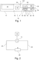
- FIG. 1 1 schematically shows an inhaler 10 or an electronic cigarette product.
- the inhaler 10 comprises a housing 11 in which an air duct 30 or vent is provided between at least one air inlet opening 231 and an air outlet opening 24 at a mouth end 32 of the cigarette product 10 .
- the mouth end 32 of the inhaler 10 designates the end at which the consumer pulls for the purpose of inhalation and thereby applies a negative pressure to the inhaler 10 and generates an air flow 34 in the air duct 30 .
- the inhaler 10 advantageously consists of a base part 16 and an evaporator-tank unit 20 which comprises an evaporator device 1 with an evaporator 60 which can be regulated using the method according to the invention, and a liquid reservoir 18 .
- the evaporator tank unit can be designed in particular in the form of an exchangeable cartridge.
- the liquid reservoir 18 can be refilled by the user of the inhaler 10 .
- the air sucked in through the air inlet opening 231 is guided in the air duct 30 to the at least one evaporator 60 .
- the evaporator 60 is connected or can be connected to the liquid reservoir 18 in which at least one liquid 50 is stored.
- a porous and/or capillary, liquid-conducting element 19 is advantageously arranged on an inlet side 61 of the evaporator 60 .
- An advantageous volume of the liquid reservoir 18 is in the range between 0.1 ml and 5 ml, preferably between 0.5 ml and 3 ml, more preferably between 0.7 ml and 2 ml or 1.5 ml.
- the vaporizer 60 vaporizes liquid 50, which is supplied to the vaporizer 60 from the liquid reservoir 18 by the porous element 19 by means of capillary forces and/or which is stored in the porous element 19, and releases the vaporized liquid as an aerosol/vapor at an outlet side 64 air flow 34 to.
- the inhaler 10 also includes an electrical energy store 14 and an electronic control device 15.
- the energy store 14 is usually arranged in the base part 16 and can in particular be an electrochemical disposable battery or a rechargeable electrochemical battery, for example a lithium-ion battery. be.
- the evaporator tank unit 20 is arranged between the energy store 14 and the mouth end 32 .
- the electronic control device 15 comprises at least one digital data processing device, in particular a microprocessor and/or microcontroller, in the base part 16 (as in figure 1 shown) and/or in the evaporator-tank unit 20.
- a sensor for example a pressure sensor or a pressure or flow switch, is advantageously arranged in the housing 11, wherein the control device 15 can determine on the basis of a sensor signal emitted by the sensor that a consumer pulls on the mouth end 32 of the cigarette product 10 in order to inhale.
- the control device 15 controls the evaporator 60 in order to add liquid 50 from the liquid reservoir 18 as an aerosol/vapor into the air flow 34 .
- the at least one evaporator 60 is arranged in a part of the evaporator-tank unit 20 that faces away from the mouth end 32 . Effective electrical coupling, in particular with the base part 16, and activation of the evaporator 60 are thus possible.
- the air flow 34 advantageously leads through an air duct 30 running axially through the liquid reservoir 18 to the air outlet opening 24.
- the liquid 50 to be metered stored in the liquid reservoir 18 is, for example, a mixture of 1,2-propylene glycol, glycerin, water, and preferably at least one flavor and/or at least one active substance, in particular nicotine.
- the specified components of the liquid 50 are not mandatory.
- flavorings and/or active substances, in particular nicotine can be dispensed with.
- the evaporator 60 is an electrical resistance heater that can be heated by an electrical current due to its electrical resistance.
- the evaporator 60 can have at least one resistance element, for example a heating wire, for example a spiral wire or one wire conductor or a plurality of wire conductors arranged parallel to one another.
- the evaporator 60 can alternatively be designed as a microelectromechanical system (MEMS), for example with ducts or microchannels, as in FIG DE 10 2016 120 803 A1 described, the disclosure content of which is incorporated into the present application.
- MEMS microelectromechanical system
- Bionic or capillary-like heating structures, such as bionic networks, are also possible for the evaporator 60 .
- the evaporator-tank unit 20 is preferably connected and/or can be connected to a heating current source 71 that can be controlled by the control device 15 and that is connected to the evaporator 60 via electrical lines 25, so that an electrical heating current Ih generated by the heating current source 71 flows through the evaporator 60 flows. Because of the ohmic resistance of the electrically conductive evaporator 60 , the current flow leads to the evaporator 60 being heated and therefore to the evaporation of liquid present on the evaporator 60 . Vapor/aerosol generated in this way escapes from the vaporizer 60 and is admixed with the air flow 34 . Specifically, upon detection of airflow caused by consumer puffing, 34 conducts the air duct 30, the control device 15, the heating current source 71, the liquid present at the evaporator 60 being emitted in the form of vapor/aerosol by spontaneous heating.
- the evaporation temperature is preferably in the range between 100°C and 400°C, more preferably between 150°C and 350°C, even more preferably between 190°C and 290°C.
- the evaporator tank unit 20 is adjusted so that a liquid quantity is preferably in the range between 1 ⁇ l and 20 ⁇ l, more preferably between 2 ⁇ l and 10 ⁇ l, even more preferably between 3 ⁇ l and 5 ⁇ l, typically 4 ⁇ l per puff of the consumer , is added.
- the evaporator-tank unit can be adjustable with regard to the amount of liquid/vapor per puff, i.e. per puff duration from 1 s to 3 s.
- the control frequency of the evaporator 60 generated by the heating current source 71 is generally advantageously in the range from 1 Hz to 50 kHz, preferably in the range from 30 Hz to 30 kHz, even more advantageously in the range from 100 Hz to 25 kHz.
- the evaporator 60 can be replaced when the substrate is dirty, defective or used up, so that a separable electrical connection can be provided between the evaporator 60 and the base part 16 .
- This connection can be designed as, for example, spring pins, a plug-in connection or a screw connection.
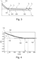
- figure 3 shows a schematic series of current measurements 100, indicated by a bold black curve, with a determined transition point 101 at a current I v , this representation showing a Example of a current measurement series 100 for an evaporator 60 with a negative temperature coefficient shows.
- the current I is plotted against the time t and is shown as continuous for illustrative purposes only.
- a puff at a starting point 110 which is determined, for example, by detecting the puff using a pressure sensor or by switching it on by a consumer, the evaporator 60 is switched on and heated with a heating current. This is followed by a chronologically sequential recording of measured values 108 (in figure 3 drawn schematically as a curve) of the current I applied to the evaporator 60 from the starting point 110.
- the evaporator 60 heats up relatively quickly, which is why the measured current I falls.
- the current measurement series 100 over time has a transition point 101 that can be recognized as a break point, or at least a strong flattening, which is determined as the transition point 101 as soon as the evaporation begins.
- Two-point control follows as a function of a current Iv associated with the transition point 101 with the lower threshold I 1 and the upper threshold I 2 , the current I in the current interval [I 1 ; I 2 ] is regulated: as soon as the determined current flow I exceeds the upper threshold I 2 , the current source is switched off or the current flow is reduced; as soon as the determined current flow I falls below the lower threshold I 2 , the current source is switched on or the current flow is increased.
- the difference between the upper threshold I 2 and the current I V at the transition point 102 and the difference between the current I V at the transition point 102 and the lower threshold I 1 is advantageously smaller than the current I V at the transition point 102, since there is no or only a slight excess temperature at the Evaporator 60 is to occur and therefore only a small change in current occurs.
- the advantage of the control method described above is illustrated by the lower series of current measurements 200 in figure 3 clarified.
- the lower series of current measurements 200 shows a current curve for an evaporator 60 that differs in one or more points from the evaporator 60 of the series of current measurements 100 printed in bold: the battery voltage is different, in particular due to the state of discharge or internal resistance; the heating resistance of the evaporator 60 is different, in particular due to manufacturing tolerances; other electrical resistances are present.
- a transition point 201 for the lower series of current measurements 200 at a different current I w which, however, arises again when evaporation begins.
- a lower threshold I 1 and an upper threshold I 2 can easily be chosen, within which the current I is regulated, so that the vaporizer 60 reliably and effectively vaporizes liquid.
- the method according to the invention results in a temperature error that is one order of magnitude smaller than in the case of resistive temperature determination according to the prior art. It is advantageous if the magnitude of the current interval
- the process does not regulate to a fixed temperature, but to a current that corresponds to the evaporation temperature or a temperature slightly above the evaporation temperature. Since the vaporization temperature depends on the composition of the substrate or, in particular, the liquid, the temperature is not absolute, but the current I V leading to the evaporation is determined.
- the series of current measurements 100 includes a plurality of measured values 108 recorded consecutively in time, which are represented by a corresponding number of points, each point representing a measured value 108 with an associated current I at a time t.
- the control device 15 calculates a regression line 102 from the measured values 108, for example using linear regression.
- two different regression lines 102 are shown at the times t 1 and t 2 .
- the time profile of the rise 109 of the regression line 102 determined in this way is in figure 5 shown.
- the regression has the advantage that the transition point 101 can be localized well, even if the series of current measurements 100 is overlaid with noise.
- the regression thus smoothes the slope 109 and offers an improvement over finite differences.
- figure 5 shows a determination of a transition point 101 based on the increase 109 in figure 4 Current measurement series 100 shown.
- the transition point 101 can be detected in real time by evaluating the first or second time derivative of the current I.
- the increase 109 is the increase in the regression line 102 determined by regression on the current measurement series 100 and is plotted against the time t. For example, if the magnitude of the increase 109 falls below a threshold value 103, it can be concluded that evaporation has started.
- the transition point 101 is where the magnitude of the slope 109 of the regression line 102 is less than a threshold value 103 of 0.002 A/s in this example.
- the threshold 103 can be determined empirically for the evaporator 60 . From the time t 0 at which the rise 109 exceeds the threshold value 103, the evaporation current I V can be determined using the series of current measurements 100, here for example approx. 2.6 A (cf figure 4 ).
- figure 6 shows a determination of a transition point 101 based on the curvature 106 of the figure 4 current measurement series 100 shown.
- An extreme value 107 in the second derivative in particular a maximum, characterizes the transition point 101.
- the transition point 101 or the evaporation point of the current measurement series 101 can also be found via the curvature 106 of the current measurement series 100.
- a polynomial in particular of the second order, is locally fitted to a plurality of successive measured values 108 of the current measurement series 100 along the current measurement series 100 instead of a regression line 102 .
- the coefficient of the squared term of the polynomial is determined as curvature 106 and plotted against time t.
- An algorithm for finding an extreme value 107 finds the extreme value 107 at a time t 0 , which corresponds to the time at which the current measurement series 100 has the transition point 101 .
Landscapes
- Measuring Volume Flow (AREA)
- Investigating Or Analyzing Materials Using Thermal Means (AREA)
- Control Of Resistance Heating (AREA)
Description
- Die vorliegende Erfindung betrifft Verfahren zur Regelung der Verdampfung eines Verdampfers in einem Inhalator, wobei der Verdampfer mittels elektrischer Widerstandsheizung geheizt wird, und wobei eine elektronische Steuerungseinrichtung den Stromfluss durch den Verdampfer regelt.
- Typischerweise wird ein resistiver Verdampfer über ein elektronisches Schaltelement mit einem Energiespeicher elektrisch verbunden, sodass bei geschlossenem Schaltelement die Spannung des Energiespeichers am Verdampfer anliegt und ein Heizstrom fließt. Der Schalter wird üblicherweise durch die elektronische Steuereinrichtung betrieben.
- Die Temperatur am Verdampfer wird typischerweise mithilfe eines temperaturabhängigen elektrischen Widerstands des Verdampfers ermittelt. Durch die Beziehung zwischen Temperatur und dem elektrischen Widerstand des Verdampfers kann die Temperatur des Verdampfers gezielt eingestellt werden. Die Temperatur sollte dabei eine durch die zu verdampfende Flüssigkeit bestimmte Temperatur nicht übersteigen, da sonst Schadstoffe entstehen können, insbesondere durch ein Trockenfallen des Verdampfers.
- Der Stromkreis eines Verdampfers bzw. Heizers lässt sich vereinfacht als eine Reihenschaltung von elektrischen Widerständen beschreiben. Elemente dieser Reihenschaltung umfassen einen elektrischen Widerstand des Verdampfers (Verdampferwiderstand), einen Batterieinnenwiderstand sowie unerwünschte parasitäre elektrische Widerstände. Die parasitären Widerstände sind beispielsweise durch folgende Widerstände gegeben: einen zu der elektrischen Steuerungseinrichtung gehörigen elektrischen Widerstand, einen Strommesswiderstand, einen elektrischen Widerstand der Zuleitungen, insbesondere durch Verbindungsdrähte, Kupferleitbahnen und/oder Lötstellen und gegebenenfalls einen elektrischen Widerstand einer möglichen Steckverbindung. Der parasitäre Widerstand ist weder zeitlich konstant noch reproduzierbar, da beispielsweise Steckverbindungen je nach Alterungszustand, Verschmutzung und/oder Verformung einen nur mit erheblichem Aufwand messbaren Einfluss auf den parasitären Widerstand haben.
- Temperaturmessfehler aufgrund parasitärer Widerstände können zu einer Überhitzung der zu verdampfende Flüssigkeit führen, was zu Blasensieden oder Schadstoffentstehung führen kann. Aufgrund der vielfältigen, durch Messung und parasitäre Ströme bedingten Fehler kann der Verdampfer nur unzureichend mit bekannten Verfahren geregelt werden.
-
WO 2018/122410 A1 offenbart ein Verfahren zur Regelung der Verdampfung eines Verdampfers in einem Inhalator nach dem Oberbegriff von Anspruch 1. - Es ist die Aufgabe der Erfindung, ein Verfahren bereitzustellen, mit dem die Verdampfung effektiv und zuverlässig geregelt und eine Überhitzung der zu verdampfende Flüssigkeit sicher vermieden werden kann.
- Erfindungsgemäß umfasst das Verfahren folgende Schritte: Zeitlich aufeinanderfolgendes Aufnehmen von Messwerten des an dem Verdampfer anliegenden Stroms ab einem Anfangspunkt. Ab dem Anfangspunkt fließt ein Strom durch den Verdampfer. Durch den Stromfluss und den temperarturabhängigen elektrischen Widerstand des Verdampfers erwärmt sich der Verdampfer. Aufgrund der Erwärmung des Verdampfers verändert sich der temperarturabhängige elektrische Widerstand des Verdampfers.
- Die Messung kann vorteilhaft durch eine Bedarfsanforderung eines Benutzers des Inhalators eingeschaltet werden, insbesondere durch ein Ziehen an einer elektronischen Zigarette. Entsprechend kann die Messung nach Beendigung der Anforderung ausgeschaltet werden.
- Nachfolgend wird ein Übergangspunkts zwischen einem Bereich geringer und insbesondere bis hin zu keiner Verdampfung und einem Bereich hoher Verdampfung insbesondere während des Konsums in einer den Messwerten entsprechenden zeitabhängigen Strommessreihe bestimmt. Der Übergangspunkt markiert den Zeitpunkt, zu der die Verdampfung eintritt und der Verdampfer nicht wesentlich weiter erwärmt wird. Die Erfindung hat erkannt, dass ab dem Übergangspunkt Verdampfung in einem solchen hohen Maße stattfindet, dass keine oder kaum eine weitere Erwärmung des Verdampfers mehr stattfindet. Die durch den Stromfluss am Verdampfer bereitgestellte Energie wird in Energie zur Verdampfung der Flüssigkeit und nicht oder nur zu geringen Anteilen in die Erwärmung des Verdampfers umgewandelt. Daher ändert sich ab dem Übergangspunkt die Temperatur des Verdampfers in einem geringeren Maß als zu der Zeit vor dem Übergangspunkt. Damit kann der Übergangspunkt in der Strommessreihe als ein Knickpunkt in der Abhängigkeit zwischen Strom und Messpunkt beziehungsweise Zeit verstanden werden. Aus dem Übergangspunkt erfolgt eine Ermittlung eines dem Übergangspunkt entsprechenden Stromwerts Iv, bei dem eine zuverlässige Verdampfung stattfindet. Zur Regelung der Heizleistung über den Stromfluss folgt ein Festlegen eines Stromintervalls [I1; I2] in Abhängigkeit von dem ermittelten Stromwert Iv und eine Regelung des Stromflusses innerhalb des festgelegten Stromintervalls [I1; I2]. Damit kann die Leistung des Verdampfers präzise geregelt werden.
- Das erfindungsgemäße Verfahren hat den Vorteil, dass die Verdampfertemperatur nicht bekannt sein muss und der Wert insbesondere des parasitären elektrischen Widerstands nicht in Echtzeit und für jeden individuellen Verdampfer bestimmt zu werden braucht. Mit dem erfindungsgemäßen Verfahren ist entscheidend, bei welchem jeweiligen Strom beziehungsweise welcher Heizleistung die Verdampfung durch den jeweiligen Verdampfer eintritt. Der Eintritt der Verdampfung wird anhand der Messreihe bestimmt und bestimmt somit den anzulegenden Heizstrom innerhalb des Stromintervalls [I1; I2].
- Vorteilhaft wird der Übergangspunkt anhand einer Regression entlang der Strommessreihe ermittelt, um den Übergangspunkt zuverlässig und effektiv bestimmen zu können. Einer Regression liegen eine Mehrzahl von Messwerten zu Grunde, womit Messfehler und/oder statistische Fehler minimiert werden können. Die Regression ist vorteilhaft gegenüber beispielsweise einer Finite Differenzen-Methode, bei der lediglich insbesondere zwei benachbarte Messwerte betrachtet werden und sich so eine Messungenauigkeit besonders stark auf das Ergebnis auswirkt.
- Vorzugsweise wird der Übergangspunkts mindestens einer Ausgleichsgeraden und/oder mindestens eines Ausgleichspolynoms an die Strommessreihe ermittelt, um eine numerisch effektive Ermittlung des Übergangspunkts bereitzustellen. Beispielsweise können ein oder mehrere Ausgleichsgeraden und/oder insbesondere quadratische Ausgleichskurven an verschiedenen Messpunkten der Messreihe durch die Regression ermittelt werden. Aus dem zeitlichen Verlauf der zu den Ausgleichsgeraden gehörigen Anstiege beziehungsweise den zu den Ausgleichskurven gehörigen Krümmungen kann der Übergangspunkt ermittelt werden. Die Krümmung kann dabei insbesondere aus einem Koeffizienten eines quadratischen Terms des Ausgleichspolynoms bestimmt werden.
- Bevorzugt wird der Übergangspunkt durch einen Sprung und/oder das Erreichen eines Schwellwerts des Anstiegs bzw. der Steigung (1. Ableitung) der Strommessreihe ermittelt, um die Identifizierung des Übergangspunkts weiter zu verbessern. In einer vorteilhaften Ausführungsform wird dazu der Übergangspunkt durch einen Extremwert der Krümmung der Strommessreihe ermittelt.
- Vorzugsweise sind zwei zeitlich aufeinanderfolgende Messwerte weniger als 10 ms, vorzugsweise weniger als 5 ms, weiter vorzugsweise weniger als 2 ms zeitlich voneinander beabstandet, um den Übergangspunkt zeitlich gut auflösen zu können und über die Dauer eines Zuges eine vorteilhafte Anzahl an Messwerten aufnehmen zu können. Dazu werden bevorzugt die aufgenommenen Messwerte wenigstens über 10%, vorteilhaft wenigstens 30%, weiter vorteilhaft wenigstens 50% einer Zuglänge aufgenommen.
- Vorteilhaft ist die Länge des Stromintervalls [I1; I2] kleiner als 50%, vorteilhaft kleiner als 25%, weiter vorteilhaft kleiner als 10% des Betrages des Stromwerts Iv, damit der Heizstrom möglichst genau geregelt werden kann.
- in einer bevorzugten Ausführungsform wird die untere Schwelle I1 und/oder die obere Schwelle I2 so festgelegt, dass die untere Schwelle kleiner als der Stromwert IV und/oder der Stromwert IV kleiner als die obere Schwelle I2 sind, damit der Heizstrom zuverlässig um den Stromwert IV in dem Stromintervall [I1; I2] geregelt werden kann. Ist die untere Schwelle I1 kleiner als der Stromwert IV, kann ein Trockenfallen des Verdampfers verhindert werden, da der Verdampfer mit einem Strom zwischen der unteren Schwelle I1 und dem Stromwert IV\ nicht verdampft, sondern den Verdampfer und/oder die Flüssigkeit heizt.
- Vorzugsweise wird der Stromfluss durch den Verdampfer gepulst, wobei das Tastverhältnis bei Erreichen der unteren Schwelle I1, von oben erhöht und/oder bei Erreichen der oberen Schwelle I2 von unten reduziert wird. Damit kann eine Reduktion der Eingangsleistung und eine Verlängerung der Laufzeit einer den Verdampfer mit elektrischem Strom versorgenden Batterie erzielt werden.
- Vorteilhaft wird die untere Schwelle I1, und/oder die obere Schwelle I2 in Abhängigkeit einer Analyse des durchschnittlichen quadratischen Stroms I^2 über ein definiertes Zeitintervall festgelegt. Fällt der durchschnittlichen quadratischen Strom I^2 unter einen vorgegebenen Schwellwert, der beispielsweise aus der Strommessreihe aus einem Zeitintervall nach dem Anfangspunkt bestimmt werden kann, so ist dies als Zeichen für einen verringerten Kontakt zwischen dem Verdampfer und der Flüssigkeit zu werten. In diesem Fall sollten die untere Schwelle I1 und/oder die obere Schwelle I2 zu niedrigeren Strömen verschoben werden.
- Bevorzugt wird das Stromintervall [h; I2] und/oder mindestens eine der Schwellen I1; I2 im Laufe der Zeit zu niedrigeren Strömen verschoben, um einem Trockenfallen des Verdampfers vorzubeugen. Das Stromintervall [I1; I2] und/oder mindestens eine der Schwellen I1; I2 können auch an eine vorgegebene Zeitfunktion angepasst werden, um die Verdampfung effektiv kontrollieren zu können und eine Anpassung an Vorgänge der differenziellen Destillation zu ermöglichen.
- In einer vorteilhaften Ausführungsform werden Daten bezüglich mehrerer zeitabhängiger Strommessreihen in einem Datenspeicher gespeichert und miteinander und/oder mit festen Parametern verglichen. Damit ist es möglich, die im Laufe des Verfahrens angefallenen Strommesswerte und Übergangspunkte zu speichern. Eine automatische Analyse kann beispielsweise untersuchen, zu welchem Zeitpunkt der Verdampfungsstrom IV erreicht wurde. Wird dieser Zeitpunkt später als ein vorgegebener Schwellwert erreicht, so ist dies ein Hinweis auf einen zu hohen elektrischen Widerstand. Weiterhin kann das durchschnittliche Stromquadrat während des Verdampfungsvorgangs ausgewertet werden. ist dies niedriger als ein vorgegebener Schwellwert, so kann auf den Verbrauch der Flüssigkeit zurückgeschlossen werden.
- Vorzugsweise wird die Umgebungstemperatur gemessen, und das Stromintervall [I1; I2] und/oder wenigstens eine seiner Schwellen I1, I2 wird in Abhängigkeit der gemessenen Umgebungstemperatur festgelegt und/oder angepasst, um mögliche Einflüsse der Umgebungstemperatur berücksichtigt zu können.
- Vorteilhaft erfolgt die Regelung des Stromflusses durch ein Einschalten und/oder Beibehalten des Stromflusses durch den Verdampfer bei einem Strom von weniger als einem oberen Schwellwert I2, oder Ausschalten des Stromflusses durch den Verdampfer bei einem Strom mehr als einem unteren Schwellwert I1, um ein effektives Regelverfahren innerhalb des Stromintervalls [I1; I2] bereitstellen zu können.
- Die Erfindung wird im Folgenden anhand bevorzugter Ausführungsformen unter Bezugnahme auf die beigefügten Figuren erläutert. Dabei zeigt
- Fig. 1
- eine schematische Darstellung eines Inhalators;
- Fig. 2
- eine vereinfachte Schaltung zur Stromheizung eines Verdampfers;
- Fig. 3
- eine schematische Strommessreihe mit einem ermittelten Übergangspunkt;
- Fig. 4
- eine exemplarische Strommessreihe mit einem Übergangspunkt;
- Fig. 5
- die Ermittlung eines Übergangspunkts anhand des Anstiegs einer Strommessreihe; und
- Fig. 6
- die Ermittlung eines Übergangspunkts anhand der Krümmung einer Strommessreihe.
-
Figur 1 zeigt schematisch einen Inhalator 10 beziehungsweise ein elektronisches Zigarettenprodukt. Der Inhalator 10 umfasst ein Gehäuse 11, in dem ein Luftkanal 30 beziehungsweise Schlot zwischen mindestens einer Lufteinlassöffnung 231 und einer Luftauslassöffnung 24 an einem Mundende 32 des Zigarettenprodukts 10 vorgesehen ist. Das Mundende 32 des Inhalators 10 bezeichnet dabei das Ende, an dem der Konsument zwecks Inhalation zieht, und dadurch den Inhalator 10 mit einem Unterdruck beaufschlagt und einen Luftstrom 34 in dem Luftkanal 30 erzeugt. - Der Inhalator 10 besteht vorteilhaft aus einem Basisteil 16 und einer Verdampfer-Tank-Einheit 20, die eine Verdampfervorrichtung 1 mit einem Verdampfer 60, der durch das erfindungsgemäße Verfahren regelbar ist, und einen Flüssigkeitsspeicher 18 umfasst. Die Verdampfer-Tank-Einheit kann insbesondere in Form einer auswechselbaren Kartusche ausgebildet sein. Der Flüssigkeitsspeicher 18 kann von dem Nutzer des Inhalators 10 nachfüllbar sein. Die durch die Lufteinlassöffnung 231 angesaugte Luft wird in dem Luftkanal 30 zu dem mindestens einen Verdampfer 60 geleitet. Der Verdampfer 60 ist mit dem Flüssigkeitsspeicher 18 verbunden oder verbindbar, in dem mindestens eine Flüssigkeit 50 gespeichert ist. Dazu ist vorteilhaft an einer Einlassseite 61 des Verdampfers 60 ein poröses und/oder kapillares, flüssigkeitsleitendes Element 19 angeordnet.
- Ein vorteilhaftes Volumen des Flüssigkeitsspeichers 18 liegt im Bereich zwischen 0,1 ml und 5 ml, vorzugsweise zwischen 0,5 ml und 3 ml, weiter vorzugsweise zwischen 0,7 ml und 2 ml oder 1,5 ml.
- Der Verdampfer 60 verdampft Flüssigkeit 50, die dem Verdampfer 60 aus dem Flüssigkeitsspeicher 18 von dem porösen Element 19 mittels Kapillarkräften zugeführt wird und/oder die in dem porösen Element 19 gespeichert ist, und gibt die verdampfte Flüssigkeit als Aerosol/Dampf an einer Auslassseite 64 den Luftstrom 34 zu.
- Der Inhalator 10 umfasst des Weiteren einen elektrischen Energiespeicher 14 und eine elektronische Steuerungsvorrichtung 15. Der Energiespeicher 14 ist in der Regel in dem Basisteil 16 angeordnet und kann insbesondere eine elektrochemische Einweg-Batterie oder ein wiederaufladbarer elektrochemischer Akku, beispielsweise ein Lithium-Ionen-Akku, sein. Die Verdampfer-Tank-Einheit 20 ist zwischen dem Energiespeicher 14 und dem Mundende 32 angeordnet.
- Die elektronische Steuerungsvorrichtung 15 umfasst mindestens eine digitale Datenverarbeitungseinrichtung, insbesondere Mikroprozessor und/oder Microcontroller, in dem Basisteil 16 (wie in
Figur 1 gezeigt) und/oder in der Verdampfer-Tank-Einheit 20. - In dem Gehäuse 11 ist vorteilhaft ein Sensor, beispielsweise ein Drucksensor oder ein Druck- oder Strömungsschalter, angeordnet, wobei die Steuerungsvorrichtung 15 auf der Grundlage eines von dem Sensor ausgegebenen Sensorsignals feststellen kann, dass ein Konsument am Mundende 32 des Zigarettenprodukts 10 zieht, um zu inhalieren. In diesem Fall steuert die Steuerungsvorrichtung 15 den Verdampfer 60 an, um Flüssigkeit 50 aus dem Flüssigkeitsspeicher 18 als Aerosol/Dampf in den Luftstrom 34 zuzugeben.
- Der mindestens eine Verdampfer 60 ist in einem dem Mundende 32 abgewandten Teil der Verdampfer-Tank-Einheit 20 angeordnet. Damit sind eine effektive elektrische Kopplung insbesondere mit dem Basisteil 16 und Ansteuerung des Verdampfers 60 möglich. Der Luftstrom 34 führt vorteilhaft durch einen axial durch den Flüssigkeitsspeicher 18 laufenden Luftkanal 30 zu der Luftauslassöffnung 24.
- Die in dem Flüssigkeitsspeicher 18 gespeicherte, zu dosierende Flüssigkeit 50 ist beispielsweise eine Mischung aus 1,2-Propylenglykol, Glycerin, Wasser, und vorzugsweise mindestens einem Aroma (Flavour) und/oder mindestens einem Wirkstoff, insbesondere Nikotin. Die angegebenen Bestandteile der Flüssigkeit 50 sind jedoch nicht zwingend. Insbesondere kann auf Aroma- und/oder Wirkstoffe, insbesondere Nikotin, verzichtet werden.
- In
Figur 2 ist eine schematische Schaltung zur Stromheizung des Verdampfers 60 gezeigt. Der Verdampfer 60 ist ein elektrischer Widerstandsheizer, der durch einen elektrischen Strom aufgrund seines elektrischen Widerstands erwärmt werden kann. Der Verdampfer 60 kann mindestens ein Widerstandselement, beispielsweise einen Heizdraht aufweisen, beispielsweise einen Spiraldraht oder einen oder eine Mehrzahl parallel zueinander angeordneter Drahtleiter. Der Verdampfer 60 kann alternativ als mikroelektromechanisches System (MEMS) ausgeführt sein, beispielsweise mit Leitungs- oder Mikrokanälen, wie in derDE 10 2016 120 803 A1 beschrieben, deren Offenbarungsgehalt insoweit in die vorliegende Anmeldung aufgenommen wird. Auch bionische oder kapillarartige Heizstrukturen, wie bionische Netze, sind für den Verdampfer 60 möglich. Es sind auch Verdampfer 60 mit Heizstrukturen wie in derDE 10 2017 111 119 A1 beschrieben möglich, deren Offenbarungsgehalt insoweit in die vorliegende Anmeldung aufgenommen wird. Generell ist die Erfindung nicht an einen bestimmten Typ von Verdampfer 60 gebunden. - Die Verdampfer-Tank-Einheit 20 ist vorzugsweise mit einer von der Steuerungsvorrichtung 15 steuerbaren Heizstromquelle 71 verbunden und/oder verbindbar, die über elektrische Leitungen 25 mit dem Verdampfer 60 verbunden ist, so dass ein von der Heizstromquelle 71 erzeugter elektrischer Heizstrom Ih durch den Verdampfer 60 fließt. Aufgrund des ohmschen Widerstands des elektrisch leitenden Verdampfers 60 führt der Stromfluss zu einer Erhitzung des Verdampfers 60 und daher zu einer Verdampfung von an dem Verdampfer 60 anliegender Flüssigkeit. Auf diese Weise erzeugter Dampf/Aerosol entweicht aus dem Verdampfer 60 und wird dem Luftstrom 34 beigemischt. Genauer steuert bei Feststellung eines durch Ziehen des Konsumenten verursachten Luftstroms 34 durch den Luftkanal 30 die Steuerungsvorrichtung 15 die Heizstromquelle 71 an, wobei durch spontane Erhitzung die an dem Verdampfer 60 anliegende Flüssigkeit in Form von Dampf/Aerosol ausgegeben wird.
- Die Verdampfungstemperatur liegt vorzugsweise im Bereich zwischen 100 °C und 400 °C, weiter bevorzugt zwischen 150 °C und 350 °C, noch weiter bevorzugt zwischen 190 °C und 290 °C.
- Die Verdampfer-Tank-Einheit 20 ist so eingestellt, dass eine Flüssigkeitsmenge vorzugsweise im Bereich zwischen 1 µl und 20 µl, weiter vorzugsweise zwischen 2 µl und 10 µl, noch weiter vorzugsweise zwischen 3 µl und 5 µl, typischerweise 4 µl pro Zug des Konsumenten, zudosiert wird. Vorzugsweise kann die Verdampfer-Tank-Einheit hinsichtlich der Flüssigkeits-/Dampfmenge pro Zug, d.h. je Zugdauer von 1 s bis 3 s, einstellbar sein.
- Die von der Heizstromquelle 71 erzeugte Ansteuerfrequenz des Verdampfers 60 liegt im Allgemeinen vorteilhaft im Bereich von 1 Hz bis 50 kHz, bevorzugt im Bereich von 30 Hz bis 30 kHz, noch weiter vorteilhaft im Bereich von 100 Hz bis 25 kHz.
- Vorteilhaft kann der Verdampfer 60 bei Verschmutzung, Defekt oder aufgebrauchtem Substrat ersetzbar sein, sodass eine trennbare elektrische Verbindung zwischen dem Verdampfer 60 dem Basisteil 16 vorgesehen sein kann. Diese Verbindung kann als beispielsweise Federstifte, Steck- oder Schraubverbindung ausgeführt sein.
-
Figur 3 zeigt eine durch eine fette schwarze Kurve angedeutete schematische Strommessreihe 100 mit einem ermittelten Übergangspunkt 101 bei einem Strom Iv, wobei diese Darstellung ein Beispiel einer Strommessreihe 100 für einen Verdampfer 60 mit einem negativen Temperaturkoeffizienten zeigt. InFigur 3 ist der Strom I gegen die Zeit t aufgetragen und nur zur Anschauung als kontinuierlich dargestellt. - Zu Beginn eines Zuges an einem Anfangspunkt 110, der beispielsweise durch das Feststellen des Zuges mittels eines Drucksensors ermittelt oder durch ein Einschalten durch einen Konsumenten bestimmt wird, wird der Verdampfer 60 eingeschaltet und mit einem Heizstrom beheizt. Nun folgt ein zeitlich aufeinanderfolgendes Aufnehmen von Messwerten 108 (in
Figur 3 schematisch als Kurve gezeichnet) des an dem Verdampfer 60 anliegenden Stroms I ab dem Anfangspunkt 110. Der Verdampfer 60 heizt sich relativ schnell auf, daher fällt der gemessene Strom I ab. - Die zeitliche Strommessreihe 100 weist einen als Knickpunkt erkenntlichen Übergangspunkt 101 oder zumindest aber eine starke Abflachung auf, die als Übergangspunkt 101 bestimmt wird, sobald die Verdampfung einsetzt. Es folgt eine Zweipunktregelung in Abhängigkeit von einem zum Übergangspunkt 101 gehörigen Strom Iv mit der unteren Schwelle I1 und der oberen Schwelle I2, wobei der Strom I in dem Stromintervall [I1; I2] geregelt wird: sobald der ermittelte Stromfluss I die obere Schwelle I2 überschreitet, wird die Stromquelle ausgeschaltet oder der Stromfluss reduziert; sobald der ermittelte Stromfluss I die untere Schwelle I2 unterschreitet, wird die Stromquelle eingeschaltet oder der Stromfluss erhöht. Die Differenz der oberen Schwelle I2 zu dem Strom IV am Übergangspunkt 102 und die Differenz des Stroms IV am Übergangspunkt 102 zu der unteren Schwelle I1 ist vorteilhaft kleiner als der Strom IV am Übergangspunkt 102, da keine oder nur eine geringe Übertemperatur am Verdampfer 60 auftreten soll und somit auch nur eine geringe Stromänderung auftritt.
- Der Vorteil des zuvor beschriebenen Verfahrens zur Regelung wird anhand der unteren Strommessreihe 200 in
Figur 3 verdeutlicht. Die untere Strommessreihe 200 zeigt einen Stromverlauf für einen Verdampfer 60 der sich in einem oder mehreren Punkten vom Verdampfer 60 der fett gedruckten Strommessreihe 100 unterscheidet: die Batteriespannung ist eine andere, insbesondere durch den Entladungszustand oder Innenwiderstand; der Heizwiderstand des Verdampfers 60 ist ein anderer, insbesondere durch Fertigungstoleranzen; andere elektrische Widerstände liegen vor. - Somit ergibt sich für die untere Strommessreihe 200 ein Übergangspunkt 201 bei einem anderen Strom Iw, der jedoch wieder beim Einsetzen der Verdampfung entsteht. In diesem Beispiel können leicht eine untere Schwelle I1 und eine obere Schwelle I2 gewählt werden, innerhalb denen der Strom I geregelt wird, damit der Verdampfer 60 zuverlässig und effektiv Flüssigkeit verdampft.
- Mit dem erfindungsgemäßen Verfahren ergibt sich ein Temperaturfehler, der um eine Größenordnung geringer ist als im Fall der resistiven Temperaturbestimmung gemäß dem Stand der Technik. Dabei ist es von Vorteil, wenn der Betrag des Stromintervalls |I2-I1| kleiner als 50 %, vorteilhaft kleiner als 25 %, weiter vorteilhaft kleiner als 10 % des Betrages des Stromwerts Iv ist. Das Verfahren regelt nicht auf eine feste Temperatur, sondern auf einen Strom, der der Verdampfungstemperatur oder einer Temperatur etwas oberhalb der Verdampfungstemperatur entspricht. Da die Verdampfungstemperatur von der Zusammensetzung des Substrats beziehungsweise insbesondere der Flüssigkeit abhängt, ist die Temperatur nicht absolut, sondern der zur Verdampfung führende Strom IV wird bestimmt.
-
Figur 4 zeigt eine exemplarische Strommessreihe 100 einer möglichen Messkurve mit einem Übergangspunkt 101 bei einer Zeit von etwa t = 201 ms und einem realistischen Rauschen des Stromsignals. Die Strommessreihe 100 umfasst mehrere zeitlich aufeinanderfolgend aufgenommene Messwerte 108, die durch eine entsprechende Anzahl von Punkten dargestellt sind, wobei jeder Punkt einem Messwert 108 mit einem zugehörigen Strom I zu einer Zeit t repräsentiert. - Sobald n Werte aufgenommen sind, berechnet die Steuerungseinrichtung 15 aus den Messwerten 108 beispielsweise per linearer Regression eine Ausgleichsgerade 102. In diesem Beispiel sind zwei verschiedene Ausgleichsgeraden 102 zu den Zeitpunkten t1 und t2 gezeigt. Der zeitliche Verlauf des Anstiegs 109 der damit ermittelten Ausgleichsgeraden 102 ist in
Figur 5 gezeigt. - Die Regression hat den Vorteil, dass sich der Übergangspunkt 101 gut lokalisieren lässt, selbst wenn die Strommessreihe 100 mit Rauschen überlagert ist. Die Regression glättet somit den Anstieg 109 und bietet eine Verbesserung gegenüber Finiten Differenzen.
-
Figur 5 zeigt eine Ermittlung eines Übergangspunkts 101 anhand des Anstiegs 109 der inFigur 4 gezeigten Strommessreihe 100. Der Übergangspunkt 101 kann durch Auswertung der ersten oder zweiten zeitlichen Ableitung des Stroms I in Echtzeit detektiert werden. - Der Anstieg 109 ist der Anstieg der durch Regression an der Strommessreihe 100 ermittelten Ausgleichsgeraden 102 und ist in gegen die Zeit t aufgetragen. Fällt beispielsweise der Betrag des Anstiegs 109 unter einen Schwellwert 103, kann auf ein Einsetzen der Verdampfung geschlossen werden. In diesem Beispiel befindet sich der Übergangspunkt 101 dort, wo der Betrag des Anstiegs 109 der Ausgleichsgeraden 102 kleiner als ein Schwellwert 103 von in diesem Beispiel 0,002 A/s ist. Der Schwellwert 103 kann empirisch für den Verdampfer 60 bestimmt werden. Aus der Zeit t0, zu der der Anstieg 109 den Schwellwert 103 überschreitet, kann anhand der Strommessreihe 100 der Verdampfungsstrom IV bestimmt werden, hier beispielsweise ca. 2,6 A (vergleiche
Figur 4 ). -
Figur 6 zeigt eine Ermittlung eines Übergangspunkts 101 anhand der Krümmung 106 der inFigur 4 gezeigten Strommessreihe 100. Ein Extremwert 107 in der zweiten Ableitung, insbesondere ein Maximum, kennzeichnet den Übergangspunkt 101. Der Übergangspunkt 101 bzw. der Verdampfungspunkt der Strommessreihe 101 kann auch über die Krümmung 106 der Strommessreihe 100 gefunden werden. Dafür wird entlang der Strommessreihe 100 anstelle einer Ausgleichsgeraden 102 ein Polynom, insbesondere zweiter Ordnung, an eine Mehrzahl aufeinanderfolgender Messwerte 108 der Strommessreihe 100 lokal gefittet. Der Koeffizient des quadratischen Terms des Polynoms wird als Krümmung 106 bestimmt und gegen die Zeit t aufgetragen. Ein Algorithmus zum Auffinden eines Extremwerts 107 findet den Extremwert 107 bei einem Zeitpunkt t0, der dem Zeitpunkt entspricht, an dem die Strommessreihe 100 den Übergangspunkt 101 aufweist. -
- 1
- Verdampfervorrichtung
- 4
- Träger
- 10
- Inhalator
- 11
- Gehäuse
- 14
- Energiespeicher
- 15
- Steuerungseinrichtung
- 16
- Basisteil
- 18
- Flüssigkeitsspeicher
- 19
- Dochtstruktur
- 20
- Verdampfer-Tank-Einheit
- 24
- Luftauslassöffnung
- 30
- Luftkanal
- 32
- Mundende
- 34
- Luftstrom
- 50
- Flüssigkeit
- 60
- Verdampfer
- 61
- Einlassseite
- 62
- Flüssigkeitskanal
- 64
- Auslassseite
- 71
- Heizstromquelle
- 100, 200
- Strommessreihe
- 101, 201
- Übergangspunkt
- 102
- Ausgleichsgerade
- 103
- Schwellwert
- 104
- Durchgangsöffnung
- 105a, 105b
- elektrische Leitung
- 106
- Krümmung
- 107
- Extremwert
- 108
- Messwert
- 109
- Anstieg
- 110
- Anfangspunkt
- 131
- Kontaktbereich
- 231
- Lufteinlassöffnung
- I, Iv, Iw
- Stromwert
- I1
- untere Schwelle
- I2
- obere Schwelle
- t0, t1, t2
- Zeitpunkt
Claims (15)
- Verfahren zur Regelung der Verdampfung eines Verdampfers (60) in einem Inhalator (10), wobei der Verdampfer (60) mittels elektrischer Widerstandsheizung geheizt wird, und wobei eine elektronische Steuerungseinrichtung (15) den Stromfluss durch den Verdampfer (60) regelt, gekennzeichnet durch folgende Schritte:- zeitlich aufeinanderfolgendes Aufnehmen von Messwerten (108) des an dem Verdampfer (60) anliegenden Stroms ab einem Anfangspunkt (110);- Bestimmung eines Übergangspunkts (101) zwischen einem Bereich geringer Verdampfung und einem Bereich hoher Verdampfung in einer den Messwerten (108) entsprechenden zeitabhängigen Strommessreihe (100);- Ermittlung, vorzugsweise in Echtzeit, eines dem Übergangspunkt (101) entsprechenden Stromwerts Iv;- Festlegen eines Stromintervalls [I1; I2] in Abhängigkeit von dem ermittelten Stromwert Iv; und- Regelung des Stromflusses innerhalb des festgelegten Stromintervalls [I1; I2].
- Verfahren nach Anspruch 1, dadurch gekennzeichnet, dass- der Übergangspunkts (101) anhand einer Regression an die Strommessreihe (100) ermittelt wird.
- Verfahren nach Anspruch 2, dadurch gekennzeichnet, dass- der Übergangspunkts (101) anhand mindestens einer Ausgleichsgerade und/oder mindestens eines Ausgleichspolynoms an die Strommessreihe (100) ermittelt wird.
- Verfahren nach einem der vorangehenden Ansprüche, dadurch gekennzeichnet, dass- der Übergangspunkt (101) durch einen Sprung und/oder das Erreichen eines Schwellwerts (103) des Anstiegs (109) der Strommessreihe (100) ermittelt wird.
- Verfahren nach einem der vorangehenden Ansprüche, dadurch gekennzeichnet, dass- der Übergangspunkt (101) durch einen Extremwert (107) der Krümmung (106) der Strommessreihe (100) ermittelt wird.
- Verfahren nach einem der vorangehenden Ansprüche, dadurch gekennzeichnet, dass- zwei zeitlich aufeinanderfolgende Messwerte (108) weniger als 10 ms, vorzugsweise weniger als 5 ms, weiter vorzugsweise weniger als 2 ms zeitlich voneinander beabstandet sind.
- Verfahren nach einem der vorangehenden Ansprüche, dadurch gekennzeichnet, dass- die aufgenommenen Messwerte (108) wenigstens über 10%, vorteilhaft wenigstens 30%, weiter vorteilhaft wenigstens 50% einer Zuglänge aufgenommen werden.
- Verfahren nach einem der vorangehenden Ansprüche, dadurch gekennzeichnet, dass- der Betrag des Stromintervalls |I2-I1| kleiner als 50 %, vorteilhaft kleiner als 25 %, weiter vorteilhaft kleiner als 10 % des Betrages des Stromwerts Iv ist.
- Verfahren nach einem der vorangehenden Ansprüche, dadurch gekennzeichnet, dass- die untere Schwelle I1 und/oder die obere Schwelle I2 so festgelegt werden, dass die untere Schwelle kleiner als der Stromwert Iv und/oder der Stromwert IV kleiner als die obere Schwelle I2 sind.
- Verfahren nach einem der vorangehenden Ansprüche, dadurch gekennzeichnet, dass- der Stromfluss durch den Verdampfer (60) gepulst wird, wobei das Tastverhältnis bei Erreichen der unteren Schwelle I1 von oben erhöht und/oder bei Erreichen der oberen Schwelle I2 von unten reduziert wird.
- Verfahren nach einem der vorangehenden Ansprüche, dadurch gekennzeichnet, dass- die untere Schwelle I1 und/oder die obere Schwelle I2 in Abhängigkeit einer Analyse des durchschnittlichen quadratischen Stroms I^2 über ein definiertes Zeitintervall festgelegt wird.
- Verfahren nach einem der vorangehenden Ansprüche, dadurch gekennzeichnet, dass- das Stromintervall [I1; I2] und/oder seine Schwellen I1 und/oder I2 im Laufe der Zeit zu niedrigeren Strömen verschoben werden.
- Verfahren nach einem der vorangehenden Ansprüche, dadurch gekennzeichnet, dass- Daten bezüglich mehrerer zeitabhängiger Strommessreihen (100) in einem Datenspeicher gespeichert und miteinander und/oder mit festen Parametern verglichen werden.
- Verfahren nach einem der vorangehenden Ansprüche, dadurch gekennzeichnet, dass- die Umgebungstemperatur gemessen wird und das Stromintervall [I1; I2] und/oder wenigstens eine seiner Schwellen I1, I2 in Abhängigkeit der gemessenen Umgebungstemperatur festgelegt und/oder angepasst wird.
- Verfahren nach einem der vorangehenden Ansprüche, dadurch gekennzeichnet, dass- der Stromfluss durch ein Einschalten und/oder Beibehalten des Stromflusses durch den Verdampfer (60) bei einem Strom von weniger als einem oberen Schwellwert I2, oder Ausschalten des Stromflusses durch den Verdampfer (60) bei einem Strom mehr als einem unteren Schwellwert I1 geregelt wird.
Applications Claiming Priority (2)
| Application Number | Priority Date | Filing Date | Title |
|---|---|---|---|
| DE102019113645.8A DE102019113645B4 (de) | 2019-05-22 | 2019-05-22 | Verfahren zur Regelung der Verdampfung eines Verdampfers in einem Inhalator |
| PCT/EP2020/063856 WO2020234251A1 (de) | 2019-05-22 | 2020-05-18 | Verfahren zur regelung der verdampfung eines verdampfers in einem inhalator |
Publications (2)
| Publication Number | Publication Date |
|---|---|
| EP3972435A1 EP3972435A1 (de) | 2022-03-30 |
| EP3972435B1 true EP3972435B1 (de) | 2023-07-19 |
Family
ID=70968908
Family Applications (1)
| Application Number | Title | Priority Date | Filing Date |
|---|---|---|---|
| EP20729963.7A Active EP3972435B1 (de) | 2019-05-22 | 2020-05-18 | Verfahren zur regelung der verdampfung eines verdampfers in einem inhalator |
Country Status (7)
| Country | Link |
|---|---|
| US (1) | US12029253B2 (de) |
| EP (1) | EP3972435B1 (de) |
| JP (1) | JP7546604B2 (de) |
| KR (1) | KR102981648B1 (de) |
| CN (1) | CN113825422B (de) |
| DE (1) | DE102019113645B4 (de) |
| WO (1) | WO2020234251A1 (de) |
Cited By (2)
| Publication number | Priority date | Publication date | Assignee | Title |
|---|---|---|---|---|
| US12520880B2 (en) | 2021-01-18 | 2026-01-13 | Altria Client Services Llc | Heat-not-burn (HNB) aerosol-generating devices including energy based heater control, and methods of controlling a heater |
| US12550942B2 (en) | 2022-09-19 | 2026-02-17 | Altria Client Services Llc | Session control system |
Families Citing this family (2)
| Publication number | Priority date | Publication date | Assignee | Title |
|---|---|---|---|---|
| DE102020107091B4 (de) | 2020-03-16 | 2023-01-26 | Körber Technologies Gmbh | Verfahren zum Bestimmen mindestens eines Parameters für die Verdampfung in einem Inhalator, und Inhalator |
| DE102021114281A1 (de) | 2021-06-02 | 2022-12-08 | Körber Technologies Gmbh | Verdampfungsvorrichtung für einen Inhalator |
Citations (12)
| Publication number | Priority date | Publication date | Assignee | Title |
|---|---|---|---|---|
| US3944785A (en) | 1973-02-16 | 1976-03-16 | Eaton Williams Raymond H | Electrode boiler with automatic control |
| US4432211A (en) | 1980-11-17 | 1984-02-21 | Hitachi, Ltd. | Defrosting apparatus |
| KR20030075241A (ko) | 2002-03-16 | 2003-09-26 | 주식회사 나래나노텍 | 센서가 필요없는 히터용 온도제어시스템 |
| JP2006151285A (ja) | 2004-11-30 | 2006-06-15 | Yazaki Corp | 車両用熱線ヒータ制御装置 |
| JP2010065980A (ja) | 2008-09-12 | 2010-03-25 | Ngk Spark Plug Co Ltd | ヒータ通電制御装置及びヒータ通電制御方法 |
| WO2013098397A2 (en) | 2011-12-30 | 2013-07-04 | Philip Morris Products S.A. | Aerosol generating device with air flow detection |
| US20170251725A1 (en) | 2014-08-26 | 2017-09-07 | Nicoventures Holdings Limited | Electronic aerosol provision system |
| US20180020735A1 (en) | 2016-07-25 | 2018-01-25 | Altria Client Services Llc | Heater management |
| US20180084608A1 (en) | 2015-04-15 | 2018-03-22 | Philip Morris Products S.A. | Device and method for controlling an electrical heater to limit temperature according to desired temperature profile over time |
| WO2018096000A1 (en) | 2016-11-22 | 2018-05-31 | Philip Morris Products S.A. | Inductive heating device, aerosol-generating system comprising an inductive heating device and method of operating the same |
| WO2018122410A1 (en) | 2016-12-30 | 2018-07-05 | Jt International S.A. | Electrically operated aerosol generation system |
| WO2019082262A1 (ja) | 2017-10-24 | 2019-05-02 | 日本たばこ産業株式会社 | エアロゾル生成装置並びにこれを動作させる方法及びプログラム |
Family Cites Families (22)
| Publication number | Priority date | Publication date | Assignee | Title |
|---|---|---|---|---|
| JP2891948B2 (ja) * | 1996-10-16 | 1999-05-17 | 卓 吉澤 | 時系列mri(又はct等)画像データの処理方法、薬剤効能等分析方法、時系列画像データの処理方法とその装置 |
| EP2110033A1 (de) * | 2008-03-25 | 2009-10-21 | Philip Morris Products S.A. | Verfahren zum Steuern der Bildung von Rauchbestandteilen in einem elektrischen Aerosolerzeugungssystem |
| EP2468117A1 (de) | 2010-12-24 | 2012-06-27 | Philip Morris Products S.A. | Aerosolerzeugungssystem mit Mitteln zur Bestimmung der Erschöpfung eines Flüssigsubstrats |
| GB2507102B (en) | 2012-10-19 | 2015-12-30 | Nicoventures Holdings Ltd | Electronic inhalation device |
| US9423152B2 (en) | 2013-03-15 | 2016-08-23 | R. J. Reynolds Tobacco Company | Heating control arrangement for an electronic smoking article and associated system and method |
| CN105592736B (zh) * | 2013-09-30 | 2018-10-16 | 日本烟草产业株式会社 | 非燃烧型香味吸取器 |
| WO2015192084A1 (en) | 2014-06-14 | 2015-12-17 | Evolv, Llc | Electronic vaporizer having temperature sensing and limit |
| GB201511349D0 (en) * | 2015-06-29 | 2015-08-12 | Nicoventures Holdings Ltd | Electronic aerosol provision systems |
| US10104912B2 (en) * | 2016-01-20 | 2018-10-23 | Rai Strategic Holdings, Inc. | Control for an induction-based aerosol delivery device |
| CN109789285B (zh) * | 2016-08-05 | 2023-01-20 | 尤尔实验室有限公司 | 蒸发器的风速辅助控制 |
| US11660403B2 (en) | 2016-09-22 | 2023-05-30 | Juul Labs, Inc. | Leak-resistant vaporizer device |
| DE102016120803A1 (de) * | 2016-11-01 | 2018-05-03 | Hauni Maschinenbau Gmbh | Verdampfereinheit für einen Inhalator und Verfahren zum Steuern einer Verdampfereinheit |
| DE102017205625A1 (de) | 2017-04-03 | 2018-10-04 | Bayerische Motoren Werke Aktiengesellschaft | Verfahren sowie elektronische Baugruppe zur Bestimmung einer Temperatur zumindest eines elektronischen Schaltelements |
| CN110430768A (zh) * | 2017-04-24 | 2019-11-08 | 日本烟草产业株式会社 | 气溶胶生成装置以及气溶胶生成装置的控制方法及程序 |
| DE102017111119B4 (de) * | 2017-05-22 | 2020-12-31 | Hauni Maschinenbau Gmbh | Verdampfereinheit für einen Inhalator |
| CN110731125B (zh) * | 2017-06-30 | 2022-04-15 | 菲利普莫里斯生产公司 | 用于气溶胶生成系统的感应加热装置 |
| WO2019028350A1 (en) | 2017-08-04 | 2019-02-07 | Nike Innovate C.V. | FOOTWEAR WITH A KNITTED ELEMENT HAVING A FOREWORD PART AND A HEEL PART |
| DE102017123867A1 (de) | 2017-10-13 | 2019-04-18 | Hauni Maschinenbau Gmbh | Inhalator, insbesondere elektronisches Zigarettenprodukt, und Computerprogrammprodukt |
| CN111246760B (zh) | 2017-10-24 | 2023-06-20 | 日本烟草产业株式会社 | 气溶胶生成装置 |
| JP6892929B2 (ja) * | 2017-10-24 | 2021-06-23 | 日本たばこ産業株式会社 | エアロゾル生成装置、エアロゾル生成装置の制御方法及び当該方法をプロセッサに実行させるためのプログラム |
| RU2752771C1 (ru) * | 2017-10-24 | 2021-08-03 | Джапан Тобакко Инк. | Аэрозоль-генерирующее устройство, способ управления аэрозоль-генерирующим устройством, способ оценки остаточного количества источника аэрозоля или источника ароматизатора и носитель данных, хранящий программу для предписания процессору выполнять данные способы |
| CN108451036B (zh) * | 2018-03-20 | 2020-09-15 | 常州市派腾电子技术服务有限公司 | 电子烟控制装置、方法、电子烟及计算机存储介质 |
-
2019
- 2019-05-22 DE DE102019113645.8A patent/DE102019113645B4/de active Active
-
2020
- 2020-05-18 EP EP20729963.7A patent/EP3972435B1/de active Active
- 2020-05-18 US US17/612,456 patent/US12029253B2/en active Active
- 2020-05-18 WO PCT/EP2020/063856 patent/WO2020234251A1/de not_active Ceased
- 2020-05-18 JP JP2021568988A patent/JP7546604B2/ja active Active
- 2020-05-18 KR KR1020217042033A patent/KR102981648B1/ko active Active
- 2020-05-18 CN CN202080037436.1A patent/CN113825422B/zh active Active
Patent Citations (13)
| Publication number | Priority date | Publication date | Assignee | Title |
|---|---|---|---|---|
| US3944785A (en) | 1973-02-16 | 1976-03-16 | Eaton Williams Raymond H | Electrode boiler with automatic control |
| US4432211A (en) | 1980-11-17 | 1984-02-21 | Hitachi, Ltd. | Defrosting apparatus |
| KR20030075241A (ko) | 2002-03-16 | 2003-09-26 | 주식회사 나래나노텍 | 센서가 필요없는 히터용 온도제어시스템 |
| JP2006151285A (ja) | 2004-11-30 | 2006-06-15 | Yazaki Corp | 車両用熱線ヒータ制御装置 |
| JP2010065980A (ja) | 2008-09-12 | 2010-03-25 | Ngk Spark Plug Co Ltd | ヒータ通電制御装置及びヒータ通電制御方法 |
| WO2013098397A2 (en) | 2011-12-30 | 2013-07-04 | Philip Morris Products S.A. | Aerosol generating device with air flow detection |
| US20170251725A1 (en) | 2014-08-26 | 2017-09-07 | Nicoventures Holdings Limited | Electronic aerosol provision system |
| US20180084608A1 (en) | 2015-04-15 | 2018-03-22 | Philip Morris Products S.A. | Device and method for controlling an electrical heater to limit temperature according to desired temperature profile over time |
| US20180020735A1 (en) | 2016-07-25 | 2018-01-25 | Altria Client Services Llc | Heater management |
| WO2018096000A1 (en) | 2016-11-22 | 2018-05-31 | Philip Morris Products S.A. | Inductive heating device, aerosol-generating system comprising an inductive heating device and method of operating the same |
| WO2018122410A1 (en) | 2016-12-30 | 2018-07-05 | Jt International S.A. | Electrically operated aerosol generation system |
| WO2019082262A1 (ja) | 2017-10-24 | 2019-05-02 | 日本たばこ産業株式会社 | エアロゾル生成装置並びにこれを動作させる方法及びプログラム |
| US20200245687A1 (en) | 2017-10-24 | 2020-08-06 | Japan Tobacco Inc. | Aerosol generating apparatus and method and program for actuating the same |
Cited By (2)
| Publication number | Priority date | Publication date | Assignee | Title |
|---|---|---|---|---|
| US12520880B2 (en) | 2021-01-18 | 2026-01-13 | Altria Client Services Llc | Heat-not-burn (HNB) aerosol-generating devices including energy based heater control, and methods of controlling a heater |
| US12550942B2 (en) | 2022-09-19 | 2026-02-17 | Altria Client Services Llc | Session control system |
Also Published As
| Publication number | Publication date |
|---|---|
| JP2022533217A (ja) | 2022-07-21 |
| DE102019113645B4 (de) | 2020-12-03 |
| JP7546604B2 (ja) | 2024-09-06 |
| CN113825422B (zh) | 2025-04-18 |
| US20220218039A1 (en) | 2022-07-14 |
| CN113825422A (zh) | 2021-12-21 |
| WO2020234251A1 (de) | 2020-11-26 |
| DE102019113645A1 (de) | 2020-11-26 |
| KR102981648B1 (ko) | 2026-06-25 |
| KR20220011178A (ko) | 2022-01-27 |
| EP3972435A1 (de) | 2022-03-30 |
| US12029253B2 (en) | 2024-07-09 |
Similar Documents
| Publication | Publication Date | Title |
|---|---|---|
| EP3886619A1 (de) | Verfahren und vorrichtung zur temperaturregelung eines verdampfers für einen inhalator, insbesondere ein elektronisches zigarettenprodukt | |
| DE102019113645B4 (de) | Verfahren zur Regelung der Verdampfung eines Verdampfers in einem Inhalator | |
| EP3496792B1 (de) | Verfahren zum betreiben eines inhalators | |
| DE112017007474B4 (de) | Aerosolerzeugungsvorrichtung, verfahren zur steuerung einer aerosolerzeugungsvorrichtung und programm | |
| DE112017007473B4 (de) | Aerosolerzeugungsvorrichtung, verfahren zur steuerung einer aerosolerzeugungsvorrichtung und programm | |
| DE102017111119B4 (de) | Verdampfereinheit für einen Inhalator | |
| WO2019072971A1 (de) | Flüssigkeitsspeicher für einen inhalator, insbesondere für ein elektronisches zigarettenprodukt | |
| DE102017119521A1 (de) | Verdampfereinheit für einen Inhalator und Verfahren zum Steuern einer Verdampfereinheit | |
| WO2019072960A1 (de) | Inhalator, insbesondere elektronisches zigarettenprodukt und computerprogrammprodukt | |
| DE212017000292U1 (de) | lnhalationsvorrichtung | |
| DE102020110258B4 (de) | Inhalator | |
| DE212017000291U1 (de) | Inhalationsvorrichtung | |
| DE112017007475T5 (de) | Aerosolerzeugungsvorrichtung, verfahren zur steuerung einer aerosolerzeugungsvorrichtung und programm | |
| DE102009029768A1 (de) | Vorrichtung zur Abgabe von Nikotin | |
| AT507188A4 (de) | Inhalator | |
| DE102007011544B3 (de) | Verfahren zur Regelung eines Beatmungsanfeuchters sowie zugeordnete Vorrichtung | |
| EP4121149B1 (de) | Verfahren zum bestimmen mindestens eines parameters für die verdampfung in einem inhalator, und inhalator | |
| DE10031813C2 (de) | Verfahren und Vorrichtung zum Bestimmen des Durchflusses eines Gasgemisches | |
| WO2017157365A1 (de) | Insufflationsschlauch für die laparoskopie mit heizelement, befeuchtungsmittel und vorrichtung zur bestimmung des feuchtigkeitsgehaltes | |
| DE102021114281A1 (de) | Verdampfungsvorrichtung für einen Inhalator | |
| DE102022202341A1 (de) | Kühlschrank und Verfahren für einen Kühlschrank | |
| DE102021127532A1 (de) | Verdampfervorrichtung, Verdampfer-Tank-Einheit, Inhalator und Verfahren zur Herstellung einer Verdampfervorrichtung | |
| DE102007034686B4 (de) | Vorrichtung und Verfahren zum Bestimmen eines Niederschlags an einer Körperoberfläche |
Legal Events
| Date | Code | Title | Description |
|---|---|---|---|
| STAA | Information on the status of an ep patent application or granted ep patent |
Free format text: STATUS: UNKNOWN |
|
| STAA | Information on the status of an ep patent application or granted ep patent |
Free format text: STATUS: THE INTERNATIONAL PUBLICATION HAS BEEN MADE |
|
| PUAI | Public reference made under article 153(3) epc to a published international application that has entered the european phase |
Free format text: ORIGINAL CODE: 0009012 |
|
| STAA | Information on the status of an ep patent application or granted ep patent |
Free format text: STATUS: REQUEST FOR EXAMINATION WAS MADE |
|
| 17P | Request for examination filed |
Effective date: 20211220 |
|
| AK | Designated contracting states |
Kind code of ref document: A1 Designated state(s): AL AT BE BG CH CY CZ DE DK EE ES FI FR GB GR HR HU IE IS IT LI LT LU LV MC MK MT NL NO PL PT RO RS SE SI SK SM TR |
|
| DAV | Request for validation of the european patent (deleted) | ||
| DAX | Request for extension of the european patent (deleted) | ||
| RAP3 | Party data changed (applicant data changed or rights of an application transferred) |
Owner name: KOERBER TECHNOLOGIES GMBH |
|
| REG | Reference to a national code |
Ref country code: DE Ref legal event code: R079 Free format text: PREVIOUS MAIN CLASS: A24F0040570000 Ipc: A24F0040500000 Ref country code: DE Ref legal event code: R079 Ref document number: 502020004271 Country of ref document: DE Free format text: PREVIOUS MAIN CLASS: A24F0040570000 Ipc: A24F0040500000 |
|
| RIC1 | Information provided on ipc code assigned before grant |
Ipc: A24F 40/10 20200101ALN20230112BHEP Ipc: A24F 40/50 20200101AFI20230112BHEP |
|
| GRAP | Despatch of communication of intention to grant a patent |
Free format text: ORIGINAL CODE: EPIDOSNIGR1 |
|
| STAA | Information on the status of an ep patent application or granted ep patent |
Free format text: STATUS: GRANT OF PATENT IS INTENDED |
|
| INTG | Intention to grant announced |
Effective date: 20230222 |
|
| GRAS | Grant fee paid |
Free format text: ORIGINAL CODE: EPIDOSNIGR3 |
|
| GRAA | (expected) grant |
Free format text: ORIGINAL CODE: 0009210 |
|
| STAA | Information on the status of an ep patent application or granted ep patent |
Free format text: STATUS: THE PATENT HAS BEEN GRANTED |
|
| AK | Designated contracting states |
Kind code of ref document: B1 Designated state(s): AL AT BE BG CH CY CZ DE DK EE ES FI FR GB GR HR HU IE IS IT LI LT LU LV MC MK MT NL NO PL PT RO RS SE SI SK SM TR |
|
| REG | Reference to a national code |
Ref country code: GB Ref legal event code: FG4D Free format text: NOT ENGLISH |
|
| REG | Reference to a national code |
Ref country code: CH Ref legal event code: EP |
|
| REG | Reference to a national code |
Ref country code: DE Ref legal event code: R096 Ref document number: 502020004271 Country of ref document: DE |
|
| REG | Reference to a national code |
Ref country code: IE Ref legal event code: FG4D Free format text: LANGUAGE OF EP DOCUMENT: GERMAN |
|
| P01 | Opt-out of the competence of the unified patent court (upc) registered |
Effective date: 20231001 |
|
| REG | Reference to a national code |
Ref country code: LT Ref legal event code: MG9D |
|
| REG | Reference to a national code |
Ref country code: NL Ref legal event code: MP Effective date: 20230719 |
|
| PG25 | Lapsed in a contracting state [announced via postgrant information from national office to epo] |
Ref country code: NL Free format text: LAPSE BECAUSE OF FAILURE TO SUBMIT A TRANSLATION OF THE DESCRIPTION OR TO PAY THE FEE WITHIN THE PRESCRIBED TIME-LIMIT Effective date: 20230719 |
|
| PG25 | Lapsed in a contracting state [announced via postgrant information from national office to epo] |
Ref country code: GR Free format text: LAPSE BECAUSE OF FAILURE TO SUBMIT A TRANSLATION OF THE DESCRIPTION OR TO PAY THE FEE WITHIN THE PRESCRIBED TIME-LIMIT Effective date: 20231020 |
|
| PG25 | Lapsed in a contracting state [announced via postgrant information from national office to epo] |
Ref country code: IS Free format text: LAPSE BECAUSE OF FAILURE TO SUBMIT A TRANSLATION OF THE DESCRIPTION OR TO PAY THE FEE WITHIN THE PRESCRIBED TIME-LIMIT Effective date: 20231119 |
|
| PG25 | Lapsed in a contracting state [announced via postgrant information from national office to epo] |
Ref country code: SE Free format text: LAPSE BECAUSE OF FAILURE TO SUBMIT A TRANSLATION OF THE DESCRIPTION OR TO PAY THE FEE WITHIN THE PRESCRIBED TIME-LIMIT Effective date: 20230719 Ref country code: RS Free format text: LAPSE BECAUSE OF FAILURE TO SUBMIT A TRANSLATION OF THE DESCRIPTION OR TO PAY THE FEE WITHIN THE PRESCRIBED TIME-LIMIT Effective date: 20230719 Ref country code: PT Free format text: LAPSE BECAUSE OF FAILURE TO SUBMIT A TRANSLATION OF THE DESCRIPTION OR TO PAY THE FEE WITHIN THE PRESCRIBED TIME-LIMIT Effective date: 20231120 Ref country code: NO Free format text: LAPSE BECAUSE OF FAILURE TO SUBMIT A TRANSLATION OF THE DESCRIPTION OR TO PAY THE FEE WITHIN THE PRESCRIBED TIME-LIMIT Effective date: 20231019 Ref country code: LV Free format text: LAPSE BECAUSE OF FAILURE TO SUBMIT A TRANSLATION OF THE DESCRIPTION OR TO PAY THE FEE WITHIN THE PRESCRIBED TIME-LIMIT Effective date: 20230719 Ref country code: LT Free format text: LAPSE BECAUSE OF FAILURE TO SUBMIT A TRANSLATION OF THE DESCRIPTION OR TO PAY THE FEE WITHIN THE PRESCRIBED TIME-LIMIT Effective date: 20230719 Ref country code: IS Free format text: LAPSE BECAUSE OF FAILURE TO SUBMIT A TRANSLATION OF THE DESCRIPTION OR TO PAY THE FEE WITHIN THE PRESCRIBED TIME-LIMIT Effective date: 20231119 Ref country code: HR Free format text: LAPSE BECAUSE OF FAILURE TO SUBMIT A TRANSLATION OF THE DESCRIPTION OR TO PAY THE FEE WITHIN THE PRESCRIBED TIME-LIMIT Effective date: 20230719 Ref country code: GR Free format text: LAPSE BECAUSE OF FAILURE TO SUBMIT A TRANSLATION OF THE DESCRIPTION OR TO PAY THE FEE WITHIN THE PRESCRIBED TIME-LIMIT Effective date: 20231020 Ref country code: FI Free format text: LAPSE BECAUSE OF FAILURE TO SUBMIT A TRANSLATION OF THE DESCRIPTION OR TO PAY THE FEE WITHIN THE PRESCRIBED TIME-LIMIT Effective date: 20230719 |
|
| PG25 | Lapsed in a contracting state [announced via postgrant information from national office to epo] |
Ref country code: PL Free format text: LAPSE BECAUSE OF FAILURE TO SUBMIT A TRANSLATION OF THE DESCRIPTION OR TO PAY THE FEE WITHIN THE PRESCRIBED TIME-LIMIT Effective date: 20230719 |
|
| REG | Reference to a national code |
Ref country code: DE Ref legal event code: R026 Ref document number: 502020004271 Country of ref document: DE |
|
| PLBI | Opposition filed |
Free format text: ORIGINAL CODE: 0009260 |
|
| PG25 | Lapsed in a contracting state [announced via postgrant information from national office to epo] |
Ref country code: ES Free format text: LAPSE BECAUSE OF FAILURE TO SUBMIT A TRANSLATION OF THE DESCRIPTION OR TO PAY THE FEE WITHIN THE PRESCRIBED TIME-LIMIT Effective date: 20230719 |
|
| PLAB | Opposition data, opponent's data or that of the opponent's representative modified |
Free format text: ORIGINAL CODE: 0009299OPPO |
|
| PG25 | Lapsed in a contracting state [announced via postgrant information from national office to epo] |
Ref country code: SM Free format text: LAPSE BECAUSE OF FAILURE TO SUBMIT A TRANSLATION OF THE DESCRIPTION OR TO PAY THE FEE WITHIN THE PRESCRIBED TIME-LIMIT Effective date: 20230719 Ref country code: RO Free format text: LAPSE BECAUSE OF FAILURE TO SUBMIT A TRANSLATION OF THE DESCRIPTION OR TO PAY THE FEE WITHIN THE PRESCRIBED TIME-LIMIT Effective date: 20230719 Ref country code: ES Free format text: LAPSE BECAUSE OF FAILURE TO SUBMIT A TRANSLATION OF THE DESCRIPTION OR TO PAY THE FEE WITHIN THE PRESCRIBED TIME-LIMIT Effective date: 20230719 Ref country code: EE Free format text: LAPSE BECAUSE OF FAILURE TO SUBMIT A TRANSLATION OF THE DESCRIPTION OR TO PAY THE FEE WITHIN THE PRESCRIBED TIME-LIMIT Effective date: 20230719 Ref country code: DK Free format text: LAPSE BECAUSE OF FAILURE TO SUBMIT A TRANSLATION OF THE DESCRIPTION OR TO PAY THE FEE WITHIN THE PRESCRIBED TIME-LIMIT Effective date: 20230719 Ref country code: CZ Free format text: LAPSE BECAUSE OF FAILURE TO SUBMIT A TRANSLATION OF THE DESCRIPTION OR TO PAY THE FEE WITHIN THE PRESCRIBED TIME-LIMIT Effective date: 20230719 Ref country code: SK Free format text: LAPSE BECAUSE OF FAILURE TO SUBMIT A TRANSLATION OF THE DESCRIPTION OR TO PAY THE FEE WITHIN THE PRESCRIBED TIME-LIMIT Effective date: 20230719 |
|
| PLAX | Notice of opposition and request to file observation + time limit sent |
Free format text: ORIGINAL CODE: EPIDOSNOBS2 |
|
| 26 | Opposition filed |
Opponent name: G.D S.P.A. Effective date: 20240418 |
|
| R26 | Opposition filed (corrected) |
Opponent name: G.D S.P.A. Effective date: 20240418 |
|
| PG25 | Lapsed in a contracting state [announced via postgrant information from national office to epo] |
Ref country code: IT Free format text: LAPSE BECAUSE OF FAILURE TO SUBMIT A TRANSLATION OF THE DESCRIPTION OR TO PAY THE FEE WITHIN THE PRESCRIBED TIME-LIMIT Effective date: 20230719 |
|
| PG25 | Lapsed in a contracting state [announced via postgrant information from national office to epo] |
Ref country code: SI Free format text: LAPSE BECAUSE OF FAILURE TO SUBMIT A TRANSLATION OF THE DESCRIPTION OR TO PAY THE FEE WITHIN THE PRESCRIBED TIME-LIMIT Effective date: 20230719 |
|
| PLBB | Reply of patent proprietor to notice(s) of opposition received |
Free format text: ORIGINAL CODE: EPIDOSNOBS3 |
|
| PG25 | Lapsed in a contracting state [announced via postgrant information from national office to epo] |
Ref country code: BG Free format text: LAPSE BECAUSE OF FAILURE TO SUBMIT A TRANSLATION OF THE DESCRIPTION OR TO PAY THE FEE WITHIN THE PRESCRIBED TIME-LIMIT Effective date: 20230719 |
|
| PG25 | Lapsed in a contracting state [announced via postgrant information from national office to epo] |
Ref country code: BG Free format text: LAPSE BECAUSE OF FAILURE TO SUBMIT A TRANSLATION OF THE DESCRIPTION OR TO PAY THE FEE WITHIN THE PRESCRIBED TIME-LIMIT Effective date: 20230719 |
|
| REG | Reference to a national code |
Ref country code: CH Ref legal event code: PL |
|
| PG25 | Lapsed in a contracting state [announced via postgrant information from national office to epo] |
Ref country code: MC Free format text: LAPSE BECAUSE OF FAILURE TO SUBMIT A TRANSLATION OF THE DESCRIPTION OR TO PAY THE FEE WITHIN THE PRESCRIBED TIME-LIMIT Effective date: 20230719 |
|
| PG25 | Lapsed in a contracting state [announced via postgrant information from national office to epo] |
Ref country code: LU Free format text: LAPSE BECAUSE OF NON-PAYMENT OF DUE FEES Effective date: 20240518 |
|
| PG25 | Lapsed in a contracting state [announced via postgrant information from national office to epo] |
Ref country code: MC Free format text: LAPSE BECAUSE OF FAILURE TO SUBMIT A TRANSLATION OF THE DESCRIPTION OR TO PAY THE FEE WITHIN THE PRESCRIBED TIME-LIMIT Effective date: 20230719 Ref country code: LU Free format text: LAPSE BECAUSE OF NON-PAYMENT OF DUE FEES Effective date: 20240518 Ref country code: CH Free format text: LAPSE BECAUSE OF NON-PAYMENT OF DUE FEES Effective date: 20240531 |
|
| REG | Reference to a national code |
Ref country code: BE Ref legal event code: MM Effective date: 20240531 |
|
| PG25 | Lapsed in a contracting state [announced via postgrant information from national office to epo] |
Ref country code: IE Free format text: LAPSE BECAUSE OF NON-PAYMENT OF DUE FEES Effective date: 20240518 |
|
| PG25 | Lapsed in a contracting state [announced via postgrant information from national office to epo] |
Ref country code: BE Free format text: LAPSE BECAUSE OF NON-PAYMENT OF DUE FEES Effective date: 20240531 |
|
| PGFP | Annual fee paid to national office [announced via postgrant information from national office to epo] |
Ref country code: AT Payment date: 20250721 Year of fee payment: 5 |
|
| PG25 | Lapsed in a contracting state [announced via postgrant information from national office to epo] |
Ref country code: CY Free format text: LAPSE BECAUSE OF FAILURE TO SUBMIT A TRANSLATION OF THE DESCRIPTION OR TO PAY THE FEE WITHIN THE PRESCRIBED TIME-LIMIT; INVALID AB INITIO Effective date: 20200518 |
|
| PG25 | Lapsed in a contracting state [announced via postgrant information from national office to epo] |
Ref country code: HU Free format text: LAPSE BECAUSE OF FAILURE TO SUBMIT A TRANSLATION OF THE DESCRIPTION OR TO PAY THE FEE WITHIN THE PRESCRIBED TIME-LIMIT; INVALID AB INITIO Effective date: 20200518 |
|
| REG | Reference to a national code |
Ref country code: DE Ref legal event code: R100 Ref document number: 502020004271 Country of ref document: DE |
|
| PLCK | Communication despatched that opposition was rejected |
Free format text: ORIGINAL CODE: EPIDOSNREJ1 |
|
| PLBN | Opposition rejected |
Free format text: ORIGINAL CODE: 0009273 |
|
| STAA | Information on the status of an ep patent application or granted ep patent |
Free format text: STATUS: OPPOSITION REJECTED |
|
| REG | Reference to a national code |
Ref country code: CH Ref legal event code: L18 Free format text: ST27 STATUS EVENT CODE: U-0-0-L10-L18 (AS PROVIDED BY THE NATIONAL OFFICE) Effective date: 20260402 |
|
| 27O | Opposition rejected |
Effective date: 20251118 |
|
| PG25 | Lapsed in a contracting state [announced via postgrant information from national office to epo] |
Ref country code: TR Free format text: LAPSE BECAUSE OF FAILURE TO SUBMIT A TRANSLATION OF THE DESCRIPTION OR TO PAY THE FEE WITHIN THE PRESCRIBED TIME-LIMIT Effective date: 20230719 |
|
| PGFP | Annual fee paid to national office [announced via postgrant information from national office to epo] |
Ref country code: GB Payment date: 20260527 Year of fee payment: 7 |
|
| PGFP | Annual fee paid to national office [announced via postgrant information from national office to epo] |
Ref country code: DE Payment date: 20260602 Year of fee payment: 7 |
|
| PG25 | Lapsed in a contracting state [announced via postgrant information from national office to epo] |
Ref country code: AT Free format text: LAPSE BECAUSE OF NON-PAYMENT OF DUE FEES Effective date: 20250518 |
|
| REG | Reference to a national code |
Ref country code: AT Ref legal event code: MM01 Ref document number: 1588529 Country of ref document: AT Kind code of ref document: T Effective date: 20250518 |
|
| PGFP | Annual fee paid to national office [announced via postgrant information from national office to epo] |
Ref country code: FR Payment date: 20260528 Year of fee payment: 7 |