EP3972068B1 - Überspannungsschutzvorrichtung mit hohem ausschaltvermögen - Google Patents
Überspannungsschutzvorrichtung mit hohem ausschaltvermögen Download PDFInfo
- Publication number
- EP3972068B1 EP3972068B1 EP20869674.0A EP20869674A EP3972068B1 EP 3972068 B1 EP3972068 B1 EP 3972068B1 EP 20869674 A EP20869674 A EP 20869674A EP 3972068 B1 EP3972068 B1 EP 3972068B1
- Authority
- EP
- European Patent Office
- Prior art keywords
- fixed
- electrode
- movable
- bracket
- electrodes
- Prior art date
- Legal status (The legal status is an assumption and is not a legal conclusion. Google has not performed a legal analysis and makes no representation as to the accuracy of the status listed.)
- Active
Links
Images







Classifications
-
- H—ELECTRICITY
- H02—GENERATION; CONVERSION OR DISTRIBUTION OF ELECTRIC POWER
- H02H—EMERGENCY PROTECTIVE CIRCUIT ARRANGEMENTS
- H02H9/00—Emergency protective circuit arrangements for limiting excess current or voltage without disconnection
- H02H9/04—Emergency protective circuit arrangements for limiting excess current or voltage without disconnection responsive to excess voltage
-
- H—ELECTRICITY
- H02—GENERATION; CONVERSION OR DISTRIBUTION OF ELECTRIC POWER
- H02H—EMERGENCY PROTECTIVE CIRCUIT ARRANGEMENTS
- H02H5/00—Emergency protective circuit arrangements for automatic disconnection directly responsive to an undesired change from normal non-electric working conditions with or without subsequent reconnection
- H02H5/04—Emergency protective circuit arrangements for automatic disconnection directly responsive to an undesired change from normal non-electric working conditions with or without subsequent reconnection responsive to abnormal temperature
- H02H5/047—Emergency protective circuit arrangements for automatic disconnection directly responsive to an undesired change from normal non-electric working conditions with or without subsequent reconnection responsive to abnormal temperature using a temperature responsive switch
-
- H—ELECTRICITY
- H01—ELECTRIC ELEMENTS
- H01C—RESISTORS
- H01C7/00—Non-adjustable resistors formed as one or more layers or coatings; Non-adjustable resistors made from powdered conducting material or powdered semi-conducting material with or without insulating material
- H01C7/10—Non-adjustable resistors formed as one or more layers or coatings; Non-adjustable resistors made from powdered conducting material or powdered semi-conducting material with or without insulating material voltage responsive, i.e. varistors
- H01C7/12—Overvoltage protection resistors; Arresters
- H01C7/126—Means for protecting against excessive pressure or for disconnecting in case of failure
-
- H—ELECTRICITY
- H01—ELECTRIC ELEMENTS
- H01H—ELECTRIC SWITCHES; RELAYS; SELECTORS; EMERGENCY PROTECTIVE DEVICES
- H01H37/00—Thermally-actuated switches
- H01H37/74—Switches in which only the opening movement or only the closing movement of a contact is effected by heating or cooling
- H01H37/76—Contact member actuated by melting of fusible material, actuated due to burning of combustible material or due to explosion of explosive material
- H01H37/764—Contact member actuated by melting of fusible material, actuated due to burning of combustible material or due to explosion of explosive material in which contacts are held closed by a thermal pellet
- H01H37/765—Contact member actuated by melting of fusible material, actuated due to burning of combustible material or due to explosion of explosive material in which contacts are held closed by a thermal pellet using a sliding contact between a metallic cylindrical housing and a central electrode
-
- H—ELECTRICITY
- H01—ELECTRIC ELEMENTS
- H01T—SPARK GAPS; OVERVOLTAGE ARRESTERS USING SPARK GAPS; SPARKING PLUGS; CORONA DEVICES; GENERATING IONS TO BE INTRODUCED INTO NON-ENCLOSED GASES
- H01T1/00—Details of spark gaps
- H01T1/14—Means structurally associated with spark gap for protecting it against overload or for disconnecting it in case of failure
-
- H—ELECTRICITY
- H02—GENERATION; CONVERSION OR DISTRIBUTION OF ELECTRIC POWER
- H02H—EMERGENCY PROTECTIVE CIRCUIT ARRANGEMENTS
- H02H7/00—Emergency protective circuit arrangements specially adapted for specific types of electric machines or apparatus or for sectionalised protection of cable or line systems, and effecting automatic switching in the event of an undesired change from normal working conditions
- H02H7/008—Emergency protective circuit arrangements specially adapted for specific types of electric machines or apparatus or for sectionalised protection of cable or line systems, and effecting automatic switching in the event of an undesired change from normal working conditions for protective arrangements according to this subclass
-
- H—ELECTRICITY
- H02—GENERATION; CONVERSION OR DISTRIBUTION OF ELECTRIC POWER
- H02H—EMERGENCY PROTECTIVE CIRCUIT ARRANGEMENTS
- H02H9/00—Emergency protective circuit arrangements for limiting excess current or voltage without disconnection
- H02H9/02—Emergency protective circuit arrangements for limiting excess current or voltage without disconnection responsive to excess current
-
- H—ELECTRICITY
- H02—GENERATION; CONVERSION OR DISTRIBUTION OF ELECTRIC POWER
- H02H—EMERGENCY PROTECTIVE CIRCUIT ARRANGEMENTS
- H02H9/00—Emergency protective circuit arrangements for limiting excess current or voltage without disconnection
- H02H9/04—Emergency protective circuit arrangements for limiting excess current or voltage without disconnection responsive to excess voltage
- H02H9/043—Protection of over-voltage protection device by short-circuiting
-
- H—ELECTRICITY
- H01—ELECTRIC ELEMENTS
- H01H—ELECTRIC SWITCHES; RELAYS; SELECTORS; EMERGENCY PROTECTIVE DEVICES
- H01H37/00—Thermally-actuated switches
- H01H37/74—Switches in which only the opening movement or only the closing movement of a contact is effected by heating or cooling
- H01H37/76—Contact member actuated by melting of fusible material, actuated due to burning of combustible material or due to explosion of explosive material
Definitions
- the present invention relates to the technical field of overvoltage protection, and more particularly, to a surge protection device with a high breaking capacity.
- a surge protection device is an overvoltage protection device connected to an electronic device or a low-voltage distribution system.
- the surge protection device is mainly used to discharge a surge current caused by a lightning current, lightning induction, or a switching operation, and limit an amplitude of an overvoltage, to prevent the surge current from damaging other devices in a circuit.
- EP 2267850 A2 discloses a surge protection device with a high breaking capacity, comprising a housing with at least two lead-out electrodes, a voltage limiting device and a thermal tripping mechanism, wherein the voltage limiting device and the thermal tripping mechanism are installed in the housing, wherein the voltage limiting device comprises a voltage limiter, a first electrode and a second electrode, wherein the voltage limiter, the first electrode and the second electrode are positioned and installed in an insulating cover; the thermal tripping mechanism comprises a fixed assembly, a movable assembly and a thermal trigger device, wherein the fixed assembly and the movable assembly form a plurality of displacement switches arranged in series; the thermal trigger device is disposed in linkage with the movable assembly, and the thermal trigger device comprises an insulating trigger pin and an energy storage member; wherein a displacement of the movable assembly relative to the fixed assembly is limited, and the energy storage member accumulates potential energy to displace the movable assembly relative to the fixed assembly; and the first electrode is electrically connected
- a voltage limiting surge protector In order to improve an overvoltage limiting capacity, a voltage limiting surge protector usually needs to be configured at a front end of a distribution board or device.
- the voltage limiting surge protector has the following two prominent problems:
- the present invention provides a surge protector with a high breaking capacity.
- the present invention is intended to provide a surge protection device with a high breaking capacity, to resolve problems that a thermal protection device of an existing surge protection device does not have an overcurrent protection function and the thermal protection device is easy to trip by mistake or in advance when a surge current flows through the thermal protection device.
- the fixed assembly includes a fixed bracket and n fixed electrodes sequentially fixed on the fixed bracket, n ⁇ 2, and the fixed electrodes are disconnected from each other;
- the movable assembly includes a movable bracket and n+1 movable electrodes sequentially fixed on the movable bracket; a gap is formed between two adjacent movable electrodes;
- the movable bracket has a first state in which the movable bracket has no displacement relative to the fixed bracket and a second state in which the movable bracket has a displacement relative to the fixed bracket; in the first state, each fixed electrode is in contact with two adjacent movable electrodes corresponding to each fixed electrode to allow all the fixed electrodes to be in a conducting state; and in the second state, the gap formed between the two adjacent movable electrodes is exactly located at a position at which two adjacent fixed electrodes corresponding to the two adjacent movable electrodes are disconnected from each other, such that the fixed electrodes are disconnected from each other and in a non-conducting state.
- limit structures matched with each other are respectively disposed on the movable bracket and the fixed bracket, and the limit structures can limit a displacement distance or an angle of the movable bracket relative to the fixed bracket.
- limit structures are a protrusion portion disposed on the movable bracket and an avoidance slot disposed on the fixed bracket.
- an interval between gaps is not less than 0.1 mm.
- the fixed bracket is provided with a roughly cylindrical cavity, and a center of the cavity is provided with a rotating shaft; the movable bracket is pivoted on the fixed bracket through the rotating shaft, and has an outer peripheral wall corresponding to an inner wall of the cavity; and the fixed electrodes are fixed on the inner wall of the cavity, and the movable electrodes are fixed on the outer peripheral wall of the movable bracket.
- first electrode and the second electrode of the voltage limiting device are respectively provided with a first electrode lead-out portion and a second electrode lead-out portion that extend to the outside of the insulating cover; each of a first fixed electrode and an n th fixed electrode on the fixed assembly is provided with a fixed electrode lead-out portion; the first electrode lead-out portion is disposed tightly adjacent to one lead-out electrode, the second electrode lead-out portion is disposed tightly adjacent to one fixed electrode lead-out portion, and another fixed electrode lead-out portion is disposed tightly adjacent to another lead-out electrode.
- the surge protection device is provided with a current fuse connected in parallel to each of k gaps of n gaps connected in series, where k ⁇ n.
- the movable electrodes on both sides of each even-numbered gap are connected to the current fuse in parallel.
- the movable bracket is provided with a plurality of fixing slots for placing the current fuse; and each fixing slot is connected to two opposite latching slots, and two pins of the current fuse fixed in the fixing slot are in conductive contact with fixed electrodes on both sides of a corresponding gap through the two latching slots.
- the surge protection device includes a remote signaling switch or a window in linkage with the movable assembly.
- the surge protection device with a high breaking capacity in the present invention has the following advantages:
- the thermal tripping mechanism of the surge protection device provided in the present invention the fusible alloy as a welding point of a thermal trigger medium is not connected to the circuit, so a thermal protection device does not trip by mistake or in advance when a surge current flows through the thermal protection device.
- a plurality of ( ⁇ 2) gaps connected in series have a higher arc voltage drop than a single gap, which can limit an arc current. An enough number of the gaps can limit the current within a safe range.
- this embodiment provides a surge protection device with a high breaking capacity.
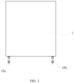
- the surge protection device includes a housing 1 with at two lead-out electrodes 10a and 10b, and a voltage limiting device 2 and a thermal tripping mechanism 3 that are installed in the housing 1.
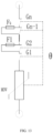
- Circuit principles of the surge protection device are shown in FIG. 1 and FIG. 2 .
- FIG. 1 shows a circuit principle before thermal tripping.
- FIG. 2 shows a circuit principle after thermal tripping.
- the voltage limiting device 2 includes a voltage limiter 20, a first electrode 21, a second electrode 22, and an insulating cover 23.
- the voltage limiter 20 may be a voltage limiting element such as a voltage-dependent resistor or a transient voltage suppressor.
- the voltage limiting device 20 is a voltage-dependent resistor. Both ends of the voltage limiter 20 are connected to the first electrode 21 and the second electrode 22 respectively, and the voltage limiter 20, the first electrode 21, and the second electrode 22 are all installed in the insulating cover 23.
- a gap in the insulating cover 23 can also be filled with insulating colloids such as epoxy resin and silica gel.
- the thermal tripping mechanism 3 includes a fixed assembly, a movable assembly, an energy storage member 32, and a thermal trigger device 33.
- the fixed assembly includes a fixed bracket 300 and n (n ⁇ 2) fixed electrodes 301 fixed on the fixed bracket 300, and the fixed electrodes 301 are disconnected from each other and in a non-conductive state.
- the movable assembly includes a movable bracket 310 and n+1 movable electrodes 311 fixed on the movable bracket 310.
- a gap (Gn) is formed between two adjacent movable electrodes 311, in other words, a gap (G1) is formed between a 1 st movable electrode 311 and a 2 nd movable electrode 311, a gap (G2) is formed between the 2 nd movable electrode 311 and a 3 rd movable electrode 311, and a gap (G3) is formed between the 3 rd movable electrode 311 and a 4 th movable electrode 311, ..., and a gap (Gn) is formed between an n th movable electrode 311 and an (n+1) th movable electrode 311.
- an interval between gaps (Gn) shall not be less than 0.1 mm to avoid arc restriking, and is preferably 0.6 mm to 1.5 mm, to avoid arc restriking and present too large space from being occupied.
- the energy storage member 32 acts on the movable bracket 310, such that the movable bracket 310 can generate a relative displacement relative to the fixed bracket 300.
- the thermal tripping mechanism 3 has a first state in which the movable bracket 310 is not displaced relative to the fixed bracket 300 and a second state after a displacement.
- each fixed electrode 301 is in contact with two adjacent movable electrodes 311 corresponding to each fixed electrode 301 to allow all the fixed electrodes 301 to be in a conducting state.
- a first fixed electrode 301 is in contact with the 1 st movable electrode 311 and the 2 nd movable electrode 311
- a 2 nd fixed electrode 301 is in contact with the 2 nd movable electrode 311 and the 3 rd movable electrode 311
- a 3 rd fixed electrode 301 is in contact with the 3 rd movable electrode 311 and the 4 th movable electrode 311, ...
- an n th fixed electrode 301 is in contact with the n th movable electrode 311 and the (n+1) th movable electrode 311.
- the gap formed between the two adjacent movable electrodes 311 is exactly located at a position at which two adjacent fixed electrodes 301 corresponding to the two adjacent movable electrodes are disconnected from each other, such that the fixed electrode 301 is only in contact with one movable electrode 311.
- the fixed electrodes 301 are disconnected from each other and in a non-conducting state.
- the first fixed electrode 301 is only in contact with the 1 st movable electrode 311
- the 2 nd fixed electrode 301 is only in contact with the 2 nd movable electrode 311, ...
- the n th fixed electrode 301 is only in contact with the n th movable electrode 311.
- the first fixed electrode 301 is only in contact with the 2 nd movable electrode 311, the 2 nd fixed electrode 301 is only in contact with the 3 rd movable electrode 311, ..., and the n th fixed electrode 301 is only in contact with the (n+1) th movable electrode 311.
- the thermal trigger device 33 includes a metal trigger sheet 330.
- One end of the metal trigger sheet 330 is fixed on the fixed bracket 300, and the other end of the metal trigger sheet 330 is fixed on the second electrode 22 of the voltage limiting device 2 through welding through a fusible alloy.
- the fusible alloy mentioned herein usually refers to metal with a melting point below 300°C and its alloy.
- the fusible alloy is composed of low-melting point metal elements such as Bi, Sn, Pb, and In. When these metal elements are combined in different proportions, alloys with different melting points (binary, ternary or quaternary alloys) can be obtained.
- the metal trigger sheet 330 may be made of brass, bronze, white copper, or other materials.
- the metal trigger sheet 330 and the second electrode 22 are directly fixed through welding, which is more conducive to transferring heat of the voltage limiting device 2 to a welding point, so as to melt the fusible alloy and realize tripping, thereby realizing more timely thermal tripping of the metal trigger sheet 330.
- the movable bracket 310 When the metal trigger sheet 330 and the second electrode 22 of the voltage limiting device 2 are fixed through welding, the movable bracket 310 is not displaced relative to the fixed bracket 300, and the thermal tripping mechanism 3 is in the first state. In this case, the thermal tripping mechanism 3 is in the conducting state.
- the thermal tripping mechanism 3 When the heat generated by the voltage limiting device 2 is greater than a specified value, the welding point of the fusible alloy for fixing the metal trigger sheet 330 and the second electrode 22 is melted. Under the acting force of the energy storage member 32, the movable bracket 310 is displaced relative to the fixed bracket 300, the gap is effectively disconnected, and a main circuit is disconnected, thereby protecting against thermal tripping.
- the fusible alloy as a welding point of a thermal trigger medium in thermal tripping is not connected to a circuit, so a thermal protection device does not trip by mistake or in advance when a surge current flows through the thermal protection device.
- a plurality of ( ⁇ 2) gaps connected in series have a higher arc voltage drop than a single gap, which can limit an arc current.
- An enough number of the gaps can limit the current within a safe range. This avoids a risk of misoperation caused by a thermal effect and an electrodynamic effect when a lightning current passes through a thermal trigger medium of a thermal release device of a conventional surge protection device.
- the fixed assembly and the movable assembly may adopt a solution in which the movable assembly rotates relative to the fixed assembly to realize the displacement, as shown in the figure, but are not limited thereto.
- a solution in which the movable assembly moves linearly relative to the fixed assembly to realize the displacement may be adopted
- the energy storage member 32 is a torsional spring.
- the energy storage member 32 is a compressed spring.
- the solution in which the displacement is generated through rotation is adopted.
- the solution in which the displacement is generated through rotation can make a structure of the thermal tripping mechanism 3 more compact and a required volume smaller.
- the movable bracket 310 and the fixed bracket 300 constitute a structure similar to a stator and a rotor.
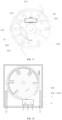
- the fixed bracket 300 is provided with a roughly cylindrical cavity for placing the movable bracket 310, and a rotating shaft 302 located in a center of the cavity.
- the movable bracket 310 is pivoted on the fixed bracket 300 through the rotating shaft 302, and has a roughly cylindrical outer peripheral wall.
- the n fixed electrodes 301 on the fixed bracket 300 are sequentially fixed on an inner peripheral wall of the cavity, and the n movable electrodes 311 on the movable bracket 310 are sequentially fixed on the outer peripheral wall of the movable bracket 310.
- a center of the torsional spring as the energy storage member 32 is sleeved on the rotating shaft 302.
- one foot of the torsional spring is fixed on a detent of the fixed bracket 300 and the other foot is fixed on a detent of the movable bracket.
- the twisting force of the fixed torsional spring can push the movable assembly to rotate towards a direction through the rotating shaft 302 as a center of a circle (in this embodiment, a clockwise direction is taken as an example).
- the metal trigger sheet 330 in this embodiment has a roughly L-shaped structure. One end of the metal trigger sheet 330 is fixed on the movable bracket 310, and the other end extends to the outside of the movable bracket 310 and is fixed with the second electrode 22 through welding, to limit rotation of the movable assembly.
- the movable bracket 310 is provided with a limit clamping point that has a matching setting on the fixed bracket 300, and the limit clamping point can limit a rotation angle and direction of the movable assembly relative to the fixed assembly.
- the limit clamping point in this embodiment is disposed on a protrusion portion 312 on the outer peripheral wall of the movable bracket 310, and the inner wall of the cavity of the fixed bracket 300 is provided with an avoidance slot 303 that matches the protrusion portion 312 and corresponds to the rotation angle of the movable assembly.
- the protrusion portion 312 can only move in the avoidance slot 303.
- the protrusion portion 312 can limit the rotation angle of the movable bracket 310, such that the gap on the movable bracket 310 is exactly located at the position at which the two adjacent fixed electrodes 301 corresponding to the two adjacent movable electrodes are disconnected from each other, to ensure the safety of a circuit port.
- each electrode in this embodiment is preferably made of copper or a copper alloy, and a copper electrode is used as an example to describe the electrodes in this embodiment.
- the housing 1, the insulating cover 23, the fixed bracket 300, and the movable bracket 310 are preferably made of materials with high flame resistance and high temperature resistance, and more preferably, are made of special engineering plastics such as polyphenylene sulfide (PPS), polyimide (PI), polyetheretherketone (PEEK), and polysulfone (PSF). In this way, they not only have high flame resistance and high temperature resistance, but also have advantages of high strength, earthquake resistance, and drop resistance, to ensure safety and durability of the surge protector.
- PPS polyphenylene sulfide
- PI polyimide
- PEEK polyetheretherketone
- PSF polysulfone
- the first electrode 21 and the second electrode 22 of the voltage limiting device 2 are respectively provided with a first electrode lead-out portion 210 and a second electrode lead-out portion 220 that extend to the outside of the insulating cover 23.
- the first fixed electrode 301 and the n th fixed electrode 301 on the fixed assembly are provided with fixed electrode lead-out portions 301a and 301b respectively.
- the first electrode lead-out portion 210 is disposed tightly adjacent to one lead-out electrode 10a
- the second electrode lead-out portion 220 is disposed tightly adjacent to the fixed electrode lead-out portion 301a
- the fixed electrode lead-out portion 301b is disposed tightly adjacent to another lead-out electrode 10b, so as to facilitate electrical connection between these electrodes.
- Such a setting herein means that two elements abut one another or two elements with a small spacing can be directly fixed through welding.
- This embodiment also provides a surge protection device with a high breaking capacity.
- the surge protection device has a basically same structure as the surge protection device in Embodiment 1, and a difference between the two surge protection devices is that their application protection modes are different, as shown in FIG. 13 to FIG. 15 .
- the surge protection device in this embodiment is provided with a current fuse connected in parallel to each of k gaps of n (n ⁇ 2) gaps connected in series, where k ⁇ n. Circuit principles of the surge protection device are shown in FIG. 13 to FIG. 15 .
- FIG 13 shows a circuit principle before thermal tripping.
- FIG. 14 shows a circuit principle during thermal tripping.
- FIG. 15 shows a circuit principle after thermal tripping.
- the voltage limiter 20 in this embodiment is the same as that in Embodiment 1, and description is also provided through an example in which the voltage limiter 20 is a voltage-dependent resistor.
- the surge protection device uses the current fuse for current shunting, to extinguish the arc at the gap first. Then fusing of the fuse is a breaking process.
- the fuse has a higher current breaking capacity than a single gap, thereby further improving a breaking capacity of the surge protection device.
- k current fuses Fk are disposed in parallel to the movable electrodes 311 on both sides of each even-numbered gap (G2, G4, G6).
- the movable bracket 310 is provided with a plurality of fixing slots 314 for placing the current fuse.
- the current fuse Fk can be placed in a corresponding fixing slot 314, and each fixing slot 314 is connected to two opposite latching slots 315.
- Two pins of the current fuse fixed in the fixing slot 314 are in conductive contact with fixed electrodes on both sides of a corresponding gap through the two latching slots 315, so as to facilitate fixing of the current fuse and conduction with the corresponding fixed electrode.
- This embodiment also provides a surge protection device with a high breaking capacity.
- the surge protection device has a basically same structure as the surge protection device in Embodiment 1 or Embodiment 2, and a difference among the surge protection devices is that the surge protection device in this embodiment further has a remote signaling switch or a window in linkage with the movable assembly, to generate a failure signal
- FIG. 18 is a schematic diagram of adding a remote signaling switch to the surge protection device in Embodiment 1
- FIG. 19 is a schematic diagram of adding a remote signaling switch to the surge protection device in Embodiment 2.
- the remote signaling trigger portion 316 is the protrusion portion 312 in Embodiment 1, in other words, the protrusion portion 312 is used not only as a component to limit the rotation angle of the movable bracket 310, but also as the remote signaling trigger portion 316 to trigger the remote signaling switch 4. In this way, there is no need to add a corresponding structure or functional part on the movable bracket 310, making a structure of the movable bracket 310 simpler and more compact.
- This embodiment also provides a surge protection device with a high breaking capacity.
- the surge protection device has a basically same structure as the surge protection device in Embodiment 1 or Embodiment 2, and a difference among the surge protection devices is that the movable electrode 311 in Embodiment 1 or Embodiment 2 is made of copper or a copper alloy, and the movable electrode 311 in this embodiment is made of graphite, as shown in FIG. 20 .
- the movable electrode 311 of a corresponding material may be selected based on a protection mode.
Landscapes
- Engineering & Computer Science (AREA)
- Microelectronics & Electronic Packaging (AREA)
- Power Engineering (AREA)
- Physics & Mathematics (AREA)
- Electromagnetism (AREA)
- Chemical & Material Sciences (AREA)
- Combustion & Propulsion (AREA)
- Breakers (AREA)
- Emergency Protection Circuit Devices (AREA)
- Fuses (AREA)
Claims (11)
- Überspannungsschutzvorrichtung mit einer hohen Schutzkapazität, umfassend ein Gehäuse (1) mit wenigstens zwei herausführenden Elektroden (10a, 10b), eine Spannungsbegrenzungsvorrichtung (2) und einen Wärmeauslösungsmechanismus (3), wobei die Spannungsbegrenzungsvorrichtung (2) und der Wärmeauslösungsmechanismus (3) in dem Gehäuse (1) installiert sind, dadurch gekennzeichnet, dassdie Spannungsbegrenzungsvorrichtung (2) einen Spannungsbegrenzer (20), eine erste Elektrode (21) und eine zweite Elektrode (22) umfasst, wobei der Spannungsbegrenzer (20), die erste Elektrode (21) und die zweite Elektrode (22) in einer isolierenden Abdeckung (23) angeordnet und installiert sind;wobei der Wärmeauslösungsmechanismus (3) eine fixierte Baugruppe, eine bewegbare Baugruppe und eine Wärmeauslösevorrichtung (33) umfasst, wobeidie fixierte Baugruppe und die bewegbare Baugruppe eine Vielzahl von in Reihe geschalteten Verlagerungsschaltern bilden;die Wärmeauslösevorrichtung (33) in Verbindung mit der bewegbare Baugruppe angeordnet ist und die Wärmeauslösevorrichtung (33) ein Auslöseblech (330), eine schmelzbare Legierung und ein Energiespeicherelement (32) umfasst;wobei ein erstes Ende des Auslöseblechs (330) an der bewegbaren Baugruppe fixiert ist und ein zweites Ende des Auslöseblechs (330) durch Schweißen mittels der schmelzbaren Legierung an der zweiten Elektrode (22) fixiert ist, wobei eine Verlagerung der bewegbaren Baugruppe relativ zu der fixierten Baugruppe eingeschränkt wird, und wobei das Energiespeicherelement (32) potenzielle Energie akkumuliert, um die bewegbare Baugruppe relativ zu der fixierten Baugruppe zu verlagern; undwobei die erste Elektrode (21) elektrisch mit einer herausführenden Elektrode der wenigstens zwei herausführenden Elektroden (10a, 10b) verbunden ist und eines der beiden Enden der Vielzahl von in Reihe geschalteten Verlagerungsschaltern elektrisch mit der zweiten Elektrode (22) und das andere mit einer anderen herausführenden Elektrode der wenigstens zwei herausführenden Elektroden (10a, 10b) verbunden ist.
- Überspannungsschutzvorrichtung nach Anspruch 1, dadurch gekennzeichnet, dassdie fixierte Baugruppe eine fixierte Halterung (300) und n fixierte Elektroden (301) umfasst, die der Reihe nach an der fixierten Halterung (300) sind, wobei n≥2, und wobei die n fixierten Elektroden (301) voneinander getrennt sind;die bewegbare Baugruppe eine bewegbare Halterung (310) und n+1 bewegbare Elektroden (311) umfasst, die der Reihe nach an der bewegbaren Halterung (310) fixiert sind;ein Spalt (Gn) zwischen zwei benachbarten bewegbaren Elektroden (311) gebildet ist;die bewegbare Halterung (310) einen ersten Zustand und einen zweiten Zustand aufweist, wobei die bewegbare Halterung (310) im ersten Zustand keine Verlagerung relativ zu der fixierten Halterung (300) aufweist und die bewegbare Halterung (310) im zweiten Zustand eine Verlagerung relativ zu der fixierten Halterung (300) aufweist;wobei im ersten Zustand jede fixierte Elektrode (301) der n fixierten Elektroden (301) mit zwei benachbarten bewegbaren Elektroden (311) in Kontakt steht, die den einzelnen fixierten Elektroden (301) entsprechen, um zu ermöglichen, dass sich die n fixierten Elektroden (301) in einem leitenden Zustand befinden; undwobei sich der zwischen den zwei benachbarten bewegbaren Elektroden (311) gebildete Spalt (Gn) im zweiten Zustand genau an einer Position befindet, wobei zwei benachbarte fixierte Elektroden (301), die den zwei benachbarten bewegbaren Elektroden (311) entsprechen, an dieser Position voneinander getrennt sind, wobei sich die n fixierten Elektroden (301) voneinander getrennt und in einem nichtleitenden Zustand befinden.
- Überspannungsschutzvorrichtung nach Anspruch 2, dadurch gekennzeichnet, dass
an der bewegbaren Halterung (310) und an der fixierten Halterung (300) miteinander übereinstimmende Einschränkungsstrukturen angeordnet sind und die Einschränkungsstrukturen eine Verlagerungsstrecke oder einen Winkel der bewegbaren Halterung (310) relativ zu der fixierten Halterung (300) einschränken. - Überspannungsschutzvorrichtung nach Anspruch 3, dadurch gekennzeichnet, dass die Einschränkungsstrukturen ein Vorsprungabschnitt (312), der an der bewegbaren Halterung (310) angeordnet ist, und ein Ausweichschlitz (303) sind, der an der fixierten Halterung (300) angeordnet ist.
- Überspannungsschutzvorrichtung nach Anspruch 2, dadurch gekennzeichnet, dass ein Intervall zwischen Spalten (Gn) größer als oder gleich 0,1 mm ist.
- Überspannungsschutzvorrichtung nach Anspruch 2, dadurch gekennzeichnet, dassdie fixierte Halterung (300) mit einem ungefähr zylinderförmigen Hohlraum versehen ist und eine Mitte des ungefähr zylinderförmigen Hohlraums mit einem Drehschaft (302) versehen ist;die bewegbare Halterung (310) durch den Drehschaft (302) an der fixierten Halterung (300) geschwenkt wird und die bewegbare Halterung (310) eine Außenumfangswand aufweist, die einer Innenwand des ungefähr zylinderförmigen Hohlraums entspricht; unddie n fixierten Elektroden (301) an der Innenwand des ungefähr zylinderförmigen Hohlraums fixiert sind und die n+1 bewegbaren Elektroden (311) an der Außenumfangswand der bewegbaren Halterung (310) fixiert sind.
- Überspannungsschutzvorrichtung nach Anspruch 6, dadurch gekennzeichnet, dass die erste Elektrode (21) und die zweite Elektrode (22) der Spannungsbegrenzungsvorrichtung (2) jeweils mit einem herausführenden Abschnitt (210) der ersten Elektrode und einem herausführenden Abschnitt (220) der zweiten Elektrode versehen sind, wobei sich der herausführende Abschnitt (210) der ersten Elektrode und der herausführende Abschnitt (220) der zweiten Elektrode aus der isolierenden Abdeckung (23) heraus erstrecken;eine erste fixierte Elektrode (301) und eine n-te fixierte Elektrode (301) an der fixierten Baugruppe jeweils mit einem herausführenden Abschnitt der fixierten Elektrode versehen sind;wobei der herausführende Abschnitt (210) der ersten Elektrode eng benachbart zu einer herausführenden Elektrode (10a) angeordnet ist, der herausführende Abschnitt (220) der zweiten Elektrode eng benachbart zu einem herausführenden Abschnitt (301a) der fixierten Elektrode angeordnet ist und ein anderer herausführender Abschnitt (301b) der fixierten Elektrode eng benachbart zu einer anderen herausführenden Elektrode (10b) angeordnet ist.
- Überspannungsschutzvorrichtung nach Anspruch 2, dadurch gekennzeichnet, dass
die Überspannungsschutzvorrichtung mit einer Stromsicherung versehen ist, wobei die Stromsicherung mit jedem von k Spalten der n in Reihe geschalteten Spalten (Gn) parallel geschaltet ist, wobei k≤n. - Überspannungsschutzvorrichtung nach Anspruch 8, dadurch gekennzeichnet, dass
bewegbare Elektroden (311) auf beiden Seiten jedes geradzahligen Spalts (G2, G4, G6...) mit der Stromsicherung parallel geschaltet sind. - Überspannungsschutzvorrichtung nach Anspruch 8, dadurch gekennzeichnet, dassdie bewegbare Halterung (310) mit einer Vielzahl von Fixierungsschlitzen (314) zum Anordnen der Stromsicherung versehen ist; und jeder Fixierungsschlitz (314) der Vielzahl von Fixierungsschlitzen (314) mit zwei gegenüberliegenden Arretierungsschlitzen (315) verbunden ist, undzwei Stifte der Stromsicherung, die in jedem Fixierungsschlitz (314) fixiert sind, durch die zwei gegenüberliegenden Arretierungsschlitze (315) in leitendem Kontakt mit fixierten Elektroden (301) auf beiden Seiten eines entsprechenden Spalts stehen.
- Überspannungsschutzvorrichtung nach Anspruch 2, ferner umfassend einen Fernsignalisierungsschalter (4) oder ein Fenster, dadurch gekennzeichnet, dass der Fernsignalisierungsschalter (4) oder das mit der bewegbaren Baugruppe in Verbindung steht.
Applications Claiming Priority (2)
| Application Number | Priority Date | Filing Date | Title |
|---|---|---|---|
| CN201910932326.0A CN110492463B (zh) | 2019-09-29 | 2019-09-29 | 一种具有高分断能力的电涌保护装置 |
| PCT/CN2020/100457 WO2021057163A1 (zh) | 2019-09-29 | 2020-07-06 | 一种具有高分断能力的电涌保护装置 |
Publications (3)
| Publication Number | Publication Date |
|---|---|
| EP3972068A1 EP3972068A1 (de) | 2022-03-23 |
| EP3972068A4 EP3972068A4 (de) | 2022-09-14 |
| EP3972068B1 true EP3972068B1 (de) | 2023-10-04 |
Family
ID=68544294
Family Applications (1)
| Application Number | Title | Priority Date | Filing Date |
|---|---|---|---|
| EP20869674.0A Active EP3972068B1 (de) | 2019-09-29 | 2020-07-06 | Überspannungsschutzvorrichtung mit hohem ausschaltvermögen |
Country Status (4)
| Country | Link |
|---|---|
| US (1) | US11742656B2 (de) |
| EP (1) | EP3972068B1 (de) |
| CN (1) | CN110492463B (de) |
| WO (1) | WO2021057163A1 (de) |
Families Citing this family (4)
| Publication number | Priority date | Publication date | Assignee | Title |
|---|---|---|---|---|
| CN110492463B (zh) * | 2019-09-29 | 2024-11-08 | 厦门赛尔特电子股份有限公司 | 一种具有高分断能力的电涌保护装置 |
| US11862967B2 (en) * | 2021-09-13 | 2024-01-02 | Raycap, S.A. | Surge protective device assembly modules |
| CN116052971A (zh) * | 2023-01-10 | 2023-05-02 | 深圳市辰驹电子科技有限公司 | 一种热脱扣保护压敏电阻器 |
| CN121075876A (zh) * | 2024-12-31 | 2025-12-05 | 成都标定科技有限责任公司 | 一种刀片型1u浪涌保护器 |
Family Cites Families (17)
| Publication number | Priority date | Publication date | Assignee | Title |
|---|---|---|---|---|
| US5321574A (en) | 1992-01-17 | 1994-06-14 | Siemens Energy & Automation, Inc. | Circuit breaker/surge arrestor package in which the arrestor uses an MOV that is thermally de-coupled from the breaker's thermal trip circuit |
| US6040971A (en) * | 1998-06-08 | 2000-03-21 | Martenson; Kenneth R. | Circuit protection device |
| DE102009030629A1 (de) * | 2009-06-25 | 2010-12-30 | Phoenix Contact Gmbh & Co. Kg | Überspannungsschutzelement |
| CN101692393B (zh) * | 2009-09-11 | 2012-09-05 | 辽宁金立电力电器有限公司 | 有载调节20kV及以下电网中调容变压器的开关 |
| FR2958787B1 (fr) * | 2010-04-09 | 2012-05-11 | Abb France | Dispositif de protection contre les surtensions a deconnecteurs thermiques dedoubles |
| DE102011018556A1 (de) * | 2011-02-18 | 2012-08-23 | Dehn + Söhne Gmbh + Co. Kg | Überspannungsschutzeinrichtung, umfassend mindestens einen Überspannungsableiter |
| CN103296670A (zh) * | 2012-03-02 | 2013-09-11 | 广东电网公司清远供电局 | 一种电力系统中用的直流电源防雷器 |
| DE102013019391B4 (de) * | 2013-04-11 | 2022-04-28 | Dehn Se | Anordnung zum Überlastschutz von Überspannungsschutzgeräten |
| CN203967740U (zh) * | 2014-02-24 | 2014-11-26 | 贵阳高新益舸电子有限公司 | 可确保热脱离机构动作的新型浪涌保护器 |
| DE202014002496U1 (de) * | 2014-03-20 | 2014-04-17 | Dehn + Söhne Gmbh + Co. Kg | Überspannungsschutzeinrichtung, umfassend mindestens einen Überspannungsableiter und eine dem Überspannungsableiter parallel geschaltete, thermisch auslösbare, federvorgespannte Kurzschliessschalteinrichtung |
| CN203839326U (zh) * | 2014-05-07 | 2014-09-17 | 厦门赛尔特电子有限公司 | 一种高压直流温度保险丝 |
| CN107424881A (zh) * | 2017-09-18 | 2017-12-01 | 广西新全通电子技术有限公司 | 一种快速分断的电涌保护器及其应用 |
| CN107516885A (zh) * | 2017-09-18 | 2017-12-26 | 广西新全通电子技术有限公司 | 一种双分离的防弧型电涌保护装置及其应用 |
| CN208174263U (zh) * | 2018-04-23 | 2018-11-30 | 厦门赛尔特电子有限公司 | 一种新型的热保护型压敏电阻 |
| CN209434871U (zh) * | 2019-01-29 | 2019-09-24 | 厦门赛尔特电子有限公司 | 一种浪涌保护器 |
| CN210490462U (zh) * | 2019-09-29 | 2020-05-08 | 厦门赛尔特电子有限公司 | 一种具有高分断能力的电涌保护装置 |
| CN110492463B (zh) * | 2019-09-29 | 2024-11-08 | 厦门赛尔特电子股份有限公司 | 一种具有高分断能力的电涌保护装置 |
-
2019
- 2019-09-29 CN CN201910932326.0A patent/CN110492463B/zh active Active
-
2020
- 2020-07-06 WO PCT/CN2020/100457 patent/WO2021057163A1/zh not_active Ceased
- 2020-07-06 EP EP20869674.0A patent/EP3972068B1/de active Active
- 2020-07-06 US US17/623,856 patent/US11742656B2/en active Active
Also Published As
| Publication number | Publication date |
|---|---|
| CN110492463B (zh) | 2024-11-08 |
| US20220360071A1 (en) | 2022-11-10 |
| EP3972068A4 (de) | 2022-09-14 |
| US11742656B2 (en) | 2023-08-29 |
| WO2021057163A1 (zh) | 2021-04-01 |
| EP3972068A1 (de) | 2022-03-23 |
| CN110492463A (zh) | 2019-11-22 |
Similar Documents
| Publication | Publication Date | Title |
|---|---|---|
| US11742656B2 (en) | Surge protection device with high breaking capacity | |
| CN103703534B (zh) | 具有转盘且具有用于延长过压元件的寿命的额外的电子组装的冗余过压电路断路器 | |
| US8816812B2 (en) | Varistor fuse element | |
| AU679288B2 (en) | Improved current limiting fuse and dropout fuseholder | |
| US20150103462A1 (en) | Overvoltage protection device | |
| CN1710770A (zh) | 电压浪涌保护装置 | |
| EP2919254A1 (de) | Überspannungsschutzvorrichtung mit schutzfunktion gegen kurzschlussstrom | |
| JP5959447B2 (ja) | サージ防護装置 | |
| EP3776604B1 (de) | Dreiphasige überspannungsschutzvorrichtung | |
| CN106716591A (zh) | 一种用于被保护装置的熔断器 | |
| JP5959007B2 (ja) | サージ防護装置 | |
| US7633737B2 (en) | Liquid immersed surge arrester | |
| CN103931064B (zh) | 用于断开两个连接点之间的电连接的方法和电路装置 | |
| CN210490462U (zh) | 一种具有高分断能力的电涌保护装置 | |
| CN206163439U (zh) | 一种新型的电涌保护装置 | |
| US12494632B2 (en) | Chargeless interrupter device for surge arrester | |
| CN106887822B (zh) | 一种过压保护装置 | |
| CN117080028B (zh) | 具有灭弧功能的电涌抑制装置 | |
| EP4099358B1 (de) | Überstromschutzeinrichtung, insbesondere zum schutz von überspannungsableitern |
Legal Events
| Date | Code | Title | Description |
|---|---|---|---|
| STAA | Information on the status of an ep patent application or granted ep patent |
Free format text: STATUS: THE INTERNATIONAL PUBLICATION HAS BEEN MADE |
|
| PUAI | Public reference made under article 153(3) epc to a published international application that has entered the european phase |
Free format text: ORIGINAL CODE: 0009012 |
|
| STAA | Information on the status of an ep patent application or granted ep patent |
Free format text: STATUS: REQUEST FOR EXAMINATION WAS MADE |
|
| 17P | Request for examination filed |
Effective date: 20211217 |
|
| AK | Designated contracting states |
Kind code of ref document: A1 Designated state(s): AL AT BE BG CH CY CZ DE DK EE ES FI FR GB GR HR HU IE IS IT LI LT LU LV MC MK MT NL NO PL PT RO RS SE SI SK SM TR |
|
| A4 | Supplementary search report drawn up and despatched |
Effective date: 20220816 |
|
| RIC1 | Information provided on ipc code assigned before grant |
Ipc: H02H 7/00 20060101ALI20220810BHEP Ipc: H02H 5/04 20060101ALI20220810BHEP Ipc: H01C 7/12 20060101ALI20220810BHEP Ipc: H01T 1/14 20060101ALI20220810BHEP Ipc: H01H 37/76 20060101ALI20220810BHEP Ipc: H02H 9/04 20060101AFI20220810BHEP |
|
| DAV | Request for validation of the european patent (deleted) | ||
| DAX | Request for extension of the european patent (deleted) | ||
| GRAP | Despatch of communication of intention to grant a patent |
Free format text: ORIGINAL CODE: EPIDOSNIGR1 |
|
| STAA | Information on the status of an ep patent application or granted ep patent |
Free format text: STATUS: GRANT OF PATENT IS INTENDED |
|
| RIC1 | Information provided on ipc code assigned before grant |
Ipc: H02H 7/00 20060101ALI20230516BHEP Ipc: H02H 5/04 20060101ALI20230516BHEP Ipc: H01C 7/12 20060101ALI20230516BHEP Ipc: H01T 1/14 20060101ALI20230516BHEP Ipc: H01H 37/76 20060101ALI20230516BHEP Ipc: H02H 9/04 20060101AFI20230516BHEP |
|
| INTG | Intention to grant announced |
Effective date: 20230606 |
|
| GRAS | Grant fee paid |
Free format text: ORIGINAL CODE: EPIDOSNIGR3 |
|
| GRAA | (expected) grant |
Free format text: ORIGINAL CODE: 0009210 |
|
| STAA | Information on the status of an ep patent application or granted ep patent |
Free format text: STATUS: THE PATENT HAS BEEN GRANTED |
|
| AK | Designated contracting states |
Kind code of ref document: B1 Designated state(s): AL AT BE BG CH CY CZ DE DK EE ES FI FR GB GR HR HU IE IS IT LI LT LU LV MC MK MT NL NO PL PT RO RS SE SI SK SM TR |
|
| REG | Reference to a national code |
Ref country code: GB Ref legal event code: FG4D |
|
| REG | Reference to a national code |
Ref country code: CH Ref legal event code: EP |
|
| P01 | Opt-out of the competence of the unified patent court (upc) registered |
Effective date: 20230919 |
|
| REG | Reference to a national code |
Ref country code: IE Ref legal event code: FG4D |
|
| REG | Reference to a national code |
Ref country code: DE Ref legal event code: R096 Ref document number: 602020018836 Country of ref document: DE |
|
| REG | Reference to a national code |
Ref country code: LT Ref legal event code: MG9D |
|
| REG | Reference to a national code |
Ref country code: NL Ref legal event code: MP Effective date: 20231004 |
|
| REG | Reference to a national code |
Ref country code: AT Ref legal event code: MK05 Ref document number: 1618749 Country of ref document: AT Kind code of ref document: T Effective date: 20231004 |
|
| PG25 | Lapsed in a contracting state [announced via postgrant information from national office to epo] |
Ref country code: NL Free format text: LAPSE BECAUSE OF FAILURE TO SUBMIT A TRANSLATION OF THE DESCRIPTION OR TO PAY THE FEE WITHIN THE PRESCRIBED TIME-LIMIT Effective date: 20231004 |
|
| PG25 | Lapsed in a contracting state [announced via postgrant information from national office to epo] |
Ref country code: GR Free format text: LAPSE BECAUSE OF FAILURE TO SUBMIT A TRANSLATION OF THE DESCRIPTION OR TO PAY THE FEE WITHIN THE PRESCRIBED TIME-LIMIT Effective date: 20240105 |
|
| PG25 | Lapsed in a contracting state [announced via postgrant information from national office to epo] |
Ref country code: IS Free format text: LAPSE BECAUSE OF FAILURE TO SUBMIT A TRANSLATION OF THE DESCRIPTION OR TO PAY THE FEE WITHIN THE PRESCRIBED TIME-LIMIT Effective date: 20240204 |
|
| PG25 | Lapsed in a contracting state [announced via postgrant information from national office to epo] |
Ref country code: LT Free format text: LAPSE BECAUSE OF FAILURE TO SUBMIT A TRANSLATION OF THE DESCRIPTION OR TO PAY THE FEE WITHIN THE PRESCRIBED TIME-LIMIT Effective date: 20231004 |
|
| PG25 | Lapsed in a contracting state [announced via postgrant information from national office to epo] |
Ref country code: AT Free format text: LAPSE BECAUSE OF FAILURE TO SUBMIT A TRANSLATION OF THE DESCRIPTION OR TO PAY THE FEE WITHIN THE PRESCRIBED TIME-LIMIT Effective date: 20231004 |
|
| PG25 | Lapsed in a contracting state [announced via postgrant information from national office to epo] |
Ref country code: ES Free format text: LAPSE BECAUSE OF FAILURE TO SUBMIT A TRANSLATION OF THE DESCRIPTION OR TO PAY THE FEE WITHIN THE PRESCRIBED TIME-LIMIT Effective date: 20231004 |
|
| PG25 | Lapsed in a contracting state [announced via postgrant information from national office to epo] |
Ref country code: LT Free format text: LAPSE BECAUSE OF FAILURE TO SUBMIT A TRANSLATION OF THE DESCRIPTION OR TO PAY THE FEE WITHIN THE PRESCRIBED TIME-LIMIT Effective date: 20231004 Ref country code: IS Free format text: LAPSE BECAUSE OF FAILURE TO SUBMIT A TRANSLATION OF THE DESCRIPTION OR TO PAY THE FEE WITHIN THE PRESCRIBED TIME-LIMIT Effective date: 20240204 Ref country code: GR Free format text: LAPSE BECAUSE OF FAILURE TO SUBMIT A TRANSLATION OF THE DESCRIPTION OR TO PAY THE FEE WITHIN THE PRESCRIBED TIME-LIMIT Effective date: 20240105 Ref country code: ES Free format text: LAPSE BECAUSE OF FAILURE TO SUBMIT A TRANSLATION OF THE DESCRIPTION OR TO PAY THE FEE WITHIN THE PRESCRIBED TIME-LIMIT Effective date: 20231004 Ref country code: BG Free format text: LAPSE BECAUSE OF FAILURE TO SUBMIT A TRANSLATION OF THE DESCRIPTION OR TO PAY THE FEE WITHIN THE PRESCRIBED TIME-LIMIT Effective date: 20240104 Ref country code: AT Free format text: LAPSE BECAUSE OF FAILURE TO SUBMIT A TRANSLATION OF THE DESCRIPTION OR TO PAY THE FEE WITHIN THE PRESCRIBED TIME-LIMIT Effective date: 20231004 Ref country code: PT Free format text: LAPSE BECAUSE OF FAILURE TO SUBMIT A TRANSLATION OF THE DESCRIPTION OR TO PAY THE FEE WITHIN THE PRESCRIBED TIME-LIMIT Effective date: 20240205 |
|
| PG25 | Lapsed in a contracting state [announced via postgrant information from national office to epo] |
Ref country code: SE Free format text: LAPSE BECAUSE OF FAILURE TO SUBMIT A TRANSLATION OF THE DESCRIPTION OR TO PAY THE FEE WITHIN THE PRESCRIBED TIME-LIMIT Effective date: 20231004 Ref country code: RS Free format text: LAPSE BECAUSE OF FAILURE TO SUBMIT A TRANSLATION OF THE DESCRIPTION OR TO PAY THE FEE WITHIN THE PRESCRIBED TIME-LIMIT Effective date: 20231004 Ref country code: PL Free format text: LAPSE BECAUSE OF FAILURE TO SUBMIT A TRANSLATION OF THE DESCRIPTION OR TO PAY THE FEE WITHIN THE PRESCRIBED TIME-LIMIT Effective date: 20231004 Ref country code: NO Free format text: LAPSE BECAUSE OF FAILURE TO SUBMIT A TRANSLATION OF THE DESCRIPTION OR TO PAY THE FEE WITHIN THE PRESCRIBED TIME-LIMIT Effective date: 20240104 Ref country code: LV Free format text: LAPSE BECAUSE OF FAILURE TO SUBMIT A TRANSLATION OF THE DESCRIPTION OR TO PAY THE FEE WITHIN THE PRESCRIBED TIME-LIMIT Effective date: 20231004 Ref country code: HR Free format text: LAPSE BECAUSE OF FAILURE TO SUBMIT A TRANSLATION OF THE DESCRIPTION OR TO PAY THE FEE WITHIN THE PRESCRIBED TIME-LIMIT Effective date: 20231004 |
|
| REG | Reference to a national code |
Ref country code: DE Ref legal event code: R097 Ref document number: 602020018836 Country of ref document: DE |
|
| PG25 | Lapsed in a contracting state [announced via postgrant information from national office to epo] |
Ref country code: DK Free format text: LAPSE BECAUSE OF FAILURE TO SUBMIT A TRANSLATION OF THE DESCRIPTION OR TO PAY THE FEE WITHIN THE PRESCRIBED TIME-LIMIT Effective date: 20231004 |
|
| PG25 | Lapsed in a contracting state [announced via postgrant information from national office to epo] |
Ref country code: CZ Free format text: LAPSE BECAUSE OF FAILURE TO SUBMIT A TRANSLATION OF THE DESCRIPTION OR TO PAY THE FEE WITHIN THE PRESCRIBED TIME-LIMIT Effective date: 20231004 |
|
| PG25 | Lapsed in a contracting state [announced via postgrant information from national office to epo] |
Ref country code: SK Free format text: LAPSE BECAUSE OF FAILURE TO SUBMIT A TRANSLATION OF THE DESCRIPTION OR TO PAY THE FEE WITHIN THE PRESCRIBED TIME-LIMIT Effective date: 20231004 |
|
| PG25 | Lapsed in a contracting state [announced via postgrant information from national office to epo] |
Ref country code: SM Free format text: LAPSE BECAUSE OF FAILURE TO SUBMIT A TRANSLATION OF THE DESCRIPTION OR TO PAY THE FEE WITHIN THE PRESCRIBED TIME-LIMIT Effective date: 20231004 Ref country code: SK Free format text: LAPSE BECAUSE OF FAILURE TO SUBMIT A TRANSLATION OF THE DESCRIPTION OR TO PAY THE FEE WITHIN THE PRESCRIBED TIME-LIMIT Effective date: 20231004 Ref country code: RO Free format text: LAPSE BECAUSE OF FAILURE TO SUBMIT A TRANSLATION OF THE DESCRIPTION OR TO PAY THE FEE WITHIN THE PRESCRIBED TIME-LIMIT Effective date: 20231004 Ref country code: IT Free format text: LAPSE BECAUSE OF FAILURE TO SUBMIT A TRANSLATION OF THE DESCRIPTION OR TO PAY THE FEE WITHIN THE PRESCRIBED TIME-LIMIT Effective date: 20231004 Ref country code: EE Free format text: LAPSE BECAUSE OF FAILURE TO SUBMIT A TRANSLATION OF THE DESCRIPTION OR TO PAY THE FEE WITHIN THE PRESCRIBED TIME-LIMIT Effective date: 20231004 Ref country code: DK Free format text: LAPSE BECAUSE OF FAILURE TO SUBMIT A TRANSLATION OF THE DESCRIPTION OR TO PAY THE FEE WITHIN THE PRESCRIBED TIME-LIMIT Effective date: 20231004 Ref country code: CZ Free format text: LAPSE BECAUSE OF FAILURE TO SUBMIT A TRANSLATION OF THE DESCRIPTION OR TO PAY THE FEE WITHIN THE PRESCRIBED TIME-LIMIT Effective date: 20231004 |
|
| PLBE | No opposition filed within time limit |
Free format text: ORIGINAL CODE: 0009261 |
|
| STAA | Information on the status of an ep patent application or granted ep patent |
Free format text: STATUS: NO OPPOSITION FILED WITHIN TIME LIMIT |
|
| 26N | No opposition filed |
Effective date: 20240705 |
|
| PG25 | Lapsed in a contracting state [announced via postgrant information from national office to epo] |
Ref country code: SI Free format text: LAPSE BECAUSE OF FAILURE TO SUBMIT A TRANSLATION OF THE DESCRIPTION OR TO PAY THE FEE WITHIN THE PRESCRIBED TIME-LIMIT Effective date: 20231004 |
|
| PG25 | Lapsed in a contracting state [announced via postgrant information from national office to epo] |
Ref country code: SI Free format text: LAPSE BECAUSE OF FAILURE TO SUBMIT A TRANSLATION OF THE DESCRIPTION OR TO PAY THE FEE WITHIN THE PRESCRIBED TIME-LIMIT Effective date: 20231004 |
|
| PG25 | Lapsed in a contracting state [announced via postgrant information from national office to epo] |
Ref country code: MC Free format text: LAPSE BECAUSE OF FAILURE TO SUBMIT A TRANSLATION OF THE DESCRIPTION OR TO PAY THE FEE WITHIN THE PRESCRIBED TIME-LIMIT Effective date: 20231004 |
|
| REG | Reference to a national code |
Ref country code: CH Ref legal event code: PL |
|
| PG25 | Lapsed in a contracting state [announced via postgrant information from national office to epo] |
Ref country code: LU Free format text: LAPSE BECAUSE OF NON-PAYMENT OF DUE FEES Effective date: 20240706 |
|
| PG25 | Lapsed in a contracting state [announced via postgrant information from national office to epo] |
Ref country code: LU Free format text: LAPSE BECAUSE OF NON-PAYMENT OF DUE FEES Effective date: 20240706 |
|
| PG25 | Lapsed in a contracting state [announced via postgrant information from national office to epo] |
Ref country code: CH Free format text: LAPSE BECAUSE OF NON-PAYMENT OF DUE FEES Effective date: 20240731 Ref country code: BE Free format text: LAPSE BECAUSE OF NON-PAYMENT OF DUE FEES Effective date: 20240731 |
|
| REG | Reference to a national code |
Ref country code: BE Ref legal event code: MM Effective date: 20240731 |
|
| PGFP | Annual fee paid to national office [announced via postgrant information from national office to epo] |
Ref country code: GB Payment date: 20250626 Year of fee payment: 6 |
|
| PGFP | Annual fee paid to national office [announced via postgrant information from national office to epo] |
Ref country code: FR Payment date: 20250626 Year of fee payment: 6 |
|
| PG25 | Lapsed in a contracting state [announced via postgrant information from national office to epo] |
Ref country code: IE Free format text: LAPSE BECAUSE OF NON-PAYMENT OF DUE FEES Effective date: 20240706 |
|
| PG25 | Lapsed in a contracting state [announced via postgrant information from national office to epo] |
Ref country code: FI Free format text: LAPSE BECAUSE OF FAILURE TO SUBMIT A TRANSLATION OF THE DESCRIPTION OR TO PAY THE FEE WITHIN THE PRESCRIBED TIME-LIMIT Effective date: 20231004 |
|
| PGFP | Annual fee paid to national office [announced via postgrant information from national office to epo] |
Ref country code: DE Payment date: 20250627 Year of fee payment: 6 |
|
| PG25 | Lapsed in a contracting state [announced via postgrant information from national office to epo] |
Ref country code: CY Free format text: LAPSE BECAUSE OF FAILURE TO SUBMIT A TRANSLATION OF THE DESCRIPTION OR TO PAY THE FEE WITHIN THE PRESCRIBED TIME-LIMIT; INVALID AB INITIO Effective date: 20200706 |
|
| PG25 | Lapsed in a contracting state [announced via postgrant information from national office to epo] |
Ref country code: HU Free format text: LAPSE BECAUSE OF FAILURE TO SUBMIT A TRANSLATION OF THE DESCRIPTION OR TO PAY THE FEE WITHIN THE PRESCRIBED TIME-LIMIT; INVALID AB INITIO Effective date: 20200706 |