EP3971769B1 - Vorverarbeitungsverfahren zur verbesserung der bilderkennung - Google Patents
Vorverarbeitungsverfahren zur verbesserung der bilderkennung Download PDFInfo
- Publication number
- EP3971769B1 EP3971769B1 EP21151322.1A EP21151322A EP3971769B1 EP 3971769 B1 EP3971769 B1 EP 3971769B1 EP 21151322 A EP21151322 A EP 21151322A EP 3971769 B1 EP3971769 B1 EP 3971769B1
- Authority
- EP
- European Patent Office
- Prior art keywords
- light
- image sensor
- preprocessing
- emitting diode
- image
- Prior art date
- Legal status (The legal status is an assumption and is not a legal conclusion. Google has not performed a legal analysis and makes no representation as to the accuracy of the status listed.)
- Active
Links
Images


Classifications
-
- H—ELECTRICITY
- H04—ELECTRIC COMMUNICATION TECHNIQUE
- H04N—PICTORIAL COMMUNICATION, e.g. TELEVISION
- H04N23/00—Cameras or camera modules comprising electronic image sensors; Control thereof
- H04N23/80—Camera processing pipelines; Components thereof
- H04N23/84—Camera processing pipelines; Components thereof for processing colour signals
-
- G—PHYSICS
- G06—COMPUTING OR CALCULATING; COUNTING
- G06V—IMAGE OR VIDEO RECOGNITION OR UNDERSTANDING
- G06V10/00—Arrangements for image or video recognition or understanding
- G06V10/10—Image acquisition
- G06V10/12—Details of acquisition arrangements; Constructional details thereof
- G06V10/14—Optical characteristics of the device performing the acquisition or on the illumination arrangements
- G06V10/141—Control of illumination
-
- G—PHYSICS
- G06—COMPUTING OR CALCULATING; COUNTING
- G06V—IMAGE OR VIDEO RECOGNITION OR UNDERSTANDING
- G06V10/00—Arrangements for image or video recognition or understanding
- G06V10/10—Image acquisition
- G06V10/12—Details of acquisition arrangements; Constructional details thereof
- G06V10/14—Optical characteristics of the device performing the acquisition or on the illumination arrangements
- G06V10/147—Details of sensors, e.g. sensor lenses
-
- H—ELECTRICITY
- H04—ELECTRIC COMMUNICATION TECHNIQUE
- H04N—PICTORIAL COMMUNICATION, e.g. TELEVISION
- H04N23/00—Cameras or camera modules comprising electronic image sensors; Control thereof
- H04N23/60—Control of cameras or camera modules
- H04N23/61—Control of cameras or camera modules based on recognised objects
-
- H—ELECTRICITY
- H04—ELECTRIC COMMUNICATION TECHNIQUE
- H04N—PICTORIAL COMMUNICATION, e.g. TELEVISION
- H04N23/00—Cameras or camera modules comprising electronic image sensors; Control thereof
- H04N23/70—Circuitry for compensating brightness variation in the scene
- H04N23/74—Circuitry for compensating brightness variation in the scene by influencing the scene brightness using illuminating means
-
- H—ELECTRICITY
- H04—ELECTRIC COMMUNICATION TECHNIQUE
- H04N—PICTORIAL COMMUNICATION, e.g. TELEVISION
- H04N23/00—Cameras or camera modules comprising electronic image sensors; Control thereof
- H04N23/80—Camera processing pipelines; Components thereof
- H04N23/84—Camera processing pipelines; Components thereof for processing colour signals
- H04N23/88—Camera processing pipelines; Components thereof for processing colour signals for colour balance, e.g. white-balance circuits or colour temperature control
-
- G—PHYSICS
- G06—COMPUTING OR CALCULATING; COUNTING
- G06F—ELECTRIC DIGITAL DATA PROCESSING
- G06F2218/00—Aspects of pattern recognition specially adapted for signal processing
- G06F2218/02—Preprocessing
-
- G—PHYSICS
- G06—COMPUTING OR CALCULATING; COUNTING
- G06V—IMAGE OR VIDEO RECOGNITION OR UNDERSTANDING
- G06V10/00—Arrangements for image or video recognition or understanding
- G06V10/20—Image preprocessing
- G06V10/24—Aligning, centring, orientation detection or correction of the image
-
- G—PHYSICS
- G06—COMPUTING OR CALCULATING; COUNTING
- G06V—IMAGE OR VIDEO RECOGNITION OR UNDERSTANDING
- G06V10/00—Arrangements for image or video recognition or understanding
- G06V10/40—Extraction of image or video features
- G06V10/56—Extraction of image or video features relating to colour
-
- G—PHYSICS
- G06—COMPUTING OR CALCULATING; COUNTING
- G06V—IMAGE OR VIDEO RECOGNITION OR UNDERSTANDING
- G06V10/00—Arrangements for image or video recognition or understanding
- G06V10/40—Extraction of image or video features
- G06V10/60—Extraction of image or video features relating to illumination properties, e.g. using a reflectance or lighting model
-
- H—ELECTRICITY
- H05—ELECTRIC TECHNIQUES NOT OTHERWISE PROVIDED FOR
- H05B—ELECTRIC HEATING; ELECTRIC LIGHT SOURCES NOT OTHERWISE PROVIDED FOR; CIRCUIT ARRANGEMENTS FOR ELECTRIC LIGHT SOURCES, IN GENERAL
- H05B45/00—Circuit arrangements for operating light-emitting diodes [LED]
- H05B45/10—Controlling the intensity of the light
Definitions
- the present disclosure relates to a method for image recognition, and more particularly to a preprocessing method for improving image recognition.
- ADB adaptive driving beam
- the adaptive driving beam is capable of controlling each of light and dark regions such as to correspond to positions of oncoming vehicles and vehicles ahead through cooperation of software, firmware and hardware, so as to avoid causing discomfort to drivers of the oncoming vehicles and the vehicles ahead by emitting strong light.
- the illuminating object in the night may be self-illuminating objects or light-reflecting objects.
- the self-illuminating objects can be headlamps of a vehicle, and the light-reflecting objects can be pedestrians or other vehicles on the road.
- the illuminating object needs to be clearly recognized, so that appropriate processing may be performed accordingly.
- the present disclosure provides a preprocessing method for improving image recognition according to independent claim 1.
- the dependent claims show further embodiments of the image capturing module of claim 1.
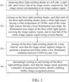
- the present disclosure provides a preprocessing method for improving image recognition, the preprocessing method being applied to recognize a target object in front of a driver's vehicle that being driven under dim light or severe weather conditions, the target object emitting a light with a color temperature of 3200K, the method being implemented through a preprocessing system for improving image recognition rate, the preprocessing system including an image sensor and at least one light emitting diode, the preprocessing method comprising: disposing the at least one light-emitting diode to surround the image sensor, in which the image sensor has an image capture region; turning on the at least one light-emitting diode, such that the at least one light-emitting diode emits at least one white light source having a color temperature of 3200K, in which the at least one white light source has a fixed illumination area range, and the illumination area range covers the image capture region, so that a color temperature of the image capture region is approximately or equal to 3200K; turning off the at least one light-emitting diode
- One of the beneficial effects of the present disclosure is that, by virtue of “disposing at least one light-emitting diode to surround an image sensor, in which the image sensor corresponds to an image capture region", "turning on the at least one light-emitting diode, such that the at least one light-emitting diode emits at least one white light source having a color temperature of 3200K, in which the at least one white light source has a fixed illumination area range, and the illumination area range covers the image capture region, so that a color temperature of the image capture region is approximately or equal to 3200K", and “turning off the at least one light-emitting diode for a time interval, such that the image sensor captures images to generate a preprocessing frame under a low illuminance condition between 0.0004 lux and 1 lux", the preprocessing method for improving image recognition provided in the present disclosure is capable of improving image recognition during nighttime and reducing misjudgments.
- a preprocessing system 100 for improving image recognition, and the preprocessing system is installed mainly on a vehicle for assisting recognition of objects in front of the vehicle when the vehicle is driven.
- a preprocessing system 100 provided in the present disclosure mainly includes an image sensor 1 and light-emitting diodes 2.
- the image sensor 1 and the light-emitting diodes 2 may be installed at any location on a vehicle for facilitating recognition of the objects in front of the vehicle, and the light-emitting diodes 2 can be disposed to surround the image sensor 1.
- the image sensor 1 can be a common image sensing member as seen in a digital camera or a smartphone, and can include a light sensing element and a processor (not shown in figures).
- the light sensing element is an element that transforms optical images into electrical signals, and can be a charge-coupled device (CCD) or a complementary metal oxide semiconductor (CMOS) active pixel sensor.
- CMOS complementary metal oxide semiconductor
- the processor is a frame signal processing chip. After the light sensing element receives light, the light is transformed into the electrical signal and then is transmitted to the processor. The processor then performs calculation, such as performing automatic white balance adjustment and automatic exposure adjustment, and generates a digital image that can be finally stored into a storage media.
- a lens of the digital camera is aimed at a target object.
- light emitted or reflected by the target object enters into the digital camera through the lens and is projected on the image sensor 1, such that a digital image of the target object is generated.
- a light receiving region of the image sensor 1 is an image capture region A.
- the image sensor 1 corresponds to the image capture region A (as shown in FIG. 3 ).
- a light-emitting diode is a white light LED that emits a white light source. More specifically, the white light LED used in the present disclosure is a white light LED having a color temperature of 3200K.
- a color temperature is a color of light. The higher the color temperature is, the closer to white the color of light will be, while the lower the color temperature is, the closer to yellow the color of light will be.
- a preprocessing method for improving image recognition is provided in the present disclosure, and includes steps as follows.
- Step S 1 referring to FIG. 2 , disposing three light-emitting diodes 2 at a left side, a right side, and a lower side of an image sensor 1, respectively, in which the image sensor 1 corresponds to an image capture region A.
- the present disclosure is not limited to the above-mentioned example.
- the quantity and positions of the light-emitting diodes 2 surrounding the image sensor 1 can be adjusted according to actual requirements.
- Step S2 referring to FIG. 3 , turning on the three light-emitting diodes 2, such that each of the three light-emitting diodes 2 emits a white light source having a color temperature of 3200K.
- Each of the white light sources has a fixed illumination area range 3.
- An arrangement of the three light-emitting diodes 2 and the image sensor 1 allows the illumination area ranges 3 of the three white light sources to cover the image capture region A, and at least half of the whole image capture region A is covered thereby.
- the three light-emitting diodes 2 are disposed at a left side, a right side, and a lower side of the image sensor 1, respectively, such that the illumination area ranges 3 of the three white light sources cover at least lower half of the whole image capture region A.
- Step S3 referring to FIG. 4 and FIG. 5 , turning off the three light-emitting diodes 2 for a time interval T, such that the image sensor 1 captures images to generate a preprocessing frame M under a low illuminance condition between 0.0004 lux and 1 lux.
- Step S4 repeatedly performing step S2 and step S3 to have the three light-emitting diodes 2 alternatingly turned on and turned off, such that the image sensor 1 generates a plurality of the preprocessing frames M for subsequent image recognition processing, as shown in FIG. 6 .
- the color temperature of the three white light sources is 3200K. Therefore, an overlapping region AA of the illumination area ranges 3 of the three white light sources in the image capture region A has a color temperature closer to or equal to 3200K. At this time, the image sensor 1 performs automatic white balance adjustment after receiving light, such that a frame predetermined to be captured also has a color temperature that is approximately or equal to 3200K.
- the light-emitting diodes 2 are turned off.
- the light-emitting diodes 2 are only turned on during nighttime or under severe weather conditions when recognition of objects ahead of the vehicle is performed, and the image sensor 1 begins to capture frames of the objects. Furthermore, the image sensor 1 generally captures N frames in one second. As such, when the light-emitting diodes 2 are turned on and the image sensor 1 begins to capture frames, the time required for completing automatic white balance adjustment is generally under one second.
- the image sensor 1 is under a low illuminance condition that is between 0.0004 lux and 1 lux.
- an illuminance received by the image sensor 1 is also decreased.
- the illuminance represents a luminous flux received by a unit area, and is measured in units of lux.
- the main technical feature of the present disclosure is that the image sensor 1 performs image capture at a time when the illuminance of the image sensor 1 is at the lowest, as shown in FIG. 7.
- FIG. 7 is a curve diagram of illuminance versus time when the image sensor 1 of the present disclosure receives light.
- the image sensor 1 stops receiving light. At the time the image sensor 1 stops receiving light, the illuminance of the image sensor 1 is decreased, and the image sensor 1 performs automatic exposure adjustment, such that the illuminance of the image sensor 1 returns to a balanced value.
- An area circled by broken lines in FIG.7 represents the time when an illuminance L is at the lowest (approximately between 0.0004 lux and 1 lux,), and a certain period of time has elapsed since turning off the light-emitting diodes 2. The certain period of time is the time interval T that is approximately between 10 milliseconds and 200 milliseconds.
- the illuminance of the image sensor 1 is decreased to 0.0004 lux at 200 milliseconds after turning off the light-emitting diodes 2.
- the image sensor 1 is still white balanced to the color temperature of 3200K at this time.
- the light-emitting diodes 2 After turning on the light-emitting diodes 2 such that the image capture region A corresponding to the image sensor 1 is white balanced, the light-emitting diodes 2 is turned off immediately, such that the illuminance (luminous flux that is received) of the image sensor 1 is decreased to as low as 0.0004 lux.
- the image sensor 1 is white balanced to (approximately or equal to) a color temperature of 3200K and is under a condition of low illuminance.
- the preprocessing frame M can be generated.
- the embodiment of the present disclosure is mainly applied to recognize a target object in front of a vehicle that is driven under dim light (e.g., nighttime) or severe weather conditions (e.g., rain or fog).
- the target object can be a pedestrian, other vehicles, etc.
- the target object can be an oncoming driven vehicle having a headlamp turned on.
- the image sensor 1 is aimed at the light-emitting headlamps of the oncoming vehicle and performs image capture.
- a color temperature of headlamps of the newly manufactured vehicle is maintained at 3200K. Therefore, by using the preprocessing method for improving image recognition of the present disclosure, in the preprocessing frame M generated by the image sensor 1 performing image capture on the light-emitting headlamps of the oncoming vehicle, a brightness (due to the image sensor 1 being maintained to be white balanced at a color temperature of 3200K) of the target object (i.e., the headlamp of the oncoming vehicle emitting a light having a color temperature of 3200K) can be further enhanced, and the surrounding environment can be further darkened (due to the image sensor 1 performing image capture under the condition of the lowest illuminance).
- the arrangement of the three light-emitting diodes 2 and the image sensor 1 allows the illumination area ranges 3 of the white light sources to cover the image capture region A.
- the illumination area ranges 3 of the three white light sources at least cover one half of the whole image capture region A. That is to say, a distance between the light-emitting diodes 2 and the image sensor 1 affects a size of the overlapping region AA of the illumination area ranges 3 in the image capture region A.
- a luminous intensity of light projected on the image sensor 1 by the light-emitting diodes 2 that are spaced apart from the image sensor 1 by a gap D is approximately equal to a luminous intensity of light projected on the image sensor 1 by an external light source at a predetermined distance from the image sensor 1.
- the term "luminous intensity”, also known in brief as “light intensity” or “luminosity”, represents a physical measure of the wavelength-weighted power emitted by a light source in a particular direction per unit solid angle, and is measured in units of candela.
- the light-emitting headlamp of the oncoming vehicle is the external light source. Since all oncoming vehicles approach the vehicle driven by the driver from an opposite direction, the predetermined distance is between 30 meters and 155 meters, and is preferably 155 meters. That is, when the oncoming vehicle is 155 meters from the vehicle of the driver, image recognition is required to be performed on the oncoming vehicle. Therefore, a luminous intensity of light projected on the image sensor 1 by the external light source at a predetermined distance of 155 meters from the image sensor 1 is equal to the luminous intensity of the light projected on the image sensor 1 by the light-emitting diodes 2 that are spaced apart from the image sensor 1 by the gap D.
- the gap D can be adjusted with the luminous intensity being fixed, or the luminous intensity of the light projected on the image sensor 1 by the light-emitting diodes 2 can be adjusted with the gap D being fixed.
- the gap D is adjusted to be between 10 millimeters and 15 millimeters.
- Another beneficial effect of the present disclosure is that, by virtue of "the image sensor 1 corresponding to the image capture region A", "the three light-emitting diodes 2 being disposed at a left side, a right side, and a lower side of the image sensor 1, respectively, each of the light-emitting diodes 2 emitting at least one white light source having a color temperature of 3200K, and each of the white light sources having a fixed illumination area range 3", “the illumination area ranges 3 of the three white light sources at least covering one half of the image capture region A, such that a color temperature of the covered half of the image capture region A being approximately or equal to 3200K", and "the image sensor 1 generating a preprocessing frame M under a low illuminance condition between 0.0004 lux and 1 lux, and the low illuminance condition is generated by turning on and off the three light-emitting diodes 2 once", the preprocessing system for improving image recognition provided in the present disclosure is capable of improving image recognition during nighttime and reducing misjudgments
- the white light LED that emit lights having a color temperature of 3200K is configured to surround the image sensor 1 and is alternatingly turned on and turned off.
- the image sensor 1 has a color temperature maintained at 3200K after undergoing automatic white balance adjustment, and is maintained at a low illuminance after undergoing automatic exposure adjustment.
- a brightness of the target object is further enhanced, and the surrounding environment is further darkened, which are advantageous for further performing image recognition process.
Landscapes
- Engineering & Computer Science (AREA)
- Multimedia (AREA)
- Physics & Mathematics (AREA)
- General Physics & Mathematics (AREA)
- Theoretical Computer Science (AREA)
- Signal Processing (AREA)
- Health & Medical Sciences (AREA)
- General Health & Medical Sciences (AREA)
- Vascular Medicine (AREA)
- Studio Devices (AREA)
- Color Television Image Signal Generators (AREA)
Claims (5)
- Vorverarbeitungsverfahren zum Verbessern der Bilderkennung eines Zielobjekts vor einem Fahrzeug eines Fahrers bei schwachem Licht oder schlechten Wetterbedingungen unter Verwendung eines Vorverarbeitungssystems, welches einen Bildsensor (1) mit Weißabgleich und mindestens eine lichtemittierende Diode (2) aufweist,
wobei das Vorverarbeitungsverfahren aufweist:Anordnen der mindestens einen lichtemittierenden Diode (2) so, dass sie den Bildsensor (1) umgibt, wobei der Bildsensor (1) einen Bilderfassungsbereich (A) hat;Einschalten der mindestens einen lichtemittierenden Diode (2) derart, dass die mindestens eine lichtemittierende Diode (2) mindestens ein weißes Licht mit einer Farbtemperatur von 3200 K emittiert, mit einem festen Beleuchtungsflächenbereich (3), und wobei der Beleuchtungsflächenbereich (3) den Bilderfassungsbereich (A) abdeckt, so dass eine Farbtemperatur des Bilderfassungsbereichs (A) ungefähr oder gleich 3200 K beträgt;Ausschalten der mindestens einen lichtemittierenden Diode (2) für ein Zeitintervall derart, dass der Bildsensor (1) Bilder erfasst, um einen Vorverarbeitung-Frame (M) bei einer Niedrige-Beleuchtungsstärke-Bedingung zu erzeugen, welche zwischen 0,0004 Lux und 1 Lux liegt; undabwechselndes Ein- und Ausschalten der lichtemittierenden Diode (2) derart, dass der Bildsensor (1) mehrere Vorverarbeitung-Frames (M) erzeugt. - Vorverarbeitungsverfahren gemäß Anspruch 1, wobei das Zeitintervall zwischen 10 Millisekunden und 200 Millisekunden beträgt.
- Vorverarbeitungsverfahren gemäß Anspruch 1, wobei die mindestens eine lichtemittierende Diode (2) von dem Bildsensor (1) aus mittels eines Spalts (D) beabstandet ist, und eine Leuchtintensität des mittels des Zielobjekts aus emittierten Lichts, welche mittels der mindestens einen lichtemittierenden Diode (2) auf den Bildsensor (1) projiziert wird, gleich einer Leuchtintensität des Lichts ist, welches mittels einer externen Lichtquelle in einem vorbestimmten Abstand von dem Bildsensor (1) auf den Bildsensor (1) projiziert wird, wobei der vorbestimmte Abstand der Abstand zwischen dem Zielobjekt und dem Fahrzeug des Fahrers ist, und wobei das Zielobjekt beginnt, mittels des Vorverarbeitungssystem detektiert zu werden, wenn das Zielobjekt sich in dem vorbestimmten Abstand befindet.
- Vorverarbeitungsverfahren gemäß Anspruch 3, wobei der Spalt (D) zwischen 10 Millimetern und 15 Millimetern beträgt.
- Vorverarbeitungsverfahren gemäß Anspruch 3, wobei der vorbestimmte Abstand zwischen 30 Metern und 155 Metern beträgt.
Applications Claiming Priority (1)
| Application Number | Priority Date | Filing Date | Title |
|---|---|---|---|
| TW109132683A TWI751717B (zh) | 2020-09-22 | 2020-09-22 | 提升影像辨識率的前處理方法及系統 |
Publications (2)
| Publication Number | Publication Date |
|---|---|
| EP3971769A1 EP3971769A1 (de) | 2022-03-23 |
| EP3971769B1 true EP3971769B1 (de) | 2025-01-08 |
Family
ID=74183050
Family Applications (1)
| Application Number | Title | Priority Date | Filing Date |
|---|---|---|---|
| EP21151322.1A Active EP3971769B1 (de) | 2020-09-22 | 2021-01-13 | Vorverarbeitungsverfahren zur verbesserung der bilderkennung |
Country Status (4)
| Country | Link |
|---|---|
| US (1) | US11688152B2 (de) |
| EP (1) | EP3971769B1 (de) |
| CN (1) | CN112422932B (de) |
| TW (1) | TWI751717B (de) |
Families Citing this family (1)
| Publication number | Priority date | Publication date | Assignee | Title |
|---|---|---|---|---|
| KR102805761B1 (ko) * | 2023-11-22 | 2025-05-13 | (주)비전고 | 적응형 저조도 이미지 개선 방법 및 컴퓨팅시스템 |
Citations (1)
| Publication number | Priority date | Publication date | Assignee | Title |
|---|---|---|---|---|
| EP1964718B1 (de) * | 2007-02-27 | 2020-03-18 | Hitachi, Ltd. | Bildverarbeitungsvorrichtung, Bildverarbeitungsverfahren und Bildverarbeitungssystem |
Family Cites Families (16)
| Publication number | Priority date | Publication date | Assignee | Title |
|---|---|---|---|---|
| US20030160889A1 (en) * | 2002-02-22 | 2003-08-28 | Gerald Angeli | Camera with led lighting source for illuminating a scene to be photographed |
| JP2007174563A (ja) * | 2005-12-26 | 2007-07-05 | Ricoh Co Ltd | 撮像装置 |
| JP4835578B2 (ja) * | 2007-11-09 | 2011-12-14 | ソニー株式会社 | 表示撮像装置、物体検出プログラムおよび物体の検出方法 |
| JP2009259703A (ja) | 2008-04-18 | 2009-11-05 | Olympus Corp | 照明装置、画像取得装置 |
| CN102279504A (zh) * | 2010-06-11 | 2011-12-14 | 特佳光电股份有限公司 | 摄影机的白光辅助照明控制方法 |
| US8743275B1 (en) * | 2010-12-15 | 2014-06-03 | Google Inc. | Mobile communication device with multiple flashpoints |
| JP5999483B2 (ja) * | 2011-11-02 | 2016-09-28 | 株式会社リコー | 付着物検出装置および車載機器制御装置 |
| JP5979880B2 (ja) * | 2012-01-06 | 2016-08-31 | キヤノン株式会社 | 照明装置及び撮像システム |
| JP2014219602A (ja) * | 2013-05-09 | 2014-11-20 | オリンパス株式会社 | 撮影装置 |
| CN104834152B (zh) * | 2014-02-08 | 2019-02-26 | 深圳富泰宏精密工业有限公司 | 控制相机闪光灯拍照的系统与方法 |
| JP6533050B2 (ja) | 2014-11-13 | 2019-06-19 | クラリオン株式会社 | 車載カメラシステム |
| US10560188B2 (en) * | 2015-02-17 | 2020-02-11 | Kookmin University Industry Academy Cooperation Foundation | Image sensor communication system and communication method using rolling shutter modulation |
| US9563798B1 (en) | 2016-08-23 | 2017-02-07 | V.L. Engineering, Inc. | Reading invisible barcodes and other invisible insignia using physically unmodified smartphone |
| US10992876B2 (en) | 2016-10-18 | 2021-04-27 | Texas Instruments Incorporated | WDR imaging with LED flicker mitigation |
| JP6935815B2 (ja) * | 2017-03-21 | 2021-09-15 | コニカミノルタ株式会社 | 照明撮像装置 |
| TWI711005B (zh) * | 2019-03-14 | 2020-11-21 | 宏碁股份有限公司 | 影像亮度調整方法及計算機程式產品 |
-
2020
- 2020-09-22 TW TW109132683A patent/TWI751717B/zh active
- 2020-11-06 CN CN202011231283.2A patent/CN112422932B/zh not_active Expired - Fee Related
-
2021
- 2021-01-06 US US17/142,512 patent/US11688152B2/en active Active
- 2021-01-13 EP EP21151322.1A patent/EP3971769B1/de active Active
Patent Citations (1)
| Publication number | Priority date | Publication date | Assignee | Title |
|---|---|---|---|---|
| EP1964718B1 (de) * | 2007-02-27 | 2020-03-18 | Hitachi, Ltd. | Bildverarbeitungsvorrichtung, Bildverarbeitungsverfahren und Bildverarbeitungssystem |
Also Published As
| Publication number | Publication date |
|---|---|
| US20220094835A1 (en) | 2022-03-24 |
| EP3971769A1 (de) | 2022-03-23 |
| TWI751717B (zh) | 2022-01-01 |
| US11688152B2 (en) | 2023-06-27 |
| CN112422932A (zh) | 2021-02-26 |
| TW202213174A (zh) | 2022-04-01 |
| CN112422932B (zh) | 2022-10-11 |
Similar Documents
| Publication | Publication Date | Title |
|---|---|---|
| US10688911B2 (en) | Illumination apparatus | |
| CN103907011B (zh) | 附着物检测器和车辆装备控制装置 | |
| US8401231B2 (en) | Sustainable outdoor lighting system for use in environmentally photo-sensitive area | |
| US20080205705A1 (en) | Image Processing Apparatus, Image Processing Method and Image Processing System | |
| JP4824598B2 (ja) | 車両用ランプシステム | |
| EP3971769B1 (de) | Vorverarbeitungsverfahren zur verbesserung der bilderkennung | |
| EP3605497A1 (de) | Vorrichtung zur beleuchtungsbildaufnahme | |
| JP7136055B2 (ja) | 露光制御装置 | |
| US11657526B2 (en) | Distance measurement device | |
| KR101350861B1 (ko) | 빛의 파장인식기능을 이용한 감시카메라 시스템의 적외선 엘이디 제어장치 및 방법 | |
| KR100554501B1 (ko) | 감시카메라의 역광차단장치 | |
| US20240101021A1 (en) | Headlight determination apparatus | |
| KR101949658B1 (ko) | Cctv 야간차량번호 인식을 위한 동기화 컨트롤러가 탑재된 조명장치 | |
| US12028621B2 (en) | Object detection system for a motor vehicle | |
| CN114787881B (zh) | 用于交通工具的组件、照明单元、交通工具以及包括组件的交通工具 | |
| JP2000251191A (ja) | ナンバ読取装置 | |
| JP2008273257A (ja) | 車両用カメラシステム | |
| JP6944310B2 (ja) | 特定対象物検出装置 | |
| CN117068037A (zh) | 一种高分辨率led行车信息投射系统 | |
| CN116963337A (zh) | 前照灯、车辆及前照灯的控制方法 | |
| JP2021044667A (ja) | 露光制御装置 |
Legal Events
| Date | Code | Title | Description |
|---|---|---|---|
| PUAI | Public reference made under article 153(3) epc to a published international application that has entered the european phase |
Free format text: ORIGINAL CODE: 0009012 |
|
| STAA | Information on the status of an ep patent application or granted ep patent |
Free format text: STATUS: THE APPLICATION HAS BEEN PUBLISHED |
|
| AK | Designated contracting states |
Kind code of ref document: A1 Designated state(s): AL AT BE BG CH CY CZ DE DK EE ES FI FR GB GR HR HU IE IS IT LI LT LU LV MC MK MT NL NO PL PT RO RS SE SI SK SM TR |
|
| STAA | Information on the status of an ep patent application or granted ep patent |
Free format text: STATUS: REQUEST FOR EXAMINATION WAS MADE |
|
| 17P | Request for examination filed |
Effective date: 20220909 |
|
| RBV | Designated contracting states (corrected) |
Designated state(s): AL AT BE BG CH CY CZ DE DK EE ES FI FR GB GR HR HU IE IS IT LI LT LU LV MC MK MT NL NO PL PT RO RS SE SI SK SM TR |
|
| REG | Reference to a national code |
Ref legal event code: R079 Ref country code: DE Ref legal event code: R079 Ref document number: 602021024537 Country of ref document: DE Free format text: PREVIOUS MAIN CLASS: G06K0009000000 Ipc: G06V0010141000 |
|
| GRAP | Despatch of communication of intention to grant a patent |
Free format text: ORIGINAL CODE: EPIDOSNIGR1 |
|
| STAA | Information on the status of an ep patent application or granted ep patent |
Free format text: STATUS: GRANT OF PATENT IS INTENDED |
|
| RIC1 | Information provided on ipc code assigned before grant |
Ipc: G06V 10/147 20220101ALI20240923BHEP Ipc: G06V 10/141 20220101AFI20240923BHEP |
|
| INTG | Intention to grant announced |
Effective date: 20241008 |
|
| GRAS | Grant fee paid |
Free format text: ORIGINAL CODE: EPIDOSNIGR3 |
|
| GRAA | (expected) grant |
Free format text: ORIGINAL CODE: 0009210 |
|
| STAA | Information on the status of an ep patent application or granted ep patent |
Free format text: STATUS: THE PATENT HAS BEEN GRANTED |
|
| AK | Designated contracting states |
Kind code of ref document: B1 Designated state(s): AL AT BE BG CH CY CZ DE DK EE ES FI FR GB GR HR HU IE IS IT LI LT LU LV MC MK MT NL NO PL PT RO RS SE SI SK SM TR |
|
| REG | Reference to a national code |
Ref country code: GB Ref legal event code: FG4D |
|
| REG | Reference to a national code |
Ref country code: CH Ref legal event code: EP |
|
| REG | Reference to a national code |
Ref country code: DE Ref legal event code: R096 Ref document number: 602021024537 Country of ref document: DE |
|
| REG | Reference to a national code |
Ref country code: IE Ref legal event code: FG4D |
|
| PGFP | Annual fee paid to national office [announced via postgrant information from national office to epo] |
Ref country code: DE Payment date: 20250113 Year of fee payment: 5 |
|
| PGFP | Annual fee paid to national office [announced via postgrant information from national office to epo] |
Ref country code: AT Payment date: 20250417 Year of fee payment: 5 |
|
| REG | Reference to a national code |
Ref country code: LT Ref legal event code: MG9D |
|
| REG | Reference to a national code |
Ref country code: NL Ref legal event code: MP Effective date: 20250108 |
|
| REG | Reference to a national code |
Ref country code: AT Ref legal event code: MK05 Ref document number: 1758845 Country of ref document: AT Kind code of ref document: T Effective date: 20250108 |
|
| PG25 | Lapsed in a contracting state [announced via postgrant information from national office to epo] |
Ref country code: NL Free format text: LAPSE BECAUSE OF FAILURE TO SUBMIT A TRANSLATION OF THE DESCRIPTION OR TO PAY THE FEE WITHIN THE PRESCRIBED TIME-LIMIT Effective date: 20250108 |
|
| PG25 | Lapsed in a contracting state [announced via postgrant information from national office to epo] |
Ref country code: RS Free format text: LAPSE BECAUSE OF FAILURE TO SUBMIT A TRANSLATION OF THE DESCRIPTION OR TO PAY THE FEE WITHIN THE PRESCRIBED TIME-LIMIT Effective date: 20250408 |
|
| PG25 | Lapsed in a contracting state [announced via postgrant information from national office to epo] |
Ref country code: FI Free format text: LAPSE BECAUSE OF FAILURE TO SUBMIT A TRANSLATION OF THE DESCRIPTION OR TO PAY THE FEE WITHIN THE PRESCRIBED TIME-LIMIT Effective date: 20250108 |
|
| PG25 | Lapsed in a contracting state [announced via postgrant information from national office to epo] |
Ref country code: PL Free format text: LAPSE BECAUSE OF FAILURE TO SUBMIT A TRANSLATION OF THE DESCRIPTION OR TO PAY THE FEE WITHIN THE PRESCRIBED TIME-LIMIT Effective date: 20250108 |
|
| PG25 | Lapsed in a contracting state [announced via postgrant information from national office to epo] |
Ref country code: ES Free format text: LAPSE BECAUSE OF FAILURE TO SUBMIT A TRANSLATION OF THE DESCRIPTION OR TO PAY THE FEE WITHIN THE PRESCRIBED TIME-LIMIT Effective date: 20250108 |
|
| PG25 | Lapsed in a contracting state [announced via postgrant information from national office to epo] |
Ref country code: IS Free format text: LAPSE BECAUSE OF FAILURE TO SUBMIT A TRANSLATION OF THE DESCRIPTION OR TO PAY THE FEE WITHIN THE PRESCRIBED TIME-LIMIT Effective date: 20250508 Ref country code: NO Free format text: LAPSE BECAUSE OF FAILURE TO SUBMIT A TRANSLATION OF THE DESCRIPTION OR TO PAY THE FEE WITHIN THE PRESCRIBED TIME-LIMIT Effective date: 20250408 |
|
| PG25 | Lapsed in a contracting state [announced via postgrant information from national office to epo] |
Ref country code: HR Free format text: LAPSE BECAUSE OF FAILURE TO SUBMIT A TRANSLATION OF THE DESCRIPTION OR TO PAY THE FEE WITHIN THE PRESCRIBED TIME-LIMIT Effective date: 20250108 |
|
| PG25 | Lapsed in a contracting state [announced via postgrant information from national office to epo] |
Ref country code: PT Free format text: LAPSE BECAUSE OF FAILURE TO SUBMIT A TRANSLATION OF THE DESCRIPTION OR TO PAY THE FEE WITHIN THE PRESCRIBED TIME-LIMIT Effective date: 20250508 Ref country code: LV Free format text: LAPSE BECAUSE OF FAILURE TO SUBMIT A TRANSLATION OF THE DESCRIPTION OR TO PAY THE FEE WITHIN THE PRESCRIBED TIME-LIMIT Effective date: 20250108 |
|
| PG25 | Lapsed in a contracting state [announced via postgrant information from national office to epo] |
Ref country code: GR Free format text: LAPSE BECAUSE OF FAILURE TO SUBMIT A TRANSLATION OF THE DESCRIPTION OR TO PAY THE FEE WITHIN THE PRESCRIBED TIME-LIMIT Effective date: 20250409 Ref country code: BG Free format text: LAPSE BECAUSE OF FAILURE TO SUBMIT A TRANSLATION OF THE DESCRIPTION OR TO PAY THE FEE WITHIN THE PRESCRIBED TIME-LIMIT Effective date: 20250108 |
|
| PG25 | Lapsed in a contracting state [announced via postgrant information from national office to epo] |
Ref country code: AT Free format text: LAPSE BECAUSE OF FAILURE TO SUBMIT A TRANSLATION OF THE DESCRIPTION OR TO PAY THE FEE WITHIN THE PRESCRIBED TIME-LIMIT Effective date: 20250108 |
|
| REG | Reference to a national code |
Ref country code: CH Ref legal event code: PL |
|
| PG25 | Lapsed in a contracting state [announced via postgrant information from national office to epo] |
Ref country code: SE Free format text: LAPSE BECAUSE OF FAILURE TO SUBMIT A TRANSLATION OF THE DESCRIPTION OR TO PAY THE FEE WITHIN THE PRESCRIBED TIME-LIMIT Effective date: 20250108 |
|
| PG25 | Lapsed in a contracting state [announced via postgrant information from national office to epo] |
Ref country code: LU Free format text: LAPSE BECAUSE OF NON-PAYMENT OF DUE FEES Effective date: 20250113 |
|
| PG25 | Lapsed in a contracting state [announced via postgrant information from national office to epo] |
Ref country code: SM Free format text: LAPSE BECAUSE OF FAILURE TO SUBMIT A TRANSLATION OF THE DESCRIPTION OR TO PAY THE FEE WITHIN THE PRESCRIBED TIME-LIMIT Effective date: 20250108 |
|
| REG | Reference to a national code |
Ref country code: DE Ref legal event code: R097 Ref document number: 602021024537 Country of ref document: DE |
|
| PG25 | Lapsed in a contracting state [announced via postgrant information from national office to epo] |
Ref country code: DK Free format text: LAPSE BECAUSE OF FAILURE TO SUBMIT A TRANSLATION OF THE DESCRIPTION OR TO PAY THE FEE WITHIN THE PRESCRIBED TIME-LIMIT Effective date: 20250108 |
|
| PG25 | Lapsed in a contracting state [announced via postgrant information from national office to epo] |
Ref country code: MC Free format text: LAPSE BECAUSE OF FAILURE TO SUBMIT A TRANSLATION OF THE DESCRIPTION OR TO PAY THE FEE WITHIN THE PRESCRIBED TIME-LIMIT Effective date: 20250108 |
|
| PG25 | Lapsed in a contracting state [announced via postgrant information from national office to epo] |
Ref country code: BE Free format text: LAPSE BECAUSE OF NON-PAYMENT OF DUE FEES Effective date: 20250131 |
|
| PG25 | Lapsed in a contracting state [announced via postgrant information from national office to epo] |
Ref country code: CH Free format text: LAPSE BECAUSE OF NON-PAYMENT OF DUE FEES Effective date: 20250131 |
|
| PG25 | Lapsed in a contracting state [announced via postgrant information from national office to epo] |
Ref country code: CZ Free format text: LAPSE BECAUSE OF FAILURE TO SUBMIT A TRANSLATION OF THE DESCRIPTION OR TO PAY THE FEE WITHIN THE PRESCRIBED TIME-LIMIT Effective date: 20250108 Ref country code: EE Free format text: LAPSE BECAUSE OF FAILURE TO SUBMIT A TRANSLATION OF THE DESCRIPTION OR TO PAY THE FEE WITHIN THE PRESCRIBED TIME-LIMIT Effective date: 20250108 |
|
| REG | Reference to a national code |
Ref country code: BE Ref legal event code: MM Effective date: 20250131 |
|
| PG25 | Lapsed in a contracting state [announced via postgrant information from national office to epo] |
Ref country code: RO Free format text: LAPSE BECAUSE OF FAILURE TO SUBMIT A TRANSLATION OF THE DESCRIPTION OR TO PAY THE FEE WITHIN THE PRESCRIBED TIME-LIMIT Effective date: 20250108 |
|
| PG25 | Lapsed in a contracting state [announced via postgrant information from national office to epo] |
Ref country code: SK Free format text: LAPSE BECAUSE OF FAILURE TO SUBMIT A TRANSLATION OF THE DESCRIPTION OR TO PAY THE FEE WITHIN THE PRESCRIBED TIME-LIMIT Effective date: 20250108 |
|
| PLBE | No opposition filed within time limit |
Free format text: ORIGINAL CODE: 0009261 |
|
| STAA | Information on the status of an ep patent application or granted ep patent |
Free format text: STATUS: NO OPPOSITION FILED WITHIN TIME LIMIT |
|
| 26N | No opposition filed |
Effective date: 20251009 |
|
| GBPC | Gb: european patent ceased through non-payment of renewal fee |
Effective date: 20250408 |
|
| PG25 | Lapsed in a contracting state [announced via postgrant information from national office to epo] |
Ref country code: GB Free format text: LAPSE BECAUSE OF NON-PAYMENT OF DUE FEES Effective date: 20250408 |
|
| PG25 | Lapsed in a contracting state [announced via postgrant information from national office to epo] |
Ref country code: FR Free format text: LAPSE BECAUSE OF NON-PAYMENT OF DUE FEES Effective date: 20250308 |
|
| PG25 | Lapsed in a contracting state [announced via postgrant information from national office to epo] |
Ref country code: IE Free format text: LAPSE BECAUSE OF NON-PAYMENT OF DUE FEES Effective date: 20250113 |
|
| PG25 | Lapsed in a contracting state [announced via postgrant information from national office to epo] |
Ref country code: IT Free format text: LAPSE BECAUSE OF FAILURE TO SUBMIT A TRANSLATION OF THE DESCRIPTION OR TO PAY THE FEE WITHIN THE PRESCRIBED TIME-LIMIT Effective date: 20250108 |