EP3971673A1 - Planar-beam, light detection and ranging system - Google Patents
Planar-beam, light detection and ranging system Download PDFInfo
- Publication number
- EP3971673A1 EP3971673A1 EP21208121.0A EP21208121A EP3971673A1 EP 3971673 A1 EP3971673 A1 EP 3971673A1 EP 21208121 A EP21208121 A EP 21208121A EP 3971673 A1 EP3971673 A1 EP 3971673A1
- Authority
- EP
- European Patent Office
- Prior art keywords
- pladar
- photodetectors
- data
- autonomous vehicle
- lidar system
- Prior art date
- Legal status (The legal status is an assumption and is not a legal conclusion. Google has not performed a legal analysis and makes no representation as to the accuracy of the status listed.)
- Pending
Links
- 238000001514 detection method Methods 0.000 title claims abstract description 12
- 238000000034 method Methods 0.000 claims description 21
- 230000001133 acceleration Effects 0.000 claims description 12
- 239000000835 fiber Substances 0.000 claims description 7
- 230000008569 process Effects 0.000 claims description 7
- 238000012545 processing Methods 0.000 description 41
- 230000007423 decrease Effects 0.000 description 14
- 238000010586 diagram Methods 0.000 description 7
- 238000003860 storage Methods 0.000 description 7
- 238000004891 communication Methods 0.000 description 5
- 238000013507 mapping Methods 0.000 description 5
- 230000008901 benefit Effects 0.000 description 4
- 230000003247 decreasing effect Effects 0.000 description 4
- 230000004044 response Effects 0.000 description 4
- 230000000694 effects Effects 0.000 description 3
- 238000005516 engineering process Methods 0.000 description 3
- 230000006870 function Effects 0.000 description 3
- 230000003287 optical effect Effects 0.000 description 3
- 230000035945 sensitivity Effects 0.000 description 3
- 230000026676 system process Effects 0.000 description 3
- 241001465754 Metazoa Species 0.000 description 2
- 230000001413 cellular effect Effects 0.000 description 2
- 238000005070 sampling Methods 0.000 description 2
- 230000003595 spectral effect Effects 0.000 description 2
- 230000003068 static effect Effects 0.000 description 2
- 238000003491 array Methods 0.000 description 1
- 238000004364 calculation method Methods 0.000 description 1
- 230000008859 change Effects 0.000 description 1
- 238000004590 computer program Methods 0.000 description 1
- 238000005520 cutting process Methods 0.000 description 1
- 230000007613 environmental effect Effects 0.000 description 1
- 231100001261 hazardous Toxicity 0.000 description 1
- 230000036541 health Effects 0.000 description 1
- 230000004807 localization Effects 0.000 description 1
- 238000004519 manufacturing process Methods 0.000 description 1
- 230000005055 memory storage Effects 0.000 description 1
- 239000002184 metal Substances 0.000 description 1
- 238000012986 modification Methods 0.000 description 1
- 230000004048 modification Effects 0.000 description 1
- 239000011435 rock Substances 0.000 description 1
- 239000004065 semiconductor Substances 0.000 description 1
- 238000012163 sequencing technique Methods 0.000 description 1
- 239000007787 solid Substances 0.000 description 1
- 238000012360 testing method Methods 0.000 description 1
- 239000002699 waste material Substances 0.000 description 1
Images


Classifications
-
- G—PHYSICS
- G05—CONTROLLING; REGULATING
- G05D—SYSTEMS FOR CONTROLLING OR REGULATING NON-ELECTRIC VARIABLES
- G05D1/00—Control of position, course or altitude of land, water, air, or space vehicles, e.g. automatic pilot
- G05D1/02—Control of position or course in two dimensions
- G05D1/021—Control of position or course in two dimensions specially adapted to land vehicles
- G05D1/0231—Control of position or course in two dimensions specially adapted to land vehicles using optical position detecting means
- G05D1/0238—Control of position or course in two dimensions specially adapted to land vehicles using optical position detecting means using obstacle or wall sensors
- G05D1/024—Control of position or course in two dimensions specially adapted to land vehicles using optical position detecting means using obstacle or wall sensors in combination with a laser
-
- G—PHYSICS
- G01—MEASURING; TESTING
- G01C—MEASURING DISTANCES, LEVELS OR BEARINGS; SURVEYING; NAVIGATION; GYROSCOPIC INSTRUMENTS; PHOTOGRAMMETRY OR VIDEOGRAMMETRY
- G01C21/00—Navigation; Navigational instruments not provided for in groups G01C1/00 - G01C19/00
- G01C21/26—Navigation; Navigational instruments not provided for in groups G01C1/00 - G01C19/00 specially adapted for navigation in a road network
- G01C21/34—Route searching; Route guidance
-
- G—PHYSICS
- G01—MEASURING; TESTING
- G01S—RADIO DIRECTION-FINDING; RADIO NAVIGATION; DETERMINING DISTANCE OR VELOCITY BY USE OF RADIO WAVES; LOCATING OR PRESENCE-DETECTING BY USE OF THE REFLECTION OR RERADIATION OF RADIO WAVES; ANALOGOUS ARRANGEMENTS USING OTHER WAVES
- G01S17/00—Systems using the reflection or reradiation of electromagnetic waves other than radio waves, e.g. lidar systems
- G01S17/88—Lidar systems specially adapted for specific applications
- G01S17/93—Lidar systems specially adapted for specific applications for anti-collision purposes
- G01S17/931—Lidar systems specially adapted for specific applications for anti-collision purposes of land vehicles
-
- G—PHYSICS
- G01—MEASURING; TESTING
- G01S—RADIO DIRECTION-FINDING; RADIO NAVIGATION; DETERMINING DISTANCE OR VELOCITY BY USE OF RADIO WAVES; LOCATING OR PRESENCE-DETECTING BY USE OF THE REFLECTION OR RERADIATION OF RADIO WAVES; ANALOGOUS ARRANGEMENTS USING OTHER WAVES
- G01S7/00—Details of systems according to groups G01S13/00, G01S15/00, G01S17/00
- G01S7/48—Details of systems according to groups G01S13/00, G01S15/00, G01S17/00 of systems according to group G01S17/00
- G01S7/481—Constructional features, e.g. arrangements of optical elements
- G01S7/4814—Constructional features, e.g. arrangements of optical elements of transmitters alone
- G01S7/4815—Constructional features, e.g. arrangements of optical elements of transmitters alone using multiple transmitters
-
- G—PHYSICS
- G01—MEASURING; TESTING
- G01S—RADIO DIRECTION-FINDING; RADIO NAVIGATION; DETERMINING DISTANCE OR VELOCITY BY USE OF RADIO WAVES; LOCATING OR PRESENCE-DETECTING BY USE OF THE REFLECTION OR RERADIATION OF RADIO WAVES; ANALOGOUS ARRANGEMENTS USING OTHER WAVES
- G01S7/00—Details of systems according to groups G01S13/00, G01S15/00, G01S17/00
- G01S7/48—Details of systems according to groups G01S13/00, G01S15/00, G01S17/00 of systems according to group G01S17/00
- G01S7/481—Constructional features, e.g. arrangements of optical elements
- G01S7/4816—Constructional features, e.g. arrangements of optical elements of receivers alone
-
- G—PHYSICS
- G01—MEASURING; TESTING
- G01S—RADIO DIRECTION-FINDING; RADIO NAVIGATION; DETERMINING DISTANCE OR VELOCITY BY USE OF RADIO WAVES; LOCATING OR PRESENCE-DETECTING BY USE OF THE REFLECTION OR RERADIATION OF RADIO WAVES; ANALOGOUS ARRANGEMENTS USING OTHER WAVES
- G01S7/00—Details of systems according to groups G01S13/00, G01S15/00, G01S17/00
- G01S7/48—Details of systems according to groups G01S13/00, G01S15/00, G01S17/00 of systems according to group G01S17/00
- G01S7/481—Constructional features, e.g. arrangements of optical elements
- G01S7/4817—Constructional features, e.g. arrangements of optical elements relating to scanning
-
- G—PHYSICS
- G01—MEASURING; TESTING
- G01S—RADIO DIRECTION-FINDING; RADIO NAVIGATION; DETERMINING DISTANCE OR VELOCITY BY USE OF RADIO WAVES; LOCATING OR PRESENCE-DETECTING BY USE OF THE REFLECTION OR RERADIATION OF RADIO WAVES; ANALOGOUS ARRANGEMENTS USING OTHER WAVES
- G01S7/00—Details of systems according to groups G01S13/00, G01S15/00, G01S17/00
- G01S7/48—Details of systems according to groups G01S13/00, G01S15/00, G01S17/00 of systems according to group G01S17/00
- G01S7/497—Means for monitoring or calibrating
- G01S7/4972—Alignment of sensor
-
- G—PHYSICS
- G05—CONTROLLING; REGULATING
- G05D—SYSTEMS FOR CONTROLLING OR REGULATING NON-ELECTRIC VARIABLES
- G05D1/00—Control of position, course or altitude of land, water, air, or space vehicles, e.g. automatic pilot
- G05D1/0088—Control of position, course or altitude of land, water, air, or space vehicles, e.g. automatic pilot characterized by the autonomous decision making process, e.g. artificial intelligence, predefined behaviours
-
- G—PHYSICS
- G05—CONTROLLING; REGULATING
- G05D—SYSTEMS FOR CONTROLLING OR REGULATING NON-ELECTRIC VARIABLES
- G05D1/00—Control of position, course or altitude of land, water, air, or space vehicles, e.g. automatic pilot
- G05D1/02—Control of position or course in two dimensions
- G05D1/021—Control of position or course in two dimensions specially adapted to land vehicles
- G05D1/0231—Control of position or course in two dimensions specially adapted to land vehicles using optical position detecting means
- G05D1/0246—Control of position or course in two dimensions specially adapted to land vehicles using optical position detecting means using a video camera in combination with image processing means
- G05D1/0251—Control of position or course in two dimensions specially adapted to land vehicles using optical position detecting means using a video camera in combination with image processing means extracting 3D information from a plurality of images taken from different locations, e.g. stereo vision
Definitions
- Light detection, and ranging (LIDAR or LADAR) systems utilize a number of laser beams to detect reflectance or backscatter from the laser beams to map surface features or for remote sensing.
- LIDAR Light detection, and ranging
- each beam is precisely configured with a dedicated photodetector that detects the reflectance and/or backscatter from that particular beam. As the beam count increases, so do cost and space requirements for the individual lasers and photodetectors.
- LIDAR technology involves fixed-beam LIDAR systems that include laser sources, scanners, optical systems (e.g., beam splitters and/or collimators), and photodetectors.
- cutting edge LIDAR systems can include pulse rates on the order of one million pulses per second producing a detailed point cloud map of an autonomous vehicle's surroundings at ranges upwards of one hundred-plus meters.
- These LIDAR systems require precision pulse sequencing for the laser beams for multiple reasons, such as power constraints, sampling and/or processing constraints, and the like.
- operational speed may be limited by the nature of the beam pattern produced by the LIDAR system.
- a LIDAR system may require several separate beams to readily detect potential hazards with sufficient granularity to decelerate, maneuver, and/or stop the autonomous vehicle accordingly.
- a fixed-beam LIDAR system may require well over seventy separate beams.
- LIDAR Low-power laser desorption spectroscopy
- the LIDAR system will require more power, greater processing capability, larger or more sensitive photodetector and receiving equipment, constrained optics, and generally greater weight and more space.
- cost and waste quickly become an issue when increasing the number of fixed-beams, since the beam pattern for the fixed-beam LIDAR system must be tuned for a maximum operational speed of the autonomous vehicle. If autonomous vehicles are to operate safely with LIDAR technology on public highways at high speed, then alternative arrangements may be necessary to avoid spiraling costs, wasted power, additional equipment, and increased processing requirements.
- the PLADAR system can include a laser scanner that emits a planar-beam, and a detector array to detect reflected light (e.g., backscatter) from the planar beam.
- the laser scanner can include a collimation component that collimates a laser beam generated by the laser scanner into the planar beam.
- the laser scanner can utilize a single laser collimated on an axis (e.g., a vertical axis) to generate the planar beam, which can extend from the laser scanner approximately triangularly as opposed to linearly.
- the laser scanner can include a fiber laser that generates the laser beam for axial collimation.
- Fiber lasers can offer vibrational stability, ideal optical quality, and compact size in addition to other desirable qualities.
- any type of laser with appropriate emission characteristics may be used, such as certain types of gas lasers, excimer lasers, dye lasers, other forms of solid state lasers, semi-conductor based lasers, metal vapor lasers, etc. utilizing continuous wave or pulsed emissions.
- wavelengths on the order of 1000 nanometers (nm) e.g., 1200-1550 nm
- nm nanometers
- the detector array of the PLADAR system can include at least one set of photodetectors, such as one or more linear rows of photodetectors, which can be included on a circuit board of the PLADAR system.
- the circuit board can include a number of adjustment components for the photodetector array(s) to calibrate the photodetectors in concert.
- the PLADAR system can further include an adjustment controller to dynamically adjust the adjustment components to optimally configure the row(s) of photodetectors in response to a command signal.
- the command signal may be generated by a calibration system pre-implementation, or dynamically when the PLADAR system is in use.
- the adjustment components can be tuned manually by a user or technician when calibrating the photodetector array to the planar beam.
- the PLADAR system can be implemented on an autonomous vehicle to provide sensor data to an on-board data processing system of the autonomous vehicle.
- the PLADAR system can include an analog-to-digital converter (ADC) chain coupled to the photodetector array.
- ADC analog-to-digital converter
- the ADC chain can generate output from all of the photodetectors simultaneously, and the outputted data can be processed (e.g., by the on-board data processing system of the autonomous vehicle) accordingly.
- the pulse rate of the planar beam can be significantly reduced compared to fixed-beam LIDAR systems.
- examples described herein can transmit a single (or multiple) beam planes with the same or similar data quality at ⁇ 1/100th the pulse rate.
- a PLADAR system can maintain or increase data quality while reducing cost and complexity, which are increasing concerns in autonomous vehicle technology and currently function as hindrances in the rollout of autonomous vehicles for common use.
- PLADAR implements remote sensing using planar beams as opposed to linear beams.
- PADAR is used herein to represent any light detection and ranging system that uses two-dimensional beam planes for remote sensing.
- a computing device refers to devices corresponding to desktop computers, cellular devices or smartphones, personal digital assistants (PDAs), field programmable gate arrays (FPGAs), laptop computers, tablet devices, television (IP Television), etc., that can provide network connectivity and processing resources for communicating with the system over a network.
- PDAs personal digital assistants
- FPGAs field programmable gate arrays
- a computing device can also correspond to custom hardware, in-vehicle devices, or on-board computers, etc.
- the computing device can also operate a designated application configured to communicate with the network service.
- One or more examples described herein provide that methods, techniques, and actions performed by a computing device are performed programmatically, or as a computer-implemented method.
- Programmatically means through the use of code or computer-executable instructions. These instructions can be stored in one or more memory resources of the computing device.
- a programmatically performed step may or may not be automatic.
- a programmatic module, engine, or component can include a program, a sub-routine, a portion of a program, or a software component or a hardware component capable of performing one or more stated tasks or functions.
- a module or component can exist on a hardware component independently of other modules or components. Alternatively, a module or component can be a shared element or process of other modules, programs or machines.
- computing devices including processing and memory resources.
- one or more examples described herein may be implemented, in whole or in part, on computing devices such as servers, desktop computers, cellular or smartphones, personal digital assistants (e.g., PDAs), laptop computers, printers, digital picture frames, network equipment (e.g., routers) and tablet devices.
- PDAs personal digital assistants
- Memory, processing, and network resources may all be used in connection with the establishment, use, or performance of any example described herein (including with the performance of any method or with the implementation of any system).
- one or more examples described herein may be implemented through the use of instructions that are executable by one or more processors. These instructions may be carried on a computer-readable medium.
- Machines shown or described with figures below provide examples of processing resources and computer-readable mediums on which instructions for implementing examples disclosed herein can be carried and/or executed.
- the numerous machines shown with examples of the invention include processor(s) and various forms of memory for holding data and instructions.
- Examples of computer-readable mediums include permanent memory storage devices, such as hard drives on personal computers or servers.
- Other examples of computer storage mediums include portable storage units, such as CD or DVD units, flash memory (such as carried on smartphones, multifunctional devices or tablets), and magnetic memory.
- Computers, terminals, network enabled devices are all examples of machines and devices that utilize processors, memory, and instructions stored on computer-readable mediums. Additionally, examples may be implemented in the form of computer-programs, or a computer usable carrier medium capable of carrying such a program.
- FIG. 1 is a block diagram illustrating an example planar-beam, light detection and ranging (PLADAR) system, as described herein.
- the PLADAR system 100 can include a PLADAR scanner and optics 114 that generate a two-dimensional beam plane 118.
- the scanner/optics 114 can include a single laser source (or multiple laser sources) that generates a laser beam.
- the laser source of the beam plane 118 can be a fiber laser emitting in the near to mid infrared spectral range.
- the optics of the scanner/optics 114 can include a number mirrors and/or a collimation component that collimates the laser beam axially to form the beam plane 118.
- the collimation component can include a number of lenses, spatial filters, mirrors, fiber optics, and/or gratings, which can filter, amplify, and/or narrow a resultant planar beam 118. Accordingly, the collimation component of the scanner/optics 114 collimates the laser beam on a single axis to generate the beam plane 118.
- the PLADAR system 100 can include a photodetector array 119 including a number of individual photodetectors.
- the photodetector array 119 can comprise a linear arrangement (e.g., as a one or more linear rows of photodetectors) to correlate with the beam plane 118 emitted by the PLADAR system 100.
- the individual photodetectors can be included and calibrated on a circuit board to be aligned with the beam plane 118.
- the photodetector array 119 can include a number of adjustable components 123 (e.g., calibration screws) that can allow for straightforward calibration of the photodetector array 119 with the beam plane 118.
- the photodetector array 119 can include a sufficient number of individual photodetectors (e.g., tens to hundreds) for generating sensor data with sufficient granularity to detect any possible road hazards (e.g., objects with size on the order of feet or inches) for operating an autonomous vehicle on public roads.
- the photodetector array 119 can include as many or more photodetectors as current or future state of the art fixed-beam LIDAR systems.
- the photodetector array 119 can include multiple linear arrangements of photodetectors, and/or interleaved detectors across the multiple linear arrangements.
- the photodetector array 119 can include two or more lines of photodetectors to take advantage of the beam spread of the beam plane 118.
- the nature of the beam plane 118 can allow for any suitable arrangement for the photodetector array 119, such as separate staggered photodetector lines of varying lengths, a wider central arrangement, a narrower central arrangement, and the like.
- the photodetector array can include a plurality of photodetector rows aligned in a manner corresponding to the beam plane 118.
- the photodetector array 119 detects reflection and/or backscatter 126 from the beam plane 118, and a timing component 135 is utilized to perform ranging operations for the PLADAR system 100. Accordingly, the PLADAR system 100 actively transmits the beam plane 118, light from the beam plane 118 is reflected off objects and surfaces, and this reflection/backscatter 126 is detected by the individual receivers of the photodetector array 119. Data from the detected light is precisely timed to perform the ranging operations (e.g., dynamic calculations of distance to each surface) and generate a dynamic point cloud map of the situational environment of the PLADAR system 100.
- the ranging operations e.g., dynamic calculations of distance to each surface
- LIDAR systems sequence the individual beams and detectors in order to decrease power and processing loads, which can constrain data quality.
- the PLADAR system 100 can utilize a single beam plane 118 at a single pulse rate, which may be increased or decreased accordingly depending on the situational environment (e.g., a crowded city environment, a rural road with little or no traffic, etc.).
- PLADAR sensor data 129 from the photodetectors of the photodetector array 119 may be sampled simultaneously from all photodetectors by a local or external data processor 130.
- the data processor 130 can be included as a component of the PLADAR system 100.
- the data processor 130 may be remote, and/or can be included as a part of, for example, an on-board data processing system of an autonomous vehicle.
- Each detector of the photodetector array 119 can include an analog-to-digital converter (ADC), which converts the detected light signal from the reflection/backscatter 126 of the beam plane 118 into a digital signal for processing.
- ADC analog-to-digital converter
- the photodetector array 119 can include an ADC chain, similar to certain LIDAR systems.
- the combined data from the ADC chain i.e., PLADAR sensor data 129) can be sampled by the data processor 130 (e.g., simultaneously or near-simultaneously for each pulse) to generate the point cloud map of the situational environment.
- Feedback 132 can be provided by the data processor 130 to a PLADAR controller 150, or adjustment controller, which can make adjustments to the configurable parameters of the PLADAR system 100.
- the individual detectors of the photodetector array 119 can be adjusted in concert using the adjustable components 123.
- the photodetector array 119 can be pre-calibrated and aligned with the beam plane 118 during the manufacturing process. Additionally or alternatively, when a misalignment is detected (e.g., by the data processor 130), the photodetector array 119 may be manually calibrated during servicing. Additionally or alternatively still, the feedback 132 provided by the data processor 130 can indicate the misalignment, and can be processed by the PLADAR controller 150.
- the PLADAR controller 150 can determine a number of adjustments based on the feedback 132, and can utilize the adjustable components 123 to re-calibrate the photodetector array 119 automatically and on the fly.
- the PLADAR controller 150 can further operate the PLADAR motor 120, which can, for example, control a rotational rate of the PLADAR system 100.
- the PLADAR controller can further control the timing component 135 and the PLADAR scanner/optics 114 to increase or decrease the pulse rate when, for example, finer granularity in the generated point cloud is needed (e.g., in pedestrian rich environments).
- the pulse rate of the beam plane 118 can be far less (e.g., 100x less) than those of typical LIDAR systems, since the PLADAR system 100 utilizes a single light source.
- the PLADAR scanner/optics 114 can generate the beam plane 118 along with one or more linear beams having dedicated detectors.
- the PLADAR scanner/optics 114 can generate multiple beam planes 118.
- the embodiment illustrated in FIG. 1 shows a rotational PLADAR system 100 operated by a PLADAR motor 120.
- example PLADAR systems 100 described herein can include a scanning motor that uses a beam plane 118 to scan a certain directional aspect (e.g., directly in front of an autonomous vehicle).
- the beam plane 118 is axially collimated on a single axis, and can be collimated vertically, horizontally, in a slanted manner (as shown), and can provide almost any desired vertical field of view (e.g., a 45° VFOV at 25 meters).
- FIG. 2 is a block diagram illustrating an example autonomous vehicle including a PLADAR system, as described herein.
- the PLADAR system 205 of the autonomous vehicle (AV) 200 can provide PLADAR data 202 to an on-board data processing system 210 of the autonomous vehicle 200.
- the PLADAR system 205 can comprise a light source (e.g., a laser), a photodetector, scanner components (e.g., which can include one or more lens(es), mirror(s), motor(s), actuator(s), etc.), and circuitry to couple to various components of the autonomous vehicle 200.
- the data processing system 210 can utilize the PLADAR data 202 to detect the situational conditions of the autonomous vehicle 200 as the AV 100 travels along a current route. For example, the data processing system 210 can identify potential obstacles or road hazards-such as pedestrians, bicyclists, objects on the road, road cones, road signs, animals, etc.-in order to enable an AV control system 220 to react accordingly.
- the data processing system 210 can utilize sub-maps 233 stored in a database 230 of the autonomous vehicle 200 in order to perform localization and pose operations to determine a current location and orientation of the autonomous vehicle 200 in relation to a given region (e.g., a city).
- the sub-maps 233 can comprise previously recorded sensor data, such as stereo camera data, radar maps, and/or point cloud LIDAR maps that enable the data processing system 210 to compare the PLADAR data 202 from the PLADAR system 205 with a current sub-map 234 to identify such obstacles and potential road hazards in real time.
- the data processing system 210 can provide the processed sensor data 213-identifying such obstacles and road hazards-to AV control system 220, which can react accordingly by operating the steering, braking, and acceleration systems 225 of the autonomous vehicle 200.
- the autonomous vehicle 200 further includes a number of stereo cameras 260 that generate dynamic image data 262 of the autonomous vehicle's 200 surroundings.
- the autonomous vehicle 200 can include stereo cameras 260 with fields of view showing a 360° panorama (or forward and rearward directions) of the autonomous vehicle 200.
- the on-board data processing system 210 can further process the dynamic image data 262 to identify features or potential hazards along the current route traveled.
- the processed data 213 can include processed image data from the stereo cameras 260, which can be utilized by the AV control system 220 to perform low level maneuvering.
- the AV control system 220 can receive a destination 219 from, for example, an interface system 215 of the autonomous vehicle 200.
- the interface system 215 can include any number of touch-screens, voice sensors, mapping resources, etc. that enable a passenger 239 to provide a passenger input 241 indicating the destination 219.
- the passenger 239 can type the destination 219 into a mapping engine 275 of the autonomous vehicle 200, or can speak the destination 219 into the interface system 215.
- the interface system 215 can include a wireless communication module that can connect the autonomous vehicle 200 to a network 280 to communicate with a backend transport arrangement system 290 to receive invitations 282 to service a pick-up or drop-off request.
- Such invitations 282 can include destination 219 (e.g., a pick-up location), and can be received by the autonomous vehicle 200 as a communication over the network 280 from the backend transport arrangement system 290.
- the backend transport arrangement system 290 can manage routes and/or facilitate transportation for users using a fleet of autonomous vehicles throughout a given region.
- the backend transport arrangement system 290 can be operative to facilitate passenger pick-ups and drop-offs to generally service pick-up requests, facilitate delivery such as packages, food, or animals, and the like.
- the AV control system 220 can utilize the mapping engine 275 to receive route data 232 indicating a route to the destination 219.
- the mapping engine 275 can also generate map content 226 dynamically indicating the route traveled to the destination 219.
- the route data 232 and/or map content 226 can be utilized by the AV control system 220 to maneuver the autonomous vehicle 200 to the destination 219 along the selected route.
- the AV control system 220 can dynamically generate control commands 221 for the autonomous vehicle's steering, braking, and acceleration system 225 to actively drive the autonomous vehicle 200 to the destination 219 along the selected route.
- the map content 226 showing the current route traveled can be streamed to the interior interface system 215 so that the passenger(s) 239 can view the route and route progress in real time.
- the processed data 213 provided to the AV control system 220 can indicate low level occurrences, such as obstacles and potential hazards to which the AV control system 220 can make decisions and react.
- the processed data 213 can indicate a pedestrian crossing the road, traffic signals, stop signs, other vehicles, road conditions, traffic conditions, bicycle lanes, crosswalks, pedestrian activity (e.g., a crowded adjacent sidewalk), and the like.
- the AV control system 220 can respond to the processed data 213 by generating control commands 221 to reactively operate the steering, braking, and acceleration systems 225 accordingly.
- the autonomous vehicle 200 can include a PLADAR controller 235 to receive feedback data 223 from the data processing system 210 in order to configure various adjustable parameters of the PLADAR system 205.
- the feedback data 223 can include information indicating data quality, such as errors or uncertainty in the data from certain individual photodetectors, which can be extrapolated by the PLADAR controller 235 to determine a number of adjustment commands 237 for the PLADAR system 205 that can correct the error(s).
- the PLADAR controller 235 can identify a pattern in the feedback data 223 indicating a misalignment of the photodetector array with respect to the PLADAR beam 207.
- the PLADAR controller 235 can identify the misalignment and generate the adjustment commands 237 for execution on the adjustable components of the photodetector array to re-calibrate the PLADAR system 205.
- the adjustment commands 237 can be executed on the adjustable components dynamically as the autonomous vehicle 200 travels along a current route, or during garage servicing of the autonomous vehicle 200.
- the feedback data 223 can include requests from the data processing system 210 for the PLADAR controller 235 to configure the PLADAR system 205 for increased or decreased granularity.
- the data processing system 210 can identify a substantial decrease in potential hazards (e.g., when the autonomous vehicle 200 leaves a city and enters open rural road with little traffic).
- the feedback data 223 can include a request to save power in such conditions by decreasing the pulse rate and/or scan rate of the PLADAR system 205.
- the adjustment commands 237 can be generated by the PLADAR controller 235 to adjust a rotational parameter 209 (e.g., decrease a rotational rate) and/or decrease the pulse rate of the PLADAR beam 207-thereby enabling a decrease in sample rate by the data processing system 210.
- a rotational parameter 209 e.g., decrease a rotational rate
- the on-board data processing system 210 can identify an increase in potential hazards (e.g., entering an area of increased pedestrian activity) or an increased probability of experiencing hazards (e.g., when traveling at high speeds), and request that the PLADAR controller 235 generate adjustment commands 237 to increase the sample rate.
- Such commands 237 can be executed on the adjustable parameters of the PLADAR system 205 to increase a pulse rate of the PLADAR beam 207 and/or increase the rotational rate-thereby enabling the data processing system 210 to increase the sample rate and bolster point cloud granularity.
- FIG. 3 is a flow chart describing an example method of processing PLADAR data, according to one or more examples described herein.
- the method described with respect to FIG. 3 may be performed by an example data processor 130 shown and described with respect to FIG. 1 , or an on-board data processing system 230 shown and described with respect to FIG. 2 .
- the data processor 130 can sample data from each detector of the PLADAR system 100 simultaneously (300). For example, the data processor 130 can monitor each ADC of an ADC chain coupled to the photodetector array 119.
- return light signals e.g., reflection/backscatter 126
- Each detector can include an ADC that converts the detected light signal into a digital signal, and a timing component 135 can be utilized by the data processor 130 to precisely perform ranging for each ADC of the ADC chain and for every beam plane 118 pulse.
- the data processor 130 can process the PLADAR data 129 to perform ranging and identify potential hazards (305).
- the data processor 130 can be programmed to identify aspects of the autonomous vehicle's situational environment that causes the autonomous vehicle 200 to operate safely on public roads. Such aspects can include pedestrians, bicyclists, hazardous objects on the road (e.g., rocks), stop lights, signs, other vehicles, and the like.
- the processor 130 can identify such aspects by, for example, comparing the PLADAR data 129 to a stored sub-map including prerecorded data on the same current route, as described with respect to FIG. 2 .
- the data processor 130 transmits the processed sensor data 213 to an AV control system 220, which can control the autonomous vehicle's 200 steering braking, and acceleration systems 225 to make decisions and react to each processed object for low level maneuvering (310). Additionally, the AV control system 220 can further utilize dynamic image data 262 from a stereo camera system 260 of the autonomous vehicle 200 for low level maneuvering.
- the data processor 130 can identify, in the PLADAR data 129, a misalignment between the photodetector array 119 and the beam plane 118 (315).
- the PLADAR data 129 can indicate unreliable data for the top detectors and the bottom detectors, which can indicate a diagonal misalignment of the photodetector array 118.
- the data processor 130 can determine the nature of the misalignment based on the sampled PLADAR data 129.
- the data processor 130 can generally identify the error in the data, and generate feedback 132 requesting the PLADAR controller 150 to perform a diagnostics test. In either aspect, the data processor 130 can generate feedback 132 indicating the misalignment (320), and transmit the feedback to the PLADAR controller 150 to re-calibrate the photodetector array 119 to the planar beam 118 (325).
- the data processor 130 can determine a condition change in the situational environment of the autonomous vehicle 200 (330). As an example, the data processor 130 can identify that the autonomous vehicle 200 is traveling at higher speeds, and that more detailed data from a forward direction of the autonomous vehicle 200 is desired. The data processor 130 can generate a request to adjust the PLADAR system 100 configurations to, for example, increase a pulse rate, scan rate, detector sensitivity, and/or a laser intensity to increase the data quality (335). Conversely, to optimize power and processing resources, in certain circumstances (e.g., low speed operation), the data processor 130 can generate a request to decrease such configurable parameters when situational conditions are conducive to such decreases (335). These requests can be transmitted to the PLADAR controller 150 (340), which can execute adjustment commands 237 on the configurable components of the PLADAR system 100 accordingly.
- the PLADAR controller 150 340
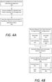
- FIGS. 4A and 4B are a flow chart describing example methods of configuring a PLADAR system, as described herein.
- the methods described with respect to FIGS. 4A and 4B may be performed by an example PLADAR controller 150, 235 shown and described with respect to FIGS. 1 and 2 .
- the PLADAR controller 150 can receive feedback 132 from the data processor 130 indicating a misalignment (400).
- the feedback 132 identifies the specific misalignment (e.g., leftward, rightward, topward, downward, clockwise or counterclockwise diagonal misalignments or any combination of the foregoing).
- the feedback 132 can include samplings of the PLADAR data 129, which the PLADAR controller 150 can analyze to identify a data pattern that describes or details the misalignment (405).
- data from the photodetector array 119 can indicate a consistent pattern of bad or unreliable data from any number of individual detectors in the array 119.
- the PLADAR controller 150 can perform an initial set of adjustments on the adjustable components 123 to diagnose the misalignment. In other situations, the misalignment may be readily identified by the PLADAR controller 150, and the calibration can be made directly.
- the PLADAR controller 150 can generate and execute adjustment commands 237 on the adjustable components 123 of the photodetector array 119 to realign or re-calibrate the photodetector array 119 to the beam plane 118 (410).
- the PLADAR controller 150 can receive a request from the data processor 130 to adjust PLADAR system 100 configurations (450). For example, based on changing situational conditions (e.g., changing weather such as rain or snow, changing speed, changing environmental complexity or potential hazard count, etc.), the data processor 130 can determine that an increased or decreased pulse rate (451) and/or scan rate (452) is preferable. Additionally or alternatively, the data processor 130 may determine that conditions require an increase in laser intensity (453) to enhance reflectance, or an increase in detector sensitivity (454). Alternatively, the data processor 130 may determine that conditions are conducive to power savings (e.g., in low speed uncrowded situations), and may request to decrease such configurations.
- changing situational conditions e.g., changing weather such as rain or snow, changing speed, changing environmental complexity or potential hazard count, etc.
- the data processor 130 can determine that an increased or decreased pulse rate (451) and/or scan rate (452) is preferable. Additionally or alternatively, the data processor 130 may determine that conditions require an increase in
- the PLADAR controller 150 can generate adjustment commands 237 based on the requests from the data processor 130 (455). The PLADAR controller 150 can then execute the adjustment commands 237 on the relevant components of the PLADAR system 100 to configure the PLADAR system 100 accordingly (460). For example, the PLADAR controller 150 can execute commands 237 on the PLADAR motor 120 to increase or decrease the scan rate (461). As another example, the PLADAR controller 150 can execute commands 237 on the timing component 135 to increase or decrease a pulse rate of the laser (462). Further, the PLADAR controller 150 can execute commands 237 on the laser source itself to increase or decrease laser intensity (e.g., increase or decrease power or beam frequency) (463). Still further, in some implementations, the PLADAR controller 150 can execute commands 237 on the detector array 119 to increase or decrease detector sensitivity (464).
- the PLADAR controller 150 can execute commands 237 on the detector array 119 to increase or decrease detector sensitivity (464).
- data processor 130 and PLADAR controller 150 are shown as separate components in FIGS. 1 and 2 , it is contemplated that certain embodiments can include a single component (e.g., one or more blade computers of an autonomous vehicle 200 that perform all of the operations described with respect to FIG. 3 and FIGS. 4A and 4B .
- FIG. 5 is a block diagram that illustrates a computer system upon which examples described herein may be implemented.
- a computer system 500 can be implemented on, for example, a server or combination of servers.
- the computer system 500 may be implemented as part of a data processing system 130, which itself may be implemented as a part of the AV's on-board data processing system 210.
- the data processing system 130 may be implemented with the PLADAR controller 150 as a single computer system 500, or using a combination of multiple computer systems as described in connection with FIG. 5 .
- the computer system 500 includes processing resources 510, a main memory 520, a read-only memory (ROM) 530, a storage device 540, and a communication interface 550.
- the computer system 500 includes at least one processor 510 for processing information stored in the main memory 520, such as provided by a random access memory (RAM) or other dynamic storage device, for storing information and instructions which are executable by the processor 510.
- the main memory 520 also may be used for storing temporary variables or other intermediate information during execution of instructions to be executed by the processor 510.
- the computer system 500 may also include the ROM 530 or other static storage device for storing static information and instructions for the processor 510.
- a storage device 540 such as a magnetic disk or optical disk, is provided for storing information and instructions.
- the communication interface 550 enables the computer system 500 to communicate with the PLADAR system 580 over a network link (e.g., a wireless or wired link).
- the computer system 500 receives PLADAR data 582 from the PLADAR system 580.
- the executable instructions stored in the memory 530 can include configuration instructions 522, which the processor 510 executes to generate a set of adjustment commands 554 to configure the adjustable parameters of the autonomous vehicle's PLADAR system 580 based on the PLADAR data 582 and the situational conditions of the autonomous vehicle 200.
- the processor 510 is configured with software and/or other logic to perform one or more processes, steps and other functions described with implementations, such as described by FIGS. 1 through 4B , and elsewhere in the present application.
- Examples described herein are related to the use of the computer system 500 for implementing the techniques described herein. According to one example, those techniques are performed by the computer system 500 in response to the processor 510 executing one or more sequences of one or more instructions contained in the main memory 520. Such instructions may be read into the main memory 520 from another machine-readable medium, such as the storage device 540. Execution of the sequences of instructions contained in the main memory 520 causes the processor 510 to perform the process steps described herein. In alternative implementations, hard-wired circuitry may be used in place of or in combination with software instructions to implement examples described herein. Thus, the examples described are not limited to any specific combination of hardware circuitry and software.
Abstract
Description
- This application claims the benefit of priority to
U.S. Application No. 15/446,953, entitled "PLANAR-BEAM, LIGHT DETECTION AND RANGING SYSTEM," and filed on March 1, 2017 U.S. Provisional Application No. 62/303,013, entitled "PLANAR-BEAM, LIGHT DETECTION AND RANGING SYSTEM," and filed on March 3, 2016 - Light detection, and ranging (LIDAR or LADAR) systems utilize a number of laser beams to detect reflectance or backscatter from the laser beams to map surface features or for remote sensing. For typical LIDAR systems, each beam is precisely configured with a dedicated photodetector that detects the reflectance and/or backscatter from that particular beam. As the beam count increases, so do cost and space requirements for the individual lasers and photodetectors.
- The disclosure herein is illustrated by way of example, and not by way of limitation, in the figures of the accompanying drawings in which like reference numerals refer to similar elements, and in which:
-
FIG. 1 is a diagram illustrating an example planar-beam, light detection and ranging (PLADAR) system, as described herein; -
FIG. 2 is a block diagram illustrating an example autonomous vehicle (AV) including a PLADAR system, as described herein; -
FIG. 3 is a flow chart describing an example method of processing PLADAR data, according to one or more examples described herein; -
FIGS. 4A and 4B are a flow chart describing example methods of configuring a PLADAR system, as described herein; and -
FIG. 5 is a block diagram illustrating an example computing system upon which examples described herein may be implemented. - Current LIDAR technology involves fixed-beam LIDAR systems that include laser sources, scanners, optical systems (e.g., beam splitters and/or collimators), and photodetectors. For example, cutting edge LIDAR systems can include pulse rates on the order of one million pulses per second producing a detailed point cloud map of an autonomous vehicle's surroundings at ranges upwards of one hundred-plus meters. These LIDAR systems require precision pulse sequencing for the laser beams for multiple reasons, such as power constraints, sampling and/or processing constraints, and the like. When using typical LIDAR systems for autonomous vehicles traveling on public roads, operational speed may be limited by the nature of the beam pattern produced by the LIDAR system. For example, in order to ensure safety for an autonomous vehicle traveling at low speeds over public roads, a LIDAR system may require several separate beams to readily detect potential hazards with sufficient granularity to decelerate, maneuver, and/or stop the autonomous vehicle accordingly. When the autonomous vehicle travels at high speeds (e.g., 60 mph, 75 mph, etc.), in order to achieve the same granularity for potential hazards in order to safely react, decelerate, and/or stop the autonomous vehicle, a fixed-beam LIDAR system may require well over seventy separate beams.
- Increasing the number of fixed beams places additional requirements for a LIDAR system. For example, the LIDAR system will require more power, greater processing capability, larger or more sensitive photodetector and receiving equipment, constrained optics, and generally greater weight and more space. Furthermore, cost and waste quickly become an issue when increasing the number of fixed-beams, since the beam pattern for the fixed-beam LIDAR system must be tuned for a maximum operational speed of the autonomous vehicle. If autonomous vehicles are to operate safely with LIDAR technology on public highways at high speed, then alternative arrangements may be necessary to avoid spiraling costs, wasted power, additional equipment, and increased processing requirements.
- To address many of the shortcomings of fixed-beam LIDAR systems, a planar-beam, light detection and ranging (PLADAR) system is provided. The PLADAR system can include a laser scanner that emits a planar-beam, and a detector array to detect reflected light (e.g., backscatter) from the planar beam. In some aspects, the laser scanner can include a collimation component that collimates a laser beam generated by the laser scanner into the planar beam. The laser scanner can utilize a single laser collimated on an axis (e.g., a vertical axis) to generate the planar beam, which can extend from the laser scanner approximately triangularly as opposed to linearly. According to certain implementations, the laser scanner can include a fiber laser that generates the laser beam for axial collimation. Fiber lasers can offer vibrational stability, ideal optical quality, and compact size in addition to other desirable qualities. However, virtually any type of laser with appropriate emission characteristics may be used, such as certain types of gas lasers, excimer lasers, dye lasers, other forms of solid state lasers, semi-conductor based lasers, metal vapor lasers, etc. utilizing continuous wave or pulsed emissions. For autonomous vehicle applications, wavelengths on the order of 1000 nanometers (nm) (e.g., 1200-1550 nm) corresponding to the near-infrared spectral range may be optimal for health and safety reasons.
- In many examples, the detector array of the PLADAR system can include at least one set of photodetectors, such as one or more linear rows of photodetectors, which can be included on a circuit board of the PLADAR system. The circuit board can include a number of adjustment components for the photodetector array(s) to calibrate the photodetectors in concert. In some aspects, the PLADAR system can further include an adjustment controller to dynamically adjust the adjustment components to optimally configure the row(s) of photodetectors in response to a command signal. The command signal may be generated by a calibration system pre-implementation, or dynamically when the PLADAR system is in use. Additionally or alternatively, the adjustment components can be tuned manually by a user or technician when calibrating the photodetector array to the planar beam.
- Accordingly to examples described herein, the PLADAR system can be implemented on an autonomous vehicle to provide sensor data to an on-board data processing system of the autonomous vehicle. The PLADAR system can include an analog-to-digital converter (ADC) chain coupled to the photodetector array. In certain implementations, the ADC chain can generate output from all of the photodetectors simultaneously, and the outputted data can be processed (e.g., by the on-board data processing system of the autonomous vehicle) accordingly. In such implementations, the pulse rate of the planar beam can be significantly reduced compared to fixed-beam LIDAR systems. For example, when fine granularity is desired, instead of transmitting one hundred or so beams (e.g., with ~0.15° beam spacing), examples described herein can transmit a single (or multiple) beam planes with the same or similar data quality at ~1/100th the pulse rate.
- Among other benefits, the examples described herein achieve a technical effect of providing an alternative to increasingly expensive, complex, and tediously calibrated LIDAR systems. A PLADAR system can maintain or increase data quality while reducing cost and complexity, which are increasing concerns in autonomous vehicle technology and currently function as hindrances in the rollout of autonomous vehicles for common use.
- As used herein, a PLADAR system implements remote sensing using planar beams as opposed to linear beams. "PLADAR" is used herein to represent any light detection and ranging system that uses two-dimensional beam planes for remote sensing.
- As used herein, a computing device refer to devices corresponding to desktop computers, cellular devices or smartphones, personal digital assistants (PDAs), field programmable gate arrays (FPGAs), laptop computers, tablet devices, television (IP Television), etc., that can provide network connectivity and processing resources for communicating with the system over a network. A computing device can also correspond to custom hardware, in-vehicle devices, or on-board computers, etc. The computing device can also operate a designated application configured to communicate with the network service.
- One or more examples described herein provide that methods, techniques, and actions performed by a computing device are performed programmatically, or as a computer-implemented method. Programmatically, as used herein, means through the use of code or computer-executable instructions. These instructions can be stored in one or more memory resources of the computing device. A programmatically performed step may or may not be automatic.
- One or more examples described herein can be implemented using programmatic modules, engines, or components. A programmatic module, engine, or component can include a program, a sub-routine, a portion of a program, or a software component or a hardware component capable of performing one or more stated tasks or functions. As used herein, a module or component can exist on a hardware component independently of other modules or components. Alternatively, a module or component can be a shared element or process of other modules, programs or machines.
- Some examples described herein can generally require the use of computing devices, including processing and memory resources. For example, one or more examples described herein may be implemented, in whole or in part, on computing devices such as servers, desktop computers, cellular or smartphones, personal digital assistants (e.g., PDAs), laptop computers, printers, digital picture frames, network equipment (e.g., routers) and tablet devices. Memory, processing, and network resources may all be used in connection with the establishment, use, or performance of any example described herein (including with the performance of any method or with the implementation of any system).
- Furthermore, one or more examples described herein may be implemented through the use of instructions that are executable by one or more processors. These instructions may be carried on a computer-readable medium. Machines shown or described with figures below provide examples of processing resources and computer-readable mediums on which instructions for implementing examples disclosed herein can be carried and/or executed. In particular, the numerous machines shown with examples of the invention include processor(s) and various forms of memory for holding data and instructions. Examples of computer-readable mediums include permanent memory storage devices, such as hard drives on personal computers or servers. Other examples of computer storage mediums include portable storage units, such as CD or DVD units, flash memory (such as carried on smartphones, multifunctional devices or tablets), and magnetic memory. Computers, terminals, network enabled devices (e.g., mobile devices, such as cell phones) are all examples of machines and devices that utilize processors, memory, and instructions stored on computer-readable mediums. Additionally, examples may be implemented in the form of computer-programs, or a computer usable carrier medium capable of carrying such a program.
-
FIG. 1 is a block diagram illustrating an example planar-beam, light detection and ranging (PLADAR) system, as described herein. The PLADAR system 100 can include a PLADAR scanner and optics 114 that generate a two-dimensional beam plane 118. The scanner/optics 114 can include a single laser source (or multiple laser sources) that generates a laser beam. In certain aspects, the laser source of thebeam plane 118 can be a fiber laser emitting in the near to mid infrared spectral range. The optics of the scanner/optics 114 can include a number mirrors and/or a collimation component that collimates the laser beam axially to form thebeam plane 118. The collimation component can include a number of lenses, spatial filters, mirrors, fiber optics, and/or gratings, which can filter, amplify, and/or narrow a resultantplanar beam 118. Accordingly, the collimation component of the scanner/optics 114 collimates the laser beam on a single axis to generate thebeam plane 118. - In many aspects, the PLADAR system 100 can include a
photodetector array 119 including a number of individual photodetectors. According to examples described herein, thephotodetector array 119 can comprise a linear arrangement (e.g., as a one or more linear rows of photodetectors) to correlate with thebeam plane 118 emitted by the PLADAR system 100. For example, the individual photodetectors can be included and calibrated on a circuit board to be aligned with thebeam plane 118. Furthermore, thephotodetector array 119 can include a number of adjustable components 123 (e.g., calibration screws) that can allow for straightforward calibration of thephotodetector array 119 with thebeam plane 118. In some aspects, thephotodetector array 119 can include a sufficient number of individual photodetectors (e.g., tens to hundreds) for generating sensor data with sufficient granularity to detect any possible road hazards (e.g., objects with size on the order of feet or inches) for operating an autonomous vehicle on public roads. In such aspects, thephotodetector array 119 can include as many or more photodetectors as current or future state of the art fixed-beam LIDAR systems. - In various implementations, the
photodetector array 119 can include multiple linear arrangements of photodetectors, and/or interleaved detectors across the multiple linear arrangements. For example, thephotodetector array 119 can include two or more lines of photodetectors to take advantage of the beam spread of thebeam plane 118. In variations, the nature of thebeam plane 118 can allow for any suitable arrangement for thephotodetector array 119, such as separate staggered photodetector lines of varying lengths, a wider central arrangement, a narrower central arrangement, and the like. Thus, in addition to a single linear row of photodetectors, the photodetector array can include a plurality of photodetector rows aligned in a manner corresponding to thebeam plane 118. - The
photodetector array 119 detects reflection and/orbackscatter 126 from thebeam plane 118, and atiming component 135 is utilized to perform ranging operations for the PLADAR system 100. Accordingly, the PLADAR system 100 actively transmits thebeam plane 118, light from thebeam plane 118 is reflected off objects and surfaces, and this reflection/backscatter 126 is detected by the individual receivers of thephotodetector array 119. Data from the detected light is precisely timed to perform the ranging operations (e.g., dynamic calculations of distance to each surface) and generate a dynamic point cloud map of the situational environment of the PLADAR system 100. - Furthermore, LIDAR systems sequence the individual beams and detectors in order to decrease power and processing loads, which can constrain data quality. The PLADAR system 100 can utilize a
single beam plane 118 at a single pulse rate, which may be increased or decreased accordingly depending on the situational environment (e.g., a crowded city environment, a rural road with little or no traffic, etc.). In certain aspects,PLADAR sensor data 129 from the photodetectors of thephotodetector array 119 may be sampled simultaneously from all photodetectors by a local orexternal data processor 130. Thus, in some implementations, thedata processor 130 can be included as a component of the PLADAR system 100. In other implementations, thedata processor 130 may be remote, and/or can be included as a part of, for example, an on-board data processing system of an autonomous vehicle. - Each detector of the
photodetector array 119 can include an analog-to-digital converter (ADC), which converts the detected light signal from the reflection/backscatter 126 of thebeam plane 118 into a digital signal for processing. Accordingly, in many examples, thephotodetector array 119 can include an ADC chain, similar to certain LIDAR systems. The combined data from the ADC chain (i.e., PLADAR sensor data 129) can be sampled by the data processor 130 (e.g., simultaneously or near-simultaneously for each pulse) to generate the point cloud map of the situational environment.Feedback 132 can be provided by thedata processor 130 to aPLADAR controller 150, or adjustment controller, which can make adjustments to the configurable parameters of the PLADAR system 100. - According to examples described herein, the individual detectors of the
photodetector array 119 can be adjusted in concert using the adjustable components 123. In certain examples, thephotodetector array 119 can be pre-calibrated and aligned with thebeam plane 118 during the manufacturing process. Additionally or alternatively, when a misalignment is detected (e.g., by the data processor 130), thephotodetector array 119 may be manually calibrated during servicing. Additionally or alternatively still, thefeedback 132 provided by thedata processor 130 can indicate the misalignment, and can be processed by thePLADAR controller 150. ThePLADAR controller 150 can determine a number of adjustments based on thefeedback 132, and can utilize the adjustable components 123 to re-calibrate thephotodetector array 119 automatically and on the fly. - In certain aspects, the
PLADAR controller 150 can further operate thePLADAR motor 120, which can, for example, control a rotational rate of the PLADAR system 100. The PLADAR controller can further control thetiming component 135 and the PLADAR scanner/optics 114 to increase or decrease the pulse rate when, for example, finer granularity in the generated point cloud is needed (e.g., in pedestrian rich environments). Generally, however, the pulse rate of thebeam plane 118 can be far less (e.g., 100x less) than those of typical LIDAR systems, since the PLADAR system 100 utilizes a single light source. - Other arrangements are contemplated. For example, the PLADAR scanner/optics 114 can generate the
beam plane 118 along with one or more linear beams having dedicated detectors. As another example, the PLADAR scanner/optics 114 can generate multiple beam planes 118. The embodiment illustrated inFIG. 1 shows a rotational PLADAR system 100 operated by aPLADAR motor 120. However, example PLADAR systems 100 described herein can include a scanning motor that uses abeam plane 118 to scan a certain directional aspect (e.g., directly in front of an autonomous vehicle). Further, thebeam plane 118 is axially collimated on a single axis, and can be collimated vertically, horizontally, in a slanted manner (as shown), and can provide almost any desired vertical field of view (e.g., a 45° VFOV at 25 meters). -
FIG. 2 is a block diagram illustrating an example autonomous vehicle including a PLADAR system, as described herein. ThePLADAR system 205 of the autonomous vehicle (AV) 200 can providePLADAR data 202 to an on-boarddata processing system 210 of theautonomous vehicle 200. In some examples, thePLADAR system 205 can comprise a light source (e.g., a laser), a photodetector, scanner components (e.g., which can include one or more lens(es), mirror(s), motor(s), actuator(s), etc.), and circuitry to couple to various components of theautonomous vehicle 200. Thedata processing system 210 can utilize thePLADAR data 202 to detect the situational conditions of theautonomous vehicle 200 as the AV 100 travels along a current route. For example, thedata processing system 210 can identify potential obstacles or road hazards-such as pedestrians, bicyclists, objects on the road, road cones, road signs, animals, etc.-in order to enable anAV control system 220 to react accordingly. - In certain implementations, the
data processing system 210 can utilize sub-maps 233 stored in adatabase 230 of theautonomous vehicle 200 in order to perform localization and pose operations to determine a current location and orientation of theautonomous vehicle 200 in relation to a given region (e.g., a city). The sub-maps 233 can comprise previously recorded sensor data, such as stereo camera data, radar maps, and/or point cloud LIDAR maps that enable thedata processing system 210 to compare thePLADAR data 202 from thePLADAR system 205 with acurrent sub-map 234 to identify such obstacles and potential road hazards in real time. Thedata processing system 210 can provide the processed sensor data 213-identifying such obstacles and road hazards-toAV control system 220, which can react accordingly by operating the steering, braking, andacceleration systems 225 of theautonomous vehicle 200. - In some examples, the
autonomous vehicle 200 further includes a number ofstereo cameras 260 that generatedynamic image data 262 of the autonomous vehicle's 200 surroundings. For example, theautonomous vehicle 200 can includestereo cameras 260 with fields of view showing a 360° panorama (or forward and rearward directions) of theautonomous vehicle 200. The on-boarddata processing system 210 can further process thedynamic image data 262 to identify features or potential hazards along the current route traveled. The processeddata 213 can include processed image data from thestereo cameras 260, which can be utilized by theAV control system 220 to perform low level maneuvering. - In many implementations, the
AV control system 220 can receive adestination 219 from, for example, aninterface system 215 of theautonomous vehicle 200. Theinterface system 215 can include any number of touch-screens, voice sensors, mapping resources, etc. that enable apassenger 239 to provide apassenger input 241 indicating thedestination 219. For example, thepassenger 239 can type thedestination 219 into amapping engine 275 of theautonomous vehicle 200, or can speak thedestination 219 into theinterface system 215. Additionally or alternatively, theinterface system 215 can include a wireless communication module that can connect theautonomous vehicle 200 to anetwork 280 to communicate with a backendtransport arrangement system 290 to receiveinvitations 282 to service a pick-up or drop-off request.Such invitations 282 can include destination 219 (e.g., a pick-up location), and can be received by theautonomous vehicle 200 as a communication over thenetwork 280 from the backendtransport arrangement system 290. In many aspects, the backendtransport arrangement system 290 can manage routes and/or facilitate transportation for users using a fleet of autonomous vehicles throughout a given region. The backendtransport arrangement system 290 can be operative to facilitate passenger pick-ups and drop-offs to generally service pick-up requests, facilitate delivery such as packages, food, or animals, and the like. - Based on the destination 219 (e.g., a pick-up location), the
AV control system 220 can utilize themapping engine 275 to receiveroute data 232 indicating a route to thedestination 219. In variations, themapping engine 275 can also generatemap content 226 dynamically indicating the route traveled to thedestination 219. Theroute data 232 and/ormap content 226 can be utilized by theAV control system 220 to maneuver theautonomous vehicle 200 to thedestination 219 along the selected route. For example, theAV control system 220 can dynamically generate control commands 221 for the autonomous vehicle's steering, braking, andacceleration system 225 to actively drive theautonomous vehicle 200 to thedestination 219 along the selected route. Optionally, themap content 226 showing the current route traveled can be streamed to theinterior interface system 215 so that the passenger(s) 239 can view the route and route progress in real time. - In many examples, while the
AV control system 220 operates the steering, braking, andacceleration systems 225 along the current route on a high level, and the processeddata 213 provided to theAV control system 220 can indicate low level occurrences, such as obstacles and potential hazards to which theAV control system 220 can make decisions and react. For example, the processeddata 213 can indicate a pedestrian crossing the road, traffic signals, stop signs, other vehicles, road conditions, traffic conditions, bicycle lanes, crosswalks, pedestrian activity (e.g., a crowded adjacent sidewalk), and the like. TheAV control system 220 can respond to the processeddata 213 by generating control commands 221 to reactively operate the steering, braking, andacceleration systems 225 accordingly. - According to examples described herein, the
autonomous vehicle 200 can include aPLADAR controller 235 to receivefeedback data 223 from thedata processing system 210 in order to configure various adjustable parameters of thePLADAR system 205. Thefeedback data 223 can include information indicating data quality, such as errors or uncertainty in the data from certain individual photodetectors, which can be extrapolated by thePLADAR controller 235 to determine a number of adjustment commands 237 for thePLADAR system 205 that can correct the error(s). For example, thePLADAR controller 235 can identify a pattern in thefeedback data 223 indicating a misalignment of the photodetector array with respect to the PLADAR beam 207. ThePLADAR controller 235 can identify the misalignment and generate the adjustment commands 237 for execution on the adjustable components of the photodetector array to re-calibrate thePLADAR system 205. As discussed herein, the adjustment commands 237 can be executed on the adjustable components dynamically as theautonomous vehicle 200 travels along a current route, or during garage servicing of theautonomous vehicle 200. - Additionally or alternatively, the
feedback data 223 can include requests from thedata processing system 210 for thePLADAR controller 235 to configure thePLADAR system 205 for increased or decreased granularity. For example, thedata processing system 210 can identify a substantial decrease in potential hazards (e.g., when theautonomous vehicle 200 leaves a city and enters open rural road with little traffic). Thefeedback data 223 can include a request to save power in such conditions by decreasing the pulse rate and/or scan rate of thePLADAR system 205. Accordingly, in some aspects, the adjustment commands 237 can be generated by thePLADAR controller 235 to adjust a rotational parameter 209 (e.g., decrease a rotational rate) and/or decrease the pulse rate of the PLADAR beam 207-thereby enabling a decrease in sample rate by thedata processing system 210. - Conversely, the on-board
data processing system 210 can identify an increase in potential hazards (e.g., entering an area of increased pedestrian activity) or an increased probability of experiencing hazards (e.g., when traveling at high speeds), and request that thePLADAR controller 235 generate adjustment commands 237 to increase the sample rate.Such commands 237 can be executed on the adjustable parameters of thePLADAR system 205 to increase a pulse rate of the PLADAR beam 207 and/or increase the rotational rate-thereby enabling thedata processing system 210 to increase the sample rate and bolster point cloud granularity. -
FIG. 3 is a flow chart describing an example method of processing PLADAR data, according to one or more examples described herein. In the below description ofFIG. 3 , reference may be made to like features represented by reference characters fromFIGS. 1 and2 . Furthermore, the method described with respect toFIG. 3 may be performed by anexample data processor 130 shown and described with respect toFIG. 1 , or an on-boarddata processing system 230 shown and described with respect toFIG. 2 . Referring toFIG. 3 , thedata processor 130 can sample data from each detector of the PLADAR system 100 simultaneously (300). For example, thedata processor 130 can monitor each ADC of an ADC chain coupled to thephotodetector array 119. For eachbeam plane 118 pulse, return light signals (e.g., reflection/backscatter 126) can be received by thephotodetector array 119. Each detector can include an ADC that converts the detected light signal into a digital signal, and atiming component 135 can be utilized by thedata processor 130 to precisely perform ranging for each ADC of the ADC chain and for everybeam plane 118 pulse. - The data processor 130 (e.g., of an autonomous vehicle 200) can process the
PLADAR data 129 to perform ranging and identify potential hazards (305). For example, thedata processor 130 can be programmed to identify aspects of the autonomous vehicle's situational environment that causes theautonomous vehicle 200 to operate safely on public roads. Such aspects can include pedestrians, bicyclists, hazardous objects on the road (e.g., rocks), stop lights, signs, other vehicles, and the like. Theprocessor 130 can identify such aspects by, for example, comparing thePLADAR data 129 to a stored sub-map including prerecorded data on the same current route, as described with respect toFIG. 2 . In many implementations, thedata processor 130 transmits the processedsensor data 213 to anAV control system 220, which can control the autonomous vehicle's 200 steering braking, andacceleration systems 225 to make decisions and react to each processed object for low level maneuvering (310). Additionally, theAV control system 220 can further utilizedynamic image data 262 from astereo camera system 260 of theautonomous vehicle 200 for low level maneuvering. - In certain implementations, the
data processor 130 can identify, in thePLADAR data 129, a misalignment between thephotodetector array 119 and the beam plane 118 (315). As an example, thePLADAR data 129 can indicate unreliable data for the top detectors and the bottom detectors, which can indicate a diagonal misalignment of thephotodetector array 118. In some aspects, thedata processor 130 can determine the nature of the misalignment based on the sampledPLADAR data 129. In other aspects, thedata processor 130 can generally identify the error in the data, and generatefeedback 132 requesting thePLADAR controller 150 to perform a diagnostics test. In either aspect, thedata processor 130 can generatefeedback 132 indicating the misalignment (320), and transmit the feedback to thePLADAR controller 150 to re-calibrate thephotodetector array 119 to the planar beam 118 (325). - According to some examples, the
data processor 130 can determine a condition change in the situational environment of the autonomous vehicle 200 (330). As an example, thedata processor 130 can identify that theautonomous vehicle 200 is traveling at higher speeds, and that more detailed data from a forward direction of theautonomous vehicle 200 is desired. Thedata processor 130 can generate a request to adjust the PLADAR system 100 configurations to, for example, increase a pulse rate, scan rate, detector sensitivity, and/or a laser intensity to increase the data quality (335). Conversely, to optimize power and processing resources, in certain circumstances (e.g., low speed operation), thedata processor 130 can generate a request to decrease such configurable parameters when situational conditions are conducive to such decreases (335). These requests can be transmitted to the PLADAR controller 150 (340), which can execute adjustment commands 237 on the configurable components of the PLADAR system 100 accordingly. -
FIGS. 4A and 4B are a flow chart describing example methods of configuring a PLADAR system, as described herein. In the below description ofFIGS. 4A and 4B , reference may be made to like features represented by reference characters fromFIGS. 1 and2 . Furthermore, the methods described with respect toFIGS. 4A and 4B may be performed by anexample PLADAR controller FIGS. 1 and2 . Referring toFIG. 4A , thePLADAR controller 150 can receivefeedback 132 from thedata processor 130 indicating a misalignment (400). In some examples, thefeedback 132 identifies the specific misalignment (e.g., leftward, rightward, topward, downward, clockwise or counterclockwise diagonal misalignments or any combination of the foregoing). - In other examples, the
feedback 132 can include samplings of thePLADAR data 129, which thePLADAR controller 150 can analyze to identify a data pattern that describes or details the misalignment (405). For example, data from thephotodetector array 119 can indicate a consistent pattern of bad or unreliable data from any number of individual detectors in thearray 119. In some situations, thePLADAR controller 150 can perform an initial set of adjustments on the adjustable components 123 to diagnose the misalignment. In other situations, the misalignment may be readily identified by thePLADAR controller 150, and the calibration can be made directly. Accordingly, once the precise misalignment is identified, thePLADAR controller 150 can generate and execute adjustment commands 237 on the adjustable components 123 of thephotodetector array 119 to realign or re-calibrate thephotodetector array 119 to the beam plane 118 (410). - Referring to
FIG. 4B , thePLADAR controller 150 can receive a request from thedata processor 130 to adjust PLADAR system 100 configurations (450). For example, based on changing situational conditions (e.g., changing weather such as rain or snow, changing speed, changing environmental complexity or potential hazard count, etc.), thedata processor 130 can determine that an increased or decreased pulse rate (451) and/or scan rate (452) is preferable. Additionally or alternatively, thedata processor 130 may determine that conditions require an increase in laser intensity (453) to enhance reflectance, or an increase in detector sensitivity (454). Alternatively, thedata processor 130 may determine that conditions are conducive to power savings (e.g., in low speed uncrowded situations), and may request to decrease such configurations. - In any case, the
PLADAR controller 150 can generate adjustment commands 237 based on the requests from the data processor 130 (455). ThePLADAR controller 150 can then execute the adjustment commands 237 on the relevant components of the PLADAR system 100 to configure the PLADAR system 100 accordingly (460). For example, thePLADAR controller 150 can executecommands 237 on thePLADAR motor 120 to increase or decrease the scan rate (461). As another example, thePLADAR controller 150 can executecommands 237 on thetiming component 135 to increase or decrease a pulse rate of the laser (462). Further, thePLADAR controller 150 can executecommands 237 on the laser source itself to increase or decrease laser intensity (e.g., increase or decrease power or beam frequency) (463). Still further, in some implementations, thePLADAR controller 150 can executecommands 237 on thedetector array 119 to increase or decrease detector sensitivity (464). - While the
data processor 130 andPLADAR controller 150 are shown as separate components inFIGS. 1 and2 , it is contemplated that certain embodiments can include a single component (e.g., one or more blade computers of anautonomous vehicle 200 that perform all of the operations described with respect toFIG. 3 andFIGS. 4A and 4B . -
FIG. 5 is a block diagram that illustrates a computer system upon which examples described herein may be implemented. Acomputer system 500 can be implemented on, for example, a server or combination of servers. For example, thecomputer system 500 may be implemented as part of adata processing system 130, which itself may be implemented as a part of the AV's on-boarddata processing system 210. In the context ofFIG. 1 , thedata processing system 130 may be implemented with thePLADAR controller 150 as asingle computer system 500, or using a combination of multiple computer systems as described in connection withFIG. 5 . - In one implementation, the
computer system 500 includes processingresources 510, amain memory 520, a read-only memory (ROM) 530, astorage device 540, and acommunication interface 550. Thecomputer system 500 includes at least oneprocessor 510 for processing information stored in themain memory 520, such as provided by a random access memory (RAM) or other dynamic storage device, for storing information and instructions which are executable by theprocessor 510. Themain memory 520 also may be used for storing temporary variables or other intermediate information during execution of instructions to be executed by theprocessor 510. Thecomputer system 500 may also include theROM 530 or other static storage device for storing static information and instructions for theprocessor 510. Astorage device 540, such as a magnetic disk or optical disk, is provided for storing information and instructions. - The
communication interface 550 enables thecomputer system 500 to communicate with thePLADAR system 580 over a network link (e.g., a wireless or wired link). In accordance with examples, thecomputer system 500 receivesPLADAR data 582 from thePLADAR system 580. The executable instructions stored in thememory 530 can includeconfiguration instructions 522, which theprocessor 510 executes to generate a set of adjustment commands 554 to configure the adjustable parameters of the autonomous vehicle'sPLADAR system 580 based on thePLADAR data 582 and the situational conditions of theautonomous vehicle 200. - The
processor 510 is configured with software and/or other logic to perform one or more processes, steps and other functions described with implementations, such as described byFIGS. 1 through 4B , and elsewhere in the present application. - Examples described herein are related to the use of the
computer system 500 for implementing the techniques described herein. According to one example, those techniques are performed by thecomputer system 500 in response to theprocessor 510 executing one or more sequences of one or more instructions contained in themain memory 520. Such instructions may be read into themain memory 520 from another machine-readable medium, such as thestorage device 540. Execution of the sequences of instructions contained in themain memory 520 causes theprocessor 510 to perform the process steps described herein. In alternative implementations, hard-wired circuitry may be used in place of or in combination with software instructions to implement examples described herein. Thus, the examples described are not limited to any specific combination of hardware circuitry and software. - It is contemplated for examples described herein to extend to individual elements and concepts described herein, independently of other concepts, ideas or system, as well as for examples to include combinations of elements recited anywhere in this application. Although examples are described in detail herein with reference to the accompanying drawings, it is to be understood that the concepts are not limited to those precise examples. As such, many modifications and variations will be apparent to practitioners skilled in this art. Accordingly, it is intended that the scope of the concepts be defined by the following claims and their equivalents. Furthermore, it is contemplated that a particular feature described either individually or as part of an example can be combined with other individually described features, or parts of other examples, even if the other features and examples make no mentioned of the particular feature. Thus, the absence of describing combinations should not preclude claiming rights to such combinations.
- Although the present invention is defined in the attached claims, it should be understood that the present invention can also (alternatively) be defined in accordance with the following embodiments:
- 1. A planar-beam, light detection and ranging (PLADAR) system, the PLADAR system comprising :
- a laser scanner emitting a planar-beam; and
- a detector array to detect reflected light from the planar beam.
- 2. The PLADAR system of embodiment 1, wherein the laser scanner comprises a collimation component that collimates a laser beam generated by the laser scanner into the planar beam.
- 3. The PLADAR system of embodiment 2, wherein the laser scanner comprises a fiber laser that outputs the laser beam.
- 4. The PLADAR system of embodiment 1, wherein the detector array comprises at least one row of photodetectors.
- 5. The PLADAR system of embodiment 4, wherein the at least one row of photodetectors are included on a circuit board of the PLADAR system, the circuit board comprising a number of adjustment components to calibrate each of the at least one row of photodetectors in concert.
- 6. The PLADAR system of embodiment 5, further comprising :
an adjustment controller to dynamically adjust the adjustment components to configure the at least one row of photodetectors in response to a command signal from a data processing system. - 7. The PLADAR system of embodiment 6, wherein the PLADAR system is included on an autonomous vehicle (AV), and wherein the data processing system processes sensor data from the PLADAR system to dynamically identify features as the AV accelerates and maneuvers.
- 8. The PLADAR system of embodiment 6, further comprising :
an analog to digital converter (ADC) chain coupled to the at least one row of photodetectors; wherein the data processing system samples data from each ADC of the ADC chain simultaneously. - 9. An autonomous vehicle (AV) comprising :
- at least one planar-beam, light detection and ranging (PLADAR) system to generate sensor data indicating a situational environment of the AV, each of the at least one PLADAR system comprising (i) a laser scanner emitting a planar beam, and (ii) a detector array to detect reflected light from the planar beam;
- an on-board data processing system to process the sensor data from the PLADAR system to identify features along a current route traveled by the AV;
- an acceleration, braking, and steering system; and
- an AV control system to utilize the processed sensor data to operate the acceleration, braking, and steering system along the current route.
- 10. The AV of embodiment 9, wherein the laser scanner comprises a collimation component that collimates a laser beam generated by the laser scanner into the planar beam.
- 11. The AV of embodiment 10, wherein the laser scanner comprises a fiber laser that outputs the laser beam.
- 12. The AV of embodiment 9, wherein the detector array comprises at least one row of photodetectors.
- 13. The AV of embodiment 12, wherein the at least one row of
photodetectors are included on a circuit board of the PLADAR system, the circuit board comprising a number of adjustment components to calibrate each of the at least one row of photodetectors in concert. - 14. The AV of embodiment 13, wherein the PLADAR system further includes an adjustment controller to dynamically adjust the adjustment components to configure the at least one row of photodetectors in response to a command signal from the on-board data processing system.
- 15. The AV of embodiment 12, wherein the PLADAR system further include an analog to digital converter (ADC) chain coupled to the at least one row of photodetectors, and wherein the on-board data processing system processes data from each ADC of the ADC chain simultaneously.
- 16. The AV of embodiment 12, further comprising :
- a stereo camera system to generate dynamic image data further indicating the situational environment of the AV;
- wherein the on-board data processing system further processes the dynamic image data to further identify features along the current route traveled by the AV.
- 17. The AV of embodiment 16, wherein the AV control system further utilizes the processed dynamic image data to operate the acceleration, braking, and steering system along the current route.
- 18. The AV of embodiment 17, further comprising :
- a communication interface to receive commands from a backend transport system that facilitates transportation for a number of users throughout a given region, each respective one of the commands including a destination;
- wherein the AV control system processes the respective command to operate the acceleration, braking, and steering system to drive the AV to the destination.
- 19. The AV of embodiment 18, wherein the AV control system utilizes an on-board mapping resource to determine an optimal route to the destination.
- 20. The AV of embodiment 19, wherein the AV control system simultaneously operates the acceleration, braking, and steering system by (i) utilizing route data, corresponding to the optimal route to the destination, to drive the AV to the destination, and (ii) utilizing the processed sensor data and the processed image data to make decisions and react to the situational environment of the AV.
Claims (14)
- A light detection and ranging (LIDAR) system comprising:a laser configured to output a first laser beam;a collimator configured to collimate the first laser beam on an axis to emit a second laser beam along a beam plane; anda detector array configured to detect return light from the second laser beam, the return light reflecting off objects, the detector array comprising a plurality of photodetectors arranged on a circuit board; andone or more processors configured to:obtain data indicative of the return light from one or more of the photodetectors;determine a misalignment between the beam plane and one or more of the photodetectors based, at least in part, on the data; andgenerate one or more calibration parameters based on the misalignment, the one or more calibration parameters associated with adjusting a position of at least one of the photodetectors.
- The LIDAR system of claim 1, wherein the laser comprises a fiber laser that outputs the first laser beam.
- The LIDAR system of any preceding claim, wherein the collimator comprises a set of mirrors that produce the second laser beam from the first laser beam.
- The LIDAR system of any preceding claim, wherein the collimator comprises a set of lenses that produce the second laser beam from the first laser beam.
- The LIDAR system of any preceding claim, wherein the plurality of photodetectors include at least one row of photodetectors
- The LIDAR system of claim 5, further comprising:
an analog to digital converter (ADC) chain coupled to the at least one row of photodetectors. - The LIDAR system of claim 6, wherein the one or more processors are configured to sample data from each ADC of the ADC chain simultaneously to obtain the data indicative of the return light.
- The LIDAR system of any preceding claim, further comprising:
a plurality of adjustment components disposed on the circuit board, the plurality of adjustment components configured to adjust the position of one or more of the photodetectors. - The LIDAR system of claim 8, wherein the one or more processors are configured to provide a command signal to one or more of the adjustment components, the command signal associated with adjusting the position of the at least one of the photodetectors.
- The LIDAR system of any preceding claim, wherein the beam plane comprises a two dimensional beam plane along which the second laser beam is emitted.
- An autonomous vehicle control system comprising the LIDAR system recited in any of claims 1-10.
- An autonomous vehicle comprising the LIDAR system recited in any of claims 1-10.
- The autonomous vehicle of claim 12 further comprising:acceleration, braking, and steering systems;a control system to autonomously operate the acceleration, braking, and steering systems.
- The autonomous vehicle of claim 12, further comprising:
a control system that processes sensor data from the LIDAR system to dynamically identify features as the autonomous vehicle accelerates and maneuvers.
Applications Claiming Priority (4)
| Application Number | Priority Date | Filing Date | Title |
|---|---|---|---|
| US201662303013P | 2016-03-03 | 2016-03-03 | |
| US15/446,953 US10281923B2 (en) | 2016-03-03 | 2017-03-01 | Planar-beam, light detection and ranging system |
| PCT/US2017/020483 WO2017151943A1 (en) | 2016-03-03 | 2017-03-02 | Planar-beam, light detection and ranging system |
| EP17760835.3A EP3423912B1 (en) | 2016-03-03 | 2017-03-02 | Planar-beam, light detection and ranging system |
Related Parent Applications (1)
| Application Number | Title | Priority Date | Filing Date |
|---|---|---|---|
| EP17760835.3A Division EP3423912B1 (en) | 2016-03-03 | 2017-03-02 | Planar-beam, light detection and ranging system |
Publications (1)
| Publication Number | Publication Date |
|---|---|
| EP3971673A1 true EP3971673A1 (en) | 2022-03-23 |
Family
ID=59722176
Family Applications (2)
| Application Number | Title | Priority Date | Filing Date |
|---|---|---|---|
| EP21208121.0A Pending EP3971673A1 (en) | 2016-03-03 | 2017-03-02 | Planar-beam, light detection and ranging system |
| EP17760835.3A Active EP3423912B1 (en) | 2016-03-03 | 2017-03-02 | Planar-beam, light detection and ranging system |
Family Applications After (1)
| Application Number | Title | Priority Date | Filing Date |
|---|---|---|---|
| EP17760835.3A Active EP3423912B1 (en) | 2016-03-03 | 2017-03-02 | Planar-beam, light detection and ranging system |
Country Status (8)
| Country | Link |
|---|---|
| US (4) | US10281923B2 (en) |
| EP (2) | EP3971673A1 (en) |
| CN (1) | CN109074073B (en) |
| AU (1) | AU2017225790B2 (en) |
| CA (1) | CA3015894C (en) |
| IL (1) | IL261434B (en) |
| SG (1) | SG11201807249YA (en) |
| WO (1) | WO2017151943A1 (en) |
Families Citing this family (22)
| Publication number | Priority date | Publication date | Assignee | Title |
|---|---|---|---|---|
| US10821345B2 (en) | 2014-04-25 | 2020-11-03 | Christopher DeCarlo | Sporting device for analyzing an element in a tunnel, apparatus, system, method, and computer program product |
| US11370422B2 (en) * | 2015-02-12 | 2022-06-28 | Honda Research Institute Europe Gmbh | Method and system in a vehicle for improving prediction results of an advantageous driver assistant system |
| US10338225B2 (en) | 2015-12-15 | 2019-07-02 | Uber Technologies, Inc. | Dynamic LIDAR sensor controller |
| US10281923B2 (en) | 2016-03-03 | 2019-05-07 | Uber Technologies, Inc. | Planar-beam, light detection and ranging system |
| US10234856B2 (en) * | 2016-05-12 | 2019-03-19 | Caterpillar Inc. | System and method for controlling a machine |
| US9952317B2 (en) | 2016-05-27 | 2018-04-24 | Uber Technologies, Inc. | Vehicle sensor calibration system |
| US11889393B2 (en) * | 2017-06-23 | 2024-01-30 | Veniam, Inc. | Methods and systems for detecting anomalies and forecasting optimizations to improve urban living management using networks of autonomous vehicles |
| US10558224B1 (en) * | 2017-08-10 | 2020-02-11 | Zoox, Inc. | Shared vehicle obstacle data |
| US10746858B2 (en) | 2017-08-17 | 2020-08-18 | Uatc, Llc | Calibration for an autonomous vehicle LIDAR module |
| US10775488B2 (en) | 2017-08-17 | 2020-09-15 | Uatc, Llc | Calibration for an autonomous vehicle LIDAR module |
| US11446550B2 (en) | 2017-10-10 | 2022-09-20 | Christopher DeCarlo | Entertainment forum digital video camera, audio microphone, speaker and display device enabling entertainment participant and remote virtual spectator interaction, apparatus, system, method, and computer program product |
| WO2019131002A1 (en) * | 2017-12-25 | 2019-07-04 | 日立オートモティブシステムズ株式会社 | Vehicle control device and electronic control system |
| US10914820B2 (en) | 2018-01-31 | 2021-02-09 | Uatc, Llc | Sensor assembly for vehicles |
| US10627487B2 (en) * | 2018-02-10 | 2020-04-21 | Delphi Technologies, Llc | Enclosure |
| US11143760B2 (en) * | 2018-02-19 | 2021-10-12 | Motional Ad Llc | Object-detector configuration based on human-override of automated vehicle control |
| US10331128B1 (en) * | 2018-04-20 | 2019-06-25 | Lyft, Inc. | Control redundancy |
| WO2019205165A1 (en) * | 2018-04-28 | 2019-10-31 | SZ DJI Technology Co., Ltd. | Light detection and ranging sensors with multiple emitters and multiple receivers, and associated systems and methods |
| US11079492B1 (en) * | 2018-09-28 | 2021-08-03 | Zoox, Inc. | Condition dependent parameters for large-scale localization and/or mapping |
| US20200133270A1 (en) * | 2018-10-31 | 2020-04-30 | Baidu Usa Llc | Lidar device with cylindrical lens for autonomous driving vehicles |
| FR3103219B1 (en) * | 2019-11-19 | 2021-10-08 | Vitesco Technologies | Method for managing sporadic anomalies of a motor vehicle system |
| JP7406432B2 (en) * | 2020-03-31 | 2023-12-27 | 本田技研工業株式会社 | Mobile object control device, mobile object control method, and program |
| US11702096B1 (en) * | 2022-03-25 | 2023-07-18 | GM Global Technology Operations LLC | Systems and methods for providing a graphical representation of following distances to an augmented reality vehicle heads-up display system |
Citations (3)
| Publication number | Priority date | Publication date | Assignee | Title |
|---|---|---|---|---|
| US7064817B1 (en) * | 2003-11-04 | 2006-06-20 | Sandia Corporation | Method to determine and adjust the alignment of the transmitter and receiver fields of view of a LIDAR system |
| CN102230962A (en) * | 2011-04-08 | 2011-11-02 | 哈尔滨工业大学 | Laser radar coaxial transmitting and receiving system and coaxial adjustment method thereof |
| EP2767846A1 (en) * | 2013-02-18 | 2014-08-20 | Volvo Car Corporation | Method for calibrating a sensor cluster in a motor vehicle |
Family Cites Families (178)
| Publication number | Priority date | Publication date | Assignee | Title |
|---|---|---|---|---|
| EP0068626B1 (en) * | 1981-07-01 | 1987-08-19 | Imperial Chemical Industries Plc | Vehicle guidance system particularly for use in agriculture |
| JPS60128304A (en) * | 1983-12-15 | 1985-07-09 | Nippon Tsushin Gijutsu Kk | Measuring head of welding machine |
| EP0185816A1 (en) | 1984-12-27 | 1986-07-02 | THE GENERAL ELECTRIC COMPANY, p.l.c. | A vehicle guidance and control system |
| JPH0768797B2 (en) | 1989-03-08 | 1995-07-26 | 光洋自動機株式会社 | Rotary table equipment |
| JP3292729B2 (en) | 1990-11-26 | 2002-06-17 | 三菱電機株式会社 | Optical fiber type optical amplifier |
| US6822563B2 (en) | 1997-09-22 | 2004-11-23 | Donnelly Corporation | Vehicle imaging system with accessory control |
| DE19512644A1 (en) | 1995-04-05 | 1996-10-10 | Bayerische Motoren Werke Ag | Method for avoiding a collision of a motor vehicle |
| US5590604A (en) | 1995-06-07 | 1997-01-07 | Autran Corp. | Transportation system with high speed vehicles and automatic control |
| US5598783A (en) | 1995-06-07 | 1997-02-04 | Autran Corp. | Integrated transportation system including transfer vehicles |
| JPH09163197A (en) | 1995-12-09 | 1997-06-20 | Sony Corp | Video camera equipment |
| JP3866328B2 (en) | 1996-06-06 | 2007-01-10 | 富士重工業株式会社 | Vehicle peripheral three-dimensional object recognition device |
| US7028899B2 (en) * | 1999-06-07 | 2006-04-18 | Metrologic Instruments, Inc. | Method of speckle-noise pattern reduction and apparatus therefore based on reducing the temporal-coherence of the planar laser illumination beam before it illuminates the target object by applying temporal phase modulation techniques during the transmission of the plib towards the target |
| US7070106B2 (en) * | 1998-03-24 | 2006-07-04 | Metrologic Instruments, Inc. | Internet-based remote monitoring, configuration and service (RMCS) system capable of monitoring, configuring and servicing a planar laser illumination and imaging (PLIIM) based network |
| US7979173B2 (en) | 1997-10-22 | 2011-07-12 | Intelligent Technologies International, Inc. | Autonomous vehicle travel control systems and methods |
| JPH11142520A (en) | 1997-11-06 | 1999-05-28 | Omron Corp | Axis adjusting method for distance measuring apparatus and detecting method for axis deviation as well as distance measuring apparatus |
| US6434302B1 (en) | 1998-03-04 | 2002-08-13 | Jds Uniphase Corporation | Optical couplers for multimode fibers |
| US7755668B1 (en) | 1998-04-09 | 2010-07-13 | Johnston Gregory E | Mobile surveillance system |
| US6727849B1 (en) * | 1998-10-22 | 2004-04-27 | Trimble Navigation Limited | Seamless surveying system |
| US6343254B1 (en) * | 1998-10-22 | 2002-01-29 | Trimble Navigation Limited | Seamless surveying system |
| US6988660B2 (en) * | 1999-06-07 | 2006-01-24 | Metrologic Instruments, Inc. | Planar laser illumination and imaging (PLIIM) based camera system for producing high-resolution 3-D images of moving 3-D objects |
| US6959869B2 (en) * | 1999-06-07 | 2005-11-01 | Metrologic Instruments, Inc. | Automatic vehicle identification (AVI) system employing planar laser illumination and imaging (PLIIM) based subsystems |
| DE19962997B4 (en) | 1999-12-24 | 2010-06-02 | Robert Bosch Gmbh | Method for calibrating a sensor system |
| WO2007053710A2 (en) | 2005-11-01 | 2007-05-10 | Donnelly Corporation | Interior rearview mirror with display |
| AU2001278658A1 (en) | 2000-07-20 | 2002-02-05 | Maurice Segal | Vehicle parking building and system |
| JP4810763B2 (en) | 2001-06-20 | 2011-11-09 | 株式会社デンソー | Distance measuring device |
| US7227647B2 (en) | 2001-07-16 | 2007-06-05 | Werth Messtechnik Gmbh | Method for measuring surface properties and co-ordinate measuring device |
| US6665063B2 (en) * | 2001-09-04 | 2003-12-16 | Rosemount Aerospace Inc. | Distributed laser obstacle awareness system |
| US7085642B2 (en) | 2002-08-05 | 2006-08-01 | Ford Global Technologies, Llc | Method and system for correcting sensor offsets |
| DE10244638A1 (en) | 2002-09-25 | 2004-04-08 | Ibeo Automobile Sensor Gmbh | Position monitoring system for use on road vehicle uses pulsed lasers, sensor module and mechanical scanner with mirror set at angle on shaft with calibration disk driven by electric motor |
| JP2004125739A (en) | 2002-10-07 | 2004-04-22 | Omron Corp | Object detection system and method |
| CA2502012C (en) | 2002-10-12 | 2012-07-10 | Leica Geosystems Ag | Electronic display and control device for a measuring device |
| US6860350B2 (en) | 2002-12-20 | 2005-03-01 | Motorola, Inc. | CMOS camera with integral laser ranging and velocity measurement |
| JP2004286724A (en) | 2003-01-27 | 2004-10-14 | Denso Corp | Vehicle behavior detector, on-vehicle processing system, detection information calibrator and on-vehicle processor |
| US7248342B1 (en) | 2003-02-14 | 2007-07-24 | United States Of America As Represented By The Administrator Of The National Aeronautics And Space Administration | Three-dimension imaging lidar |
| JP2005024463A (en) | 2003-07-04 | 2005-01-27 | Fuji Heavy Ind Ltd | Stereo wide visual field image processing apparatus |
| US7276696B2 (en) | 2003-07-15 | 2007-10-02 | Ford Global Technologies, Llc | Active night vision thermal control system using wavelength-temperature characteristic of light source |
| WO2005058137A2 (en) | 2003-12-12 | 2005-06-30 | University Of Washington | Catheterscope 3d guidance and interface system |
| US7636479B2 (en) | 2004-02-24 | 2009-12-22 | Trw Automotive U.S. Llc | Method and apparatus for controlling classification and classification switching in a vision system |
| US20050196015A1 (en) | 2004-03-02 | 2005-09-08 | Trw Automotive U.S. Llc | Method and apparatus for tracking head candidate locations in an actuatable occupant restraining system |
| US7609893B2 (en) | 2004-03-03 | 2009-10-27 | Trw Automotive U.S. Llc | Method and apparatus for producing classifier training images via construction and manipulation of a three-dimensional image model |
| US20100013615A1 (en) | 2004-03-31 | 2010-01-21 | Carnegie Mellon University | Obstacle detection having enhanced classification |
| US8078338B2 (en) | 2004-10-22 | 2011-12-13 | Irobot Corporation | System and method for behavior based control of an autonomous vehicle |
| JP4691508B2 (en) | 2004-11-15 | 2011-06-01 | 日立オートモティブシステムズ株式会社 | Stereo camera |
| JP4428208B2 (en) | 2004-11-16 | 2010-03-10 | 株式会社デンソー | Vehicle object recognition device |
| US7532311B2 (en) | 2005-04-06 | 2009-05-12 | Lockheed Martin Coherent Technologies, Inc. | Efficient lidar with flexible target interrogation pattern |
| KR101321303B1 (en) | 2005-12-08 | 2013-10-25 | 어드밴스트 사이언티픽 컨셉츠 인크. | Laser ranging, tracking and designation using 3-d focal planes |
| JP2007187618A (en) | 2006-01-16 | 2007-07-26 | Omron Corp | Object identifying device |
| US8744224B2 (en) | 2006-03-07 | 2014-06-03 | Alcatel Lucent | Tapered fiber bundle apparatus with monitoring capability |
| US7406220B1 (en) | 2006-03-09 | 2008-07-29 | Lockheed Martin Coherent Technologies, Inc. | Beam steering and combination |
| US8050863B2 (en) | 2006-03-16 | 2011-11-01 | Gray & Company, Inc. | Navigation and control system for autonomous vehicles |
| JP4467534B2 (en) | 2006-03-16 | 2010-05-26 | 富士通株式会社 | A mobile robot that moves autonomously in an environment with obstacles and a method for controlling the mobile robot. |
| US9373149B2 (en) | 2006-03-17 | 2016-06-21 | Fatdoor, Inc. | Autonomous neighborhood vehicle commerce network and community |
| JP4759423B2 (en) * | 2006-03-27 | 2011-08-31 | 富士通株式会社 | Optical transmission system |
| CZ307329B6 (en) * | 2006-05-15 | 2018-06-13 | Varroc Lighting Systems, s.r.o. | A lighting device for a motor vehicle, comprising a planar lightguide |
| US7969558B2 (en) | 2006-07-13 | 2011-06-28 | Velodyne Acoustics Inc. | High definition lidar system |
| DE102006035232A1 (en) | 2006-07-26 | 2008-01-31 | Robert Bosch Gmbh | Optical measuring device with an image recording unit |
| US20080039991A1 (en) | 2006-08-10 | 2008-02-14 | May Reed R | Methods and systems for providing accurate vehicle positioning |
| US8884763B2 (en) | 2006-10-02 | 2014-11-11 | iRobert Corporation | Threat detection sensor suite |
| JP5049546B2 (en) | 2006-10-17 | 2012-10-17 | 株式会社ツバキエマソン | Sealed rotation sensor built-in motor |
| WO2008052365A1 (en) | 2006-10-30 | 2008-05-08 | Autonosys Inc. | Scanning system for lidar |
| US7993005B2 (en) * | 2006-11-10 | 2011-08-09 | Seiko Epson Corporation | Color laser image generation |
| US8532862B2 (en) | 2006-11-29 | 2013-09-10 | Ryan A. Neff | Driverless vehicle |
| KR100834577B1 (en) | 2006-12-07 | 2008-06-02 | 한국전자통신연구원 | Home intelligent service robot and method capable of searching and following moving of target using stereo vision processing |
| DE102007001103A1 (en) | 2007-01-04 | 2008-07-10 | Siemens Ag | Vertical alignment of a lidar sensor |
| JP2008266975A (en) | 2007-04-19 | 2008-11-06 | Caterpillar Japan Ltd | Control unit of working machine |
| KR100918480B1 (en) | 2007-09-03 | 2009-09-28 | 한국전자통신연구원 | Stereo vision system and its processing method |
| US8102514B2 (en) * | 2007-09-14 | 2012-01-24 | Sanyo Electric Co., Ltd. | Beam irradiation apparatus |
| US7979174B2 (en) | 2007-09-28 | 2011-07-12 | Honeywell International Inc. | Automatic planning and regulation of the speed of autonomous vehicles |
| US8027029B2 (en) | 2007-11-07 | 2011-09-27 | Magna Electronics Inc. | Object detection and tracking system |
| US7961301B2 (en) | 2008-05-09 | 2011-06-14 | Ball Aerospace & Technologies Corp. | Flash LADAR system |
| US8126642B2 (en) * | 2008-10-24 | 2012-02-28 | Gray & Company, Inc. | Control and systems for autonomously driven vehicles |
| DE102008055159A1 (en) | 2008-12-29 | 2010-07-01 | Robert Bosch Gmbh | Adaptive angle and power adjustment for 3D micromirror lidar |
| EP2387539B1 (en) | 2009-01-17 | 2019-12-11 | Boomerang Systems. Inc. | Automated storage system with transport vehicle |
| US8089617B2 (en) | 2009-01-21 | 2012-01-03 | Raytheon Company | Energy efficient laser detection and ranging system |
| CN101788659B (en) | 2009-01-22 | 2013-04-03 | 株式会社万都 | Apparatus and sensor for adjusting sensor vertical alignment |
| US8120644B2 (en) | 2009-02-17 | 2012-02-21 | Autoliv Asp, Inc. | Method and system for the dynamic calibration of stereovision cameras |
| SE534188C2 (en) | 2009-06-10 | 2011-05-24 | Scania Cv Ab | Method and module for determining setpoints for a vehicle control system |
| CN101959022B (en) | 2009-07-17 | 2012-11-28 | 深圳泰山在线科技有限公司 | Synchronous circuit, and image pick-up device and synchronous exposure control method thereof |
| US8125622B2 (en) | 2009-07-28 | 2012-02-28 | Applied Concepts, Inc. | Lidar measurement device with target tracking and method for use of same |
| JP5462110B2 (en) | 2009-09-22 | 2014-04-02 | 日本車輌製造株式会社 | Dampers for vibration control of railway vehicles |
| US8400511B2 (en) * | 2009-12-04 | 2013-03-19 | Lockheed Martin Corporation | Optical detection and ranging sensor system for sense and avoid, and related methods |
| US8964028B2 (en) * | 2009-12-21 | 2015-02-24 | Mesa Imaging Ag | Stray light compensation method and system for time of flight camera systems |
| US8332109B2 (en) | 2010-01-04 | 2012-12-11 | GM Global Technology Operations LLC | Closed-loop feedback control and reduction of the torque converter clutch slip for enhanced drivability for heavy tip-in maneuvers |
| US8573363B2 (en) | 2010-02-12 | 2013-11-05 | Snap-On Incorporated | Apparatus for guiding a vehicle onto a service lift using a machine vision wheel alignment system |
| US8797828B1 (en) * | 2010-02-15 | 2014-08-05 | Soreq NRC | Remote optical seismic surveying and detection and imaging of underground objects |
| US9303989B2 (en) | 2010-02-23 | 2016-04-05 | Ben-Gurion University Of The Negev | System and method for providing 3D imaging |
| US8494687B2 (en) | 2010-03-12 | 2013-07-23 | The United States Of America As Represented By The Administrator Of The National Aeronautics And Space Administration | Method for enhancing a three dimensional image from a plurality of frames of flash LIDAR data |
| US20110245964A1 (en) | 2010-04-06 | 2011-10-06 | Sullivan Robert P | Self Aligning Automated Material Handling System |
| US20110241845A1 (en) | 2010-04-06 | 2011-10-06 | Sullivan Robert P | Automated Material Handling System with Identification Features |
| WO2012021192A2 (en) | 2010-05-12 | 2012-02-16 | Irobot Corporation | Remote vehicle control system and method |
| US8899903B1 (en) | 2010-05-18 | 2014-12-02 | The Boeing Company | Vehicle base station |
| US20110317993A1 (en) | 2010-06-23 | 2011-12-29 | Outwest Systems, Inc. | Apparatus for Mounting a Webcam to Another Optical Instrument |
| US8736818B2 (en) | 2010-08-16 | 2014-05-27 | Ball Aerospace & Technologies Corp. | Electronically steered flash LIDAR |
| US8692980B2 (en) * | 2010-11-01 | 2014-04-08 | Advanced Scientific Concepts, Inc. | Flash LADAR collision avoidance system |
| US8946637B2 (en) | 2010-11-23 | 2015-02-03 | The United States Of America As Represented By The Secretary Of The Army | Compact fiber-based scanning laser detection and ranging system |
| US8704887B2 (en) | 2010-12-02 | 2014-04-22 | GM Global Technology Operations LLC | Multi-object appearance-enhanced fusion of camera and range sensor data |
| US9146559B2 (en) | 2011-03-18 | 2015-09-29 | The Raymond Corporation | System and method for gathering video data related to operation of an autonomous industrial vehicle |
| US8433469B2 (en) | 2011-03-18 | 2013-04-30 | The Raymond Corporation | Communication technique by which an autonomous guidance system controls an industrial vehicle |
| JP2012198075A (en) | 2011-03-18 | 2012-10-18 | Ricoh Co Ltd | Stereoscopic camera device and image adjusting method |
| KR101832958B1 (en) | 2011-06-01 | 2018-02-28 | 엘지전자 주식회사 | Mobile terminal and 3d image displaying method thereof |
| US11313678B2 (en) * | 2011-06-30 | 2022-04-26 | The Regents Of The University Of Colorado | Remote measurement of shallow depths in semi-transparent media |
| US10684362B2 (en) * | 2011-06-30 | 2020-06-16 | The Regents Of The University Of Colorado | Remote measurement of shallow depths in semi-transparent media |
| US9453914B2 (en) * | 2011-09-08 | 2016-09-27 | Continental Advanced Lidar Solutions Us, Inc. | Terrain mapping LADAR system |
| US9328526B2 (en) | 2011-09-22 | 2016-05-03 | Unitronics Automated Solutions Ltd | Vehicle positioning system |
| CN102494609B (en) | 2011-11-18 | 2013-09-18 | 李志扬 | Three-dimensional photographing process based on laser probe array and device utilizing same |
| GB2497118B (en) | 2011-12-01 | 2013-12-18 | Sony Corp | Image processing system and method |
| GB2497119B (en) | 2011-12-01 | 2013-12-25 | Sony Corp | Image processing system and method |
| CN103146355B (en) | 2011-12-07 | 2016-02-10 | 北京中石伟业科技股份有限公司 | A kind of heat-sink material |
| US10273704B2 (en) | 2011-12-22 | 2019-04-30 | Park Plus, Inc. | Automated parking garage/self-storage apparatus |
| CN102540195B (en) * | 2011-12-29 | 2014-06-25 | 东风汽车公司 | Five-path laser radar for vehicle and control method thereof |
| US9530060B2 (en) | 2012-01-17 | 2016-12-27 | Avigilon Fortress Corporation | System and method for building automation using video content analysis with depth sensing |
| US9180890B2 (en) | 2012-02-27 | 2015-11-10 | Ford Global Technologies | Smart adaptive cruise control |
| DE202012013188U1 (en) * | 2012-05-04 | 2015-07-14 | STABILA Messgeräte Gustav Ullrich GmbH | Arrangement for detecting and displaying a laser radiation |
| US9091535B2 (en) * | 2012-05-22 | 2015-07-28 | Korea Institute Of Industrial Technology | 3D scanning system and method of obtaining 3D image |
| US8909375B2 (en) | 2012-05-25 | 2014-12-09 | The United States Of America, As Represented By The Secretary Of The Navy | Nodding mechanism for a single-scan sensor |
| US9216068B2 (en) | 2012-06-27 | 2015-12-22 | Camplex, Inc. | Optics for video cameras on a surgical visualization system |
| US9228833B2 (en) | 2012-06-28 | 2016-01-05 | GM Global Technology Operations LLC | Wide baseline binocular object matching method using minimal cost flow network |
| KR101380888B1 (en) | 2012-07-24 | 2014-04-02 | 현대모비스 주식회사 | Apparatus and Method for Calculating Vehicle-Distance |
| US8994581B1 (en) | 2012-09-25 | 2015-03-31 | Adam Brown | Direction of arrival (DOA) estimation using multiple offset receive channels |
| US9383753B1 (en) | 2012-09-26 | 2016-07-05 | Google Inc. | Wide-view LIDAR with areas of special attention |
| RU2571871C2 (en) | 2012-12-06 | 2015-12-27 | Александр ГУРЕВИЧ | Method of determining road boundaries, shape and position of objects on road, and device therefor |
| US9823351B2 (en) | 2012-12-18 | 2017-11-21 | Uber Technologies, Inc. | Multi-clad fiber based optical apparatus and methods for light detection and ranging sensors |
| CN103001428B (en) | 2012-12-26 | 2015-05-20 | 上海摩软通讯技术有限公司 | Flat motor and mobile terminal |
| US9128190B1 (en) | 2013-03-06 | 2015-09-08 | Google Inc. | Light steering device with an array of oscillating reflective slats |
| US9086273B1 (en) * | 2013-03-08 | 2015-07-21 | Google Inc. | Microrod compression of laser beam in combination with transmit lens |
| US9110169B2 (en) * | 2013-03-08 | 2015-08-18 | Advanced Scientific Concepts, Inc. | LADAR enabled impact mitigation system |
| KR101803164B1 (en) | 2013-03-15 | 2017-12-28 | 우버 테크놀로지스, 인크. | Methods, systems, and apparatus for multi-sensory stereo vision for robotics |
| US8965561B2 (en) | 2013-03-15 | 2015-02-24 | Cybernet Systems Corporation | Automated warehousing using robotic forklifts |
| US8996224B1 (en) | 2013-03-15 | 2015-03-31 | Google Inc. | Detecting that an autonomous vehicle is in a stuck condition |
| US20140286744A1 (en) | 2013-03-21 | 2014-09-25 | Unitronics Parking Solutions Ltd. | Vehicle centering system |
| CN103293531B (en) * | 2013-05-23 | 2016-01-06 | 奇瑞汽车股份有限公司 | A kind of laser radar |
| CN203353019U (en) | 2013-05-28 | 2013-12-18 | 东莞劲胜精密组件股份有限公司 | Graphene metal cooling fin and electronic product cooling structure |
| DE102013211877A1 (en) * | 2013-06-24 | 2015-01-08 | Bayerische Motoren Werke Aktiengesellschaft | motor vehicle |
| US9454150B2 (en) | 2013-07-17 | 2016-09-27 | Toyota Motor Engineering & Manufacturing North America, Inc. | Interactive automated driving system |
| US9719801B1 (en) | 2013-07-23 | 2017-08-01 | Waymo Llc | Methods and systems for calibrating sensors using road map data |
| US9224053B1 (en) | 2013-07-31 | 2015-12-29 | Google Inc. | Combining multiple estimates of an environment into a consolidated estimate for an autonomous vehicle |
| US9201424B1 (en) | 2013-08-27 | 2015-12-01 | Google Inc. | Camera calibration using structure from motion techniques |
| US9425654B2 (en) | 2013-09-30 | 2016-08-23 | Google Inc. | Contactless electrical coupling for a rotatable LIDAR device |
| US9517771B2 (en) | 2013-11-22 | 2016-12-13 | Ford Global Technologies, Llc | Autonomous vehicle modes |
| US9606235B2 (en) * | 2014-01-16 | 2017-03-28 | The Boeing Company | Laser metrology system and method |
| US9231998B2 (en) | 2014-01-22 | 2016-01-05 | Ford Global Technologies, Llc | Vehicle-specific computation management system for cloud computing |
| CN103760567B (en) * | 2014-01-27 | 2016-06-15 | 中国科学院半导体研究所 | A kind of passive imaging system with distance measurement function and distance-finding method thereof |
| US9831630B2 (en) * | 2014-02-06 | 2017-11-28 | GM Global Technology Operations LLC | Low cost small size LiDAR for automotive |
| US9360554B2 (en) | 2014-04-11 | 2016-06-07 | Facet Technology Corp. | Methods and apparatus for object detection and identification in a multiple detector lidar array |
| US9933521B2 (en) | 2014-04-14 | 2018-04-03 | The Boeing Company | Aerial positioning systems and methods |
| JP2015212647A (en) | 2014-05-02 | 2015-11-26 | 株式会社リコー | Object detection device and sensing device |
| JP2016001464A (en) | 2014-05-19 | 2016-01-07 | 株式会社リコー | Processor, processing system, processing program, and processing method |
| US9575184B2 (en) * | 2014-07-03 | 2017-02-21 | Continental Advanced Lidar Solutions Us, Inc. | LADAR sensor for a dense environment |
| US9746323B2 (en) * | 2014-07-25 | 2017-08-29 | Lockheed Martin Corporation | Enhanced optical detection and ranging |
| US9869753B2 (en) | 2014-08-15 | 2018-01-16 | Quanergy Systems, Inc. | Three-dimensional-mapping two-dimensional-scanning lidar based on one-dimensional-steering optical phased arrays and method of using same |
| US9248834B1 (en) | 2014-10-02 | 2016-02-02 | Google Inc. | Predicting trajectories of objects based on contextual information |
| US9804594B2 (en) | 2014-11-07 | 2017-10-31 | Clearpath Robotics, Inc. | Self-calibrating sensors and actuators for unmanned vehicles |
| JP6485732B2 (en) * | 2014-12-10 | 2019-03-20 | 株式会社リコー | Information providing apparatus, information providing method, and information providing control program |
| JP2016110008A (en) * | 2014-12-10 | 2016-06-20 | スタンレー電気株式会社 | Biaxial optical deflector |
| EP3300941B1 (en) * | 2014-12-10 | 2020-05-13 | Ricoh Company, Ltd. | Information provision device, and information provision method |
| US20160231746A1 (en) | 2015-02-06 | 2016-08-11 | Delphi Technologies, Inc. | System And Method To Operate An Automated Vehicle |
| US9625582B2 (en) | 2015-03-25 | 2017-04-18 | Google Inc. | Vehicle with multiple light detection and ranging devices (LIDARs) |
| US9529079B1 (en) * | 2015-03-26 | 2016-12-27 | Google Inc. | Multiplexed multichannel photodetector |
| US9880263B2 (en) | 2015-04-06 | 2018-01-30 | Waymo Llc | Long range steerable LIDAR system |
| US10300804B2 (en) | 2015-04-29 | 2019-05-28 | General Electric Company | Apparatus and method for automated positioning of a vehicle |
| US20160349746A1 (en) * | 2015-05-29 | 2016-12-01 | Faro Technologies, Inc. | Unmanned aerial vehicle having a projector and being tracked by a laser tracker |
| US10042042B2 (en) | 2015-06-12 | 2018-08-07 | Aero Vironment, Inc. | Rotating lidar |
| CN204990755U (en) * | 2015-09-29 | 2016-01-20 | 成都川睿科技有限公司 | Intelligent transportation car -mounted device based on laser radar |
| US9937922B2 (en) | 2015-10-06 | 2018-04-10 | Ford Global Technologies, Llc | Collision avoidance using auditory data augmented with map data |
| US9720415B2 (en) | 2015-11-04 | 2017-08-01 | Zoox, Inc. | Sensor-based object-detection optimization for autonomous vehicles |
| WO2017079483A1 (en) | 2015-11-05 | 2017-05-11 | Luminar Technologies, Inc. | Lidar system with improved scanning speed for high-resolution depth mapping |
| US10215846B2 (en) * | 2015-11-20 | 2019-02-26 | Texas Instruments Incorporated | Compact chip scale LIDAR solution |
| WO2017095817A1 (en) | 2015-11-30 | 2017-06-08 | Luminar Technologies, Inc. | Lidar system with distributed laser and multiple sensor heads and pulsed laser for lidar system |
| US10338225B2 (en) | 2015-12-15 | 2019-07-02 | Uber Technologies, Inc. | Dynamic LIDAR sensor controller |
| US9840256B1 (en) | 2015-12-16 | 2017-12-12 | Uber Technologies, Inc. | Predictive sensor array configuration system for an autonomous vehicle |
| US9841763B1 (en) | 2015-12-16 | 2017-12-12 | Uber Technologies, Inc. | Predictive sensor array configuration system for an autonomous vehicle |
| US9752341B2 (en) | 2016-02-09 | 2017-09-05 | Space Maker International Inc. | Vehicle parking with automated guided vehicles, vertically reciprocating conveyors and safety barriers |
| US10281923B2 (en) | 2016-03-03 | 2019-05-07 | Uber Technologies, Inc. | Planar-beam, light detection and ranging system |
| CN106313078A (en) | 2016-10-27 | 2017-01-11 | 上海思岚科技有限公司 | Mobile robot platform |
| US9869754B1 (en) | 2017-03-22 | 2018-01-16 | Luminar Technologies, Inc. | Scan patterns for lidar systems |
| CN207908673U (en) | 2018-01-04 | 2018-09-25 | 北京汽车股份有限公司 | Autonomous driving vehicle laser radar component and autonomous driving vehicle |
| US10914820B2 (en) | 2018-01-31 | 2021-02-09 | Uatc, Llc | Sensor assembly for vehicles |
| JP6990725B2 (en) * | 2020-01-30 | 2022-01-12 | 株式会社ソディック | Manufacturing method for laminated modeling equipment and 3D modeling |
-
2017
- 2017-03-01 US US15/446,953 patent/US10281923B2/en active Active
- 2017-03-02 SG SG11201807249YA patent/SG11201807249YA/en unknown
- 2017-03-02 EP EP21208121.0A patent/EP3971673A1/en active Pending
- 2017-03-02 WO PCT/US2017/020483 patent/WO2017151943A1/en active Application Filing
- 2017-03-02 CN CN201780022918.8A patent/CN109074073B/en active Active
- 2017-03-02 EP EP17760835.3A patent/EP3423912B1/en active Active
- 2017-03-02 CA CA3015894A patent/CA3015894C/en active Active
- 2017-03-02 AU AU2017225790A patent/AU2017225790B2/en active Active
-
2018
- 2018-08-28 IL IL261434A patent/IL261434B/en active IP Right Grant
-
2019
- 2019-01-08 US US16/242,657 patent/US10942524B2/en active Active
-
2021
- 2021-02-09 US US17/171,660 patent/US11604475B2/en active Active
-
2023
- 2023-02-17 US US18/170,841 patent/US20230205222A1/en active Pending
Patent Citations (3)
| Publication number | Priority date | Publication date | Assignee | Title |
|---|---|---|---|---|
| US7064817B1 (en) * | 2003-11-04 | 2006-06-20 | Sandia Corporation | Method to determine and adjust the alignment of the transmitter and receiver fields of view of a LIDAR system |
| CN102230962A (en) * | 2011-04-08 | 2011-11-02 | 哈尔滨工业大学 | Laser radar coaxial transmitting and receiving system and coaxial adjustment method thereof |
| EP2767846A1 (en) * | 2013-02-18 | 2014-08-20 | Volvo Car Corporation | Method for calibrating a sensor cluster in a motor vehicle |
Also Published As
| Publication number | Publication date |
|---|---|
| EP3423912A4 (en) | 2019-05-29 |
| CN109074073A (en) | 2018-12-21 |
| AU2017225790B2 (en) | 2019-02-14 |
| US11604475B2 (en) | 2023-03-14 |
| US20170255199A1 (en) | 2017-09-07 |
| IL261434A (en) | 2018-10-31 |
| US10281923B2 (en) | 2019-05-07 |
| CA3015894C (en) | 2019-02-26 |
| AU2017225790A1 (en) | 2018-09-13 |
| US20210181746A1 (en) | 2021-06-17 |
| CA3015894A1 (en) | 2017-09-08 |
| US10942524B2 (en) | 2021-03-09 |
| EP3423912B1 (en) | 2021-12-01 |
| US20190146505A1 (en) | 2019-05-16 |
| WO2017151943A1 (en) | 2017-09-08 |
| EP3423912A1 (en) | 2019-01-09 |
| US20230205222A1 (en) | 2023-06-29 |
| IL261434B (en) | 2020-07-30 |
| SG11201807249YA (en) | 2018-09-27 |
| CN109074073B (en) | 2020-09-01 |
Similar Documents
| Publication | Publication Date | Title |
|---|---|---|
| US11604475B2 (en) | Planar-beam, light detection and ranging system | |
| US11740355B2 (en) | Adjustable beam pattern for LIDAR sensor | |
| CN108427123B (en) | LIDAR device and method for operating a LIDAR device | |
| US20220276351A1 (en) | Component and sensor for a lidar sensor system, lidar sensor system and method for a lidar sensor system | |
| US11320520B2 (en) | Lidar peak detection using time-to-digital converter and multi-pixel photon counter for autonomous driving vehicles | |
| CN111366910B (en) | Light detection and ranging device for an autonomous vehicle | |
| JP2020020612A (en) | Distance measuring device, method for measuring distance, program, and mobile body | |
| CN117561458A (en) | LIDAR system and method for vehicle corner mounting | |
| US20230324526A1 (en) | Method for accurate time-of-flight calculation on the cost-effective tof lidar system | |
| US20230305124A1 (en) | Methods and systems of window blockage detection for lidar | |
| US20220113407A1 (en) | Dynamic signal control in flash lidar | |
| WO2024049500A2 (en) | Multimodal detection with integrated sensors | |
| CN113655499A (en) | Automatic driving method and system based on single photon image sensor | |
| WO2023183631A1 (en) | Real-time monitoring dc offset of adc data of lidar system | |
| CN116249913A (en) | Dynamic compensation of polygon and motor tolerances using galvo control curves | |
| JP2023080024A (en) | Control window camera direction to avoid saturation from strong background light and actively adjust frame time on spinning camera to achieve directional control | |
| CN117280242A (en) | System and apparatus for reducing LiDAR noise, vibration and harshness |
Legal Events
| Date | Code | Title | Description |
|---|---|---|---|
| PUAI | Public reference made under article 153(3) epc to a published international application that has entered the european phase |
Free format text: ORIGINAL CODE: 0009012 |
|
| STAA | Information on the status of an ep patent application or granted ep patent |
Free format text: STATUS: REQUEST FOR EXAMINATION WAS MADE |
|
| 17P | Request for examination filed |
Effective date: 20211115 |
|
| AC | Divisional application: reference to earlier application |
Ref document number: 3423912 Country of ref document: EP Kind code of ref document: P |
|
| AK | Designated contracting states |
Kind code of ref document: A1 Designated state(s): AL AT BE BG CH CY CZ DE DK EE ES FI FR GB GR HR HU IE IS IT LI LT LU LV MC MK MT NL NO PL PT RO RS SE SI SK SM TR |
|
| REG | Reference to a national code |
Ref country code: DE Ref legal event code: R079 Free format text: PREVIOUS MAIN CLASS: G05D0001020000 Ipc: G05D0001000000 |
|
| GRAP | Despatch of communication of intention to grant a patent |
Free format text: ORIGINAL CODE: EPIDOSNIGR1 |
|
| STAA | Information on the status of an ep patent application or granted ep patent |
Free format text: STATUS: GRANT OF PATENT IS INTENDED |
|
| RIC1 | Information provided on ipc code assigned before grant |
Ipc: G01S 7/497 20060101ALI20240216BHEP Ipc: G01S 7/481 20060101ALI20240216BHEP Ipc: G01S 17/931 20200101ALI20240216BHEP Ipc: G05D 1/00 20060101AFI20240216BHEP |
|
| RAP3 | Party data changed (applicant data changed or rights of an application transferred) |
Owner name: UATC, LLC |
|
| INTG | Intention to grant announced |
Effective date: 20240325 |