EP3971641B1 - Intermediate accessory apparatus, image pickup apparatus, image pickup system, and program - Google Patents
Intermediate accessory apparatus, image pickup apparatus, image pickup system, and program Download PDFInfo
- Publication number
- EP3971641B1 EP3971641B1 EP21195144.7A EP21195144A EP3971641B1 EP 3971641 B1 EP3971641 B1 EP 3971641B1 EP 21195144 A EP21195144 A EP 21195144A EP 3971641 B1 EP3971641 B1 EP 3971641B1
- Authority
- EP
- European Patent Office
- Prior art keywords
- information
- accessory
- interchangeable lens
- image pickup
- data
- Prior art date
- Legal status (The legal status is an assumption and is not a legal conclusion. Google has not performed a legal analysis and makes no representation as to the accuracy of the status listed.)
- Active
Links
Images


Classifications
-
- G—PHYSICS
- G03—PHOTOGRAPHY; CINEMATOGRAPHY; ANALOGOUS TECHNIQUES USING WAVES OTHER THAN OPTICAL WAVES; ELECTROGRAPHY; HOLOGRAPHY
- G03B—APPARATUS OR ARRANGEMENTS FOR TAKING PHOTOGRAPHS OR FOR PROJECTING OR VIEWING THEM; APPARATUS OR ARRANGEMENTS EMPLOYING ANALOGOUS TECHNIQUES USING WAVES OTHER THAN OPTICAL WAVES; ACCESSORIES THEREFOR
- G03B17/00—Details of cameras or camera bodies; Accessories therefor
- G03B17/02—Bodies
- G03B17/12—Bodies with means for supporting objectives, supplementary lenses, filters, masks, or turrets
- G03B17/14—Bodies with means for supporting objectives, supplementary lenses, filters, masks, or turrets interchangeably
-
- G—PHYSICS
- G03—PHOTOGRAPHY; CINEMATOGRAPHY; ANALOGOUS TECHNIQUES USING WAVES OTHER THAN OPTICAL WAVES; ELECTROGRAPHY; HOLOGRAPHY
- G03B—APPARATUS OR ARRANGEMENTS FOR TAKING PHOTOGRAPHS OR FOR PROJECTING OR VIEWING THEM; APPARATUS OR ARRANGEMENTS EMPLOYING ANALOGOUS TECHNIQUES USING WAVES OTHER THAN OPTICAL WAVES; ACCESSORIES THEREFOR
- G03B17/00—Details of cameras or camera bodies; Accessories therefor
- G03B17/56—Accessories
- G03B17/565—Optical accessories, e.g. converters for close-up photography, tele-convertors, wide-angle convertors
-
- H—ELECTRICITY
- H04—ELECTRIC COMMUNICATION TECHNIQUE
- H04N—PICTORIAL COMMUNICATION, e.g. TELEVISION
- H04N23/00—Cameras or camera modules comprising electronic image sensors; Control thereof
- H04N23/50—Constructional details
- H04N23/55—Optical parts specially adapted for electronic image sensors; Mounting thereof
-
- G—PHYSICS
- G03—PHOTOGRAPHY; CINEMATOGRAPHY; ANALOGOUS TECHNIQUES USING WAVES OTHER THAN OPTICAL WAVES; ELECTROGRAPHY; HOLOGRAPHY
- G03B—APPARATUS OR ARRANGEMENTS FOR TAKING PHOTOGRAPHS OR FOR PROJECTING OR VIEWING THEM; APPARATUS OR ARRANGEMENTS EMPLOYING ANALOGOUS TECHNIQUES USING WAVES OTHER THAN OPTICAL WAVES; ACCESSORIES THEREFOR
- G03B2206/00—Systems for exchange of information between different pieces of apparatus, e.g. for exchanging trimming information, for photo finishing
Definitions
- An aspect of the disclosure relates to an intermediate accessory apparatus, an image pickup apparatus, an image pickup system and a program.
- Japanese Patent Application Laid-Open No. 2018-205705 discusses an imaging system in which a camera body identifies a component that combines control information specific to an interchangeable lens apparatus and control information specific to an intermediate accessory apparatus based on identification information for the interchangeable lens apparatus and the intermediate accessory apparatus attached to the camera body.
- the combination is performed by the component identified by the camera body.
- the component of the imaging system identified by the camera body needs to combine the control information specific to the interchangeable lens apparatus and the control information specific to the intermediate accessory apparatus. Therefore, the component requires resources (hardware, software, and time) for the combination.
- US 4881094 A discusses a camera system includes a camera body, an interchangeable lens mountable on the camera body and outputting a discrimination signal, and an intermediate barrel mountable between the interchangeable lens and the camera body.
- the intermediate barrel has memory means storing therein a plurality of information data regarding the optical characteristic, selector means responsive to the discrimination signal to select one of the plurality of information data from among the plurality of information data, and output means for outputting an information signal conforming to the selected one of said plurality of information data to the camera body.
- the camera body effects a calculation process on the basis of the information signal.
- US 2012/327267 A1 discusses a lens barrel comprising: an optical system which includes a focus adjustment optical system; an aperture which limits the light beam which pass through the optical system to predetermined range at the time of detection of the focus state of the optical system; a drive which drives the focus adjustment optical system; a memory which stores a first predetermined value which is a aperture value within the predetermined range; and a transmitter which sends the first predetermined value to the camera body.
- An aspect of the disclosures provides, for example, an accessory apparatus beneficial for an image pickup apparatus to perform control related to an interchangeable lens apparatus.
- an accessory apparatus as specified in claims 1 to 11.
- an image pickup apparatus as specified in claims 12 to 15.
- an image pickup system as specified in claim 16.
- a program as specified in claims 17 and 18.
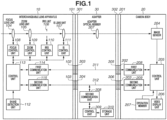
- the imaging system according to the first exemplary embodiment includes a first communication path for communication between a camera body (imaging apparatus) and an interchangeable lens apparatus, and a second communication path for communication between the camera body and an adapter (intermediate accessory apparatus).
- Fig. 1 illustrates an example configuration of the imaging system according to the first exemplary embodiment.
- an interchangeable lens apparatus 10 includes a movable optical member.
- a camera body 20 includes an image sensor.
- An adapter 30 intermediate accessory apparatus, e.g., extender is detachably attached between the interchangeable lens apparatus 10 and the camera body 20.
- the interchangeable lens apparatus 10, the adapter 30, and the camera body 20 are attachable to and detachable from each other via mounts 101, 301, 302, and 201.
- the mount 101 is formed on the interchangeable lens apparatus 10, the mounts 301 and 302 are formed on the adapter 30, and the mount 201 is formed on the camera body 20.
- the mounts 101, 301, 302, and 201 are provided with one or more contacts (terminals) 102, 303, 305, and 202, respectively, for performing communication based on a first communication method.
- the contacts 102, 303, 305, and 202 are configured to become conductive with each other when the interchangeable lens 10, the adapter 30, and the camera body 20 are attached (connected) to each other.
- the first communication method is used by the camera body 20 to control the movable optical member in the interchangeable lens apparatus 10.
- the camera body 20 acquires control information related to the combination of the interchangeable lens apparatus 10 and the adapter 30 and then acquires the video data by using the control information.
- the control unit 205 of the camera body 20 transmits a communication command for acquiring the identification information (first identification information) about the interchangeable lens apparatus 10 to the interchangeable lens apparatus 10, based on the first communication method.
- the control unit 205 acquires the identification information for the interchangeable lens apparatus 10 from the adapter 30.
- the control unit 205 recognizes that the adapter 30 is attached to the camera body 20 through broadcast communication based on the second communication method.
- control unit 205 transmits a communication command for transmitting the identification information for the interchangeable lens apparatus 10, to the adapter 30 based on the second communication method.
- control unit 309 of the adapter 30 acquires (recognizes) the identification information.
- the individual information as the imaging control information may be related to, for example, the F number and focus sensitivity (ratio of the moving amount of the image plane to the moving amount of the focus lens unit 104) in addition to the focal distance.
- the individual information may also be related to the moving amount of the focus lens unit 104 for correcting the defocus amount detected by an automatic focus (AF) sensor.
- the individual information as the correction control information may be, in addition to the information for correcting the periphery light quantity reduction, information for correcting the magnification chromatic aberration and distortion with respect to the video data acquired by the camera body 20.
- the camera body 20 performs the correction on the video data based on the command.
- the command may include the coefficient of the n-th order polynomial related to the image height for obtaining a value (multiplication value) for the correction.
- the video display unit 206 of the camera body 20 displays the imaging condition (e.g., the focal distance, subject distance, and F number) in the imaging system including the combination of the interchangeable lens apparatus 10 and the adapter 30.
- the imaging condition e.g., the focal distance, subject distance, and F number
- the movable optical member is driven based on the command.
- control unit 205 of the camera body 20 acquires the individual information corresponding to the combination of the interchangeable lens apparatus 10 and the adapter 30 to suitably perform control related to the interchangeable lens apparatus 10. Since the control unit 205 can acquire only individual information to be required immediately at the start of power supply, it is possible to shorten the time period before the camera becomes ready for imaging.
- control unit 205 of the camera body 20 notifies the adapter 30 of the identification information for the interchangeable lens apparatus 10.
- the control unit 205 generates a communication command for notifying the adapter 30 of the identification information for the interchangeable lens apparatus 10.
- the control unit 205 transmits the communication command to the adapter 30 via the second communication unit 209.
- the control unit 309 of the adapter 30 receives the communication command via the second communication unit 308 and then interprets the command. As a result, the control unit 309 can identify the interchangeable lens apparatus 10.
- the interchangeable lens apparatus 10 When another adapter including an optical system is attached between the interchangeable lens apparatus 10 and the adapter 30, the interchangeable lens apparatus 10 identifies the other adapter and transmits the identification information for the other adapter to the camera body 20.
- the other adapter is identified by the interchangeable lens apparatus 10 through communication (communication via contacts) between the interchangeable lens apparatus 10 and the other adapter.
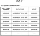
- the control information stored in the storage unit 310 will be described below with reference to Figs. 2 to 22 .
- the first column indicates the start address of data
- the second column indicates the name of the data
- the third column indicates the value.
- the start address is a unique number.
- the start address is represented by an 8-digit hexadecimal number (from 00000000h to FFFFFFFFh).
- Fig. 2 illustrates an example of storage information.
- the storage information is required by the control unit 309 of the adapter 30 to identify the accessory data corresponding to an accessory data identifier.
- the storage information includes the accessory data group configuration information and the accessory data group.
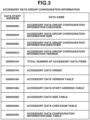
- Fig. 3 illustrates an example of the accessory data group configuration information.
- the accessory data group configuration information is used to identify specific accessory data from the accessory data group.
- the accessory data group configuration information includes an accessory data group configuration information checksum, an accessory data group configuration information size, an accessory data group configuration information identifier, and an accessory data group configuration information version.
- the accessory data group configuration information also includes the total number of accessory data items and the accessory data order.
- the accessory data group configuration information also includes an accessory data version table, an accessory data start address table, and an accessory data size table.
- the accessory data group configuration information also includes an accessory data checksum table and an accessory data configuration information size table.
- the accessory data group configuration information checksum is a value obtained as the sum of all of the data items included in the accessory data group configuration information other than the accessory data group configuration information checksum. Inspection (detection) for communication errors (data anomaly due to a communication error) can be performed by comparing the above-described value with the value obtained as the sum of all of the data items obtained in communication.
- the accessory data group configuration information size indicates the size of the accessory data group configuration information (number of bytes) and is used to read the accessory data group configuration information from the storage unit 310.
- the accessory data group configuration information version indicates the version of the accessory data group configuration information. A larger version number indicates a later version.
- the accessory data group configuration information version may be used to determine whether the control information needs to be updated.
- the total number of accessory data items indicates the total number of accessory data identifiers, and is used to identify one accessory data item together with the accessory data order (described below).
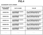
- Fig. 4 illustrates an example of the accessory data order.
- the accessory data order includes a plurality of accessory data identifiers.
- the accessory data order indicates the order of arrangements of a plurality of accessory data items equal in number to the total number of accessory data items.
- the accessory data identifier is information for identifying the accessory data, and may be the identification information (first identification information) for the interchangeable lens apparatus 10. For example, when the interchangeable lens apparatus 10 is an interchangeable lens apparatus A, the accessory data identifier is 01h. When the interchangeable lens apparatus 10 is an interchangeable lens apparatus B, the accessory data identifier is 02h.
- the accessory data identifier is not limited to a hexadecimal number but may be any number that uniquely identifies the accessory data.
- Fig. 5 illustrates an example of an accessory data version table.
- the accessory data version table includes a plurality of accessory data versions.
- the accessory data version is a number that indicates the version of specific accessory data arranged according to the accessory data order. A larger version number indicates a later version.
- the accessory data version may be used to determine whether the accessory data needs to be updated.
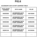
- Fig. 6 illustrates an example of an accessory data start address table.
- the accessory data start address table includes a plurality of accessory data start addresses.
- the accessory data start address indicates the start address of specific accessory data arranged according to the accessory data order.
- Fig. 7 illustrates an example of an accessory data size table.
- the accessory data size table includes a plurality of accessory data sizes.
- the accessory data size indicates the size of specific accessory data arranged according to the accessory data order.
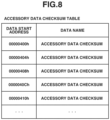
- Fig. 8 illustrates an example of an accessory data checksum table.
- the accessory data checksum table includes a plurality of accessory data checksums.
- the accessory data checksum is a value obtained as the sum of the accessory data items. Communication error inspection can be performed by comparing this value with the value obtained as the sum of the accessory data items obtained in communication.
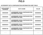
- Fig. 9 illustrates an example of an accessory data configuration information size table.
- the accessory data configuration information size table includes a plurality of accessory data configuration information sizes.
- the accessory data configuration information size indicates the size of the accessory data configuration information related to specific accessory data arranged according to the accessory data order.
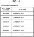
- Fig. 10 illustrates an example of an accessory data group.
- the accessory data group includes a plurality of accessory data items.
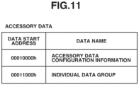
- Fig. 11 illustrates an example of accessory data.
- the accessory data corresponds to the combination of the adapter 30 and the interchangeable lens apparatus 10 and includes the accessory data configuration information and the individual data group.
- the accessory data configuration information checksum is a value obtained as the sum of all of the data items included in the accessory data configuration information other than the accessory data configuration information checksum. Communication error inspection can be performed by comparing this value with the value obtained as the sum of all of the data items obtained in communication.
- the total number of individual data items is used to identify one individual data item together with the individual data order (described below).
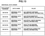
- Fig. 13 illustrates an example of the individual data order.
- the individual data order includes a plurality of individual data identifiers.
- the individual data order indicates the order of arrangement of the plurality of individual data items equal in number to the total number of individual data items.
- the individual data identifier is used to identify specific part of the control information corresponding to the combination of the adapter 30 and the interchangeable lens apparatus 10.
- the above-mentioned second configuration information is information indicating attributes of a plurality of pieces of partial information respectively associated with a plurality of pieces of second identification information, and is also referred to as accessory data configuration information. For example, when the partial information relates to a subject distance, the individual data identifier is 01h. When the partial information relates to focus sensitivity, the individual data identifier is 02h.
- the individual data identifier is not limited to a hexadecimal number but may be any number that uniquely identifies the individual data.
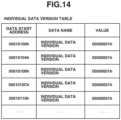
- Fig. 14 illustrates an example of the individual data version table.
- the individual data version table includes a plurality of individual data versions.
- the individual data version is a number indicating the version of specific individual data arranged according to the individual data order. a larger version number indicates a later version.
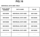
- Fig. 16 illustrates an example of the individual data size table.
- the individual data size table includes a plurality of individual data sizes.
- the individual data size indicates the size of specific individual data arranged according to the individual data order.
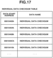
- Fig. 17 illustrates an example of the individual data checksum table.
- the individual data checksum table includes a plurality of individual data checksums.
- the individual data checksum is a value obtained as the sum of all of the data items included in the individual data. Communication error inspection can be performed by comparing this value with the value obtained as the sum of all of the data items obtained in communication.
- Fig. 18 illustrates an example of the individual data configuration information size table.
- the individual data configuration information size table includes a plurality of individual data configuration information sizes.
- the individual data configuration information size indicates the size of the individual data configuration information for specific individual data arranged according to the individual data order.
- Fig. 19 illustrates an example of the individual data group.
- the individual data group includes a plurality of individual data items.
- Fig. 20 illustrates an example of the individual data.
- the individual data corresponds to the combination of the adapter 30 and the interchangeable lens apparatus 10, and includes the individual data configuration information and the data table.
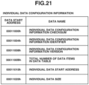
- Fig. 21 illustrates an example of the individual data configuration information.
- the individual data configuration information includes an individual data configuration information checksum, an individual data configuration information identifier, and an individual data configuration information version.
- the individual data configuration information also includes the total number of data items in the data table, an individual data start address, and an individual data size.
- the individual data configuration information checksum is a value obtained as the sum of all of the data items included in the individual data configuration information other than the individual data configuration information checksum. Communication error inspection can be performed by comparing this value with the value obtained as the sum of all of the data items obtained through communication.
- the individual data version is a number indicating the version of the individual data. A larger version number indicates a later version.
- the individual data table start address indicates the start address of the individual data table.
- the individual data table size indicates the size of the individual data table.
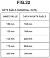
- Fig. 22 illustrates an example of the data table.
- This example indicates that data in the data table (partial information in the control information) relates to a focal distance.
- the data table serves as an index showing index values for focal distances.
- the index value is the focal distance of the interchangeable lens apparatus 10
- the individual data is the focal distance corresponding to the combination of the interchangeable lens apparatus 10 and the adapter 30.
- the adapter 30 is assumed to include a magnification optical system that magnifies the focal distance 1.5 times.
- Such a data table enables the control unit 205 of the camera body 20 to obtain the focal distance corresponding to the combination of the interchangeable lens apparatus 10 and the adapter 30 by using the focal distance of the interchangeable lens apparatus 10 as the INDEX value.
- the accessory data group configuration information is used.
- the accessory data group configuration information, the accessory data configuration information, and the individual data configuration information are used.
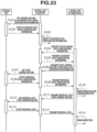
- FIG. 23 illustrates an example flow of the individual data acquisition processing.
- the control unit 309 of the adapter 30 is assumed to have already acquired the accessory data identifier from the camera body 20.
- step S102 the storage unit 310 outputs the accessory data group configuration information to the control unit 309 according to the set address and size.
- step S103 the control unit 309 identifies the accessory data start address corresponding to the accessory data identifier based on the accessory data identifier and the accessory data group configuration information. Likewise, the control unit 309 identifies the accessory data size, the accessory data checksum, and the accessory data configuration information size.
- step S104 the control unit 205 of the camera body 20 requests the adapter 30 to read data for the accessory data configuration information size from the (invariable and known) accessory data start address.
- step S105 the control unit 309 of the adapter 30 transmits the accessory data configuration information identified in step S103 to the camera body 20.
- step S106 the control unit 205 of the camera body 20 transmits the start address and size of the individual data configuration information to the adapter 30.
- step S107 the control unit 309 of the adapter 30 sets the start address and size in the storage unit 310.
- step S108 the storage unit 310 outputs the individual data configuration information to the control unit 309 according to the set start address and size.
- step S109 the control unit 309 of the adapter 30 transmits the individual data configuration information to the camera body 20.
- step S110 the control unit 205 of the camera body 20 performs communication error inspection on the communication data by using the received individual data configuration information and the individual data configuration information checksum included in the individual data configuration information. If a communication error is detected, the processing may be repeated from step S106.
- the control unit 205 identifies the individual data start address corresponding to the same individual data configuration information identifier as the first communication identifier included in the individual data configuration information.
- the control unit 205 also identifies the individual data size corresponding to the individual data configuration information identifier.
- the control unit 205 determines whether new individual data needs to be acquired, based on the individual data configuration information version.
- the control unit 205 makes an inquiry in advance to the interchangeable lens apparatus 10 about an available command through the first communication.
- the control unit 205 identifies the individual data having the same individual data configuration information identifier as the first communication identifier of the command.
- the camera body 20 may have a command list for each type of the interchangeable lens 10.
- step S111 the control unit 205 of the camera body 20 transmits the individual data start address and the individual data size identified in step S110, to the adapter 30.
- step S113 the storage unit 310 outputs the individual data start address and the individual data size to the control unit 309 of the adapter 30.
- step S114 the control unit 309 of the adapter 30 transmits the individual data to the camera body 20.
- step S115 the control unit 205 of the camera body 20 performs communication error inspection based on the individual data identification information checksum in the received individual data. If a communication error is detected, the processing may be repeated from step S111.
- the above-described processing enables the control unit 205 of the camera body 20 to acquire necessary individual data from the adapter 30.
- the control unit 205 thus can perform control related to the interchangeable lens apparatus 10 based on the status information acquired from the interchangeable lens apparatus 10.
- FIG. 24 illustrates an example flow of the accessory data acquisition processing. Processing in steps S101 to S105 in Fig. 24 is similar to the processing in Fig. 23 , and redundant descriptions thereof will be omitted.
- step S201 the control unit 205 of the camera body 20 transmits the accessory data start address and the accessory data size received in step S105, to the adapter 30.
- step S202 the control unit 309 of the adapter 30 sets the accessory data start address and the accessory data size in the storage unit 310.
- step S203 the storage unit 310 outputs the accessory data to the control unit 309 according to the set accessory data start address and accessory data size.
- step S204 the control unit 309 of the adapter 30 transmits the accessory data to the camera body 20.
- step S205 the camera body 20 performs communication error inspection based on the accessory data checksum in the accessory data received in step S105. If a communication error is detected, the processing may be repeated step S201.
- the control unit 305 of the camera body 20 can obtain the accessory data configuration information by taking out accessory data for the accessory data configuration information size from the top of the accessory data. This makes it possible to acquire necessary individual data by using the individual data start address and the individual data size included in the accessory data configuration information.
- the present exemplary embodiment enables providing an intermediate accessory apparatus that is advantageous for an imaging apparatus to control an interchangeable lens apparatus.
- the present exemplary embodiment also enables providing an imaging apparatus that is advantageous in controlling an interchangeable lens apparatus.
- the present exemplary embodiment also enables providing an imaging system that can produce the effects of the interchangeable lens apparatus and the imaging apparatus.
- FIG. 25 illustrates an example flow of the processing for updating the entire data.
- the control unit 205 is assumed to have already had new storage information via a storage medium.
- step S301 the control unit 205 of the camera body 20 transmits the new storage information (update information) to the adapter 30.
- step S302 the control unit 309 of the adapter 30 performs communication error inspection by using the received accessory data group configuration information checksum. If a communication error is detected, the processing may be repeated from step S301.
- step S303 the control unit 309 of the adapter 30 writes the received storage information in the storage unit 310 by using the received accessory data group configuration information data size as the write data size.
- the start address of the writing is assumed to be known.
- step S304 the storage unit 310 transmits the result of writing the storage information to the control unit 309.
- step S305 the control unit 309 checks whether the storage information stored in the storage unit 310 coincides with the transmitted storage information.
- step S306 the control unit 309 notifies the camera body 20 of the completion of the updating.
- the above-described processing enables updating the storage information in the storage unit 310 with the storage information from the camera body 20 (or an external apparatus).
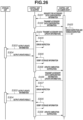
- FIG. 26 illustrates an example flow of the accessory data update processing. Processing in steps S303 to S306 is similar to the processing in Fig. 25 , and redundant descriptions thereof will be omitted.
- the control unit 309 of the adapter 30 is assumed to have already read the accessory data configuration information from the storage unit 310.
- step S401 the control unit 205 of the camera body 20 requests the adapter 30 for the accessory data configuration information.
- step S402 the control unit 309 of the adapter 30 transmits the accessory data configuration information to the camera body 20.
- step S404 the control unit 205 transmits the accessory data to be updated identified in step S403, to the adapter 30.
- step S405 the control unit 309 of the adapter 30 performs communication error inspection by using the accessory data checksum of the received accessory data. If a communication error is detected, the processing may be repeated from step S404. When there is a plurality of accessory data items to be updated, the processing in steps S404 to S405 and the processing in steps S303 to S306 are repeated.
- step S406 the control unit 205 transmits new accessory data configuration information as update information.
- the accessory data to be updated can be identified by checking the accessory data configuration information version. If the version is the latest version, the control unit 309 determines that there is no accessory data to be updated. On the other hand, if the version is not the latest version, the control unit 309 performs the following processing. More specifically, the control unit 309 determines whether each accessory data version is the latest version. As a result, the control unit 309 identifies the accessory data of which the version is not the latest version, as the data to be updated. The control unit 309 also identifies accessory data to be added, as the accessory data to be updated.
- the unit of data to be updated may be individual data instead of accessory data.
- the control unit 309 may perform this determination based on the individual data configuration information version.
- the storage information stored in the storage unit 310 having the above-described data structure enables the camera body 20 to efficiently update the storage information not only in whole but also in units of the accessory data and the individual data.
- the present exemplary embodiment enables providing an intermediate accessory apparatus that is advantageous for an imaging apparatus to control an interchangeable lens apparatus.
- the present exemplary embodiment also enables providing an imaging apparatus that is advantageous in controlling an interchangeable lens apparatus.
- the present exemplary embodiment also enables providing an imaging system that can produce the effects of the interchangeable lens apparatus and the imaging apparatus.
- Embodiment(s) of the present invention can also be realized by a computer of a system or apparatus that reads out and executes computer executable instructions (e.g., one or more programs) recorded on a storage medium (which may also be referred to more fully as a 'non-transitory computer-readable storage medium') to perform the functions of one or more of the above-described embodiment(s) and/or that includes one or more circuits (e.g., application specific integrated circuit (ASIC)) for performing the functions of one or more of the above-described embodiment(s), and by a method performed by the computer of the system or apparatus by, for example, reading out and executing the computer executable instructions from the storage medium to perform the functions of one or more of the above-described embodiment(s) and/or controlling the one or more circuits to perform the functions of one or more of the above-described embodiment(s).
- computer executable instructions e.g., one or more programs
- a storage medium which may also be referred to more fully as
- the computer may comprise one or more processors (e.g., central processing unit (CPU), micro processing unit (MPU)) and may include a network of separate computers or separate processors to read out and execute the computer executable instructions.
- the computer executable instructions may be provided to the computer, for example, from a network or the storage medium.
- the storage medium may include, for example, one or more of a hard disk, a random-access memory (RAM), a read only memory (ROM), a storage of distributed computing systems, an optical disk (such as a compact disc (CD), digital versatile disc (DVD), or Blu-ray Disc (BD) TM ), a flash memory device, a memory card, and the like.
Landscapes
- Physics & Mathematics (AREA)
- General Physics & Mathematics (AREA)
- Engineering & Computer Science (AREA)
- Multimedia (AREA)
- Signal Processing (AREA)
- Structure And Mechanism Of Cameras (AREA)
- Studio Devices (AREA)
- Accessories Of Cameras (AREA)
Applications Claiming Priority (1)
| Application Number | Priority Date | Filing Date | Title |
|---|---|---|---|
| JP2020155594A JP7286597B2 (ja) | 2020-09-16 | 2020-09-16 | 中間アクセサリ装置、撮像装置、撮像システム、撮像方法、およびプログラム |
Publications (2)
| Publication Number | Publication Date |
|---|---|
| EP3971641A1 EP3971641A1 (en) | 2022-03-23 |
| EP3971641B1 true EP3971641B1 (en) | 2025-05-21 |
Family
ID=77640632
Family Applications (1)
| Application Number | Title | Priority Date | Filing Date |
|---|---|---|---|
| EP21195144.7A Active EP3971641B1 (en) | 2020-09-16 | 2021-09-06 | Intermediate accessory apparatus, image pickup apparatus, image pickup system, and program |
Country Status (4)
| Country | Link |
|---|---|
| US (1) | US11841603B2 (enExample) |
| EP (1) | EP3971641B1 (enExample) |
| JP (1) | JP7286597B2 (enExample) |
| CN (1) | CN114268712A (enExample) |
Families Citing this family (3)
| Publication number | Priority date | Publication date | Assignee | Title |
|---|---|---|---|---|
| JP7208203B2 (ja) * | 2020-09-16 | 2023-01-18 | キヤノン株式会社 | 中間アクセサリ装置、撮像装置、撮像システム、処理方法、およびプログラム |
| JP7547132B2 (ja) * | 2020-09-16 | 2024-09-09 | キヤノン株式会社 | 撮像装置、アクセサリ装置および制御方法 |
| JP7566545B2 (ja) | 2020-09-16 | 2024-10-15 | キヤノン株式会社 | 撮像装置、アクセサリ装置および制御方法 |
Citations (1)
| Publication number | Priority date | Publication date | Assignee | Title |
|---|---|---|---|---|
| US20210168278A1 (en) * | 2019-11-29 | 2021-06-03 | Canon Kabushiki Kaisha | Image pickup apparatus, image pickup accessory, and intermediate accessory |
Family Cites Families (13)
| Publication number | Priority date | Publication date | Assignee | Title |
|---|---|---|---|---|
| JPH073546B2 (ja) * | 1985-10-08 | 1995-01-18 | キヤノン株式会社 | カメラ |
| JPH0782181B2 (ja) * | 1986-02-01 | 1995-09-06 | 株式会社ニコン | アクセサリー交換可能なカメラ |
| JPS63141030A (ja) * | 1986-12-04 | 1988-06-13 | Sigma:Kk | 中間アクセサリ−の補正情報を備えた交換レンズの情報出力装置 |
| JPS63199330A (ja) * | 1987-02-16 | 1988-08-17 | Nikon Corp | 中間鏡筒 |
| US5003336A (en) * | 1988-02-29 | 1991-03-26 | Minolta Camera Kabushiki Kaisha | Camera system |
| JPH05313062A (ja) * | 1992-05-07 | 1993-11-26 | Canon Inc | 制御装置 |
| US7725017B2 (en) * | 2005-11-09 | 2010-05-25 | Panasonic Corporation | Image pickup apparatus and image pickup system |
| JP5618582B2 (ja) * | 2010-03-17 | 2014-11-05 | キヤノン株式会社 | カメラ本体、調整用工具、交換レンズ、アクセサリ、カメラシステム、通信システム、及びアクセサリの制御方法 |
| CN105866917A (zh) * | 2011-05-31 | 2016-08-17 | 株式会社尼康 | 镜头镜筒及相机机身 |
| KR20150030557A (ko) * | 2013-09-12 | 2015-03-20 | 삼성전자주식회사 | 렌즈 교환식 시스템 카메라의 제어방법 및 제어장치 |
| JP7102217B2 (ja) * | 2017-05-31 | 2022-07-19 | キヤノン株式会社 | 撮像装置、交換レンズ、中間アクセサリ及びこれらの制御方法 |
| US10976644B2 (en) * | 2018-07-31 | 2021-04-13 | Canon Kabushiki Kaisha | Imaging apparatus, interchangeable lens, accessory apparatus, and control methods therefor |
| JP7208203B2 (ja) * | 2020-09-16 | 2023-01-18 | キヤノン株式会社 | 中間アクセサリ装置、撮像装置、撮像システム、処理方法、およびプログラム |
-
2020
- 2020-09-16 JP JP2020155594A patent/JP7286597B2/ja active Active
-
2021
- 2021-09-06 EP EP21195144.7A patent/EP3971641B1/en active Active
- 2021-09-09 US US17/470,651 patent/US11841603B2/en active Active
- 2021-09-16 CN CN202111083470.5A patent/CN114268712A/zh active Pending
Patent Citations (1)
| Publication number | Priority date | Publication date | Assignee | Title |
|---|---|---|---|---|
| US20210168278A1 (en) * | 2019-11-29 | 2021-06-03 | Canon Kabushiki Kaisha | Image pickup apparatus, image pickup accessory, and intermediate accessory |
Also Published As
| Publication number | Publication date |
|---|---|
| CN114268712A (zh) | 2022-04-01 |
| US20220082904A1 (en) | 2022-03-17 |
| EP3971641A1 (en) | 2022-03-23 |
| JP7286597B2 (ja) | 2023-06-05 |
| US11841603B2 (en) | 2023-12-12 |
| JP2022049401A (ja) | 2022-03-29 |
Similar Documents
| Publication | Publication Date | Title |
|---|---|---|
| EP3971641B1 (en) | Intermediate accessory apparatus, image pickup apparatus, image pickup system, and program | |
| US12055787B2 (en) | Imaging apparatus, interchangeable lens, intermediate accessory, and control methods therefor | |
| EP3697080B1 (en) | Electronic device and method for controlling auto focusing thereof | |
| CN102572241B (zh) | 成像系统、安装适配器、成像设备 | |
| US20210243372A1 (en) | Imaging apparatus and interchangeable lens apparatus | |
| US10976644B2 (en) | Imaging apparatus, interchangeable lens, accessory apparatus, and control methods therefor | |
| JP2005062459A (ja) | レンズ交換式カメラ及びカメラシステム | |
| US11706523B2 (en) | Imaging apparatus, accessory apparatus, and communication control method | |
| US20100103284A1 (en) | Image sensing apparatus, registration apparatus, and control method and program therefor | |
| CN102971669B (zh) | 相机机身以及更换镜头 | |
| US10277799B2 (en) | Image capturing apparatus, and control method and storage medium thereof | |
| US10845613B2 (en) | Image pickup apparatus executing function based on shake, control method for same, and storage medium storing control program therefor | |
| US20170180638A1 (en) | Lens apparatus and image capturing apparatus | |
| US11930271B2 (en) | Intermediate accessory apparatus, image pickup apparatus, image pickup system, processing method, and storage medium | |
| CN117097980A (zh) | 相机及其图像采集方法、装置和接入不同镜头的转接环 | |
| US10841479B2 (en) | Operation apparatus, system, and image pickup apparatus | |
| US11812143B2 (en) | Imaging apparatus, accessory apparatus, and methods for controlling same | |
| CN111095333A (zh) | 信息终端、信息处理方法、信息处理程序及信息处理系统 | |
| JP2024076794A5 (enExample) | ||
| JP2016015056A (ja) | 光学機器 |
Legal Events
| Date | Code | Title | Description |
|---|---|---|---|
| PUAI | Public reference made under article 153(3) epc to a published international application that has entered the european phase |
Free format text: ORIGINAL CODE: 0009012 |
|
| STAA | Information on the status of an ep patent application or granted ep patent |
Free format text: STATUS: THE APPLICATION HAS BEEN PUBLISHED |
|
| AK | Designated contracting states |
Kind code of ref document: A1 Designated state(s): AL AT BE BG CH CY CZ DE DK EE ES FI FR GB GR HR HU IE IS IT LI LT LU LV MC MK MT NL NO PL PT RO RS SE SI SK SM TR |
|
| STAA | Information on the status of an ep patent application or granted ep patent |
Free format text: STATUS: REQUEST FOR EXAMINATION WAS MADE |
|
| 17P | Request for examination filed |
Effective date: 20220330 |
|
| RBV | Designated contracting states (corrected) |
Designated state(s): AL AT BE BG CH CY CZ DE DK EE ES FI FR GB GR HR HU IE IS IT LI LT LU LV MC MK MT NL NO PL PT RO RS SE SI SK SM TR |
|
| STAA | Information on the status of an ep patent application or granted ep patent |
Free format text: STATUS: EXAMINATION IS IN PROGRESS |
|
| 17Q | First examination report despatched |
Effective date: 20230726 |
|
| GRAP | Despatch of communication of intention to grant a patent |
Free format text: ORIGINAL CODE: EPIDOSNIGR1 |
|
| STAA | Information on the status of an ep patent application or granted ep patent |
Free format text: STATUS: GRANT OF PATENT IS INTENDED |
|
| INTG | Intention to grant announced |
Effective date: 20241216 |
|
| GRAS | Grant fee paid |
Free format text: ORIGINAL CODE: EPIDOSNIGR3 |
|
| GRAA | (expected) grant |
Free format text: ORIGINAL CODE: 0009210 |
|
| STAA | Information on the status of an ep patent application or granted ep patent |
Free format text: STATUS: THE PATENT HAS BEEN GRANTED |
|
| AK | Designated contracting states |
Kind code of ref document: B1 Designated state(s): AL AT BE BG CH CY CZ DE DK EE ES FI FR GB GR HR HU IE IS IT LI LT LU LV MC MK MT NL NO PL PT RO RS SE SI SK SM TR |
|
| REG | Reference to a national code |
Ref country code: GB Ref legal event code: FG4D |
|
| REG | Reference to a national code |
Ref country code: CH Ref legal event code: EP |
|
| REG | Reference to a national code |
Ref country code: DE Ref legal event code: R096 Ref document number: 602021031042 Country of ref document: DE |
|
| REG | Reference to a national code |
Ref country code: IE Ref legal event code: FG4D |
|
| REG | Reference to a national code |
Ref country code: NL Ref legal event code: MP Effective date: 20250521 |
|
| PG25 | Lapsed in a contracting state [announced via postgrant information from national office to epo] |
Ref country code: PT Free format text: LAPSE BECAUSE OF FAILURE TO SUBMIT A TRANSLATION OF THE DESCRIPTION OR TO PAY THE FEE WITHIN THE PRESCRIBED TIME-LIMIT Effective date: 20250922 Ref country code: FI Free format text: LAPSE BECAUSE OF FAILURE TO SUBMIT A TRANSLATION OF THE DESCRIPTION OR TO PAY THE FEE WITHIN THE PRESCRIBED TIME-LIMIT Effective date: 20250521 Ref country code: ES Free format text: LAPSE BECAUSE OF FAILURE TO SUBMIT A TRANSLATION OF THE DESCRIPTION OR TO PAY THE FEE WITHIN THE PRESCRIBED TIME-LIMIT Effective date: 20250521 |
|
| REG | Reference to a national code |
Ref country code: LT Ref legal event code: MG9D |
|
| PG25 | Lapsed in a contracting state [announced via postgrant information from national office to epo] |
Ref country code: NO Free format text: LAPSE BECAUSE OF FAILURE TO SUBMIT A TRANSLATION OF THE DESCRIPTION OR TO PAY THE FEE WITHIN THE PRESCRIBED TIME-LIMIT Effective date: 20250821 Ref country code: GR Free format text: LAPSE BECAUSE OF FAILURE TO SUBMIT A TRANSLATION OF THE DESCRIPTION OR TO PAY THE FEE WITHIN THE PRESCRIBED TIME-LIMIT Effective date: 20250822 |
|
| PG25 | Lapsed in a contracting state [announced via postgrant information from national office to epo] |
Ref country code: NL Free format text: LAPSE BECAUSE OF FAILURE TO SUBMIT A TRANSLATION OF THE DESCRIPTION OR TO PAY THE FEE WITHIN THE PRESCRIBED TIME-LIMIT Effective date: 20250521 Ref country code: PL Free format text: LAPSE BECAUSE OF FAILURE TO SUBMIT A TRANSLATION OF THE DESCRIPTION OR TO PAY THE FEE WITHIN THE PRESCRIBED TIME-LIMIT Effective date: 20250521 |
|
| PG25 | Lapsed in a contracting state [announced via postgrant information from national office to epo] |
Ref country code: BG Free format text: LAPSE BECAUSE OF FAILURE TO SUBMIT A TRANSLATION OF THE DESCRIPTION OR TO PAY THE FEE WITHIN THE PRESCRIBED TIME-LIMIT Effective date: 20250521 |
|
| PGFP | Annual fee paid to national office [announced via postgrant information from national office to epo] |
Ref country code: GB Payment date: 20250820 Year of fee payment: 5 |
|
| PG25 | Lapsed in a contracting state [announced via postgrant information from national office to epo] |
Ref country code: HR Free format text: LAPSE BECAUSE OF FAILURE TO SUBMIT A TRANSLATION OF THE DESCRIPTION OR TO PAY THE FEE WITHIN THE PRESCRIBED TIME-LIMIT Effective date: 20250521 |
|
| PG25 | Lapsed in a contracting state [announced via postgrant information from national office to epo] |
Ref country code: RS Free format text: LAPSE BECAUSE OF FAILURE TO SUBMIT A TRANSLATION OF THE DESCRIPTION OR TO PAY THE FEE WITHIN THE PRESCRIBED TIME-LIMIT Effective date: 20250821 |
|
| PG25 | Lapsed in a contracting state [announced via postgrant information from national office to epo] |
Ref country code: IS Free format text: LAPSE BECAUSE OF FAILURE TO SUBMIT A TRANSLATION OF THE DESCRIPTION OR TO PAY THE FEE WITHIN THE PRESCRIBED TIME-LIMIT Effective date: 20250921 |
|
| PG25 | Lapsed in a contracting state [announced via postgrant information from national office to epo] |
Ref country code: LV Free format text: LAPSE BECAUSE OF FAILURE TO SUBMIT A TRANSLATION OF THE DESCRIPTION OR TO PAY THE FEE WITHIN THE PRESCRIBED TIME-LIMIT Effective date: 20250521 |